

Page 1

Airlines & Cvionics Products
Honeywell International, Inc.
15001 N.E. 36 th Street
Redmond, WA 98052
Enhanced Ground Proximity
Warning System
MK XXII
for
Rotorwing
Aircraft
Installation Manual
060-4314-225 Rev C
Part Numbers:
965-1590-006
965-1590-008
965-1590-010
965-1590-011
Release Date: 12/14/00
CAGE CODE: 97896 SCALE: NONE SIZE: A DWG NO: 060-4314-225 REV:C SHEET 1 OF 254
Page 2

Honeywell
MK XXII EGPWS Installation Manual
This document is an unpublished work. Copyright 2000 Honeywell, International, Inc. All
rights reserved.
This document a nd all informati on and expressio n contained herein are the property of Honeywell International
Inc., and is provided to the recipient i n confidence on a “nee d to know” basis. Your use of this document is strictly
limited to a legit imate business purpose requiring the information c ontained therein. Your use of this document
constitutes acceptance of these terms.
CAGE CODE: 97896 SCALE: NONE SIZE: A DWG NO: 060-4314-225 REV: C
SHEET
2
Page 3

Honeywell
MK XXII EGPWS Installation Manual
Typed names constitute approval signatures. Actual signatures are on file at Honeywell in
Redmond, WA.
DRAWN
CHECK
ENGR
Dennis Martin 12/8/00
Sara Stark 12/8/00
Dennis Martin 12/8/00
MFG
QA
APVD
Dennis Martin 12/8/00
APVD
REVISIONS
SH REV DESCRIPTION DATE APPROVED
ALL A Added Software –008 Revisions.
8/9/01
8/9/01
S. Wright
D. Martin
Reason: 01 Severity: 10
ALL B Added Software –010 Revisions.
Reason: 01 Severity: 10
ALL C Added Software –011 Revisions.
Reason: 01 Severity: 10
3/22/02
3/22/02
6/07/02
6/7/02
D. Martin
R Gilliland
D Martin
T Curtis
CAGE CODE: 97896 SCALE: NONE SIZE: A DWG NO: 060-4314-225 REV: C
SHEET
3
Page 4

Honeywell
MK XXII EGPWS Installation Manual
CAGE CODE: 97896 SCALE: NONE SIZE: A DWG NO: 060-4314-225 REV: C
SHEET
4
Page 5

Honeywell
MK VI MK VIII EGPWS Installation Design Guide
TABLE OF CONTENTS
SECTION I – GENERAL INFORMATION............................................................................................16
1.1 I
NTRODUCTION.................................................................................................................................... 16
1.2 A
PPLICABILITY.................................................................................................................................... 16
1.3 H
OW TO USE THIS DOCUMENT ........................................................................................................... 16
1.4 R
EFERENCE DOCUMENTS .................................................................................................................... 17
1.5 D
ESCRIPTION OF EQUIPMENT...............................................................................................................18
1.5.1 MK XXII EGPWS Computer........................................................................................................ 19
1.5.2 MK XXII EGPWS Configuration Module.................................................................................... 19
1.5.3 GPS Antenna................................................................................................................................ 19
1.5.4 OAT Sensor..................................................................................................................................19
1.5.5 Smart Cable (PCMCIA Interface)................................................................................................20
1.6 T
ECHNICAL CHARACTERISTICS ........................................................................................................... 21
1.7 U
NITS SUPPLIED ..................................................................................................................................22
1.7.1 MK XXII EGPWS......................................................................................................................... 22
note 1: -0XX defines the Application software version......................................................................... 22
1.7.2 Configuration Module..................................................................................................................22
1.7.3 Smart Cable (PCMCIA Interface)................................................................................................22
1.8 I
NSTALLATION AND ACCESSORIES KITS .............................................................................................. 24
1.8.1 MK XXII EGPWS Installation Kits.............................................................................................. 24
1.8.2 RS-232 Cable............................................................................................................................... 24
1.8.3 Smart Cable................................................................................................................................. 24
1.8.4 Terrain Database Cards.............................................................................................................. 25
1.8.5 Flight History Card ..................................................................................................................... 25
1.9 A
CCESSORIES REQUIRED BUT NOT SUPPLIED.......................................................................................25
1.9.1 ARINC 453 Terrain Display wiring.............................................................................................25
1.9.2 GPS Antenna & cable.................................................................................................................. 26
1.9.3 Circuit Breaker............................................................................................................................ 26
1.9.4 Annunciators & Switch/Annunciators.......................................................................................... 26
1.9.4.1 GPWS Warning (red) P/TEST; switch/annunciator assembly............................................................... 26
1.9.4.2 GPWS Caution (amber) G/S CANCLD switch/annunciator assembly.................................................. 27
1.9.4.3 LOW ALT / ON switch/annunciator assembly...................................................................................... 27
1.9.4.4 TERR INHIB / ON switch/annunciator assembly................................................................................. 27
1.9.4.5 AUDIO INHIBIT / ON switch/annunciator assembly........................................................................... 27
1.9.4.6 GPWS INOP / TERR INOP annunciator assemblies............................................................................. 27
1.9.4.7 TERR DISPLAY / ON switch/annunciator assemblies.........................................................................27
1.10 COCKPIT SPEAKER (OPTIONAL)......................................................................................................... 27
1.11 T
OOLS REQUIRED.............................................................................................................................. 28
1.11.1 Crimping Tool - P1, P2, P3...................................................................................................... 28
1.11.2 Contact Positioner - P1, P2, P3................................................................................................28
Proprietary notice on title page applies
CAGE CODE: 97896 SCALE: NONE SIZE: A DWG NO: 060-4314-225 REV: C SHEET 5
Page 6

Honeywell
MK VI MK VIII EGPWS Installation Design Guide
1.11.3 Insertion/Removal Tool - P1, P2, P3........................................................................................ 28
1.11.4 Spare Contacts - P1, P2, P3...................................................................................................... 28
1.12 L
ICENSE REQUIREMENTS................................................................................................................... 28
SECTION II - INSTALLATION ..............................................................................................................................33
2.1 I
NTRODUCTION.................................................................................................................................................... 33
2.2 U
NPACKING AND INSPECTING THE EQUIPMENT................................................................................................... 33
2.3 E
QUIPMENT INSTALLATION ................................................................................................................................. 33
2.3.1 General........................................................................................................................................................33
2.3.2 MK XXII Computer Location....................................................................................................................... 34
2.3.3 MK XXII Computer Installation...................................................................................................................34
2.3.4 Configuration Module Location .................................................................................................................. 35
2.3.5 Configuration Module Installation.............................................................................................................. 35
2.3.6 GPS Antenna location.................................................................................................................................. 44
2.3.7 GPS Antenna Installation............................................................................................................................ 44
2.3.8 OAT Sensor Location................................................................................................................................... 44
2.3.9 OAT Sensor Installation...............................................................................................................................44
2.3.10 Cockpit Annunciators / Switches................................................................................................................44
2.3.10.1 Description............................................................................................................................................................45
2.3.10.2 Location................................................................................................................................................................. 46
2.3.10.3 Inhibit Switch Functions and Selection .................................................................................................................48
2.3.10.3.1 Terrain Inhibit ................................................................................................................................................ 48
2.3.10.3.2 Audio Inhibit (Timed)....................................................................................................................................48
2.3.10.3.3 Audio Inhibit (Not Described Above)............................................................................................................ 48
2.3.10.3.4 Low Altitude Mode........................................................................................................................................48
SECTION III – SYSTEM PLANNING.................................................................................................................................57
3.1 I
NTRODUCTION.................................................................................................................................... 57
3.2 S
YSTEM WIRING/ ELECTRICAL INTERFACES........................................................................................57
3.2.1 Primary Power Input................................................................................................................................................57
3.2.2 Chassis Ground ........................................................................................................................................................57
3.2.3 GPS Antenna............................................................................................................................................................. 58
3.2.4 Analog and Digital Inputs.........................................................................................................................................58
3.2.5 Discrete Inputs..........................................................................................................................................................58
3.2.6 Serial Outputs...........................................................................................................................................................58
3.2.7 Audio Output.............................................................................................................................................................59
3.2.8 Discrete Outputs.......................................................................................................................................................59
3.2.9 Configuration Module...............................................................................................................................................59
3.3 C
ONFIGURABLE INTERFACES............................................................................................................... 60
3.3.1 Category 1 - Aircraft / Mode Type Select.................................................................................................................60
3.3.1.1 Aircraft / Mode Type............................................................................................................................. 60
3.3.1.2 Instructions............................................................................................................................................ 60
3.3.1.3 Generic Helicopter with and without Torque......................................................................................... 60
Proprietary notice on title page applies
CAGE CODE: 97896 SCALE: NONE SIZE: A DWG NO: 060-4314-225 REV: C SHEET 6
Page 7

Honeywell
MK VI MK VIII EGPWS Installation Design Guide
3.3.2 Category 2 – Air Data Input Select........................................................................................................................... 61
3.3.2.1 Instructions........................................................................................................... ................................. 61
3.3.2.2 Examples............................................................................................................... ................................ 62
3.3.2.3 Analog altitude and 500 ohm OAT........................................................................................ ........... 62
3.3.2.4 Digital – ARINC 429 (Cat. 2 ID 5, 1, 6)........................................................................................... 63
3.3.2.5 Digital –ARINC 575 (Cat. 2 ID 2).................................................................................................... 64
3.3.2.6 Shadin 2000 (Cat. 2 ID 10) ............................................................................................................... 65
3.3.2.7 Digital – ARINC 429 Dual IOC Buses (Cat. 2. ID 255)................................................................... 66
3.3.3 Category 3 – Position Input Select...........................................................................................................................67
3.3.3.1 Instructions............................................................................................................................................ 67
3.3.3.2 ARINC 743 Format ............................................................................................................................... 67
3.3.3.Examples.................................................................................................................................................. 68
3.3.3.1 ARINC 429 BUS (Cat. 3 ID 0,1,4,5)................................................................................................. 68
3.3.3.2 RS-232 Transmit-Receive, 9600 baud (Cat. 3 ID 3) ......................................................................... 68
3.3.3.3 Dual ARINC 429 BUS (Cat. 3 ID 255)............................................................................................. 69
3.3.4 Category 4 – Altitude Callouts .................................................................................................................................70
3.3.4.1 Instructions............................................................................................................................................ 70
3.3.5 Category 5 – Audio Menu Select .............................................................................................................................. 71
3.3.5.1 Instructions............................................................................................................................................ 71
3.3.6 Category 6 – Terrain Display Select ........................................................................................................................72
3.3.6.1 Instructions............................................................................................................................................ 72
3.3.6.2 TAD Selection....................................................................................................................................... 72
3.3.6.3 Terrain Display Configuration Group.................................................................................................... 73
3.3.6.4 Display Input Control Group............................................................................................ ..................... 75
3.3.6.5 Output 429 Bus Group........................................................................................................................... 75
3.3.6.6 Example................................................................................................................................................. 75
3.3.7 Category 7 – Options Select Group #1.....................................................................................................................81
3.3.7.1 Instructions............................................................................................................................................ 81
3.3.7.2 Steep Approach (Not Available in the Mk XXII).................................................................................. 81
3.3.7.3 TA&D Alternate Pop-up........................................................................................................................ 81
3.3.7.4 Peaks Mode ........................................................................................................................................... 82
3.3.7.5 Obstacle Awareness............................................................................................................................... 82
3.3.7.6 Bank Angle Callout Enabling................................................................................................................ 82
3.3.7.8 WOW Reversal...................................................................................................................................... 83
3.3.7.9 GPS Altitude Reference......................................................................................................................... 83
3.3.8 Category 8 – Radio Altitude Input Select..................................................................................................................84
3.3.8.1 Instructions............................................................................................................................................ 84
3.3.8.2 Example................................................................................................................................................. 84
3.3.8.3 Digital Radio Altitude Interface........................................................................................................ 84
3.3.8.4 Analog Radio Altitude Interface........................................................................................................ 85
3.3.9 Category 9 – Navigation Inputs Select..................................................................................................................... 86
3.3.9.1 Instructions............................................................................................................................................ 86
3.3.9.2 Example................................................................................................................................................. 87
Proprietary notice on title page applies
CAGE CODE: 97896 SCALE: NONE SIZE: A DWG NO: 060-4314-225 REV: C SHEET 7
Page 8

Honeywell
MK VI MK VIII EGPWS Installation Design Guide
3.3.9.3 Analog Glideslope Interface (cat. 9 ID 0,1,5) ................................................................................... 87
3.3.9.4 Digital Glideslope/Localizer Interface.............................................................................................. 88
3.3.9.5 Dual Glideslope Receiver.................................................................................................................. 88
3.3.10 Category 10 – Attitude Input Select........................................................................................................................89
3.3.10.1 Attitude Signals ................................................................................................................................... 89
3.3.10.2 Instructions.......................................................................................................... ................................ 89
3.3.10.3 Example............................................................................................................... ................................ 90
3.3.10.4 Analog Roll Angle (Synchro).......................................................................................................... 90
3.3.10.5 Digital ARINC 429 High Speed.......................................................................................... ............ 91
3.3.11 Category 11 – Heading Input Select.......................................................................................................................92
3.3.11.1 Instructions.......................................................................................................................................... 92
3.3.11.2 Magnetic Heading................................................................................................................................ 92
3.3.11.3 Example............................................................................................................................................... 93
3.3.11.3.1 Analog Heading (Synchro) (CAT. 11 ID 0)................................................................................. 93
3.3.11.3.2 Digital ARINC 429 High Speed........................................................................................ ........... 94
3.3.12 Category 12 – Windshear Input Select ...................................................................................................................95
3.3.12.1 Instruction............................................................................................................................................ 95
3.3.13 Category 13 – Input / Output Discrete Type Select................................................................................................96
3.3.13.1 Instruction............................................................................................................................................ 96
3.3.13.2 Input/Output Discretes......................................................................................................................... 96
3.3.13.3 Audio Inhibit Discrete..................................................................................................................... 97
3.3.13.4 Landing Gear Discrete..................................................................................................................... 97
3.3.13.5 Weight ON Wheels (WOW) Discrete............................................................................................. 97
3.3.13.6 Glideslope Cancel Discrete............................................................................................................. 98
3.3.13.7 Mode 6 Low Volume Discrete........................................................................................................ 98
3.3.13.8 Autopilot Engaged Discrete ............................................................................................................ 98
3.3.13.9 Terrain Awareness Inhibit............................................................................................................... 99
3.3.13.10 Self Test Discrete .......................................................................................................................... 99
3.3.13.11 Glideslope Inhibit Discrete............................................................................................................ 99
3.3.13.12 Timed Audio Inhibit Discrete...................................................................................................... 100
3.3.13.13 Low Altitude Mode Select Discrete............................................................................................ 100
3.3.13.14 Output Discretes.......................................................................................................................... 100
3.3.13.15 Lamp Format.......................................................................................................... ..................... 100
3.3.13.16 GPWS INOP Discrete................................................................................................................. 101
3.3.13.17 TAD INOP Discrete .................................................................................................................... 101
3.3.13.18 GPWS Warning Discrete............................................................................................................. 101
3.3.13.19 GPWS Alert Discrete .................................................................................................................. 101
3.3.13.20 Glideslope Cancel Discrete......................................................................................................... 101
3.3.13.21 TCAS Inhibit Discrete................................................................................................................. 101
3.3.13.22 Terrain Display Select #1 & #2 Discrete..................................................................................... 102
3.3.13.23 Timed Audio Inhibit Discrete...................................................................................................... 102
3.3.13.24 Low Altitude Mode Discrete....................................................................................................... 102
3.3.14 Category 14 – Audio Output Level.......................................................................................................................104
Proprietary notice on title page applies
CAGE CODE: 97896 SCALE: NONE SIZE: A DWG NO: 060-4314-225 REV: C SHEET 8
Page 9

Honeywell
MK VI MK VIII EGPWS Installation Design Guide
3.3.14.1 Instructions.......................................................................................................... .............................. 104
3.3.15 Category 15, Autorotation Threshold...................................................................................................................105
3.3.15.1 Instruction.......................................................................................................................................... 105
SECTION IV – CONFIGURATION MODULE PROGRAMMING AND REGIONAL TERRAIN
DATABASE LOADING........................................................................................................................................................109
4.1 I
NTRODUCTION.................................................................................................................................. 109
4.2 H
ARNESS CHECKOUT AND POWER CHECK ........................................................................................ 109
4.3 U
NIT INSTALLATION.......................................................................................................................... 109
4.4 EGPWC I
NITIALIZATION AND CONFIGURATION ............................................................................... 109
4.4.1 RS-232 Communication with the MK XXII EGPWS..................................................................109
4.4.2 EGPWC Front Panel Test Connector........................................................................................ 110
4.4.3 WinVIEWS................................................................................................................................. 110
4.4.4 WinVIEWS Operation................................................................................................................ 111
4.5 C
ONFIGURATION MODULE PROGRAMMING .......................................................................................111
4.5.1 CUW and CMR Commands..................................................................................................... .. 113
4.5.2 Configuration Module Reprogramming.....................................................................................114
4.6 R
EGIONAL TERRAIN DATABASE LOADING ........................................................................................ 115
4.6.1 Effectivity...................................................................................................................................115
4.6.2 Description ................................................................................................................................ 115
4.6.3 Approval .................................................................................................................................... 115
4.6.4 Material – Cost and Availability................................................................................................116
4.6.5 Accomplishment Instructions..................................................................................................... 117
4.6.6 Verification of the Terrain Database Version............................................................................ 118
SECTION V – CERTIFICATION 124
5.1 I
NTRODUCTION .................................................................................................................................124
5.2 C
ERTIFICATION PROCEDURE .............................................................................................................124
5.2.2 Equipment Location ...............................................................................................................................................124
5.2.3 FAA Requirements .................................................................................................................................................124
5.2.4 Ground Test ...........................................................................................................................................................124
5.2.5 Flight Manual Revision .........................................................................................................................................124
5.2.6 Flight Test ..............................................................................................................................................................125
5.2.7 Pilots Guide ...........................................................................................................................................................125
5.2.8 Failure Modes, Effects, and Safety Analysis ..........................................................................................................125
5.2.9 Existing STC’s .......................................................................................................................................................125
APPENDIX A.........................................................................................................................................................................127
CUSTOMER WORKSHEET...............................................................................................................................................127
APPENDIX B.........................................................................................................................................................................139
SAMPLE WIRING DIAGRAMS.........................................................................................................................................139
Proprietary notice on title page applies
CAGE CODE: 97896 SCALE: NONE SIZE: A DWG NO: 060-4314-225 REV: C SHEET 9
Page 10

Honeywell
MK VI MK VIII EGPWS Installation Design Guide
APPENDIX C.........................................................................................................................................................................143
WINVIEWS OPERATION INSTRUCTIONS...................................................................................................................143
APPENDIX D............................................................................................................................................149
VENDOR DRAWINGS............................................................................................................................ 149
D 1-0 V
ENDOR CONTACT INFORMATION.................................................................................................151
D1-1 EDMO................................................................................................................................. 153
D1-2 EMTEQ...............................................................................................................................154
GPS - RF Cable Sets......................................................................................................................... 154
TABLE 2 ............................................................................................................................................. 156
Table 2.A.1 Connectors (for TFLX cable series) - GPS ...................................................................156
TABLE 2 (continued).......................................................................................................................... 157
Table 2.B.1 Connectors (for PFLX cable series) – GPS.................................................................... 157
TOOL FRAME AND DIE PART NUMBERS....................................................................................... 158
I
NSTALLATION CONSIDERATIONS:........................................................................................................... 159
D1-3 Aerospace Optics................................................................................................................160
AEROSPACE OPTICS INC....................................................................................................................160
LED LIGHTING ...................................................................................................................................... 160
INTRODUCTION.................................................................................................................................................................166
E 1 P
E 2 P
E 3 S
ART NUMBER..........................................................................................................................................................166
URPOSE...................................................................................................................................................................166
YSTEM OVERVIEW..................................................................................................................................................166
E 4 ELECTRICAL INTERFACE....................................................................................................... ...........................167
E 4.1 Introduction.....................................................................................................................................................167
E 4.2 Signal Interfaces..............................................................................................................................................167
E 4.2.1 Grounds...........................................................................................................................................................167
E 4.2.2 Primary Power Input.......................................................................................................................................167
E 4.2.3 DC Analog Inputs............................................................................................................................................168
E 4.2.7 AC Analog Inputs.............................................................................................................................................170
E 4.2.9 ARINC 429/575 Digital Serial Bus Inputs................................................................................. ......................172
E 4.2.9.1 RS-232 / RS-422 Digital Serial Bus Inputs ..................................................................................................173
E 4.2.10 Discrete Inputs.............................................................................................................................................174
E 4.2.11 Configuration Module Interface..................................................................................................................175
E 4.2.12 GPS Antenna Input ......................................................................................................................................175
E 4.2.13 OAT Voltage Reference Output....................................................................................................................176
E 4.2.14 Lamp Driver Outputs...................................................................................................................................176
E 4.2.16 Audio Outputs..............................................................................................................................................176
E 4.2.17 ARINC Digital Serial Output Busses...........................................................................................................177
Proprietary notice on title page applies
CAGE CODE: 97896 SCALE: NONE SIZE: A DWG NO: 060-4314-225 REV: C SHEET 10
Page 11

Honeywell
MK VI MK VIII EGPWS Installation Design Guide
E 4.2.17.1 ARINC 429 Output Bus............................................................................................................................177
E 4.2.17.2 ARINC 453 Output Bus............................................................................................................................178
E 4.2.18 F
E 4.2.18.1 RS-232 M
RONT PANEL TEST INTERFACE........................................................................................................................178
AINTENANCE PORT (SERIAL PORT 4).............................................................................................178
E 4.2.18.2 PCMCIA / SmartCable Port ....................................................................................................................179
E 4.2.18.3 GSE Present Discrete Input.....................................................................................................................179
E 4.2.19 F
RONT PANEL STATUS INDICATORS .................................................................................................................179
E 5 AIRCRAFT APPLICATION DATA.......................................................................................................................180
E 5.1 C
E 5.2 C
ONFIGURATION TYPES........................................................................................................................................180
ONFIGURATION SELECTION................................................................................................................................180
E 5.3 Configuration Selection Tables........................................................................................................................ 182
E 5.3.1 Category 1, Aircraft / Mode Type Select..........................................................................................................183
E 5.3.2 Category 2, Air Data Input Select....................................................................................................................189
E 5.3.3 Category 3, Position Input Select...................................................................................................................195
E 5.3.4 Category 4, Altitude Callouts ..........................................................................................................................199
E 5.3.5 Category 5, Audio Menu Select........................................................................................................................201
E 5.3.6 Category 6, Terrain Display Select..................................................................................................................202
E 5.3.7 Category 7, Options 1 Select...........................................................................................................................231
E 5.3.8 Category 8, Radio Altitude Input Select...........................................................................................................233
E 5.3.9 Category 9, Navigation Input Select................................................................................................................236
E 5.3.10 Category 10, Attitude Input Select...............................................................................................................238
E 5.3.11 Category 11, Heading Input Select..............................................................................................................240
E 5.3.12 Category 12, Windshear Input Select...........................................................................................................241
E 5.3.13 Category 13, Input / Output Discrete Type Select .......................................................................................242
E 5.3.14 Category 14, Audio Output Level ................................................................................................................245
E 5.3.15 Category 15, Autorotation Threshold..........................................................................................................246
E 6 CONNECTOR INTERFACE...................................................................................................................................247
E 6.1 P
INOUT FOR FRONT CONNECTORS SORTED BY PIN NUMBER ................................................................................. 247
E 7 DEFINIT IONS ........................................................................................................................................................252
Proprietary notice on title page applies
CAGE CODE: 97896 SCALE: NONE SIZE: A DWG NO: 060-4314-225 REV: C SHEET 11
Page 12

Honeywell
MK XXII EGPWS Installation Manual
SECTION I
GENERAL INFORMATION
CAGE CODE: 97896 SCALE: NONE SIZE: A DWG NO: 060-4314-225 REV: C
SHEET
12
Page 13

Honeywell
MK XXII EGPWS Installation Manual
CAGE CODE: 97896 SCALE: NONE SIZE: A DWG NO: 060-4314-225 REV: C
SHEET
13
Page 14

Honeywell
MK XXII EGPWS Installation Manual
SECTION I – GENERAL INFORMATION
SECTION I – GENERAL INFORMATION............................................................................................16
1.1 I
NTRODUCTION.................................................................................................................................... 16
1.2 A
PPLICABILITY.................................................................................................................................... 16
1.3 H
OW TO USE THIS DOCUMENT ........................................................................................................... 16
1.4 R
EFERENCE DOCUMENTS .................................................................................................................... 17
1.5 D
ESCRIPTION OF EQUIPMENT...............................................................................................................18
1.5.1 MK XXII EGPWS Computer........................................................................................................ 19
1.5.2 MK XXII EGPWS Configuration Module.................................................................................... 19
1.5.3 GPS Antenna................................................................................................................................ 19
1.5.4 OAT Sensor..................................................................................................................................19
1.5.5 Smart Cable (PCMCIA Interface)................................................................................................20
1.6 T
ECHNICAL CHARACTERISTICS ........................................................................................................... 21
1.7 U
NITS SUPPLIED ..................................................................................................................................22
1.7.1 MK XXII EGPWS......................................................................................................................... 22
note 1: -0XX defines the Application software version......................................................................... 22
1.7.2 Configuration Module..................................................................................................................22
1.7.3 Smart Cable (PCMCIA Interface)................................................................................................22
1.8 I
NSTALLATION AND ACCESSORIES KITS .............................................................................................. 24
1.8.1 MK XXII EGPWS Installation Kits.............................................................................................. 24
1.8.2 RS-232 Cable............................................................................................................................... 24
1.8.3 Smart Cable................................................................................................................................. 24
1.8.4 Terrain Database Cards.............................................................................................................. 25
1.8.5 Flight History Card ..................................................................................................................... 25
1.9 A
CCESSORIES REQUIRED BUT NOT SUPPLIED.......................................................................................25
1.9.1 ARINC 453 Terrain Display wiring.............................................................................................25
1.9.2 GPS Antenna & cable.................................................................................................................. 26
1.9.3 Circuit Breaker............................................................................................................................ 26
1.9.4 Annunciators & Switch/Annunciators.......................................................................................... 26
1.9.4.1 GPWS Warning (red) P/TEST; switch/annunciator assembly............................................................... 26
1.9.4.2 GPWS Caution (amber) G/S CANCLD switch/annunciator assembly.................................................. 27
1.9.4.3 LOW ALT / ON switch/annunciator assembly...................................................................................... 27
1.9.4.4 TERR INHIB / ON switch/annunciator assembly................................................................................. 27
1.9.4.5 AUDIO INHIBIT / ON switch/annunciator assembly........................................................................... 27
1.9.4.6 GPWS INOP / TERR INOP annunciator assemblies............................................................................. 27
1.9.4.7 TERR DISPLAY / ON switch/annunciator assemblies.........................................................................27
1.10 COCKPIT SPEAKER (OPTIONAL)......................................................................................................... 27
1.11 T
OOLS REQUIRED.............................................................................................................................. 28
1.11.1 Crimping Tool - P1, P2, P3...................................................................................................... 28
1.11.2 Contact Positioner - P1, P2, P3................................................................................................28
1.11.3 Insertion/Removal Tool - P1, P2, P3........................................................................................ 28
1.11.4 Spare Contacts - P1, P2, P3...................................................................................................... 28
CAGE CODE: 97896 SCALE: NONE SIZE: A DWG NO: 060-4314-225 REV: C
SHEET
14
Page 15

Honeywell
MK XXII EGPWS Installation Manual
1.12 LICENSE REQUIREMENTS................................................................................................................... 28
CAGE CODE: 97896 SCALE: NONE SIZE: A DWG NO: 060-4314-225 REV: C
SHEET
15
Page 16

Honeywell
MK XXII EGPWS Installation Manual
SECTION I – GENERAL INFORMATION
1.1 Introduction
The Honeywell MK XXII Enhanced Ground Proximity Warning System (MK XXII EGPWS)
provides alerts and warnings to prevent controlled flight into terrain (CFIT).
This Installation Manual must be used in conjunction with the Interface Description
Document (Appendix E) for the MK XXII Enhanced Ground Proximity Warning System (MK
XXII EGPWS) to select features and design the installation for this system.
It is assumed that the user of this document is familiar with avionics installation practices
and helicopter systems associated with the installation and operation of the MK XXII
EGPWS. It also assumes access to pertinent aircraft wiring diagrams, modification
records and manuals.
The information contained herein, together with general procedures outlined in FAA AC.43.13
must be followed carefully to assure a safe, electrically sound, certifiable and operational
installation.
The contents of this document are for information and reference only and must not be
construed as formal FAA approved work authorization.
1.2 Applicability
This manual is applicable only to MK XXII EGPWS computers with the following part number:
MK XXII 965-1590-0XX
Part numbers 965-1590-0XX include an internal GPS card.
1.3 How To Use This Document
Section 1 provides a system overview.
Section 2 provides mechanical installation and location information.
Section 3 provides information and instructions for selecting required features of the EGPWS.
Section 4 provides Configuration Module programming instructions.
Section 5 provides certification requirements.
Appendix A Customer Worksheet.
Appendix B Sample Wiring Diagrams.
Appendix C provides WinViews operation instructions.
Appendix D Vendor drawings.
Appendix E Interface Description Document
CAGE CODE: 97896 SCALE: NONE SIZE: A DWG NO: 060-4314-225 REV: C
SHEET
16
Page 17

Honeywell
MK XXII EGPWS Installation Manual
1.4 Reference Documents
Following is a list of Honeywell reference documents:
965-1590-601 Product Specification for the MK XXII Enhanced Ground Proximity
Warning System (EGPWS)
993-1176-401 Interface Control Document (ICD) for the MK VI/VIII/XXII Enhanced
Ground Proximit y Wa rning S ystem
965-1590-206 Outline, MK XXII EGPWC
060-4326-000 EGPWS Terrain Database Airport Coverage List
060-4314-009 Generic RWFM Supplement For EGPWS
060-4314-200 Mk XXII Helicopter-Enhanced GPWS Pilot’s Guide
060-4314-006 General Flight Test Procedure
060-4167-167 Installation Ground Test Procedure for the Mk XXII EGPWS for
Rotary Wing Aircraft
060-4314-002 Failures Modes, Effects, and Safety Analysis
060-4314-011 Line Maintenance Manual
CAGE CODE: 97896 SCALE: NONE SIZE: A DWG NO: 060-4314-225 REV: C
SHEET
17
Page 18

Honeywell
MK XXII EGPWS Installation Manual
1.5 Description of Equipment
The MK XXII EGPWS is a rack mount ground proximity warning (GPWS) and terrain display
(TAWS) computer. Some of the system features include:
♦
Basic Helicopter Ground Proximity Warning Modes 1-5
♦
Mode 6 Altitude, Bank Angle, and Tail Strike Callouts
♦
Terrain and Obstacle Awareness alert and display
♦
Terrain map with runways
♦
Internal GPS card
♦
Front loading updateable database
♦
External Configuration Module
♦
Internal heater blanket for operation outside of the heated area of the aircraft
Fig 1.0 MK XXII EGPWC
CAGE CODE: 97896 SCALE: NONE SIZE: A DWG NO: 060-4314-225 REV: C
SHEET
18
Page 19

Honeywell
MK XXII EGPWS Installation Manual
1.5.1 MK XXII EGPWS Computer
The MK XXII EGPWS computer is available under P/N 965-1590-0XX with internal GPS. The MK
XXII EGPWS computer is intended for Helicopters and provides a mixture of analog and digital
interfaces. The type of supported displays is limited and includes some EFIS displays. The terrain
database included with the MK XXII EGPWS computer are North America, South America,
Europe, Eastern Europe, Afr ica, As ia, Pac if ic , Sout h Pac if ic , and Mid dle East regi ons and ar e
comprises of terrain data (6 arc second where available), all known airports, many heliports and
man-made obstacles (North America only).
1.5.2 MK XXII EGPWS Configuration Module
The MK XXII EGPWS Configuration Module is available under P/N 700-1710-001 (Included in
Installation Kits, see section 1.8). The MK XXII EGPWS uses a Configuration Module installed in
the aircraft wiring to store aircraft/EGPWS interface configuration.Specifically, the module comes
prewired and replaces part of the backshell of the (P2) connector that plugs into the front of the
MK XXII computer. The Configuration Module is read by the EGPWS only during power up. The
configuration is copied into Non Volatile Memory (NVM) of the EGPWS. The Configuration
Module is programmable via an RS-232 interface with the EGPWS. The contents of the
Configuration Module can also be read back via the same RS-232 interface.
1.5.3 GPS Antenna
EGPWS installations using the internal GPS require an active GPS antenna and cabling. The
GPS antenna should meet the following qualifications:
Frequency: 1575.42 MHz
Impedance: 50 ohms
Gain: 33dB max, 26.5 dB preferred
Power: 5 VDC
Qualification: TSO C129 or C129a or C144
The following GPS antennas are found to be compatible with the EGPWS internal GPS card.
Other GPS antennas may be found compatible, contact EGPWS engineering for assistance. It is
the responsibility of the OEM or owner/operator (and ultimately the regulatory authorities) to
assess the antenna acceptance criteria relative to ARINC, MIL, or other specifications.
King KA 91 P/N 071-01545-0200 TSO-C129
King KA 92 P/N 071-01553-0200 TSO-C129
Sensor Systems P/N S67-1575-52 TSO-C129, ARINC 743A
Sensor Systems P/N S67-1575-133 TSO-C129a, ARINC 743A
1.5.4 OAT Sensor
The OAT sensor is available from Computer Instruments Corp. (CIC) P/N 05257. The EGPWS
uses a separate OAT sensor (Outside Air Temperature) to measure outside air temperature on
CAGE CODE: 97896 SCALE: NONE SIZE: A DWG NO: 060-4314-225 REV: C
SHEET
19
Page 20

Honeywell
MK XXII EGPWS Installation Manual
aircraft that do not have another compatible source of outside air temperature. Outside Air
Temperature is used by the EGPWS along with pressure altitude in computing Geometric
Altitude. If Outside Air Temperature is not available, Geometric Altitude is computed using
pressure altitude with a corresponding reduction in accuracy.
Geometric Altitude is computed by the EGPWS to reduce or eliminate errors potentially induced
in corrected barometric altitude by temperature extremes, non-standard altitude conditions, and
altimeter miss-sets. Geometric Altitude also allows continuous EGPWS operation in QFE
environments without crew intervention.
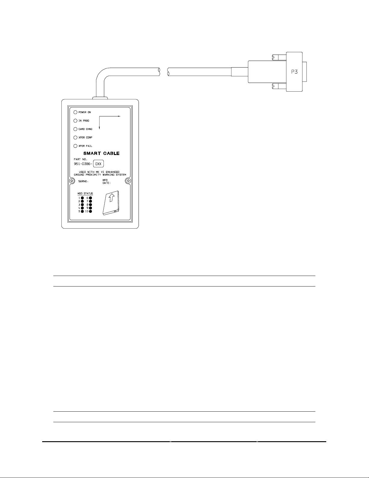
1.5.5 Smart Cable (PCMCIA Interface)
The EGPWS Smart Cable (part number 951-0386-001) is a removable PCMCIA card interface.
The Smart Card is compatible with any Honeywell supplied EGPWS PCMCIA style cards. The
purpose of the Smart Cable in the EGPWS system is for upload of software and databases and
also for download of EGPWS Flight History. The Smart Card loading operation will closely
emulate that of an ARINC 615 Data Loader.
CAGE CODE: 97896 SCALE: NONE SIZE: A DWG NO: 060-4314-225 REV: C
SHEET
20
Page 21
Honeywell
MK XXII EGPWS Installation Manual
FIGURE 1-1 MK XXII EGPWS SMART CABLE
1.6 Technical Characteristics
MK XXII EGPWS
TSO Compliance: TSO-C92c, TSO-C151a, class A
Physical size (HxWxD): 6.20” x 3.04” x 10.30”
Weight: 3.9 pounds maximum
Mounting: Standard 3 inch King Radio rack
Temperature (operational): -55°C to +70°C (F2)
Altitude range: 55,000 feet (F2)
Cooling: No cooling necessary
Shock: No shock mounting required
Power Consumption (28 VDC): 3 Amps
9 watts – no warning
+7 watts – with warning over 8 ohm speaker
+3 watts – with GPS card
+49 watts – with heater blanket on
Configuration Module
TSO Compliance: same as MK XXII EGPWS
CAGE CODE: 97896 SCALE: NONE SIZE: A DWG NO: 060-4314-225 REV: C
SHEET
21
Page 22

Honeywell
MK XXII EGPWS Installation Manual
Physical size: 2.68” x 1.51” x 0.32” (fits Positronic connector backshell)
Weight: <1 pound with connector and backshell
Mounting: Mounts to Positronic connector backshell
Temperature (operational): same as MK XXII EGPWS
Altitude range: same as MK XXII EGPWS
Cooling: No cooling necessary
Shock: No shock mounting required
Power Consumption (5 VDC): from MK XXII EGPWS
GPS Antenna Sensor
See Manufacturer’s specif ic at ions Ap pen dix D.
OAT Sensor
See Manufacturer’s specifications Appendix D.
1.7 Units Supplied
1.7.1 MK XXII EGPWS
The MK XXII EGPWS The part number for the units is as follows:
965-1590-0XX with Internal GPS card
note 1: -0XX defines the Application software version
1.7.2 Configuration Module
The MK XXII EGPWS Configuration Module is available in one version. When ordering the
Configuration Module, order part number 700-1710-001.
1.7.3 Smart Cable (PCMCIA Interface)
The MK XXII EGPWS Smart Cable is available in one version. The Smart Cable is used for Line
Maintenance, only one Smart Cable is required for an installation house or operator. When
ordering the Smart Cable, order part number 951-0386-001.
CAGE CODE: 97896 SCALE: NONE SIZE: A DWG NO: 060-4314-225 REV: C
SHEET
22
Page 23

Honeywell
MK XXII EGPWS Installation Manual
CAGE CODE: 97896 SCALE: NONE SIZE: A DWG NO: 060-4314-225 REV: C
SHEET
23
Page 24

Honeywell
MK XXII EGPWS Installation Manual
1.8 Installation and Accessories Kits
NOTE: Not all installation kits are immediately available, contact Honeywell Order
Administration (425-885-8719) for availability.
1.8.1 MK XXII EGPWS Installation Kits
(A) New EGPWS installation with OAT and Internal GPS
The MK XXII EGPWS Installation Kit #1, P/N 755-7013-001, contains the following parts:
Vendor Name Vendor P/N Description QTY UM Honeywell P/N
Positronic Ind. DD78F1OJVLC-15 P1 connector 1 EA 440-1158-009
Positronic Ind. RD50F1OJVLC-15 P2 connector 1 EA 440-1233-001
Amphenol 79075 GPS Antenna connector 1 EA 440-1239-0 01
Honeywell 700-1710-001 Configuration Module 1 EA 700-1710-001
Bendix/King 071-04003-0002 Computer Mounting Tray 1 EA 405-0383-001
CIC 05257 OAT Sensor 1 EA 107-1049-001
CIC 05257-TOMK OAT mounting Kit 1 EA 107-1049-002
CIC 05257-TPIK OAT Connector Kit 1 EA 107-1049-003
(B) New EGPWS installation with Internal GPS
The MK XXII EGPWS Installation Kit #5, P/N 755-7013-005, contains the following parts:
Vendor Name Vendor P/N Description QTY UM Honeywell P/N
Positronic Ind. DD78F1OJVLC-15 P1 connector 1 EA 440-1158-009
Positronic Ind. RD50F1OJVLC-15 P2 connector 1 EA 440-1233-001
Amphenol 79075 GPS Antenna connector 1 EA 440-1239-0 01
Honeywell 700-1710-001 Configuration Module 1 EA 700-1710-001
Bendix/King 071-04003-0002 Computer Mounting Tray 1 EA 405-0383-001
1.8.2 RS-232 Cable
The MK XXII EGPWS RS-232 Cable can be ordered using the following part numbers:
NOTE: The RS-232 Cable can be built by the Installer/Operator per the description in Section 4.4.2
Vendor Name Vendor P/N Description QTY UM Honeywell P/N
Honeywell 704-2617-001 RS-232 Cable 1 EA 704-2617-001
1.8.3 Smart Cable
The MK XXII EGPWS Smart Cable can be ordered using the following part numbers:
Vendor Name Vendor P/N Description QTY UM Honeywell P/N
Honeywell 951-0386-001 Smart Cable 1 EA 951-0386-001
CAGE CODE: 97896 SCALE: NONE SIZE: A DWG NO: 060-4314-225 REV: C
SHEET
24
Page 25

Honeywell
MK XXII EGPWS Installation Manual
1.8.4 Terrain Database Cards
The MK XII EGPWS Terrain Database Cards can be ordered using the following part numbers:
Vendor Name Vendor P/N Description QTY UM Honeywell P/N
Honeywell 424N AM North America 1 EA 718-1447-xxx
Honeywell 424 SA M South America 1 EA 718-1448-xxx
Honeywell 424EUR Europe 1 EA 718-1449-xxx
Honeywell 424EEU Eas tern Eur o pe 1 EA 718-1450-xxx
Honeywell 424AFR Africa 1 EA 718-1451-xxx
Honeywell 424PAC Pacific 1 EA 718-1452-xxx
Honeywell 424ASI Asia 1 EA 718-1453-xxx
Honeywell 424SP A South Pacific 1 EA 718-1457-xxx
Honeywell 424MES Middle East 1 EA 718-1458-xxx
Honeywell 402-6075-xxx Label, TDB Front Panel 1 EA 402-6075-xxx
1.8.5 Flight History Card
The Flight History Card is a PCMCIA card that has been loaded with a down load instruction file
to allow the down loading of flight history data from an EGPWS. Flight History files contain status
information, fault history and flight data from 20 seconds prior to 10 seconds after a EGPWS
caution or warning event. The card is used to aid in troubleshooting systems faults and or
nuisance warnings.
The MK XXII EGPWS Flight History Card can be ordered using the following part numbers:
Vendor Name Vendor P/N Description QTY UM Honeywell P/N
Honeywell * Flight History Download 1 EA *
* For flight history download cards call Honeywell GPWS Hotline 1 800 813-2099
1.9 Accessories Required but not Supplied
1.9.1 ARINC 453 Terrain Displ ay wiring
The Terrain display wiring (ARINC 453) must meet the display manufacturer’s specifications
including termination method. ARINC 453 buss wiring must meet the following requirements:
• Cable length must be less than 300 feet (91.4 meters).
• Wire to wire capacitance must not exceed 50 pF/foot.
• Shielded twisted pair with not less than one twist per inch.
• Impedance of 78 ohms ±10% at 1 MHz.
Vendor Name Vendor P/N Description QTY UM Honeywell P/N
Pic Wire&Cable D620224 ARINC 453 cable A/R EA
Pic Wire&Cable D5102QX Hi Temp Quadraxial A/R EA
Pic Wire&Cable D771553 MIL-STD 1553 Data Bus A/R EA
ECS 4122021 ARINC 453 cable A/R EA
CAGE CODE: 97896 SCALE: NONE SIZE: A DWG NO: 060-4314-225 REV: C
SHEET
25
Page 26

Honeywell
MK XXII EGPWS Installation Manual
Vendor Name Vendor P/N Description QTY UM Honeywell P/N
Emteq D 07002-100 ARINC 453 Cable A/R EA
M17/176-00002 M ilitary Specification A/R EA
1.9.2 GPS Antenna & cable
The GPS Antenna & cable can be ordered from their manufacturers using the following part
numbers:
Vendor Name Vendor P/N Description QTY UM Honeywell P/N
Bendix/King 071-01545-0200 KA 91 GPS Antenn a 1 EA
Bendix/King 071-01553-0200 KA 92 GPS Antenn a 1 EA 300-1147-001
Comant CI 405-2 KA 92 GPS Antenna 1 EA 300-1147-001
Bendix/King 050-03318-0000 Antenna Installation Kit OPT EA 405-0432-001
Sensor Systems
Sensor Systems
Sensor Systems
Thermax M17/128-RG400 Coax Cable, RG400 A/R EA
Amp 225554-6 TNC Angle Plug, Male 1 EA 440-1239-001
Amphenol 79075 TNC Angle Plug, Male 1 EA 440-1239-001
S67-1575-38 S67 GPS Antenna 1 EA
S67-1575-52 S67 GPS Antenna 1 EA
S67-1575-133 S67 GPS Antenna 1 EA
Coax Cable, RG-142 A/R EA
1.9.3 Circuit Breaker
The Circuit Breaker needs to be a 3 Amp delayed action circuit breaker.
Vendor Name Vendor P/N Description QTY UM Honeywell P/N
Klixon (T.I.) 7277-2-3 3 Amp Circuit Breaker,
EGPWS power +28
Klixon (T.I.) 7277-2-1 1 Amp Circuit Breaker,
lamp power +28
1EA
1EA
1.9.4 Annunciators & Switch/Annunciators
The devices shown below are switch/annunciators and are representative of those used in some
installations. The installer/customer is cautioned to verify regulatory approval of the annunciation
devices installed. See Appendix D for Vendors.
1.9.4.1 GPWS Warning (red) P/TES T; s wi tch/a nnuncia tor assem bly
The ‘GPWS’ annunciator provides visual indication of an EGPWS alert. The GPWS warning (red)
annunciator also has a switch that is used to manually initiate EGPWS Self Test.
CAGE CODE: 97896 SCALE: NONE SIZE: A DWG NO: 060-4314-225 REV: C
SHEET
26
Page 27

Honeywell
MK XXII EGPWS Installation Manual
1.9.4.2 GPWS Caution (amber) G/S C ANCLD switch/annunciator assembly.
The ‘GPWS caution annunciator provides visual indication of an EGPWS alert. The EGPWS
caution (amber) annunciator also has a switch that is used to manually inhibit EGPWS Mode 5
glideslope alerts. The bottom half of the annunciator provides visual indication that the mode 5
glideslope alerts have been canceled.
1.9.4.3 LOW ALT / ON switch/annunciator assembly
The LOW ALT / ON switch/annunciator provides for manual selection of low altitude mode and
visual indication that the Mk XXII EGPWS is in low altitude mode.
1.9.4.4 TERR INHIB / ON switch/annunciator assembly
The ‘TERR INHIBIT’ switch/annunciator provides for manual selection of terrain inhibit mode and
visual indication that the EGPWS Terrain functions have been inhibited.
1.9.4.5 AUDIO INHIBIT / ON switch/annunciator assembly
The ‘AUDIO INHIBIT’ switch/annunciator provides for manual selection of audio inhibit mode and
visual indication that the EGPWS mode 6 functions have been inhibited.
1.9.4.6 GPWS INOP / TERR INOP annunciator assemblies
The ‘GPWS INOP’ annunciator provides visual indication that the EGPWS GPWS modes have a
disabled function.
The ‘TERR INOP’ annunciator provides visual indication that the EGPWS Terrain modes have a
disabled function.
1.9.4.7 TERR DISPLAY / ON switch/annunciator assemblies
The ‘TERR DISPLAY’ switch/annunciator provides for manual selection of the terrain display and
visual indication that the EGPWS Terrain Display has been selected for the associated display.
1.10 Cockpit Speaker (Optional)
The MK XXII EGPWS can interface to an 8 ohm audio speaker for cockpit annunciation of aural
alerts.
Vendor Name Vendor P/N Description QTY UM Honeywell P/N
Quam 30A05Z8 Audio Sp eaker 1 EA
Utah SP-3A Audio Speaker 1 EA
CTS 4AC3 Audio Speaker 1 EA 300-0218-002
CAGE CODE: 97896 SCALE: NONE SIZE: A DWG NO: 060-4314-225 REV: C
SHEET
27
Page 28

Honeywell
MK XXII EGPWS Installation Manual
1.11 Tools Required
1.11.1 Crimping Tool - P1, P2, P3
Description UM QTY Vendor Name & Part Number
Hand Crimping Tool EA 1 Positronic Ind. 9507
Hand Crimping Tool EA 1 Daniels AFM8
Hand Crimping Tool EA 1 Military M22520/2-1
1.11.2 Contact Positioner - P1, P2, P3
Description UM QTY Vendor Name & Part Number
Contact Positioner, Sock et P1 EA 1 Positronic Ind. 9502-3
Contact Positioner, Socket P1 EA 1 Daniels K41 (for 22 to 28 AWG)
Contact Positioner, Socket P1 EA 1 Military M22520/2-06
Contact Positioner, Sock et P2 EA 1 Positronic Ind. 9502-5
Contact Positioner, Socket P2 EA 1 Daniels K13-1 (20-24 AWG)
Contact Positioner, Socket P2 EA 1 Military M22520/2-08
Contact Positioner, Pin P3 EA 1 Positronics 9502-4
Contact Positioner, Pin P3 EA 1 Daniles K42 (22-28 AWG)
Contact Positioner, Pin P3 EA 1 Military M22520/2-09
1.11.3 Insertion/Removal Tool - P1, P2, P3
Description UM QTY Vendor Name & Part Number
Removal Tool P1, P3 EA 1 Daniels DRK 95-22M
Removal Tool P1, P3 EA 1 Military M81969/8-02
Removal Tool P2 EA 1 Daniels DRK145
Insertion Tool P1, P3 EA 1 Daniels DAK 95-22M
Insertion Tool P1, P3 EA 1 Military M81969/8-01
Insertion Tool P2 EA 1 Daniels DAK145
Insertion/Removal T ool P1, P3 EA 1 Military M81969/1-04
Insertion/Removal Tool P2 EA 1 Military M81969/1-02
1.11.4 Spare Contacts - P1, P2, P3
Description Mil Spec Part Number
Contacts (P1) socket M39029/57-354 22-28 GA Wire
Contacts (P2) socket M39029/63-368 20-24 GA Wire
Contacts (P3) Pin M39029/58-360 22-28 GA Wire
1.12 License Requirements
There are no Radio license requirements for the MK XXII EGPWS.
CAGE CODE: 97896 SCALE: NONE SIZE: A DWG NO: 060-4314-225 REV: C
SHEET
28
Page 29

Honeywell
MK XXII EGPWS Installation Manual
CAGE CODE: 97896 SCALE: NONE SIZE: A DWG NO: 060-4314-225 REV: C
SHEET
29
Page 30

Honeywell
MK XXII EGPWS Installation Manual
SECTION II
INSTALLATION
CAGE CODE: 97896 SCALE: NONE SIZE: A DWG NO: 060-4314-225 REV: C
SHEET
30
Page 31

Honeywell
MK XXII EGPWS Installation Manual
CAGE CODE: 97896 SCALE: NONE SIZE: A DWG NO: 060-4314-225 REV: C
SHEET
31
Page 32

Honeywell
MK XXII EGPWS Installation Manual
SECTION II – INSTALLATION
SECTION II - INSTALLATION .............................................................................................................................. 33
2.1 I
NTRODUCTION.................................................................................................................................................... 33
2.2 U
NPACKING AND INSPECTING THE EQUIPMENT................................................................................................... 33
2.3 E
QUIPMENT INSTALLATION ................................................................................................................................. 33
2.3.1 General........................................................................................................................................................33
2.3.2 MK XXII Computer Location....................................................................................................................... 34
2.3.3 MK XXII Computer Installation...................................................................................................................34
2.3.4 Configuration Module Location .................................................................................................................. 35
2.3.5 Configuration Module Installation.............................................................................................................. 35
2.3.6 GPS Antenna location.................................................................................................................................. 44
2.3.7 GPS Antenna Installation............................................................................................................................ 44
2.3.8 OAT Sensor Location................................................................................................................................... 44
2.3.9 OAT Sensor Installation...............................................................................................................................44
2.3.10 Cockpit Annunciators / Switches................................................................................................................44
2.3.10.1 Description............................................................................................................................................................ 45
2.3.10.2 Location ................................................................................................................................................................ 46
2.3.10.3 Inhibit Switch Functions and Selection................................................................................................................. 48
2.3.10.3.1 Terrain Inhibit................................................................................................................................................ 48
2.3.10.3.2 Audio Inhibit (Timed).................................................................................................................................... 48
2.3.10.3.3 Audio Inhibit (Not Described Above)............................................................................................................ 48
2.3.10.3.4 Low Altitude Mode........................................................................................................................................ 48
CAGE CODE: 97896 SCALE: NONE SIZE: A DWG NO: 060-4314-225 REV: C
SHEET
32
Page 33

Honeywell
MK XXII EGPWS Installation Manual
SECTION II - INSTALLATION
2.1 Introduction
This section contains suggestions and factors to consider before installing the Enhanced Ground Proximity
Warning System. Close adherence to these suggestions will assure satisfactory performance from the
equipment.
NOTE
The conditions and tests performed on this article are minimum performance
standards. It is the responsibility of those desiring to install this article either on or
within a specific type or class of aircraft to determine that the aircraft installation
conditions are within these performance standards. The article may be installed only if
further evaluation by the applicant documents an acceptable installation and is
approved by the Administrator.
2.2 Unpacking and Inspecting the Equipment
Exercise extreme caution when unpacking equipment. Perform a visual inspection of the unit for evidence
of damage incurred during shipment. If a damage claim must be filed then save the shipping container and
all packing materials to substantiate your claim. The claim should be filed as soon as possible. The
shipping container and all packing materials should be retained in the event that storage or reshipment of
the equipment is necessary.
2.3 Equipment Installation
2.3.1 General
The following paragraphs contain information pertaining to the installation of the MK XXII EGPWS,
including instructions concerning the location and mounting of the equipment. The equipment should be
installed in the aircraft in a manner consistent with acceptable workmanship and engineering practices,
and in accordance with the instructions set forth in this publication. To ensure the system has been
properly and safely installed in the aircraft, the installer should make a thorough visual inspection and
conduct an overall operational check of the system, on the ground, prior to flight.
CAUTION
AFTER INSTALLATION OF THE CABLING AND BEFORE INSTALLATION OF THE
EQUIPMENT, A CHECK SHOULD BE MADE WITH THE AIRCRAFT PRIMARY POWER
SUPPLIED TO THE MOUNTING CONNECTOR, TO ENSURE THAT POWER IS
APPLIED ONLY TO THE PINS SPECIFIED IN THE INTERWIRING DIAGRAMS IN
SECTION III.
CAGE CODE: 97896 SCALE: NONE SIZE: A DWG NO: 060-4314-225 REV: C
SHEET
33
Page 34

Honeywell
MK XXII EGPWS Installation Manual
2.3.2 MK XXII Computer Location
Care should be exercised to avoid mounting components near equipment operating with high pulse current
or high power outputs such as radar and satellite communications equipment. In general, the equipment
should be installed in a location convenient for operation, inspection, and maintenance, and in an area free
from excessive vibration, heat, and noise generating sources.
The MK XXII EGPWS has an internal heater blanket therefore they can be mounted outside the heated
area of the aircraft. The computers have been qualified for operation up to 50,000 feet and -55°C using the
heater blanket.
All mechanical installation drawings, connector assembly diagrams, interwiring diagrams, and connector
pin assignment tables referenced in this section are located at the end of Section II, of the manual.
Determine the mounting location for the system components following the guidelines below.
The length of cables from the EGPWS connectors to other system units is not generally critical because
unit interfaces are designed with high impedance inputs, low impedance outputs, and low noise
susceptibility characteristics. The exception is the wires from the EGPWS Configuration Module, which
was designed to be a part of the EGPWS connector backshell because of the requirement for short lead
length.
To allow for inspection or repair of the wiring of the connector assembly itself, sufficient lead length should
be left so that EGPWS may be moved several inches. A bend should be made in the harness to allow
water droplets that might form on the harness due to condensation, to drip off at the bend and not collect in
the connector.
Prior to installing any equipment, make a continuity check of all wires and cables associated with the
system. Then apply power and check for proper voltages at system connectors, and then remove power
before completing the installation.
2.3.3 MK XXII Computer Installation
The MK XXII EGPWS installation will conform to standards designated by the customer, installing agency,
and existing conditions as to the unit location and type of installation. However, the following suggestions
will assure a more satisfactory performance from the equipment.
A. Plan a location on the aircraft so that the EGPWS is accessible for front panel maintenance controls.
Check to be sure that there is adequate space in the front of the computer for connectors and cabling.
B. Refer to Figure 2-2 and 2-3 for outline dimensions of the computer and mounting tray.
C. Mount the EGPWS mounting tray in the aircraft radio rack or other location using the four screw
mounting holes. Match drill the mounting holes using the Mounting Tray as a template.
D. Ensure that the mounting tray is electrically bonded (less than 10 milli-ohm to aircraft ground).
CAGE CODE: 97896 SCALE: NONE SIZE: A DWG NO: 060-4314-225 REV: C
SHEET
34
Page 35

Honeywell
MK XXII EGPWS Installation Manual
E. Slide the EGPWS unit in the mounting tray, and secur e it us ing the Hold Down latc h.
F. (After Continuity and Power check) Attach the cable harness to the front panel connectors and lock
connectors using the slide lock of the P1 & P2 connectors. The EGPWS should be wired according to
the interconnect diagrams in Section III, of this manual.
2.3.4 Configuration Module Location
The aircraft configuration is programmed into the EGPWS Configuration Module installed in the aircraft
wiring. The Configuration Module is identified as Honeywell part number 700-1710-001. The Configuration
Module is installed as one side of the P2 (50 pin) mating connector backshell and contains electrically
reprogrammable memory for configuration storage. The Configuration Module when installed is wired
directly to the appropriate pins in the P2 connector.
2.3.5 Configuration Module Installation
The purpose of this procedure is to give an assembly sequence for assembly of the Configuration Module
with the P2 connector and backshell.
A. The P2 connector, Honeywell part number 440-1233-001, vendor part number RD50F1OJVLC-15,
when ordered comes with 50 contacts and a plastic backshell (hood).
B. The Configuration Module will replace the Backshell Plate. The Backshell Plate can be discarded.
C. Wire the Configuration Module to the P2 connector using contacts provided with the connector. Wire
per the following wire list:
Wire Color P2 pin #
Violet P2-17
Blue P2-16
Orange P2-33
Wire Color P2 pin #
Black P2-50
White P2-49
Red P2-32
CAGE CODE: 97896 SCALE: NONE SIZE: A DWG NO: 060-4314-225 REV: C
SHEET
35
Page 36

Honeywell
MK XXII EGPWS Installation Manual
D. Position Slide Lock and Spring Clip onto connector.
E. Install Backshell Housing onto connector. The Ground wire (used for ESD discharge) is terminated
with shielded pigtails inside the backshell to the P2 connector.
F. Organize and dress wire exiting from the backshell, route Configuration Module wires in a coil. Install
Cable Clamp, do not tighten Cable Clamp screws.
G. Secure the Configuration Module to the connector using screws provided. Tighten Cable Clamp
screws as required.
CONFIGURATION MODULE ASSEMBLY
REQUIRED: Two items as follows:
ITEM 1.0 Connector (P2) Positronic Ind. RD50F10JVLC-15 *
ITEM 2.0 Configuration Module Honeywell 700-1710-001
* This item may be available from Honeywell under Part No. (440-1233-001)
ITEM 1 DESCRIPTION:
Connector P2 (Positronic Ind. PN RD50F10JVLC-15) is a packaged kit consisting of the following parts:
1.1 Connector, 50 socket D-Sub Qty - 1
1.2 Contacts, size 20 crimp Qty - 50
1.3 Backshell housing Qty - 1
1.4 Backshell plate Qty - 1
1.5 Screws, Phillips CSK Qty - 2
1.6 Spring Clip Qty - 1
1.7 Slide Lock Qty - 1
1.8 Screws, Slotted Qty - 2
1.9 Cable Clamp Qty - 1
CAGE CODE: 97896 SCALE: NONE SIZE: A DWG NO: 060-4314-225 REV: C
SHEET
36
Page 37

Honeywell
MK XXII EGPWS Installation Manual
INSTALLATION ASSEMBLY SEQUENCE
STEP 1 Install all MK XXII system aircraft wiring to this connector using items 1.2 (Crimp Contacts)
and item 1.1 (Connector). See figure 2-1.1 below.
FIGURE 2-1.1 MK XXII EGPWS CONFIGURATION MODULE
CAGE CODE: 97896 SCALE: NONE SIZE: A DWG NO: 060-4314-225 REV: C
SHEET
37
Page 38

Honeywell
MK XXII EGPWS Installation Manual
STEP 2 Wire item 2.0 (Configuration Module). This part will replace item 1.4 (Backshell plate).
Install the pre-crimped colored wires into item 1.1 (Connector) as shown in figure 2-1.2
below.
FIGURE 2-1.2 MK XXII EGPWS CONFIGURATION MODULE
CAGE CODE: 97896 SCALE: NONE SIZE: A DWG NO: 060-4314-225 REV: C
SHEET
38
Page 39

Honeywell
MK XXII EGPWS Installation Manual
STEP 3 Position item 1.7 (Slide lock) onto wired connector as shown in figure 2-1.3 below:
FIGURE 2-1.3 MK XXII EGPWS CONFIGURATION MODULE
CAGE CODE: 97896 SCALE: NONE SIZE: A DWG NO: 060-4314-225 REV: C
SHEET
39
Page 40

Honeywell
MK XXII EGPWS Installation Manual
STEP 4 Install item 1.3 (Backshell Housing) onto connector using item 1.8 (Screws) as shown in
figure 2-1.4 below:
Ground Wire (used for electrostatic discharge {ESD} protection) is terminated with
shielded pigtails of wires at this connector.
FIGURE 2-1.4 MK XXII EGPWS CONFIGURATION MODULE
CAGE CODE: 97896 SCALE: NONE SIZE: A DWG NO: 060-4314-225 REV: C
SHEET
40
Page 41

Honeywell
MK XXII EGPWS Installation Manual
STEP 5 Install item 1.6 (Spring Clip) as shown figure 2-1.5 below:
FIGURE 2-1.5 MK XXII EGPWS CONFIGURATION MODULE
CAGE CODE: 97896 SCALE: NONE SIZE: A DWG NO: 060-4314-225 REV: C
SHEET
41
Page 42

Honeywell
MK XXII EGPWS Installation Manual
STEP 6 Organize and dress wiring exiting from backshell. Route Configuration Module wires
exiting from connector, then coil as shown in figure 2-1.6 below. Install item 1.9 (Cable
Clamp) as shown. Do not tighten screws yet.
FIGURE 2-1.6 MK XXII EGPWS CONFIGURATION MODULE
CAGE CODE: 97896 SCALE: NONE SIZE: A DWG NO: 060-4314-225 REV: C
SHEET
42
Page 43

Honeywell
MK XXII EGPWS Installation Manual
STEP 7 Secure Configuration Module to connector assembly using item 1.5 (Screws) as shown in
figure 2-1.7 below. Tighten Cable Clamp screws as required.
FIGURE 2-1.7 MK XXII EGPWS CONFIGURATION MODULE
CAGE CODE: 97896 SCALE: NONE SIZE: A DWG NO: 060-4314-225 REV: C
SHEET
43
Page 44

Honeywell
MK XXII EGPWS Installation Manual
2.3.6 GPS Antenna location
The antenna must be mounted on top of the fuselage. Avoid mounting the antenna near any projections
such as the rotor mast, or engine exhaust, where shadows could occur or high heat could damage the
antenna. It is recommended that there be a separation of at least 3 feet between the GPS antenna and
any VHF Comm antenna on the aircraft. The antenna baseplate must be level within ± 5° in both axis
when the aircraft is level (level is defined as the aircraft attitude required when weighing the aircraft for
weight and balance). If the antenna is tilted more than 5° or is mounted close to other objects that shadow
it, loss of some of the satellites will occur and system performance may be degraded. See manufacturer’s
drawing in Appendix D for specifications of antenna, antenna cables, and connector information.
2.3.7 GPS Antenna Installation
Refer to manufacturer’s procedures or applicable STC documentation.
2.3.8 OAT Sensor Location
The OAT sensor (CIC 05257) should be mounted on the underside (belly) of the aircraft or other
convenient location meeting the following conditions. Avoid mounting the sensor where it can be affected
by direct sunlight, or exhaust gases from engines or heaters. The probe tip should extend beyond the
aircraft boundary layer into the turbulent airflow. See manufacturer’s drawing in Appendix D for
specifications.
2.3.9 OAT Sensor Installation
Refer to manufacturer’s procedures or applicable STC documentation.
2.3.10 Cockpit Annunciators / Switches
This section provides information for selecting, locating and mounting of the MK XXII EGPWS Lighted
annunciators / switches. NOTE: The nomenclature given for each lamp is an example only. Other
manufacturers use nomenclature that is also acceptable. Refer to Honeywell Product Specification 9651590-601 for additional information and for electrical loads specification
CAGE CODE: 97896 SCALE: NONE SIZE: A DWG NO: 060-4314-225 REV: C
SHEET
44
Page 45

Honeywell
MK XXII EGPWS Installation Manual
2.3.10.1 Description
EGPWS warning GPWS P/TEST
This assembly is illuminated with Red background and black or white letters. For dark cockpits black
background and Red letters. The EGPWS warning annunciator is not normally dimmable. For Lamp
Format 1 (I/O Discrete Type 128) the lamp is activated during any Mode 1 through Mode 4, and Terrain
/Obstacle Awareness alerts and warnings. For Lamp Format 2 (I/O Discrete Type 129) the lamp is
activated during Mode 1 and Mode 2 Pull Up, and Terrain /Obstacle Awareness warnings. This assembly
also includes a momentary switch that will activate EGPWS Self Test.
EGPWS caution GPWS G/S CANCLD
This assembly is illuminated with Amber background and black or white letters, for dark cockpits black
background and Amber letters. The EGPWS alert annunciator is not normally dimmable. For Lamp Format
1 (I/O Discrete Type 128) the lamp is activated during any Mode 5 alert. For Lamp Format 2 (I/O Discrete
Type 129) the lamp is activated during any Mode 1 through Mode 4, and Terrain /Obstacle Awareness
alerts. This assembly also includes a momentary switch that will activate glideslope cancel.
LOW ALTITUDE LOW ALT ON
This assembly is illuminated with black background and white, green, or blue letters. This assembly also
includes a momentary switch that will activate / de-activate (cancel) EGPWS low altitude mode.
TERRAIN INHIBIT TERR INHIB ON
This assembly is illuminated with black background and white, blue, or green letters. This assembly also
includes a alternate action switch that will activate ./ de-activate (cancel) Terrain inhibit mode. (Optional
see section 2.3.10.3)
AUDIO INHIBIT AUDIO INHIB ON
This assembly is illuminated with black background and white, blue, or green letters This assembly also
includes a momentary switch that will activate ./ de-activate (cancel) Audio inhibit mode. (Optional see
section 2.3.10.3)
GPWS system validity GPWS INOP TERR INOP
This assembly is illuminated with black background and amber letters activated during any detected partial
or total failure of the GPWS modes 1-5. And TA&D
TERRAIN select TERR DISPLAY ON
This assembly is illuminated with white background and activated af ter the flight crew has initiated the
manual selection of the EGPWS terrain display for the associated cockpit display. This assembly also
includes a momentary switch that will activate EGPWS Terrain display feature.
CAGE CODE: 97896 SCALE: NONE SIZE: A DWG NO: 060-4314-225 REV: C
SHEET
45
Page 46

Honeywell
MK XXII EGPWS Installation Manual
2.3.10.2 Location
Cockpit layout, size and operator’s preference will determine if only one set of lights is used (i.e., mounted
in the center), or if dual sets of lights are used (one set on each side), or a combination thereof is desired.
For a typical example of cockpit light locations refer to Figure 2-7. For panel cutouts and assembly options
see the manufacturer’s specifications in Appendix D. The following are recommended locations:
GPWS warning (red) & GPWS alert (amber)
These lights should be located together and in the flight crew’s “primary field of view”. This would include
either the instrument panel or the edge of the glareshield.
LOW ALTITUDE
This light should be located in the flight crew’s “field of view” and within reach of both crewmembers. This
light/switch may be located in an assembly with the GPWS red and GPWS amber lights and/or other
EGPWS annunciators.
TERR INHIBIT ON (Optional see section 2.3.10.3)
This light should be located in the flight crew’s “field of view” and within reach of both crewmembers. This
light/switch may be located in an assembly with the TERR DISPLAY light(s) and/or other EGPWS
annunciators.
AUDIO INHIBIT ON (Optional see section 2.3.10.3)
This light should be located in the flight crew’s “field of view” and within reach of both crewmembers. This
light/switch may be located in an assembly with the TERR DISPLAY light(s) and/or other EGPWS
annunciators.
TERR DISPLAY ON
This light should be located near the associated cockpit display, in the flight crew’s “field of view” and
within reach of one or both crewmembers. This light/switch may be located in an assembly with the TERR
INHIBIT light(s) and/or other EGPWS annunciators.
GPWS INOP
This light should be located within crewmember’s “field of view” or with other system INOP lights of similar
importance. It is recommended that this light not be located in the flight crew’s “primary field of view”. The
reason being that in the event of a GPWS system failure at the beginning of a flight, this light will remain
“ON” until the problem is fixed.
TERR INOP
This light should be located within at least one crewmember’s “field of view” or with other system INOP
lights of similar importance. Note: Annunciators are available with split legend GPWS INOP / TERR INOP
in one assembly. It is recommended that this light not be located in the flight crew’s “primary field of view”.
The reason being that in the event of a GPWS system failure at the beginning of a flight, this light will
remain “ON” until the problem is fixed.
CAGE CODE: 97896 SCALE: NONE SIZE: A DWG NO: 060-4314-225 REV: C
SHEET
46
Page 47

Honeywell
MK XXII EGPWS Installation Manual
FIGURE 2-1.8 MK XXII EGPWS Annunciators/Switches Location
CAGE CODE: 97896 SCALE: NONE SIZE: A DWG NO: 060-4314-225 REV: C
SHEET
47
Page 48

Honeywell
MK XXII EGPWS Installation Manual
2.3.10.3 Inhibit Switch Functions and Selection
The Terrain Inhibit and Audio Inhibit functions are optional but it is recommended that one be used to
inhibit the system during certain operations. The operator should evaluate the two options together with
the Low Altitude Mode function and select the one that best fits his operational requirements. The Low
Altitude Mode is also described below for reference.
2.3.10.3.1 Terrain Inhibit
The Terrain Inhibit will inhibit Terrain and Obstacle audio alerts and warnings. It will not deselect the
Terrain Display. The switch is a toggle action, which must be pressed to turn ON and re-pressed to turn
OFF. The switch lighting must be activated thru the switch contacts. This Inhibit is recommended for
corporate transport operations.
2.3.10.3.2 Audio Inhibit (Timed)
The Timed Audio Inhibit will inhibit all audio output for a period of 5 minutes. It will not affect visual alert
and warning outputs and will not deselect the terrain display. The switch is momentary and the lamp is
illuminated by an output from the EGPWS. This inhibit is recommended for EMS and SAR operations.
2.3.10.3.3 Audio Inhibit (Not Described Above)
The Audio Inhibit will inhibit all audio output as long as it is active. It will not affect visual alert and warning
outputs and will not deselect the terrain display. The switch is a toggle action, which must be pressed to
turn ON and re-pressed to turn OFF. The switch lighting must be activated thru the switch contacts. This
Inhibit is NOT RECOMMENTED.
2.3.10.3.4 Low Altitude Mode
To allow for helicopter operations that require low altitude flight a Low Altitude function is enabled with a
switch. This function is designed for flight at low altitude in VFR conditions. When this function is engaged
Mode 2 and Mode 4 warning boundaries are significantly reduced and Terrain Advisory look ahead
distances are reduced. . Low Altitude operation is defined as operation below 500 feet AGL. There are
other circumstances where the use of the Low Altitude Mode is appropriate. Those include operation in a
high-density metropolitan environment with high rise buildings, operation below 1250 feet AGL when the
GPS is not operational or is providing poor accuracy.
CAGE CODE: 97896 SCALE: NONE SIZE: A DWG NO: 060-4314-225 REV: C
SHEET
48
Page 49

Honeywell
MK XXII EGPWS Installation Manual
FIGURE 2-2 MK XXII EGPWS OUTLINE
CAGE CODE: 97896 SCALE: NONE SIZE: A DWG NO: 060-4314-225 REV: C
SHEET
49
Page 50

Honeywell
MK XXII EGPWS Installation Manual
FIGURE 2-3 MK XXII EGPWS MOUNTING TRAY
Honeywell P/N
405-0383-001
CAGE CODE: 97896 SCALE: NONE SIZE: A DWG NO: 060-4314-225 REV: C
SHEET
50
Page 51

Honeywell
MK XXII EGPWS Installation Manual
CAGE CODE: 97896 SCALE: NONE SIZE: A DWG NO: 060-4314-225 REV: C
SHEET
51
Page 52

Honeywell
MK XXII EGPWS Installation Manual
SECTION III
SYSTEM PLANNING
CAGE CODE: 97896 SCALE: NONE SIZE: A DWG NO: 060-4314-225 REV: C
SHEET
52
Page 53

Honeywell
MK XXII EGPWS Installation Manual
CAGE CODE: 97896 SCALE: NONE SIZE: A DWG NO: 060-4314-225 REV: C
SHEET
53
Page 54

Honeywell
MK XXII EGPWS Installation Manual
SECTION III – SYSTEM PLANNING
SECTION III – SYSTEM PLANNING..................................................................57
3.1 INTRODUCTION.................................................................................................................................... 57
3.2 S
YSTEM WIRING/ ELECTRICAL INTERFACES........................................................................................57
3.2.1 Primary Power Input...................................................................................................... ............. 57
3.2.2 Chassis Ground ........................................................................................................................... 57
3.2.3 GPS Antenna................................................................................................................................ 58
3.2.4 Analog and Digital Inputs............................................................................................................58
3.2.5 Discrete Inputs............................................................................................................................. 58
3.2.6 Serial Outputs.............................................................................................................................. 58
3.2.7 Audio Output................................................................................................................................ 59
3.2.8 Discrete Outputs.......................................................................................................................... 59
3.2.9 Configuration Module ................................................................................................................. 59
3.3 C
ONFIGURABLE INTERFACES............................................................................................................... 60
3.3.1 Category 1 - Aircraft / Mode Type Select.................................................................................... 60
3.3.1.1 Aircraft / Mode Type............................................................................................................................. 60
3.3.1.2 Instructions............................................................................................................................................ 60
3.3.1.3 Generic Helicopter with and without Torque......................................................................................... 60
3.3.2 Category 2 – Air Data Input Select..............................................................................................61
3.3.2.1 Instructions............................................................................................................................................ 61
3.3.2.2 Examples............................................................................................................................................... 62
3.3.2.3 Analog altitude and 500 ohm OAT................................................................................................... 62
3.3.2.4 Digital – ARINC 429 (Cat. 2 ID 5, 1, 6)........................................................................................... 63
3.3.2.5 Digital –ARINC 575 (Cat. 2 ID 2).................................................................................................... 64
3.3.2.6 Shadin 2000 (Cat. 2 ID 10) ............................................................................................................... 65
3.3.2.7 Digital – ARINC 429 Dual IOC Buses (Cat. 2. ID 255)................................................................... 66
3.3.3 Category 3 – Position Input Select.............................................................................................. 67
3.3.3.1 Instructions............................................................................................................................................ 67
3.3.3.2 ARINC 743 Format ............................................................................................................................... 67
3.3.3.Examples.................................................................................................................................................. 68
3.3.3.1 ARINC 429 BUS (Cat. 3 ID 0,1,4,5)................................................................................................. 68
3.3.3.2 RS-232 Transmit-Receive, 9600 baud (Cat. 3 ID 3) ......................................................................... 68
3.3.3.3 Dual ARINC 429 BUS (Cat. 3 ID 255)............................................................................................. 69
3.3.4 Category 4 – Altitude Callouts ....................................................................................................70
3.3.4.1 Instructions............................................................................................................................................ 70
3.3.5 Category 5 – Audio Menu Select................................................................................................. 71
3.3.5.1 Instructions............................................................................................................................................ 71
3.3.6 Category 6 – Terrain Display Select ...........................................................................................72
3.3.6.1 Instructions............................................................................................................................................ 72
3.3.6.2 TAD Selection....................................................................................................................................... 72
CAGE CODE: 97896 SCALE: NONE SIZE: A DWG NO: 060-4314-225 REV: C
SHEET
54
Page 55

Honeywell
MK XXII EGPWS Installation Manual
3.3.6.3 Terrain Display Configuration Group.................................................................................................... 73
3.3.6.4 Display Input Control Group............................................................................................ ..................... 75
3.3.6.5 Output 429 Bus Group........................................................................................................................... 75
3.3.6.6 Example................................................................................................................................................. 75
3.3.7 Category 7 – Options Select Group #1........................................................................................ 81
3.3.7.1 Instructions............................................................................................................................................ 81
3.3.7.2 Steep Approach (Not Available in the Mk XXII).................................................................................. 81
3.3.7.3 TA&D Alternate Pop-up........................................................................................................................ 81
3.3.7.4 Peaks Mode ........................................................................................................................................... 82
3.3.7.5 Obstacle Awareness............................................................................................................................... 82
3.3.7.6 Bank Angle Callout Enabling................................................................................................................ 82
3.3.7.8 WOW Reversal...................................................................................................................................... 83
3.3.7.9 GPS Altitude Reference......................................................................................................................... 83
3.3.8 Category 8 – Radio Altitude Input Select .................................................................................... 84
3.3.8.1 Instructions............................................................................................................................................ 84
3.3.8.2 Example................................................................................................................................................. 84
3.3.8.3 Digital Radio Altitude Interface........................................................................................................ 84
3.3.8.4 Analog Radio Altitude Interface........................................................................................................ 85
3.3.9 Category 9 – Navigation Inputs Select........................................................................................ 86
3.3.9.1 Instructions............................................................................................................................................ 86
3.3.9.2 Example................................................................................................................................................. 87
3.3.9.3 Analog Glideslope Interface (cat. 9 ID 0,1,5) ................................................................................... 87
3.3.9.4 Digital Glideslope/Localizer Interface.............................................................................................. 88
3.3.9.5 Dual Glideslope Receiver.................................................................................................................. 88
3.3.10 Category 10 – Attitude Input Select........................................................................................... 89
3.3.10.1 Attitude Signals ................................................................................................................................... 89
3.3.10.2 Instructions.......................................................................................................................................... 89
3.3.10.3 Example............................................................................................................................................... 90
3.3.10.4 Analog Roll Angle (Synchro).......................................................................................................... 90
3.3.10.5 Digital ARINC 429 High Speed...................................................................................................... 91
3.3.11 Category 11 – Heading Input Select.......................................................................................... 92
3.3.11.1 Instructions.......................................................................................................................................... 92
3.3.11.2 Magnetic Heading................................................................................................................................ 92
3.3.11.3 Example............................................................................................................................................... 93
3.3.11.3.1 Analog Heading (Synchro) (CAT. 11 ID 0)................................................................................. 93
3.3.11.3.2 Digital ARINC 429 High Speed........................................................................................ ........... 94
3.3.12 Category 12 – Windshear Input Select ...................................................................................... 95
3.3.12.1 Instruction............................................................................................................................................ 95
3.3.13 Category 13 – Input / Output Discrete Type Select...................................................................96
3.3.13.1 Instruction............................................................................................................................................ 96
3.3.13.2 Input/Output Discretes......................................................................................................................... 96
3.3.13.3 Audio Inhibit Discrete..................................................................................................................... 97
3.3.13.4 Landing Gear Discrete..................................................................................................................... 97
CAGE CODE: 97896 SCALE: NONE SIZE: A DWG NO: 060-4314-225 REV: C
SHEET
55
Page 56

Honeywell
MK XXII EGPWS Installation Manual
3.3.13.5 Weight ON Wheels (WOW) Discrete............................................................................................. 97
3.3.13.6 Glideslope Cancel Discrete............................................................................................................. 98
3.3.13.7 Mode 6 Low Volume Discrete........................................................................................................ 98
3.3.13.8 Autopilot Engaged Discrete ............................................................................................................ 98
3.3.13.9 Terrain Awareness Inhibit............................................................................................................... 99
3.3.13.10 Self Test Discrete .......................................................................................................................... 99
3.3.13.11 Glideslope Inhibit Discrete............................................................................................................ 99
3.3.13.12 Timed Audio Inhibit Discrete...................................................................................................... 100
3.3.13.13 Low Altitude Mode Select Discrete............................................................................................ 100
3.3.13.14 Output Discretes.......................................................................................................................... 100
3.3.13.15 Lamp Format............................................................................................................................... 100
3.3.13.16 GPWS INOP Discrete................................................................................................................. 101
3.3.13.17 TAD INOP Discrete .................................................................................................................... 101
3.3.13.18 GPWS Warning Discrete............................................................................................................. 101
3.3.13.19 GPWS Alert Discrete .................................................................................................................. 101
3.3.13.20 Glideslope Cancel Discrete......................................................................................................... 101
3.3.13.21 TCAS Inhibit Discrete................................................................................................................. 101
3.3.13.22 Terrain Display Select #1 & #2 Discrete..................................................................................... 102
3.3.13.23 Timed Audio Inhibit Discrete...................................................................................................... 102
3.3.13.24 Low Altitude Mode Discrete....................................................................................................... 102
3.3.14 Category 14 – Audio Output Level..........................................................................................104
3.3.14.1 Instructions........................................................................................................................................ 104
3.3.15 Category 15, Autorotation Threshold ...................................................................................... 105
3.3.15.1 Instruction.......................................................................................................................................... 105
CAGE CODE: 97896 SCALE: NONE SIZE: A DWG NO: 060-4314-225 REV: C
SHEET
56
Page 57

Honeywell
MK XXII EGPWS Installation Manual
SECTION III – SYSTEM PLANNING
3.1 Introduction
This section provides information for selecting features and wiring the electrical interfaces of the
MK XXII EGPWS. Sample wiring diagrams for the most commonly used MK XXII EGPWS
configurations are provided in Appendix B. Appendix E Section E 3 groups features (functions)
into sets called Categories. This document follows the Category structure of the Appendix E . It
provides descriptions of the features and instructions for selecting features and for determining
the correct wiring.
1. Make a copy of Appendix E Table E 3. Use this table along with Appendix A Fig A-1.1, A1.2,
and A1.3 to record feature selection and determine the wiring interface.
3.2 System Wiring/ Electrical Interfaces
System wiring is broken down into the following main components:
- Electrical Interfaces (power and ground)
- GPS Antenna
- Analog and Digital Inputs
- Discrete Inputs
- Serial Outputs
- Audio Outputs
- Discrete Outputs
- Configuration Module
Many of these inputs and outputs will be defined as the Categories are selected for Configuration
Module programming. Appendix E Table E 4 shows the typical usage for each pin, on the Left
(J1), Right (J2) and Upper (J3) connectors.
3.2.1 Primary Power Input
The MK XXII EGPWC requires a primary power input (28 VDC input power) and ground. The
Primary power should be connected as follows.
Pin Signal
J1-40, J1-60 +28 VDC Input
J1-41, J1-61 +28 VDC Return
Recommended EGPWC Power Control Device: 3 Amp Delayed Action Circuit Breaker
3.2.2 Chassis Ground
Chassis ground provides a redundant metal connection and should not be used as a normal
current carrying conductor. Chassis ground should be connected as follows:
Pin Signal
J1-42, J1-53 GND
CAGE CODE: 97896 SCALE: NONE SIZE: A DWG NO: 060-4314-225 REV: C
SHEET
57
Page 58

Honeywell
MK XXII EGPWS Installation Manual
3.2.3 GPS Antenna
A GPS antenna connector is available on the front of the MK XXII EGPWS 965-1590-0XX.
3.2.4 Analog and Digital Inputs
The analog and digital inputs to the MK XXII EGPWS are defined as the Categories are selected.
Instructions for documenting thes e inter f ac es are prov id ed with the Cate gory selection
instructions. Section 3.3 contains detailed category configuration information.
3.2.5 Discrete Inputs
Additional information for some discretes is provided within the Category in which they are used.
See section 3.3.13.
3.2.6 Serial Outputs
The EGPWC provides for ARINC 453 and ARINC 429 serial outputs.
Terrain display data is output on two ARINC 453 channels when the Terrain Awareness display
function is enabled.
Two ARINC 429 low speed output buses provided by the EGPWC. The ARINC 429 output data
includes:
1. Internal data (data output for test purposes only such as internal logic booleans, Geometric
Altitude, and Terrain Clearance information).
2. Alert/Warning status (Voice and Lamp activity can be provided to display systems and flight
recorders).
3. Internal mode status.
4. Terrain display messages for TAD cockpit integration.
Note: During EGPWS Self Test, the SSM of each output label is set to the Functional Test status
code.
For category configuration information see section 3.3.6.
CAGE CODE: 97896 SCALE: NONE SIZE: A DWG NO: 060-4314-225 REV: C
SHEET
58
Page 59

Honeywell
MK XXII EGPWS Installation Manual
3.2.7 Audio Output
The audio outputs consist of both an 8-ohm amplifier and a transformer isolated 600-ohm output.
Audio output messages are provided as specified in the selected Audio Menu (Category 5) when
inputs are valid and the audio inhibit discretes are not active.
When audio inhibit is enabled, the output discrete(s) associated with suppressed
message(s) are active.
3.2.8 Discrete Outputs
The MK XXII EGPWS provides for up to twelve 0.5 amp (1 amp maximum) Ground/Open discrete
outputs. The discrete outputs are defined in Appendix E
The discrete outputs are optional if the ARINC 429 output data is used for driving the
alert/warning lamps via a symbol generator. Except for fully integrated cockpits, most Aircraft
Types do not use the ARINC 429 output data for lamp control. (This data is typically sent to the
Flight Data Recorder.)
Category 13.
All outputs to lamps are driven by solid state switches to ground. These outputs can also be used
as discrete drivers for other devices (e.g. terrain display switching). See section 3.3.13.
3.2.9 Configuration Module
The EGPWS aircraft configuration is programmed into a configuration module installed in the
aircraft wiring. This Configuration Module is identified as Honeywell part number 700-1710-001.
The configuration module is installed as part of the P2 mating connector backshell and contains
electrically reprogrammable memory for configuration storage. By this method the aircraft
configuration is stored in the conf igur a tio n m odule on the air c raft and each newly installed
EGPWS computer does not require operator assisted programming before or during installation.
The aircraft configuration in the Configuration Module can be changed at any time by use of the
WinViews software, as explai ned in Sec t ion 4.
CAGE CODE: 97896 SCALE: NONE SIZE: A DWG NO: 060-4314-225 REV: C
SHEET
59
Page 60

Honeywell
MK XXII EGPWS Installation Manual
3.3 Configurable Interfaces
The following subsections define configurable interfaces for the EGPWS. Typical interface
connection information and diagrams are provided. Use this in conjunction with Appendix E
which has detailed interface configuration information.
3.3.1 Category 1 - Aircraft / Mode Type Select
Category 1 specifies the general aircraft type, warning mode definitions, , fixed or retractable
gear, and engine torque interface.
Note: Category 15 will set the engine torque value used for autorotation mode.
3.3.1.1 Aircraft / Mode Type
The Aircraft Type identifies the aircraft as “Manufacture and Model”. The aircraft category defines
configurable data that control performance. The configurable values are not user defined or
controlled.
Appendix E Table E 3.1.1
XXII EGPWS version in which the option was available (see the Effectivity entry), and describes
the options available with each Aircr af t/Mod el t ype (see Des cr ipt ion co lumn).
lists the combinations of Aircraft/Mode Types and identifies the first MK
3.3.1.2 Instructions
1. Using Appendix E Tables E 3, under Step/category 1 select Aircraft type. Using Table E 3.1.1
select ID number for your aircraft type and record that number on Table E 3 under Ident No.
This number will be used for programming the configuration module.
2. Using Appendix E Table E 3.1.1 under Aircraft/Model Type Table use table E 3.1.1-x to
determine the torque wiring interconnects and record it on Appendix A Fig A1-2.
Note. Aircraft types 129, 130 and 138 with software version –010 and earlier are configured for
the raw low level DC torque input. This interface will not work. With software version –011 these
types are configured to use an external Buffer Amplifier provideing a gain of 30.23. For these
applications it is recommended that either the No Torque configuration or the Shadin Converter
configuration, described below, be used.
3.3.1.3 Generic Helicopter with and without Torque
For any airframe not listed in Appendix E table E 3.1.1 contact Honeywell GPWS hot line 1
800 813-2099.
Generic helicopter types are provided for aircraft with torque interfacing problems. Category 1 ID
type 146, 147, 148, and 149, allow interface to airframes without torque input,. These types do
CAGE CODE: 97896 SCALE: NONE SIZE: A DWG NO: 060-4314-225 REV: C
SHEET
60
Page 61

Honeywell
MK XXII EGPWS Installation Manual
not detect autorotation and thus do not provide the autorotation altitude callouts or advanced gear
warnings. Mode 1 is inhibited in these types. The generic types are segregated into retractable
and fixed gear configurations and tail strike warning profiles. Contact the Honeywell GPWS hot
line 1 800 813-2099 for help in selecting the correct generic type.
Category 1 ID types 150, 151, 152 and 153 are provided for applications where low level DC
torque signals are externally amplified and scaled to a common 0.040 VDC per %.
Category 1 ID types 154, 155, 156 and 157 are provided for applications where low level DC
torque is scaled and converted to ARINC 429 using the Shadin DC Torque to 429 Converter, Part
Number 933755-00. This is particularly applicable to S-76-A/A+/A++ /C, and Bell 407 aircraft.
Contact the Honeywell GPWS hot line 1 800 813-2099 for help in selecting the correct generic
type.
3.3.2 Category 2 – Air Data Input Select
Category 2 defines the Air Data interface. The Air Data input currently defines 5 analog and 6
digital air data types.
3.3.2.1 Instructions
1. Using Appendix E Table E 3, under Step/category 2 select Air Data Source. Using table E
3.1.2 and 3.1.2-x select the ID number for your air data source and record that number on
Table E 3 under Ident No. for step 2. This number will be used during programming of the
configuration module.
2. Using Appendix E Tables E 3.1.2-x, where x is the Air Data Type number, define the
electrical interfaces required to support your Air Data Type. Using Table E 3.1.2-x determine
the wiring interconnects and record it on Appendix A Fig A1-2.
CAGE CODE: 97896 SCALE: NONE SIZE: A DWG NO: 060-4314-225 REV: C
SHEET
61
Page 62

Honeywell
MK XXII EGPWS Installation Manual
3.3.2.2 Examples
3.3.2.3 Analog altitude and 500 ohm OAT
Uncorrected
(+)
J1
62
Analog Air Data ComputerEGPWS MK XXII
Altitude Out
Barometric
(-)
(+)
43
9
25
63
Altitude
Baro Altitude Valid +28V
+5V Excitation
Temp. Input
(-)
44
Chassis Ground
Vendor Model ID Altitude Out Common BIT Out
CIC 04077 0 J1-F J1-G J1-E
Collins ADS-65 3 J1-12 J1-13 J1-5
CIC 02702 4 J1-A J1-B J1-E
Honeywell AZ-241 11/12 J1-63 J1-11 J1-12
Honeywell AZ-242 11/12 J1A-40 J1A-11 J1A-12
Honeywell AZ-648 11/12 J1-J J1-G J1-U
Honeywell AZ-800 11/12 J1A-78 J1A-10 J1A-34
Honeywell AZ-810 11/12 J1A-78 J1A-10 J1A-34
NOTE: The connector pin numbers given in the Table above are to the best knowledge of Honeywell EGPWS
engineering. Please contact the manufacturer’s customer service to confirm your installation.
53
Cat 2 Uncorrected Baro Altitude
Signal Common
BIT Out
500 ohm
Temperature
Probe
Analog-ADC.vsd
NOTE: Honeywell AZ-810 should only be used as an analog source if it does not have a digital interface.
NOTE: The CIC 02702 scaling was changed in –008 software. The analog barometric altitude conversion to barometric
CAGE CODE: 97896 SCALE: NONE SIZE: A DWG NO: 060-4314-225 REV: C
altitude rate noise problem was fixed in –008 software.
SHEET
62
Page 63

Honeywell
MK XXII EGPWS Installation Manual
3.3.2.4 Digital – ARINC 429 (Cat. 2 ID 5, 1, 6)
Air Data Type 1 (AZ-800 or equivalent) is a low speed, digital ARINC 429 signal having the air
data labels 203, 206, 212, and 213.
Air Data Type 5 (AZ-800 or equivalent) is a low speed, digital ARINC 429 signal having the air
data labels 203, 204, 206, 212
Air Data Type 6 (AZ-800 or equivalent) is a low speed, digital ARINC 429 signal having the air
data labels 203, 206, and 213.
, and 213.
EGPWS MK XXII
ARINC 429 Low Speed
Air Data Bus
J2 ARINC 429 Air Data
39
A
B
38
A
ARINC 429 Bus - Hi
ARINC 429 Bus - Lo
B
Digital-ADC.vsd
Cat 2 Bus 1 Bus 2
Vendor Model ID A B A B
Sperry AZ-8XX 5* J1B-26 J1B-27 J1B-70 J1B- 71
CIC 04471 5* J1-12 J1-13
CIC 02702 mod 6 * J2-J J2-K
KDC 281 * P2811-5 P2811-6
KDC 481 * P4811-U P4811- i
B&D 90004 5* J1-27 J1-9
B&D 2600 * 6 8
B&D 2601 * 14 13
B&D 2800 * P201-11 P201-28
Collins ADC 85/86 5* P2-9 P2- 10 P2-29 P2-30
Shadin ADC-2000
(s/w mod 71.73.01)
NOTE: The connector pin numbers given in the Table above are to the best knowledge of Honeywell EGPWS
engineering. Please contact the manufacturer’s customer service to confirm your installation.
* Category 2, ID 5, 1 or 6 depending on availability of labels 204 and 212.
5* J1-40 J1-22
CAGE CODE: 97896 SCALE: NONE SIZE: A DWG NO: 060-4314-225 REV: C
SHEET
63
Page 64

Honeywell
MK XXII EGPWS Installation Manual
3.3.2.5 Digital –ARINC 575 (Cat. 2 ID 2)
Air Data Type 2 (ADC-80 or equivalent) is a low speed, digital ARINC 575 signal having the air
data labels 203, 206, 212, and 213.
EGPWS MK XXII
ARINC 575
Air Data Bus
Cat 2 Bus 1 Bus 2
Vendor Model ID A B A B
Collins ADC-80( )
Collins ADC-82A
B&D 90004 2 J1-27 J1-9
NOTE: The connector pin numbers given in the Table above are to the best knowledge of Honeywell EGPWS
engineering. Please contact the manufacturer’s customer service to confirm your installation.
2 P3-35 P3-36
J2 ARINC 575 Air Data
39
A
B
38
A
ARINC 575 Bus - Hi
ARINC 575 Bus - Lo
B
ARINC575-ADC.vsd
CAGE CODE: 97896 SCALE: NONE SIZE: A DWG NO: 060-4314-225 REV: C
SHEET
64
Page 65

Honeywell
MK XXII EGPWS Installation Manual
3.3.2.6 Shadin 2000 (Cat. 2 ID 10)
Air Data Type 10 (Shadin 2000 or equivalent) is a low speed, digital ARINC 429 signal having the
air data labels 203, 204, 206, and 212. Total Air Temperature is from a dedicated (EGPWS) 500ohm probe using +5 volt excitation from the MK XXII EGPWC.
EGPWS MK XXII
ARINC 429 Air Data
J2
ARINC 429 Low Speed
Air Data Bus
39
A
B
38
A
ARINC 429 Bus - Hi
B
ARINC 429 Bus - Lo
J1
+5V Excitation
Temp. Input
Chassis Ground
Vendor PN ID A B A B
962830-1,2,3 10 J2-7 J2-8
962830A-1,2,3
962830A-X-S-4
962830A-X-S-5
962830A-1-S-7(B212/412)
NOTE: The connector pin numbers given in the Table above are to the best knowledge of Honeywell EGPWS
engineering. Please contact the manufacturer’s customer service to confirm your installation.
25
(+)
63
500 ohm
Temperature
(-)
44
53
Cat 2 Bus 1 Bus 2
J1-40 J1-22
10
Probe
Shadin2000.vsd
CAGE CODE: 97896 SCALE: NONE SIZE: A DWG NO: 060-4314-225 REV: C
SHEET
65
Page 66

Honeywell
MK XXII EGPWS Installation Manual
3.3.2.7 Digital – ARINC 429 Dual IOC Buses (Cat. 2. ID 255)
Air Data Type 255 (IOC bus or equivalent) is a dual, high speed, digital ARINC 429 signal having
the air data labels 203, 204, 206, 210, 212, and 213.
EGPWS MK VI / MK VIII
ARINC 429
High Speed
ARINC 429
High Speed
J2 IOC Buses
39
A
A
IOC Bus 1
B
38
41
A
B
A
IOC Bus 2
B
40
B
ARINC429-IOC.vsd
Cat 2 IOC Bus 1 IOC Bus 2
Vendor Model ID A B A B
BD 100 IAPS
L-IOC (L-GP-5)
R-IOC (R-GP-5)
NOTE: The connector pin numbers given in the Table above are to the best knowledge of Honeywell EGPWS
engineering. Please contact the manufacturer’s customer service to confirm your installation.
255 A4P1-1 A4P1-2
A4P101-1 A4P101-2
CAGE CODE: 97896 SCALE: NONE SIZE: A DWG NO: 060-4314-225 REV: C
SHEET
66
Page 67

Honeywell
MK XXII EGPWS Installation Manual
3.3.3 Category 3 – Position Input Select
Category 3 defines the Global Position System bus type and interface. GPS Input selection is
available in the following formats: ARINC 429 low speed and ARINC 429 high speed in either
ARINC 743 or 743A format, RS-232, and Internal GPS card.
CAUTION
Not all GPS receivers calculate Horizontal Figure of Merit (HFOM) and Vertical Figure of Merit
(VFOM) correctly and thus are unacceptable sources of position. The following GPS systems are
know to have FOM computational errors:
Universal GPS-1000
3.3.3.1 Instructions
1. Using Appendix E Tables E 3, Under Step/category 3 select Position Input Source. Using
table E 3.1.3 and E 3.1.3-x select ID number for your position input source and record that
number on Table E 3 under Ident No. for step 3. This number will be used during
programming of the configuration module.
2. Appendix E Tables E 3.1.3-x, where x is the position input type number, define the electrical
interfaces required to support the position input type. Using Tables E 3.1.3-x determine the
wiring interconnects and record it on Appendix A Fig A1-3.
Note: See Category 7 to select GPS Altitude Reference (mean sea level or WGS-84)
for ARINC 429 label 076.
3.3.3.2 ARINC 743 Format
This option provides the ability to specify the GPS input data format as ARINC 743 instead of the
ARINC 743A data format. For ARINC 743A the VFOM is in feet and the HFOM is in nautical miles
(nm). For ARINC 743 both VFOM and HFOM are in meters.
CAGE CODE: 97896 SCALE: NONE SIZE: A DWG NO: 060-4314-225 REV: C
SHEET
67
Page 68

Honeywell
MK XXII EGPWS Installation Manual
3.3.3.Examples
3.3.3.1 ARINC 429 BUS (Cat. 3 ID 0,1,4,5)
EGPWS MK XXII
ARINC 429
GPS Bus
J2 ARINC 429 GPS
25
A
B
8
A
ARINC 429 Bus - Hi
ARINC 429 Bus - Lo
B
ARINC429-GPS.vsd
429 GPS Alt ARINC Bus 1 Bus 2
Vendor Model Speed Ref. 743/743A A B A B
GNS-XLS (17960-0203-)
or (17960-0102-) SM06
GNS-XL (18355-) SM06 Low MSL 743A
HG2021GBXX H/L** MSL 743
HG2021GDXX H/L** MSL 743A
NOTE: The connector pin numbers given in the Table above are to the best knowledge of Honeywell EGPWS
engineering. Please contact the manufacturer’s customer service to confirm your installation.
* GNS-XLS ARINC 429 bus also contains Range label
** Pin 21 open = high speed; Pin 21 GND = Low speed
Low MSL 743A
J101-N5 * J101-N6 *
J101-N5 J101-N6
J1-38 J1-39
J1-38 J1-39
J1-24 J1-25
J1-24 J1-25
3.3.3.2 RS-232 Transmit-Receive, 9600 baud (Cat. 3 ID 3)
EGPWS MK XXII
J2 RS-232 GPS
TX
45
NC
RX – Receive In
RS – 232
GPS Bus
RX
29
28CM
TX – Transmit Out
GND
RS232-GPS.vsd
GPS Alt ARINC RS-232
Vendor Model Ref. 743/743A RX TX GND
GARMIN GNS430
Software Version 2.21
KLN 900
066-04034-0104 or 066-04034-0204
MSL N/A P4001-56 Chassis
MSL N/A P9002-13 Chassis
KLN 94 MSL N/A P941-6 Chassis
NOTE: The connector pin numbers given in the Table above are to the best knowledge of Honeywell EGPWS
engineering. Please contact the manufacturer’s customer service to confirm your installation.
The KLN 90B is not compatibl e with EGPWS .
The GNS 430 software mod is also applicable to the GPS 400 and GNC 420 units.
CAGE CODE: 97896 SCALE: NONE SIZE: A DWG NO: 060-4314-225 REV: C
SHEET
68
Page 69

Honeywell
MK XXII EGPWS Installation Manual
3.3.3.3 Dual ARINC 429 BUS (Cat. 3 ID 255)
NOTE: If GPS #2 is not installed in the aircraft, then GPS bus #1 must be connected in parallel to
both EGPWS GPS input ports.
EGPWS MK XXII
ARINC 429
GPS Bus
ARINC 429
GPS Bus
J2 ARINC 429 GPS
25
A
Hi
A
ARINC 429 Bus 1
B
8
23
A
B
Lo
A
Hi
ARINC 429 Bus 2
B
6
B
Lo
ARINC429-DualGPS.vsd
429 GPS Alt ARINC Bus 1 Bus 2
Aircraft Model Speed Ref. 743/743A A B A B
BD 100
GPS-1 (L-GPS-2)
GPS-2 (R-GPS-2)
NOTE: The connector pin numbers given in the Table above are to the best knowledge of Honeywell EGPWS
engineering. Please contact the manufacturer’s customer service to confirm your installation.
High
High
MSL
MSL
743A
743A
A25BP1-6A A25BP1-6B
A24BP1-6A A24BP1-6B
CAGE CODE: 97896 SCALE: NONE SIZE: A DWG NO: 060-4314-225 REV: C
SHEET
69
Page 70

Honeywell
MK XXII EGPWS Installation Manual
3.3.4 Category 4 – Altitude Callouts
Category 4 defines the Altitude Callout menu choices and Smart ‘500’ Callout selection along with
Autorotation callout enablement.
Appendix E Table E 3.1.4
XXII EGPWS version in which the option was available (see the Effectivity entry).
The Altitude callout menus have selected combinations of “Minimums-Minimums”, Smart “500”,
“200”, “100”, “50”, “40”, “30”, “20”, and “10”. Autorotation mode, and no altitude callouts may also
be selected. Recommended selections are ID 133, 135 or 136.
NOTE: For applications that use Category 1 (Aircraft Type) ID 146, 147, 148 or 149, where
autorotation will not be detected, it is strongly recommended that a callout menu be selected that
provides, as a minimum, 200 and 100 feet such as ID 132 or 136.
The Altitude Callout menu provides altitude annunciation for descent below predefined altitudes
(example: “One Hundred” is annunciated when descending through 100 feet radio altitude).
A Smart “500” foot callout is available that will issue a “500” callout when the aircraft is 500’ AGL.
This callout is active only during non-precision approaches or when the Glideslope or Localizer
deviation is greater than 2 dots.
“Minimums-Minimums” callout can be selected or deselected from these combinations by
connecting or not connecting the Decision Height (DH) discrete (J1-33) of Category 8.
defines the Altitude Callout Menu options and identifies the first MK
3.3.4.1 Instructions
1. Using
2. If the “Minimums-Minimums” callout will be used, use the electrical interfaces (pin-outs)
CAGE CODE: 97896 SCALE: NONE SIZE: A DWG NO: 060-4314-225 REV: C
Appendix E Table E 3.1.4
that matches the feature preferences and version (part number) being installed. Using
table E 3.1.4 select ID number for your Altitude callouts and record that number on Table
E 3 under Ident No. for step 4. This number will be used during programming of the
configuration module.
for Radio Altitude Input Select Type (Category 8) shown in Appendix E
generate the installation wirin g diagrams.
, select the preferred Altitude Callout Menu Type (ID)
Table E 3.1.8-x
SHEET
to
70
Page 71

Honeywell
MK XXII EGPWS Installation Manual
3.3.5 Category 5 – Audio Menu Select
Category 5 defines one Audio Menu options for Helicopters (ID 128).
3.3.5.1 Instructions
1. Using Appendix E Tables E 3, Under Step/category 5 select Audio Menu. Using table E 3.1.5,
select ID number for your audio menu and record that number on Table E 3 under Ident No.
This number will be used for programming the configuration module.
2. Audio Menu has no bearing on Aircraft wiring int er f ac e
CAGE CODE: 97896 SCALE: NONE SIZE: A DWG NO: 060-4314-225 REV: C
SHEET
71
Page 72

Honeywell
MK XXII EGPWS Installation Manual
3.3.6 Category 6 – Terrain Display Select
Category 6 defines the Terrain Display options available.
Appendix E
Table E 3.1.6
Group Tables, Display Input Control Group Tables
identifies the first MK XXII EGPWS version in which the option was available (see the Effectivity
entry).
Note: TA&D mode
TA&D.
defines the Terrain Display Select options (
and
enabling/disabling
is controlled by Category 6. Chose ID 2 for aircraft without
Display Configuration
Output 429 Bus Group Tables)
and
3.3.6.1 Instructions
1.
Using Appendix E
that matches the aircraft configuration, feature preferences and version (part number) being
installed. Record the ID number for the Terrain Display Select Type from Appendix E
3
under the Ident No. heading for Step (Category) 6
2. Using the I D number
(pin-outs) for the Display ar e shown in the
Control Group, and Output 429 Bus Group, Table
installation wiring diagrams. Determine the wiring interconnects and record it on Appendix A
Fig A1-1.
Tables E3.1.6 and E 3.1.6-x
Table E 3.1.6
as “x”, go to the Table E 3.1.6-x .The electrical interfaces
Display Configuration Group, Display Input
select the Terrain Display Select Type (ID)
Table E
.
E 3.1.6-x are used to generate the
Figure 3.8-1 is an example of single tube Wx/Terrain display wiring connections.
3.3.6.2 TAD Selection
The Terrain Awareness & Display feature consists of a Terrain Awareness Alerting feature and a
Terrain Awareness Display feature. The Terrain Awareness Alerting feature continuously
computes terrain clearance envelopes ahead of the aircraft and issues alerts if the boundaries of
these envelopes conflict with terrain elevation data in the terrain database. The Terrain
Awareness Display feature displays the terrain data relative to aircraft altitude.
A “False” entry in Appendix E
(the “Disable” is disabled).
CAGE CODE: 97896 SCALE: NONE SIZE: A DWG NO: 060-4314-225 REV: C
Table E 3.1.6
for “TAD Disable” indicates that TA&D is ENABLED
SHEET
72
Page 73

Honeywell
MK XXII EGPWS Installation Manual
3.3.6.3 Terrain Display Configuration Group
This option provides the ability to specify the type of Terrain Display compatible with the aircraft
configuration. A definition of each of the entries in the Display Configuration Group tables is
provided in the table below.
Function Value Reference section
Display Type
Sweep Type
Auto Pop Up Category 7, Options Select Group #1
Peaks Mode Category 7, Options Select Group #1
See Note 1 Peaks Enable: False Peaks Enable: True
Manual select
Manual deselect
Auto Range
Moving Marker
Overlay Page
Display Priority
Searchlights
Display bus type
CHANNEL
TX453-1
A = J1-58
B = J1-59
CHANNEL
TX453-2
A = J1-56
B = J1-57
Notes: 1 P eaks Mode “(Not Available)” or “(Elevations via overlay)” shown here. Peaks mode “Not Avail abl e” means
that this display type cannot display Peaks Mode.
Display manufacturer, model, etc.
The type of sweep used for terrain data (fan, standard, etc.)
TA&D Alternate Pop Up: False TA&D Alternate Pop Up: True
The TA&D Alternate Pop Up is set to
False or True in Category 7. If False,
Pop Up behavior for the terrain
display is described here.
Peaks Enable is set to False or True
in Category 7. The effect of setting it
to False is described here.
Describes if/when terrain display(s) can be manuall y sele ct ed
Describes if/when terrain display(s) can be manually des elect ed
Defines if the display data is automatically scaled and, if so, the scale used
(such as 10 nautical miles)
Indicates whether or not a moving marker is provided
Describes where “TERR” and Peaks Elevations overlays will be located on the
display screen.
Indicates the priority for displaying terrain data. For example:
Standard (PWS Warn, Terrain Warn, PWS Caution, Terrain Caut i on)
Defines the display bus type ‘KC Picture Bus’ (ASPB), ‘Honeywell Picture Bus’
or ‘ARINC 453’.
CONNECT TO:
Indicates the correct connection for these pins
CONNECT TO:
Indicates the correct connection for these pins
The TA&D Alternate Pop Up is set to
False or True in Category 7. If True,
Pop Up behavior for the terrain
display is described here.
Peaks Enable is set to False or True
in Category 7. The effect of setting it
to True is described here.
Table 0-1 Definition of Display Configuration Group Tables (Appendix E Section 5.3.6)
CAGE CODE: 97896 SCALE: NONE SIZE: A DWG NO: 060-4314-225 REV: C
SHEET
73
Page 74

Honeywell
MK XXII EGPWS Installation Manual
Wx/TERR
Display
WX System R/T
429 Range
System
A
429 IN 453 OUT
Output Bus
B
ARINC 429 RANGE BUS
453 WX /
TERR BUS
A
B
TERRAIN
POP-UP
TERRAIN
SELECTED
DIM/
BRT/
TEST
TERR
DISPLAY RELAY
28 VDC
ON
Momentary
* Display relay specifications:
- 4PDT - Continuous Duty Cycle
- Pickup Voltage: 13.5 Vdc Max. - Dropout Voltage: 7.5 - 2.0 Vdc
- Coil Resistance: nominal 500 Ohms (~100mA @ 28 Vdc)
- Coil Rating: 26.0 Vdc (nominal) 34 Vdc (max.)
- Contact V drop: < 125mV @ rated load
- Contact current rating: 2 Amps resistive @ 28 Vdc
J2-37
J2-36
A
B
Range #1
J2-41
J2-40
A
B
Range #2
ARINC 453 TERRAIN BUS #1
J1-58
J1-59
A
B
453 #1
J1-56
A
J1-57
B
453 #2
Terrain Pop-Up Discrete Output
J1-51
Gnd
Display Select
Discrete #1 Input
J1-32
J1-31DSD #2 Gnd
DSD #1 Gnd
Terrain Display Select #1 Discrete Output
J1-54
Gnd
CAGE CODE: 97896 SCALE: NONE SIZE: A DWG NO: 060-4314-225 REV: C
FIGURE 3.3.6-1 Single Tube Wx/Terrain Display
SHEET
74
Page 75

Honeywell
MK XXII EGPWS Installation Manual
3.3.6.4 Display Input Control Group
This input bus is connected to the display (or display controller) and transmits Range settings,
Display Mode, and Display status to the MK XXII EGPWC.
3.3.6.5 Output 429 Bus Group
This output bus is commonly connected to EFIS and/or EICAS displays and Flight Recorders and
transmits MK XXII EGPWC alert, fault, and mode status to other systems.
3.3.6.6 Example
CAGE CODE: 97896 SCALE: NONE SIZE: A DWG NO: 060-4314-225 REV: C
SHEET
75
Page 76

Honeywell
MK XXII EGPWS Installation Manual
TRA45.vsd
J1
TRA-45A
Range out
A
B
28
13
KCPB Video in
A
B
1
3
TRA-45A
80-5145-X-2
J1
Range out
A
B
28
13
KCPB Video in
A
B
1
3
80-5145-X-2
28V Lamp Dimming Bus
TERR
INHIB
TERR
TRA-45A
Honeywell Grimes
INOP
Lamp Test
J2
37
A
36
B
41
A
40
B
J1
58
A
59
B
56
A
57
B
12
Terrain Inhibit (in)
EGPWS
KCPB Video #1 Out
ARINC 429 Range #1 In
CAGE CODE: 97896 SCALE: NONE SIZE: A DWG NO: 060-4314-225 REV: C
ARINC 429 Range #2 In
KCPB Video #2 Out
55
Terrain INOP (out)
Alternate Action
SHEET
76
Note:
MK XXII 965-1590-006 or later
For interface and operation of the Honeywell Grimes TRA-45A see
Honeywell TRA-45A Equipment Installation Manual P/N 34-40-01
Page 77

Honeywell
MK XXII EGPWS Installation Manual
GNS-XLS.vsd
GNS-XLS
Range & GPS out
A
N5
J101
B
N6
KCPB Video in
A
B
Q4
Q6
GNS-XLS
17960-0203-XXXX
Range out
A
N5
J101
B
N6
KCPB Video in
A
B
Q4
Q6
17960-0203-XXXX
28V Lamp Dimming Bus
TERR
INHIB
TERR
INOP
Honeywell GNS-XLS
Lamp Test
J2
37
A
36
B
25
A
8
B
41
A
40
B
J1
58
A
59
B
56
A
57
B
12
Terrain Inhibit (in)
EGPWS
ARINC 429 GPS In
ARINC 429 Range #1 In
CAGE CODE: 97896 SCALE: NONE SIZE: A DWG NO: 060-4314-225 REV: C
ARINC 429 Range #2 In
KCPB Video #1 Out
KCPB Video #2 Out
55
Terrain INOP (out)
Alternate Action
SHEET
Note:
GNS-XLS will not perform auto pop-up during Alert.
For interface and operation of the GNS-XLS see Honeywell
GNS-XLS System Installation Manual 006-10528-0000
MK XXII 965-1590-006 or later.
77
Page 78

Honeywell
MK XXII EGPWS Installation Manual
Avidyne.vsd
Range out
AVIDYNE FSD
A
B
17
35
J5
KCPB Video in
A
B
4
22
D98-00001-5X
AVIDYNE FSD
J5
Range out
A
B
17
35
KCPB Video in
A
B
4
22
D98-00001-5X
28V Lamp Dimming Bus
TERR
INHIB
TERR
AVIDYNE FSD
INOP
Lamp Test
J2
37
A
36
B
41
A
40
B
J1
58
A
59
B
56
A
57
B
12
Terrain Inhibit (in)
EGPWS
KCPB Video #1 Out
ARINC 429 Range #1 In
CAGE CODE: 97896 SCALE: NONE SIZE: A DWG NO: 060-4314-225 REV: C
ARINC 429 Range #2 In
KCPB Video #2 Out
55
Terrain INOP (out)
Alternate Action
SHEET
78
Note:
MK XXII 965-1590-006 or later.
For interface and operation of the Avidyne FSD
see Avidyne FSD Installation Manual P/N 600-0067
Page 79

Honeywell
MK XXII EGPWS Installation Manual
IntP880.vsd
Honeywell
SCI Bus
Radar Indicator
P
N
F
G
WXPD Bus
P
N
L
M
7007700-X1X
WI-440, 660, 880
EGPWS Selected
X
Integrated
Primus 440/660/880
28V EGPWS PWR Bus
28V Lamp Dimming Bus
Lamp Test
momentary
TERR
INHIB
TERR
INOP
72 3 4
WU-440, 660, 880
Honeywell WRX R/T
71
J2
A
373641
A
B
NC
40
B
J1
58
A
59
B
TERR
56
A
NC
ON
57
B
32
54
Range #2 In
EGPWS
Terrain Display Select (in)
RS-422 Serial Range #1 In
CAGE CODE: 97896 SCALE: NONE SIZE: A DWG NO: 060-4314-225 REV: C
ARINC 453 Video #1 Out
ARINC 453 Video #2 Out
Terrain Display Select (out)
12
Terrain Inhibit (in)
Alternate Action
55
Terrain INOP (out)
SHEET
Note:
For interface and operation of the Honeywell Weather Radar Indicator
MK XXII 965-1590-006 or later.
79
WI-440, 660, 880 see Honeywell Service Bulletin 7007700-34-15
Page 80

Honeywell
MK XXII EGPWS Installation Manual
NC
5
11
17
7
15
8
4
10
1
12
16
3
9
18
6
13
19
N JESUTDHR MKLA PCVBGF
2
90, 100, 200, 300,
450, 650 w/o Lightning,
PRIMUS SERIES
300SL, 400, 500, AVQ30
14
5
11
17
7
15
8
4
10
12
16
3
9
18
6
13
19
2
800
660, 670, 700, 880
440, 650 w/ Lightning,
J1
P/N 6001-1
AVTECH DSU
Range out
A
B
8
9
49
KCPB Video in
A
B
47
48
PrimusUDI.vsd
AVTECH DSU
Primus WXR UDI
32
Terrain Select
2
Terrain Status
J2
Lamp Test
28V Lamp Dimming Bus
Display Invalid
7
J2
37
36
A
B
EGPWS
ARINC 429 Range #1 In
40
A
B
ARINC 429 Range #2 In
58
A
KCPB Video #1 Out
41
J1
59
B
TERR
56
A
open
57
B
KCPB Video #2 Out
ON
momentary
TERR
12
Terrain Inhibit (in)
INHIB
TERR
55
Terrain INOP (out)
INOP
Alternate Action
Note:
For interface and operation of the Avtech 6001 DSU see Avtech
DSU Installation and Operation Procedure P/N 6001-1680
MK XXII 965-1590-006 or later.
CAGE CODE: 97896 SCALE: NONE SIZE: A DWG NO: 060-4314-225 REV: C
SHEET
80
Page 81

Honeywell
MK XXII EGPWS Installation Manual
3.3.7 Category 7 – Options Select Group #1
Category 7 enables/disables the following Options: Steep Approach (not available in MkXXII),
TA&D Alternate Pop Up, Peaks Mode, Obstacle Awareness, Bank Angle, WOW Reversal, and
GPS Altitude Referenc e.
Appendix E
EGPWS version in which the opt io n was ava il ab le (see the Ef f ec tivity entry).
Note: Disabling peaks mode is not an option in the Mk XXII
Table E 3.1.7
defines the Options Select group and identifies the first MK XXII
3.3.7.1 Instructions
1. Review the sections below for information on Steep Approach, TA&D Pop Up, Peaks Mode,
Obstacle Awareness, Bank Angle, WOW Reversal, and GPS Altitude Reference
2.
Using Appendix E
ID that matches the aircraft configuration, features preferences and version (part number)
being installed. Record the ID number for the Options Select Group #1 from Appendix E
Table E 3
programming the configuration module
under the Ident No. heading for Step (Category) 7. This number will be used for
Tables E 3.1.7
, select the preferred Category 7 (Options Select Group #1)
3.3.7.2 Steep Approach (Not Available in the Mk XXII)
This feature is not applicable to MK XXII.
3.3.7.3 TA&D Alternate Pop-up
The Display Configuration Group Type (Category 6) defines default and alternate definitions for
EGPWS alert “Pop-up” behavior, when no terrain displays are active or when a combination of
terrain and non-terrain displays are active. (Some Display Configuration Group Types do not
support an Alternate Pop-up definition.)
Category 7 enables/disables Alternate Pop Up.
Pop-Up and
Alternate Pop-Up
CAGE CODE: 97896 SCALE: NONE SIZE: A DWG NO: 060-4314-225 REV: C
Defines whether EGPWC visual alerts will “pop-up” on displays not
currently displaying terrain data. The entries are:
False Selected terrain-compatible displa ys will s witch to display
surrounding terrain data. (Some displays will only Pop Up
when display is in the proper mode.)
True EGPWS alerts will not pop-up in terra in-c ompatible
displays.
SHEET
81
Page 82

Honeywell
MK XXII EGPWS Installation Manual
For Helicopters TA&D Alternate Pop Up should always be set to False.
3.3.7.4 Peaks Mode
Peaks mode is an alternate means of displaying terrain data. The standard terrain display mode
displays terrain relative to the aircraft altitude that is within the aircraft envelope (the terrain is
above or not more than 2000 feet below the aircraft). The terrain display is typically blank during
the cruise portion of a flight. Peaks mode provides increased situational awareness by providing
the same information as the standard display mode as well as displaying terrain outside of the
aircraft envelope and the highest and lowest elevations of terrain displayed. Peaks mode
displays terrain based on the absolute terrain elevations.
Disabling peaks mode is not an option in the Mk XXII. Peaks Mode is always selected.
3.3.7.5 Obstacle Awareness
The Obstacle Awareness feature adds a database of (man-made) obstacles that are greater than
100 feet taller than the surrounding terrain to the Terrain Awareness Alerting calculations. (The
Terrain Awareness Alerting feature continuously computes terrain clearance envelopes ahead of
the aircraft and issues alerts if the boundaries of these envelopes conflict with terrain elevation
data in the terrain database.) Obstacle data is currently available for North America and parts of
the Caribbean. Not all obstacles will be contained in the database.
Category 7 enables Obstacle Awareness if TA&D is not disabled in Category 6.
Note: TAD must be enabled if Obstacle Awareness is enabled.
Honeywell strongly recommends the selection of Obstacle Awarness.
3.3.7.6 Bank Angle Callout Enabling
The Bank Angle feature provides protection for over banking during maneuvering on approach or
climb-out and while at altitude.. The Bank Angle callout can be enabled or disabled as
appropriate for this installation.
CAGE CODE: 97896 SCALE: NONE SIZE: A DWG NO: 060-4314-225 REV: C
SHEET
82
Page 83

Honeywell
MK XXII EGPWS Installation Manual
3.3.7.8 WOW Reversal
The WOW discrete input is defined in Category 13. The Category 7 control is used to reverse the
defined logic to match aircraft wiring, if necessary.
+28 VDC WOW discrete active position:
WOW Reversal
WOW Discrete (Category 13) Not Selected Selected
WOW Discrete = +28V WOW Not WOW
WOW Di screte = Open Not WOW WOW
Ground seeking WOW discrete active position:
WOW Reversal
WOW Discrete (Category 13) Not Selected Selected
WOW Di screte = GND WOW Not WOW
WOW Di screte = Open Not WOW WOW
3.3.7.9 GPS Altitude Reference
The GPS Altitude (label 076, Category 3) may be referenced to mean sea level (MSL) or WGS-
84. Determine which reference the GPS position uses and set the GPS Altitude Reference
accordingly in this Category. If using the internal GPS card select MSL.
CAGE CODE: 97896 SCALE: NONE SIZE: A DWG NO: 060-4314-225 REV: C
SHEET
83
Page 84

Honeywell
MK XXII EGPWS Installation Manual
3.3.8 Category 8 – Radio Altitude Input Select
Category 8 defines the Radio Altitude and Decision Height interface.
3.3.8.1 Instructions
1. Using Appendix E Tables E 3, under Step/category 8 select Radio Altitude Type. Using table
E 3.1.8 and E 3.1.8-x select ID number for your Radio Altimeter and record that number on
Table E 3 under Ident No. for step 8. This number will be used during programming of the
configuration module.
2. Appendix E Tables E 3.1.8-x, where x is the Radio Altimeter Type number, define the
electrical interfaces required to support each Radio Altimeter. Using Table E 3.1.8-x
determine the wiring interconnects and record it on Appendix A Fig A1-1.
3. The Decision Height discrete (J1-33, Category 8) indicates to the MK XXII EGPWC whether
the aircraft is above or below the selected Decision Height. This discrete is typically
connected to the Decision Height output on the Radio Altimeter indicator. If the ‘MinimumsMinimums’ callout is not wanted the Decision Height discrete should be left open. Using
Table E 3.1.8-x determine the wiring interconnects for Decision Height and record it on
Appendix A Fig A1-1.
3.3.8.2 Example
3.3.8.3 Digital Radio Altitude Interface
EGPWS MK XXII
ARINC 429
Radio Altitude
DH Discrete (Gnd)
J2
21
A
4
B
J1
33
Radio Altimeter R/T
A
ARINC 429
B
Radio Altimeter Indicator
DH
Vendor Model Indicator R/T
R/T Indicator SCALE DH A B
Collins RAC-870 ALI-55 ARINC 429 P1-V P1-2 P1-3
Honeywell ALA-52A ARINC 429 MP-B2 MP-B3
Honeywell KRA 405B KNI-415/416 ARINC 429 M B C
CAGE CODE: 97896 SCALE: NONE SIZE: A DWG NO: 060-4314-225 REV: C
SHEET
84
Page 85

Honeywell
MK XXII EGPWS Installation Manual
3.3.8.4 Analog Radio Altitude Interface
(+)
(-)
J1
64
45
29
Radio Altimeter R/T
+
-
ARINC 552, ALT 55,
RT-200/300
Valid
EGPWS MK XXII
Analog Radio Altitude
Radio Altitude Valid +28V
Radio Altimeter Indicator
DH Discrete (Gnd)
33
Vendor Model Indicator R/T
R/T Indicator SCALE DH + - Valid
Collins ALT 55
(3)
ALI-55 ALT55 P1-V P1-57 P1-59 P1-49
Collins ALT 50 -20 to 2100 ft P1-57 P1-59 P1-49
Honeywell HG7502 JG1072( ) ARINC 552 P1-e P4-47 P4-46 P4-27
Honeywell RT-300
Honeywell RT-200
(1)
(2)
RA-315 ARINC 55 2 P1-F P1-X P1-N P1-Y
RA-215 -.4mV/ft P1-F P1-N P1-W P1-Y
Honeywell KRA-405 KNI-415/416 ALT55 M P1-B P1-g S
Honeywell KRA 405B KNI-415/416 ALT55 M E X j
KRA 405B
(2)
-4mV/ft G Z j
066-01153-0101
KRA 405B
ARINC 552A Z G j
066-01153-0202
Honeywell ALA-51A INA-51( ) ARINC 552 P2-e P1B-47P1B-46 P1B-27
DH
Collins 860F-1 339H-1/-2 ARINC 55 2 P1-e P1B-47P1B-46 P1B-27
NOTE 1: The following RT-300 part numbers meet ARINC 552 for the Auxiliary Output: 7001840 -
902, -906, -912, -916, -917, -918, -922, -926, -928, -932, -936, -937, and -938. Some RT200’s are also compatible, consult your Honeywell representative.
NOTE 2: This is the precision output from the R/T. Note the + and – signals are swapped to convert
the –4mV to +4mV.
NOTE 3: The ALT-55 provides compromised EGPWS performance due to the average altitude
tracking algorithm employed.
CAGE CODE: 97896 SCALE: NONE SIZE: A DWG NO: 060-4314-225 REV: C
SHEET
85
Page 86

Honeywell
MK XXII EGPWS Installation Manual
3.3.9 Category 9 – Navigation Inputs Select
Category 9 selects the Glideslope and Localizer Deviation interfaces and Glideslope Validity and
ILS Tuned discretes.
Appendix E Table E 3.1.9
Navigation Inputs Select Types) and identifies the first MK XXII EGPWS version in which the
option was available (see the Effectivity entry).
defines the Category 9 Navigation Inputs Select options (called
3.3.9.1 Instructions
1. Using
2. Record the ID number for the Navigation Inputs Select Type from
3. Using the Navigation Inputs Select number from
Navigation Inputs Select (Glideslope & Localizer Inputs)
Appendix E Tables E 3, E 3.1.9 and E 3.1.9-x
Navigation Input Select Type that matches the aircraft configuration, feature preferences, and
version (part number) being installed.
as described above, select the
Appendix E Table E 3
under the Ident No. heading for Step (Category) 9. This number will be used during
programming of the configuration module.
Appendix E Table E 3.1.9
Appendix E Table E 3.1.9-x. .
Select Type are shown in
interconnects and record it on Appendix A Fig A1-1.
The electrical interfaces (pin-outs) for the Navigation Inputs
Appendix E Table E 3.1.9-x
and are used to determine the wiring
as “x”, go to
Glideslope Deviation is basic (required) and is available in analog and digital formats. Localizer
Deviation is an enhancement (not required) and is available in digital format only.
Glideslope Valid ity
Glideslope Validity (+28V Super Flag) is required for Navigation Inputs Select 0 at pin J1-11.
Glideslope Validity (Low Level) is required for Navigation Inputs Select 1 at pins J1-30 (+) and J1-10 (-).
Digital 429 Glideslope interfaces (Navigation Inputs 2 & 3) do not require Glideslope Validity input.
ILS Tuned Discrete Input #1 (+28V) and #2 (GND)
The ILS Tuned Discrete indicates that an Instrument Landing System frequency has been
selected on the Captain’s (or selected) ILS. The ILS Tuned Discretes #1 (+28V) and #2 (GND)
are optional to each other. These discretes are used with the analog Glideslope inputs. When an
ILS is tuned, the MK XXII EGPWS checks the Glideslope Validity discretes and monitors the
Glideslope inputs.
CAGE CODE: 97896 SCALE: NONE SIZE: A DWG NO: 060-4314-225 REV: C
SHEET
86
Page 87

Honeywell
MK XXII EGPWS Installation Manual
3.3.9.2 Example
3.3.9.3 Analog Glideslope Interface (cat. 9 ID 0,1,5)
EGPWS MK XXII
GS Deviation
GS Valid +28
Low Level
GS Valid
ILS Tuned
Vendor Model SuperFlag
Honeywell
KNR 630
Honeywell
KNR 634
Honeywell
KGM-691
Honeywell
KNR 600A
Collins
51RV-1
Collins
VIR-30, -31, -32
Honeywell
VNS 41A
Honeywell
RNA-34A
Honeywell
KN 53
Honeywell
RNZ 850
+28
GND
+28V
J1003-27 J1003-21
P6342-50 P6342-34
P1-17 J1-9
P1001-60 J1001-56 J1001-90
TP-27 TP-21 BP-18 TP-8
P1-A74 P1-B64 P1-B79
J2
+
65
-
46
11
+
30
-
10
39
20
Valid ILS Tuned Deviation
Low Level
Flag
J1003-22
P6342-18
P692-S
P692-T
P601-e
P601-q
TP-22
TP-21
J1-13
P2-13
P2-R
+28V GND GS
J1002-18 J1003-8
P6341-17 P6342-36
ILS Receiver
+Up
GS Deviation
+Dn
Super Flag +28V
GS Flag
+
(Low Level)
Delayed ILS Mode
ILS Energize
+up/+dn
J1003-9
P6342-35
P692-a P692-B
P692-C
P601-k P601-r
P601-s
BP-18 TP-8
TP-9
P2-40 P1-5
P1-1
J1001-23
TP-9
P2-12 P2-P
P2-14
P1-B75
CAGE CODE: 97896 SCALE: NONE SIZE: A DWG NO: 060-4314-225 REV: C
SHEET
87
Page 88

Honeywell
MK XXII EGPWS Installation Manual
3.3.9.4 Digital Glideslope/Localizer Interface
EGPWS MK VI / MK VIII
ARINC 429 ILS
Vendor Model ARINC 429 Bus 1 ARINC 429 Bus 2
Honeywell KNR 634A P6342-41 P6342-42 P6342-44 P6342-45
Honeywell VNS 41A P1001-62 P1001-103
Honeywell RNA-34A P1024-24 P1024-28 P1024-21 P1024-25
Honeywell KN 40A(B)
Collins VIR-432 P1-35 P1-36 P1-22 P1-23
J2
22
A
5
B
ABAB
P401 (403) –41 P401 (403) –42 P401 (403)-44 P401 (403)-45
ILS Bus
A
B
ARINC 429
Low Speed
3.3.9.5 Dual Glideslope Receiver
An example of dual Glideslope receivers are shown on Fig A1-1 Appendix A
CAGE CODE: 97896 SCALE: NONE SIZE: A DWG NO: 060-4314-225 REV: C
SHEET
88
Page 89

Honeywell
MK XXII EGPWS Installation Manual
3.3.10 Category 10 – Attitude Input Select
Category 10 defines the Roll and Pitch Attitude interface.
3.3.10.1 Attitude Signals
Roll Angle is used for Bank Angle callout, Pseudo Altitude Algorithm and Terrain Awareness
display.
Pitch Angle is used for the Tail Strike alert.
NOTE: For MD900 series aircraft where no Tail Strike alert is applicable, Pitch is not required, so
a roll only configuration may be selected.
Appendix E Table E 3.1.10
EGPWS version in which the opt io n was ava il ab le (see the Ef f ec tivity entry).
defines the Attitude Input Select type and identifies the first MK XXII
3.3.10.2 Instructions
1. Using
2.
3. Using the Attitude Input Select ID number from
Appendix E Tables E 3 and Table E 3.1.10
matches the aircraft configuration, feature preferences, and version (part number) being
installed.
Record the ID number for the Attitude Input Select from
Ident No. heading for Step (Category) 10 on Table E 3
programming the configuration module
Appendix E Table E 3.1.10-x.
Type are used to determine the wiring interconnects and record it on Appendix A Fig A1-3.
The electrical interfaces (pin-outs) for the Attitude Input Select
,select the Attitude Input Selec t t ype that
Appendix E Table E 3.1.10
.
This number will be used for
Appendix E Table E 3.1.10
as “x”, go to
under the
CAGE CODE: 97896 SCALE: NONE SIZE: A DWG NO: 060-4314-225 REV: C
SHEET
89
Page 90

Honeywell
MK XXII EGPWS Installation Manual
3.3.10.3 Example
3.3.10.4 Analog Roll Angle (Synchro)
EGPWS MK XXII
Roll Synchro
Pitch Synchro
Vendor Model Attitude Pitch Synchro Roll Synchro
V/G
Aeronetics RVG 801
Collins AHC-85( ) P1-13 P2-50 P2-51 P2-52 P2-42 P2-43 P2-44
Collins 332D-11 N A B C D E F
Honeywell HG1075
Jet VG-208 P1-U P1-A P1-B P1-C P1-D P1-E P1-F
King KVG-350 HH X Y Z P Q R
Litef LTR-81 MP-A11 MP-B1 MP-B2 MP-B3 MP-B4 MP-B5 MP-B6
Litef LCR-92& 93 Note 2 J3-11 J3-40 J3-26 J3-16 J3-39 J3-25
Sperry VG-14A Note 3 X Y Z P Q R
Sperry VG-311 P1-45 P1-5 P1-4 P1- 6 P1-7 P1-8 P1-9
Note 1: The connector pin numbers given in the table above are to the best knowledge of Honeywell
EGPWS engineering. Please contact the manufacturer’s customer service to confirm your
installation.
Valid +28
P1-U
J1
1
X
21
Y
2
Z
X
5
Y
7
Z
6
XYZXYZ
P1-A P1-B P1-C P1-D P1-E P1-F
J1B-C9 J1B-C10 J1B-C11 J 1B-D9 J1B-D10 J1B-D11
Vertical Gyro
X
Roll Angle
Y
Z
X
Pitch Angle
Y
Z
Note 2: See LCR installation manual.
Note 3: See airframe drawing.
CAGE CODE: 97896 SCALE: NONE SIZE: A DWG NO: 060-4314-225 REV: C
SHEET
90
Page 91

Honeywell
MK XXII EGPWS Installation Manual
3.3.10.5 Digital ARINC 429 High Speed
Attitude Input ID 128 (Litef LCR 92S or equivalent) is a high speed, digital ARINC 429 signal
having roll pitch angle, and roll pitch rate labels 325, 324, 327, and 326.
EGPWS MK XXII
AHRS 429
HS
Vendor Model 429 High Speed
AHRS A B
Litef LCR 92S P2-23 P2-6
J2
23
A
6
B
AHRS
A
Roll Pitch
Angle
B
CAGE CODE: 97896 SCALE: NONE SIZE: A DWG NO: 060-4314-225 REV: C
SHEET
91
Page 92

Honeywell
MK XXII EGPWS Installation Manual
3.3.11 Category 11 – Heading Input Select
Category 11 defines the Magnetic Heading interface.
Appendix E Table E 3.1.11
EGPWS version in which the opt io n was ava il ab le (see the Ef f ec tivity entry).
defines the Heading Input Select types and identifies the first MK XXII
3.3.11.1 Instructions
1. Using
2. Record the ID number for the Heading Input Select from
3. Using the Heading Input Select number from
Appendix E Tables E 3, E 3.1.11 and E 3.1.11-x
matches the aircraft configuration, feature preferences, and version (part number) being
installed.
, select Heading Input type that
Appendix E Table E 3.1.11
under the Ident No. heading for Step (Category) 11 on Table E 3. This number will be
used for programming the configuration module.
Appendix E Table E 3.1.11
Appendix E Table E 3.1.11-x.
Select Type are shown in
interconnects and record it on Appendix A Fig A1-3.
The electrical interfaces (pin-outs) for the Heading Input
Appendix E Table E 3.1.11-x
are used to determine the wiring
as “x”, go to
3.3.11.2 Magnetic Heading
Magnetic Heading is used for Terrain Awareness alert and display and for Envelope Modulation.
CAGE CODE: 97896 SCALE: NONE SIZE: A DWG NO: 060-4314-225 REV: C
SHEET
92
Page 93

Honeywell
MK XXII EGPWS Installation Manual
3.3.11.3 Example
3.3.11.3.1 Analog Heading (Synchro) (CAT. 11 ID 0)
EGPWS MK XXII
Heading Synchro
26 VAC Reference
Vendor Model Heading Reference Heading Synchro
V/G H C X Y Z
Aeronetics Model 9100 P1-28 P1-6 P1-7 P1-8 P1-9 P1-10
Collins AHC-85( ) P2-57 P2-57 P2-34 P2-35 P2-36
Collins DGS-65 P1-50 P1-6 P1-3 P1-25 P1-40 P1-24
Honeywell HG 1075 J1B-G2 J1B-F13 J1B-G13 J1B-E10 J1B-E11 J1B-E12
Honeywell KSG 105 P1-V P1-P P1-d P1-Z P1-W P1-T
Jet DN-104 P2-31 P2-9 P2-10 P2-1 P2-2 P2-3
Litef LTR-81 MP-E15 MP-B12 MP-B13 MP-B9 MP-B10 MP-B11
Litef LCR 92/LCR-93 Note 2 J3-05 J3-20 J3-13 J3-42 J3-28
Sperry C-14A P1-e P1-H P1-J P1-L P1-M P1-K
Sperry C-14D P1-DD P1-X P1- Y P1-AA P1-BB P1-Z
Sperry DG-234 P2-F P1-L P1-K P1-J
Note 1: The connector pin numbers given in the table above are to the best knowledge of Honeywell
EGPWS engineering. Please contact the manufacturer’s customer service to confirm your
installation.
J1
22
X
23
Y
3
ZZ
HC4
24
Directional Gyro
X
Heading
Y
H
Heading Ref
C
Note 2: See LCR installation manual.
Note 3: See airframe drawing.
CAGE CODE: 97896 SCALE: NONE SIZE: A DWG NO: 060-4314-225 REV: C
SHEET
93
Page 94

Honeywell
MK XXII EGPWS Installation Manual
3.3.11.3.2 Digital ARINC 429 High Speed
Heading Input ID (Litef LCR 92S or equivalent) is a high speed, digital ARINC 429 signal having
roll angle, pitch angle, roll rate, pitch rate, and heading labels 320, 325, 324, 327, and 326.
EGPWS MK XXII
AHRS A B
Litef LCR 92S
J2
23
AHRS 429
HS
Vendor Model 429 High Speed
A
6
B
AHRS
A
Heading
B
CAGE CODE: 97896 SCALE: NONE SIZE: A DWG NO: 060-4314-225 REV: C
SHEET
94
Page 95

Honeywell
MK XXII EGPWS Installation Manual
3.3.12 Category 12 – Windshear Input Select
Category 12 defines the Windshear interf ac e.
Windshear is not applicable to MK XXII.
3.3.12.1 Instruction
Select ID 0 for all helicopter configurations.
CAGE CODE: 97896 SCALE: NONE SIZE: A DWG NO: 060-4314-225 REV: C
SHEET
95
Page 96

Honeywell
MK XXII EGPWS Installation Manual
3.3.13 Category 13 – Input / Output Discrete Type Select
Category 13 defines the input and output discretes not defined as part of any of the other
Categories.
Appendix E Table E 3.1.13
XXII EGPWS version in which the option was available (see the Effectivity entry).
defines the Input/Output discretes options and identifies the first MK
3.3.13.1 Instruction
1. Using
Note: Helicopter I/O Discrete options are Types 128 or 129. The difference is the Output Lamp
format described below in section 3.3.13.3.1.
2. Record the ID number for the Input/Output Discrete Select number from
3. Using the Input/Output Discrete Type number from
Note: When there are two discrete pin choices for the same pin function in
3.1.13-x
Ground and Open definitions).
Appendix E Tables E 3, E 3.1.13, and E 3.1.13-x
Type number that matches the aircraft configuration, feature preferences and version (part
number) being installed.
, select the Input/Output Discrete
Appendix E Table
5.3.13
number will be used for programming the configuration module.
Table E 3.1.13-x.
A1-1, A1-2, and A1-3.
under the Ident No. heading for Step (Category) 13 in
Appendix E Table E 3.1.13
is used to determine the wiring interconnects, record it on Appendix A Fig
Appendix E Table E 3.
as “x”, the
This
Appendix E Table E
, use only the one that matches the aircraft wiring (use only the +28V and 0V or the
ICD
3.3.13.2 Input/Output Discretes
Additional information for the discretes is provided below.
CAGE CODE: 97896 SCALE: NONE SIZE: A DWG NO: 060-4314-225 REV: C
SHEET
96
Page 97

Honeywell
MK XXII EGPWS Installation Manual
3.3.13.3 Audio Inhibit Discrete
The Audio Inhibit discrete is an optional input to maintain audio and visual prioritization. When
activated, this discrete inhibits all audio (Ground Proximity and Terrain Awareness). Activation of
the Audio Inhibit input for more than 60 seconds will result in the “All Modes Inhibit” fault.
The Audio Inhibit discrete input can be connected to any or all of the following (as applicable to
the aircraft configuration):
- a separately labeled guarded cockpit switch
For some existing GPWS installations, this discrete may have been tied to the analog Radio
Altimeter Receiver-Transmitter Self-Test output. This connection is no longer required but may
be left intact for this installation.
Discrete Position / Status Connector Pin
Audio Inhibit +28 Inhibit = +28V
Not Inhibit = Gnd/Open
Honeywell does not recommend the use of this input for Helicopters.
J1-36
3.3.13.4 Landing Gear Discrete
Landing Gear discrete is supplied by the Gear (or Gear handle) switch. The active position (+28V
or GND) indicates “Gear Down” and should be connected to a contact that will indicate Gear
Down when the Gear are lowered.
Discrete Position / Status Connector Pin
Landing Gear +28 D o wn = +28V
Not Down = Gnd/Open
Landing Gear Gnd Down = Gnd
Not Down = +28V /Open
For fixed gear or skid equipped aircraft this input is not required.
J1-35
J1-16
3.3.13.5 Weight ON Wheels (WOW) Discrete
The Weight on Wheels (WOW) discrete is supplied by the WOW system in the aircraft.
Connection can be made to the actual OLEO s witch or rel a y logic later in the airc raft wiring.
For aircraft without WOW indication such as those with fixed gear or skids, this input discrete is
not required.
Discrete Position / Status Connector Pin
WOW +28 On Ground = +28V
In Air = Gnd/Open
WOW Gnd On Ground = Gnd
In Air = +28V /Open
CAGE CODE: 97896 SCALE: NONE SIZE: A DWG NO: 060-4314-225 REV: C
J1-37
J1-18
SHEET
97
Page 98

Honeywell
MK XXII EGPWS Installation Manual
NOTE: The logic sense of the WOW discrete can be reversed by selecting the WOW eversal
option in Category 7, see section 3.3.7.
3.3.13.6 Glideslope Cancel Discrete
The Glideslope Cancel discrete provides the crew with the capability to manually cancel Mode 5
for an approach. This is automatically reset when the aircraft descends below 30 feet or ascends
above 2000 feet or by selecting a non-ILS frequency.
This discrete is typically supplied by a momentary action cockpit Glideslope mode manual inhibit
switch, typically part of the Glideslope Lamp assembly (Below GS).
Discrete Position / Status Connector Pin
Glideslope Cancel Cancel = Gnd
Normal = Open
J1-15
3.3.13.7 Mode 6 Low Volume Discrete
The Mode 6 Low Volume discrete permanently or temporarily modifies the volume of the Mode 6
altitude and bank angle callouts. This discrete operates independent of the Category 14 options.
The Mode 6 Low Volume discrete is used to reduce the Mode 6 volume by 6dB from the volume
level select in Categor y 14.
This discrete is typically connected to ground to lower the volume an additional 6dB. In some
installations, it is connected to the windshield wiper control to decrease the Mode 6 Volume level
under normal conditions and automatically increase Mode 6 volume 6dB when the cabin noise
increases due to the windshield wipers being on.
Discrete Position / Status Connector Pin
Mode 6 Low Volume Low Volume = Gnd
Not Low Volume = Open
J1-13
3.3.13.8 Autopilot Engaged Discrete
For helicopters this discrete is curr ently not used.
Discrete Position / Status Connector Pin
Autopilot Engaged Engaged = +28V
Not Engaged = Open
J1-8
CAGE CODE: 97896 SCALE: NONE SIZE: A DWG NO: 060-4314-225 REV: C
SHEET
98
Page 99

Honeywell
MK XXII EGPWS Installation Manual
3.3.13.9 Terrain Awareness Inhibit
The Terrain Awareness inhibit discrete, inhibits the Terrain Awareness modes in the MK XXII
EGPWS.
This discrete is typically connected to an “alternate action switch” in the cockpit. The
recommended label for this switch is “Terrain Override” although labeling for this switch should be
consistent with existing cockpit nomenclature.
“Terrain Inhibited” will be annunciated during cockpit Self-Test if these functions are inhibited.
Discrete Position / Status Connector Pin
TA Inhibit Inhibit = Gnd
Not Inhibit = Open
J1-12
3.3.13.10 Self Test Discrete
The cockpit Self Test discrete is provided to manually initiate test of the EGPWC, EGPWS aircraft
interface, and to annunciate system configuration and status information. This discrete is typically
supplied by a momentary action cockpit ‘push to test’ switch, typically part of the GPWS WARN
Lamp assembly.
This discrete must be momentarily connected to ground to activate the Self Test. Activation of
this discrete continuously for more than 60 seconds will result in the ‘Self Test Invalid’ fault which
will cause a GPWS INOP indication.
Discrete Position / Status Connector Pin
Self Test Self Test = Gnd
Normal = Open
J1-34
3.3.13.11 Glideslope Inhibit Discrete
The Glideslope Inhibit Discrete, also known as the Backcourse Inhibit, provides an inhibit to the
Glideslope alert when on a backcourse approach.
The Glideslope Inhibit is usually connected to the Flight Director or FMS backcourse discrete
output.
Discrete Position / Status Connector Pin
Glideslope Inhibit +28 Inhibit = +28V
Not Inhibit = Gnd/Open
Glideslope Inhibit Gnd Inhibit = Gnd
Not Inhibit = +28V /Open
J1-38
J1-19
CAGE CODE: 97896 SCALE: NONE SIZE: A DWG NO: 060-4314-225 REV: C
SHEET
99
Page 100

Honeywell
MK XXII EGPWS Installation Manual
3.3.13.12 Timed Audio Inhibit Discrete
The Timed Audio Inhibit will cause the inhibiting of all audio messages for a period of 5 minutes
or until reset. The discrete input is connected to a momentary lighted switch. When pressed the
condition is latched in memory and will be reset after 5 minutes have elapsed or pressing the
switch again or when landing. The switch lighting, indicating the Audio is Inhibited is driven by a
discrete output described below.
Discrete Position / Status Connector Pin
Timed Audio Inhibit Momentary Toggle = Gnd
Normal = Open
NOTE: Either the Timed Audio Inhibit or the Terrain Inhibit should be used depending on the
aircraft operations. See discussion is section 1.
J1-17
3.3.13.13 Low Altitude Mode Select Discrete
The Low Altitude Mode select is a required input and is used for cruise operation below 500 feet
AGL and for operation in high density metropolitan environments such as tall buildings. When
selected, the Low Altitude Mode inhibits Excessive Terrain Closure (Mode 2) warnings, retards
the Terrain Clearance warnings (Mode 4), and reduces the Terrain look ahead distances and
width. When selected, Low Altitude Mode may be de-selected by pressing the switch again.
The Low Altitude select switch is a lighted momentary switch where the selected condition lighting
is driven by an output discrete described below.
3.3.13.14 Output Discretes
The discrete outputs are defined in
kinds of Ground/Open discrete outputs used to indicate various conditions. Monitor outputs are
used to indicate failure conditions for the EGPW system. Monitor outputs default to an active
state when there is a failure or if power is removed from the EGPWS (no connection if the
EGPWC is removed from the rack). The Discrete Out Lamp driver outputs are used to indicate
alert modes (GPWS WARN, BELOW GS, etc.) or mode control status (Terrain Display Select,
etc.) of the EGPWS.
Short-term current limit protection is provided on all drivers for output shorting conditions. Ground
going output discretes may be connected together to produce a ‘wired OR’ function for the active
low state of the outputs. If output discretes are ‘wire OR’d’ then diodes must be installed for
isolation.
Appendix E S ec tion 7.4
. The MK XXII EGPWS supports two
3.3.13.15 Lamp Format
The Lamp Format Type (configuration) is a function of the discrete output pin functions and
defines the operation of the red and amber GPWS cockpit lamps.
CAGE CODE: 97896 SCALE: NONE SIZE: A DWG NO: 060-4314-225 REV: C
SHEET
100
 Loading...