

Page 1
Installation Instructions for the
MICRO SWITCH GLL Series Limit Switch
mWARNING
PERSONAL INJURY
• Where possible, install these switches with the conduit
opening pointed down to drain moisture away from switch.
• Do not install switch at the low point of a conduit run.
• Install a fitting into the conduit opening that provides
strain relief to the wires/cable, as well as sealing against
contaminants found in the application.
• In applications where fluids or moisture may be present,
seal the fitting threads with a product such as Teflon tape
or pipe dope.
Failure to comply with these instructions could result in
death or serious injury.
GENERAL INFORMATION
1. Refer to page 2 for specifications.
2. Rotate switch head to desired position (90° increments).
Review adjusting instructions below.
3. Mount switch using two M4 or #8 screws (not included).
Torque screws to mounting surface 4,9 N m to 5,9 N m
[43.4 in lb to 52.2 in lb].
4. All normally closed (NC) contacts are direct opening .
POSITIONING LEVER
The lever on rotary actuated units is adjustable to any of the
segmented positions 360° around the shaft; however, the
degree of rotation is dependant on head position and direction
of roller.
1. Loosen the lever retaining screw with a Phillips head
screwdriver.
2. Remove lever.
3. Reposition lever to desired location.
4. Securely tighten screw.
REVERSING THE ROLLER LEVER
The roller arm may be reversed to face the roller to the inside or
outside of the arm.
ADJUSTABLE LENGTH LEVERS
1. Loosen the lever’s adjustment screw using a Phillips head
screwdriver.
2. Adjust to desired length.
3. Securely tighten adjustment screw to 1.0 N m [8.85 in lb] of
torque.
Issue 5
50012101
ADJUSTMENT INSTRUCTIONS
To give flexibility in application, the user can perform the
adjustments described below in any order before wiring the
unit.
ACTUATOR HEAD POSITIONING
The actuator head may be positioned in any of four directions.
1. Remove the four head retaining screws while holding
actuator head in place.
2. To prevent actuator spring loss, remove head slowly to
relieve spring tension prior to removal.
3. Rotate actuator head to desired position.
4. Position the large diameter end of the actuator spring
over the actuator. Place retaining screws through gasket
material and position head over screw holes in desired
position.
5. Securely tighten the screws to 0,2 N m [1.7 in lb] of torque.
Sensing and Internet of Things
TOP ROLLER PLUNGER
Switches with top roller plunger must be mounted with plunger
in desired position. Actuating device must not exceed over
travel distance.
WIRING
1. Remove front cover plate screw.
2. Contact block area by terminal screw is labeled for NO
(Normally Open) and NC (Normally Closed) contacts.
3. Connect stranded wire (0,75 mm² - 2,5 mm², 18 AWG14
AWG) or solid wire (0,75 mm² - 1,5 mm², 18 AWG16 AWG)
to desired connector terminals. Use 90 °C [194 °F] rated
wire when ambient temperature is to exceed 75 °C [158 °F]:
• Torque switch terminal screws to 0,8 N m to 1,0 N m
[7.1 in lb to 8.9 in lb]
4. Securely tighten cover screw to 0,5 N m [4.4 in lb] of torque.
Page 2
GLL Series
Slow Action
Slow Action
8Ncm
12
22
Snap Action
1NO/1NC
21-22
13-14
21-22
13-14
Slow Action
(Break Before Make)
1NO/1NC
11 12
23 24
Slow Action
(Make Before Break)
1NO/1NC
15-16
15 16
23 24
Slow Action
2NC
21-22
0
O
13
O
28
O
55
O
70
O
OF
12Ncm
11-12
23-24
0
O
15
O
30
O
40
O
75
O
OF
5Ncm
23-24
0
O
20
O
35
O
45
O
75
O
OF
8Ncm
11-12
0
O
20
O
60
O
35
O
OF
8Ncm
11 12
21 22
13 14
21 22
[0.87]
22
[0.31]
Ø8
[0.49]
12,5
[0.16]
4.0
[0.04]
1,0
[1.20]
30,5
Conduit thread
[2.44]
62
FP
OP
[0.31]
8
[0.165]
Ø4,2
[1.22]
31
[0.39]
10
[0.79]
20
[0.63]
16
4,3
[0.169]
Plated
copper
alloy
23
[0.906]
4
[0.16]
8
[0.31]
62
[2.44]
30,5
[1.20]
22
[0.87]
Conduit thread
31
[1.22]
16
[0.63]
20
[0.79]
1
[0.04]
Ø 10
[0.04]
OP
FP
Ø 10
[0.04]
[0.165]
Ø4,2
ISSUE 5 50012101
SPECIFICATIONS
Table 1. Specifications
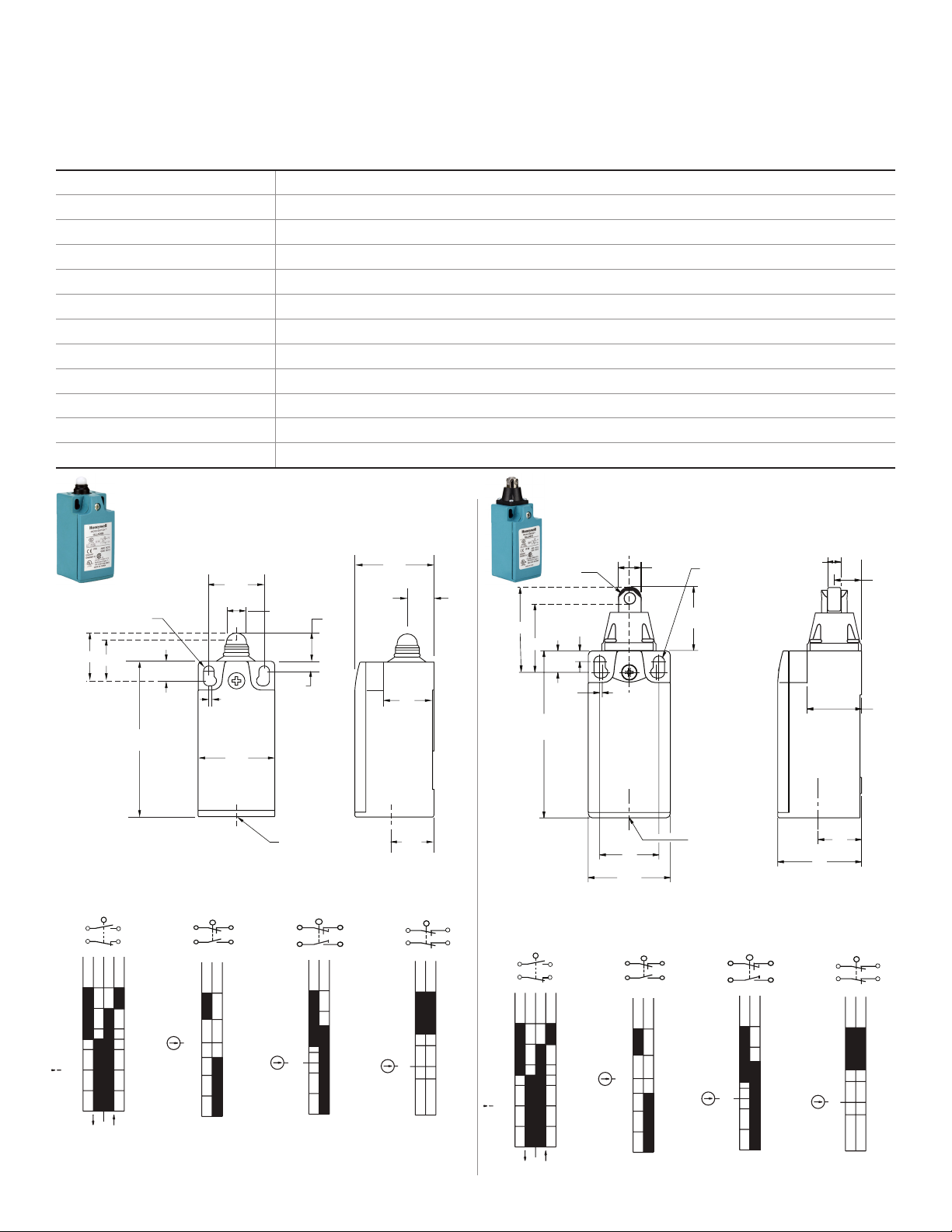
Circuitry 1 NO 1 NC direct opening snap action, slow action (BBM), slow action (MBB); 2NC slow action
Ampere rating 10 A (Thermal)
Supply voltage 300 Vac and 250 Vdc max.
Housing material Plastic
Termination type 12,7 mm [0.5 in] conduit; 20 mm [0.79 in] conduit
Housing type EN 50047
Shock 50 g per PEC 68227c (w/o actuator)
Vibration 10 g per IEC 6826 (w/o actuator)
Sealing IP66, NEMA 1, 12, 13
Approvals cULus, CE, CCC
Mechanical life 5 million operations
Operating temperature range 10 °C to 80 °C [14 °F to 176 °F]
Figure 1. GLLA**B, GLLC**B Dimensions and
Bar Charts
Snap Action
1NO/1NC
13 14
21 22
21-22
13-14
21-22
O
0
2 sensing.honeywell.com
13
28
55
70
O
O
O
O
(Break Before Make)
13-14
OF
12Ncm
1NO/1NC
11 12
23 24
23-24
11-12
O
0
O
OF
15
5Ncm
O
30
O
40
O
75
(Make Before Break)
15 16
23 24
1NO/1NC
O
0
O
20
O
35
O
45
O
75
23-24
15-16
OF
8Ncm
Slow Action
2NC
11
21
O
0
O
20
O
35
O
60
21-22
11-12
Figure 2. GLLA**C, GLLC**C Dimensions and
Bar Charts
OF
Page 3

GLL Series
Snap Action
Slow Action
(Break Before Make)
Slow Action
Slow Action
(Make Before Break)
1NO/1NC 1NO/1NC 1NO/1NC 2NC
2.5
4.5
6.5
0 mm
10 mm
11-12
23-24
OF
3N
2.5
8.0
0 mm
10 mm
5.5
21-22
13-14
21-22
13-14
OF
8 N
3.0
6.0
0 mm
10 mm
5.0
15-16
23-24
OF
5 N
3.5
5.5
0 mm
8 mm
11-12
21-22
OF
5 N
13 14
21 22
11 12
23 24
11 12
21 22
15 16
23 24
Snap Action
1NO/1NC
1,8
5,5
0 mm
8 mm
3,5
21-22
13-14
21-22
13-14
OF
8 N
13 14
21 22
Slow Action
(Break Before Make)
1NO/1NC
1,5
2,5
4
0 mm
8 mm
11-12
23-24
OF
3N
11 12
23 24
Slow Action
2NC
2,5
4
0 mm
6,5 mm
11-12
21-22
OF
5N
11 12
21 22
Slow Action
(Make Before Break)
1NO/1NC
2
4,5
0 mm
8 mm
3,5
15-16
23-24
OF
5 N
15 16
23 24
FP
OP
40,5
[1.59]
8
[0.31]
62
[2.44]
30,5
[1.20]
22
[0.87]
Conduit thread
31
[1.22]
16
[0.63]
105,5
[4.15]
1
[0.04]
22
[0.87]
15 [0.60]
5 [0.197]
24
[0.95]
21
[0.83]
18
[0.71]
10
[0.4]
[0.165]
Ø4,2
11,5 [0.45]
Ø 4,2
[0.165]
OP
4
[0.16]
8
[0.31]
62
[2.44]
30,5
[1.20]
22
[0.87]
Conduit thread
31
[1.22]
16
[0.63]
10
[0.39]
1
[0.04]
FP
31
[1.22]
ISSUE 5 50012101
Figure 3. GLLA**D, GLLC**D Dimensions and
Bar Charts
Figure 4. GLLA**F, GLLC**F Dimensions and
Bar Charts
Sensing and Internet of Things 3
Page 4

GLL Series
Snap Action
1NO/1NC
21-22
13-14
21-22
13-14
Slow Action
(Break Before Make)
1NO/1NC
11 12
23 24
Slow Action
(Make Before Break)
1NO/1NC
15-16
15 16
23 24
Slow Action
2NC
21-22
0
O
13
O
28
O
55
O
70
O
OF
12Ncm
11-12
23-24
0
O
15
O
30
O
40
O
75
O
OF
5Ncm
23-24
0
O
20
O
35
O
45
O
75
O
OF
8Ncm
11-12
0
O
20
O
60
O
35
O
OF
8Ncm
11 12
21 22
13 14
21 22
41 [1.57]
27
[1.06]
TT
OP
PT
DT
R 20 to 75
[0.79 to 2.95]
Plated
copper
alloy
19,5
[0.77]
4
[0.16]
Ø 17 x 7
[0.67 x 0.28]
8
[0.31]
62
[2.44]
30,5
[1.20]
22
[0.87]
Conduit thread
31
[1.22]
16
[0.63]
20
[0.79]
2
[0.08]
1
[0.04]
[0.165]
Ø4,2
Snap Action
1NO/1NC
21-22
13-14
21-22
13-14
Slow Action
(Break Before Make)
1NO/1NC
11 12
23 24
Slow Action
(Make Before Break)
1NO/1NC
15-16
15 16
23 24
Slow Action
2NC
21-22
0
O
13
O
28
O
55
O
70
O
OF
12Ncm
11-12
23-24
0
O
15
O
30
O
40
O
75
O
OF
5Ncm
23-24
0
O
20
O
35
O
45
O
75
O
OF
8Ncm
11-12
0
O
20
O
60
O
35
O
OF
8Ncm
11 12
21 22
13 14
21 22
[2.44]
[1.20]
[0.79]
ISSUE 5 50012101
Figure 5. GLLA**A1B, GLLC**A1B Dimensions
and Bar Charts
41 [1.57]
PT
OP
R 25
[0.98]
Ø4,2
[0.165]
19,5
[0.77]
Conduit thread
TT
Plated
copper
alloy
Ø 17 x 7
[0.67 x 0.28]
8
[0.31]
[0.04]
62
4
[0.16]
1
22
[0.87]
30,5
DT
27
[1.06]
31
[1.22]
16
[0.63]
Figure 6. GLLA**A2B, GLLC**A2B Dimensions
and Bar Charts
20
4 sensing.honeywell.com
Page 5

GLL Series
Snap Action
1NO/1NC
21-22
13-14
21-22
13-14
Slow Action
(Break Before Make)
1NO/1NC
11 12
23 24
Slow Action
(Make Before Break)
1NO/1NC
15-16
15 16
23 24
Slow Action
2NC
21-22
0
O
13
O
28
O
55
O
70
O
OF
12Ncm
11-12
23-24
0
O
15
O
30
O
40
O
75
O
OF
5Ncm
23-24
0
O
20
O
35
O
45
O
75
O
OF
8Ncm
11-12
0
O
20
O
60
O
35
O
OF
8Ncm
11 12
21 22
13 14
21 22
rubber
[1.20]
[0.79]
Snap Action
1NO/1NC
21-22
13-14
21-22
13-14
Slow Action
(Break Before Make)
1NO/1NC
11 12
23 24
Slow Action
(Make Before Break)
1NO/1NC
15-16
15 16
23 24
Slow Action
2NC
21-22
0
O
13
O
28
O
55
O
70
O
OF
12Ncm
11-12
23-24
0
O
15
O
30
O
40
O
75
O
OF
5Ncm
23-24
0
O
20
O
35
O
45
O
75
O
OF
8Ncm
11-12
0
O
20
O
60
O
35
O
OF
8Ncm
11 12
21 22
13 14
21 22
PT
TT
OP
DT
Ø 50
[1.96]
Buna
rubber
62
[2.44]
Conduit thread
30,5
[1.20]
8
[0.31]
1
[0.04]
19,5
[0.77]
4
[0.16]
20,65
[0.81]
42,5
[1.67]
10
[0.39]
2
[0.08]
20
[0.79]
16
[0.63]
31
[1.22]
[0.165]
Ø4,2
ISSUE 5 50012101
Figure 7. GLLA**A1Y, GLLC**A1Y Dimensions
and Bar Charts
Buna
Ø 50
[1.96]
62
[2.44]
[0.31]
8
[0.16]
[0.04]
PT
OP
DT
TT
Ø4,2
4
1
22
[0.87]
30,5
[0.165]
19,5
[0.77]
Conduit thread
42,5 [1.67]
10
[0.4]
[1.24]
31
[1.22]
31,5
16
[0.63]
Figure 8. GLLA**A2Y, GLLC**A2Y
Dimensions and Bar Charts
20
Sensing and Internet of Things 5
Page 6

GLL Series
Slow Action
Slow Action
55 [0.22]
20° - 65°
[0.57] - [5.91]
22 - 150
[0.77]
19,5
22
[0.87]
[1.20]
30,5
[2.44]
62
[0.32]
8
Conduit thread
[0.63]
16
[1.22]
31
[0.40]
10,2
[1.34]
34
[0.12]
0.3
[0.04]
1
[0.165]
Ø4,2
Figure 9. GLLA**A4J, GLLC**A4J Dimensions
and Bar Charts
ISSUE 5 50012101
13 14
21 22
0
13
28
55
70
Snap Action
1NO/1NC
21-22
13-14
21-22
O
O
O
O
O
(Break Before Make)
13-14
OF
12Ncm
1NO/1NC
11 12
23 24
23-24
11-12
O
0
O
OF
15
5Ncm
O
30
O
40
O
75
(Make Before Break)
1NO/1NC
15 16
23 24
23-24
15-16
O
0
O
20
O
35
O
45
O
75
OF
8Ncm
Slow Action
2NC
11 12
21 22
21-22
11-12
O
0
OF
O
20
8Ncm
O
35
O
60
6 sensing.honeywell.com
Page 7

GLL Series
ISSUE 5 50012101
Warranty/Remedy
Honeywell warrants goods of its manufacture as being free
of defective materials and faulty workmanship during the
applicable warranty period. Honeywell’s standard product
warranty applies unless agreed to otherwise by Honeywell
in writing; please refer to your order acknowledgment or
consult your local sales office for specific warranty details.
If warranted goods are returned to Honeywell during the
period of coverage, Honeywell will repair or replace, at its
option, without charge those items that Honeywell, in its sole
discretion, finds defective. The foregoing is buyer’s sole
remedy and is in lieu of all other warranties, expressed or
implied, including those of merchantability and fitness for a
particular purpose. In no event shall Honeywell be liable for
consequential, special, or indirect damages.
While Honeywell may provide application assistance personally,
through our literature and the Honeywell web site, it is buyer’s
sole responsibility to determine the suitability of the product in
the application.
Specifications may change without notice. The information we
supply is believed to be accurate and reliable as of this writing.
However, Honeywell assumes no responsibility for its use.
mWARNING
IF USED IN APPLICATIONS CONCERNING
HUMAN SAFETY
• Only use NC direct opening (“positive opening”/”positive
break”) contacts, identified by the symbol .
• Do NOT use flexible/adjustable actuators. Only use
actuators designed for safety applications.
• Do NOT defeat, tamper, remove, or bypass this switch.
• Hazardous voltage, disconnect power before servicing.
• Strictly adhere to all installation and maintenance
instructions.
• Consult with local safety agencies and their requirements
when designing a machine-control link, interface and all
control elements that affect safety.
Failure to comply with these instructions could result in
death or serious injury.
For more information
Honeywell Sensing and Internet of
Things services its customers through a
worldwide network of sales offices and
distributors. For application assistance,
current specifications, pricing or the
nearest Authorized Distributor, visit
sensing.honeywell.com or call:
Asia Pacific +65 63552828
Europe +44 1698 481481
USA/Canada +18005376945
Honeywell Sensing and Internet of Things
9680 Old Bailes Road
Fort Mill, SC 29707
honeywell.com
50012101 | 5 | 04/19
© 2019 Honeywell International Inc. All rights reserved.
 Loading...