

Page 1
Installation Instructions for the MICRO SWITCH™ GSX Global Explosion-Proof Safety Switch
Installationsanweisungen für den
explosionsgeschützten allgemeinen Sicherheitsschalter MICRO
SWITCH™ GSX
Istruzioni per l
Instructions d
Instruções de instalação para a
de
의
Instrucciones de instalación del
MICRO SWITCH™ GSX
全球防爆安全开关 MICRO SWITCH™ GSX
WARNING
death or serious injury.
Flame path
Max. gap
Comment
Push rod & bearing
0,076 mm
Cylindrical spigot joint
0518
II2GD
’installazione degli interruttori di sicurezza globali antideflagranti MICRO SWITCH™ GSX
’installation de l’interrupteur de sécurité antidéflagrant standard GSX MICRO SWITCH™
chave de segurança global MICRO SWITCH™ GSX à prova
explosão
설치 지침서
interruptor de seguridad global a prueba de explosiones
系列安装指南
GENERAL INFORMATION
Honeywell explosion-proof switches are designed
specifically for use in most hazardous location applications.
WARNING
IMPROPER INSTALLATION
• Consult with local safety agencies and their requirements
when designing a machine-control link, interface, and all
control elements that affect safety.
• Strictly adhere to all installation instructions
Failure to comply with these instructions could result in
death or serious injury.
WARNING
OPENING PRODUCTS HAZARD
DO NOT OPEN these products when energized or in a
flammable atmosphere.
Failure to comply with these instructions could result in
death or serious injury.
WARNING
IMPROPER CONDUIT THREAD USE
DO NOT USE any other conduit thread than the one identified
on the product. Verify that the mating threaded fitting is
identical with the conduit thread shown on the product
nameplate.
Failure to comply with these instructions could result in
death or serious injury.
RISK TO LIFE OR PROPERTY
Never use this product for an application involving serious
risk to life or property without ensuring that the system as a
whole has been designed to address the risks, and that this
product is properly rated and installed for the intended use
within the overall system.
Failure to comply with these instructions could result in
Refer to page 20 for mounting dimensions
Sensing and Productivity Solutions
The GSX enclosure is sealed for protection against
corrosion, water, dust and oil as defined in NEMA 1, 3, 4,
12, and 13 and IP67 (self certified by Honeywell). These
enclosures also meet the ATEX and IECEx designations:
Ex d IIC T6 ta -40 °C to +70 °C Gb and Ex t IIIC T85 °C Db
IP67.
GSX Series products also meet the Brazilian hazardous
locations designation:
Ex d IIC T6 Gb
Ex tb IIIC T85 °C Db
IP6X
-40 °C < Tamb < +70 °C
and comply with INMETRO requirements.
Compliance with Essential Health and Safety Requirements
has been assured by compliance with
ABNT NBR IEC 60079-0:2008
ABNT NBR IEC 60079-1:2009
ABNT NBR IEC 60079-31:2011
ABNT NBR IEC 60529:2009
Please refer to certificate number TÜV 14.0555 for
conditions of safe use.
Compliance with the Essential Health and Safety
Requirements has been assured by compliance with
EN60079-0:2006, EN 60079-1:2007, EN 61241-0:2006,
EN61241-1:2004, and IEC 60079-0:2007 Ed. 5, IEC 600791:2007 Ed. 6, and IEC 61241-1:2004.
The maximum contruction gap (ic) is less than that required
by Table 2 of EN/IEC 60079-1:2007, clause 5.2.2 as
detailed below.
GSX with conduit type 1/2-14NPT also meets the North
American Hazardous Locations Designation: NEMA 7 Class I, Groups B, C and D; NEMA 9 - Class II, Groups E, F
and G and comply with UL Standards UL 894 and UL 1203.
ISSUE 8
50032072
Page 2

MICRO SWITCH™ GSX Series
50032072
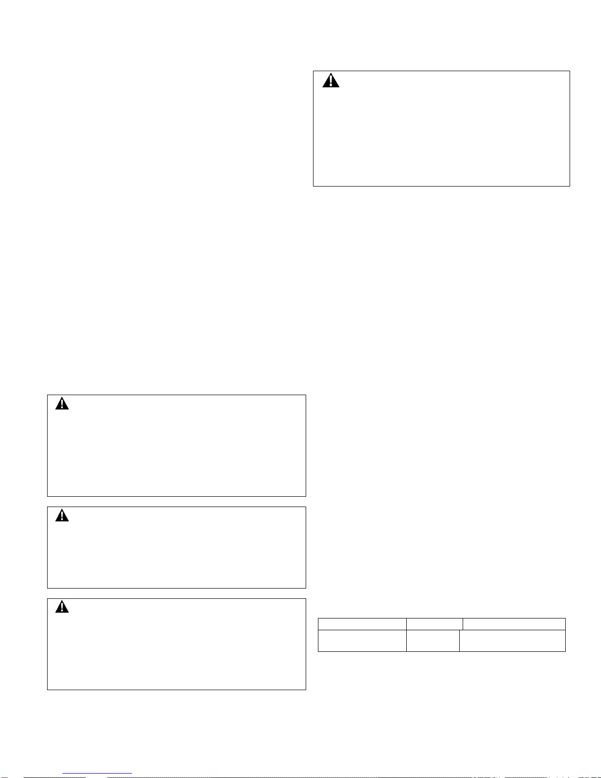
Figure 1.
Figure 2.
Figure 3. Changing
The GSX is often ideal for outdoor use or in adverse
environments where a combination of explosion proof plus
sealing requirements are needed. To comply with explosion
proof requirements the GSX has flame paths within the
housing, which cool exploding gases below the ignition
temperature before they reach explosive gases surrounding
the housing. Flame paths on the GSX are (1) an extended
plunger between the switch cavity and head and (2) the
cover-housing threads on the front of the switch.
All the basic switches used in the GSX Series incorporate a
positive break mechanism to force the NC (normally closed)
contacts open. This product complies with Machinery
Directive (89/392/EEC as amended by Directive
91/368/EEC) and complies with IEC/EN 60947-5-1.
MATERIALS OF CONSTRUCTION
The following materials are used in the GSX limit switch:
aluminum housing; buna-N seals; rubber, copper alloy, or
plastic rollers/plungers; zinc operating heads and actuator
arms. The suitability of these materials for the application
environment is solely up to the customer.
ADJUSTMENT, REPAIR, AND MAINTENANCE
The limit switch should be checked periodically by suitably
trained personnel for proper operation. Installation,
inspection, repair, and maintenance shall be carried out by
suitably trained personnel in accordance with the applicable
code of practice, e.g., EN/IEC 60079-14, EN/IEC 60079-19,
or EN/IEC 61241-14. The operating head may be rotated in
90° increments. Replacement operating heads or switching
elements may be ordered and installed. Repair beyond the
replacement of these components is not recommended.
REPLACING THE SWITCHING ELEMENT
Follow steps 2-13 in the installation instructions. The single
screw holding the switching element should be torqued to
0,56 Nm to 0,90 Nm [5 in-lb to 8 in-lb].
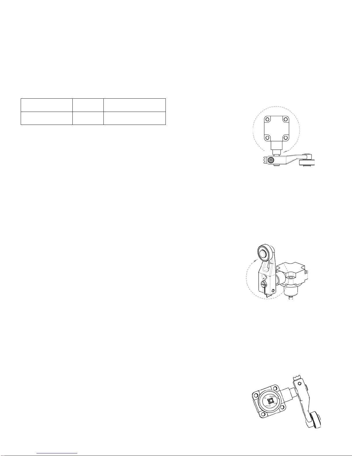
ROTATING OR REPLACING THE OPERATING HEAD
(SEE FIGURE 1)
1. Using the TORX
tamper-resistant
bit (included),
loosen tamperproof screws and
remove head.
2. Install the head in
the desired
position (90°
increments),
insuring seal
remains in correct
position while assembling head.
3. Torque tamper-proof screws 1,4 Nm to 1,8 Nm [12 in-lb
to 16 in-lb].
®
Rotating GSX Head
Issue 8
REVERSING THE ROLLER LEVER
Except for the offset roller levers, the roller arm may be
reversed to face the roller to the inside or outside of the arm.
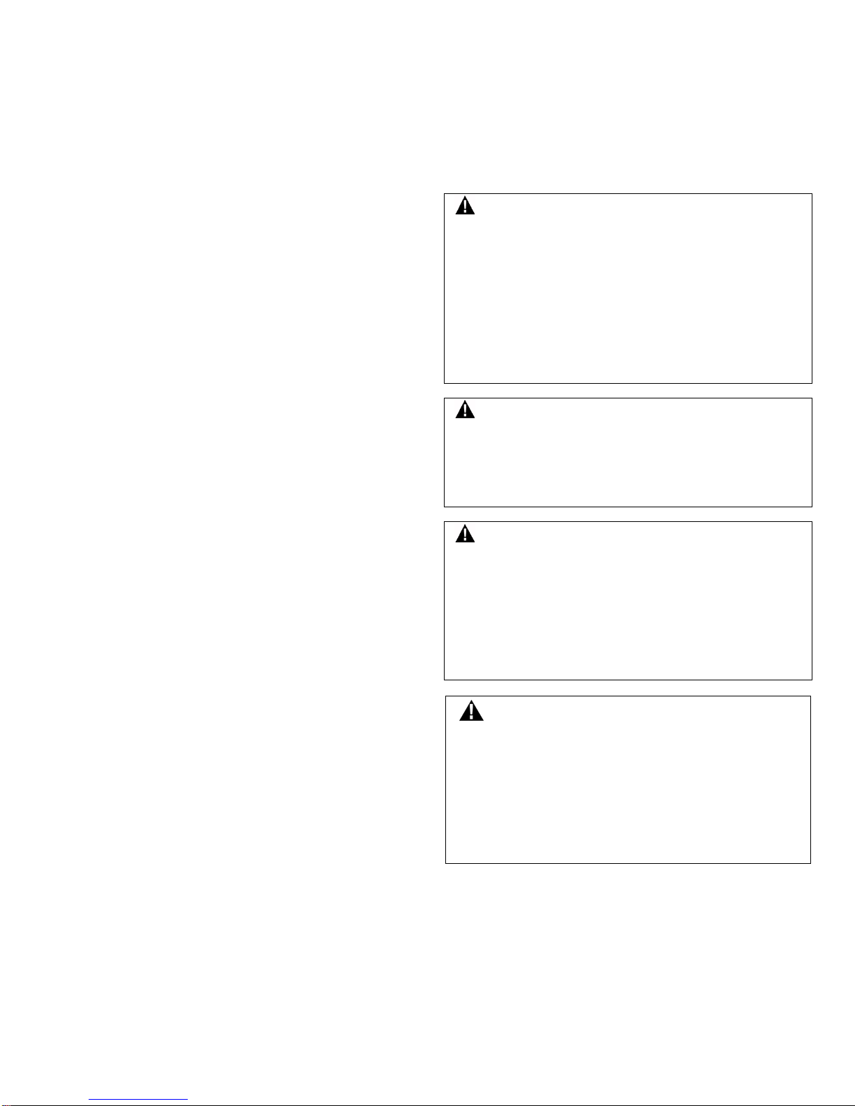
POSITIONING LEVER (SEE FIGURE 2)
The lever on rotaryactuated units is
adjustable to any
position through 360°
around the shaft.
1. Loosen the cap
screw with 9/64-inch
hexagon key wrench.
2. Move lever to
desired position
3. Securely tighten
screw until teller tab
can no longer be
moved by hand.
4. Tighten screw another 1/8 to 1/4 turn to assure lever is
tight on the shaft.
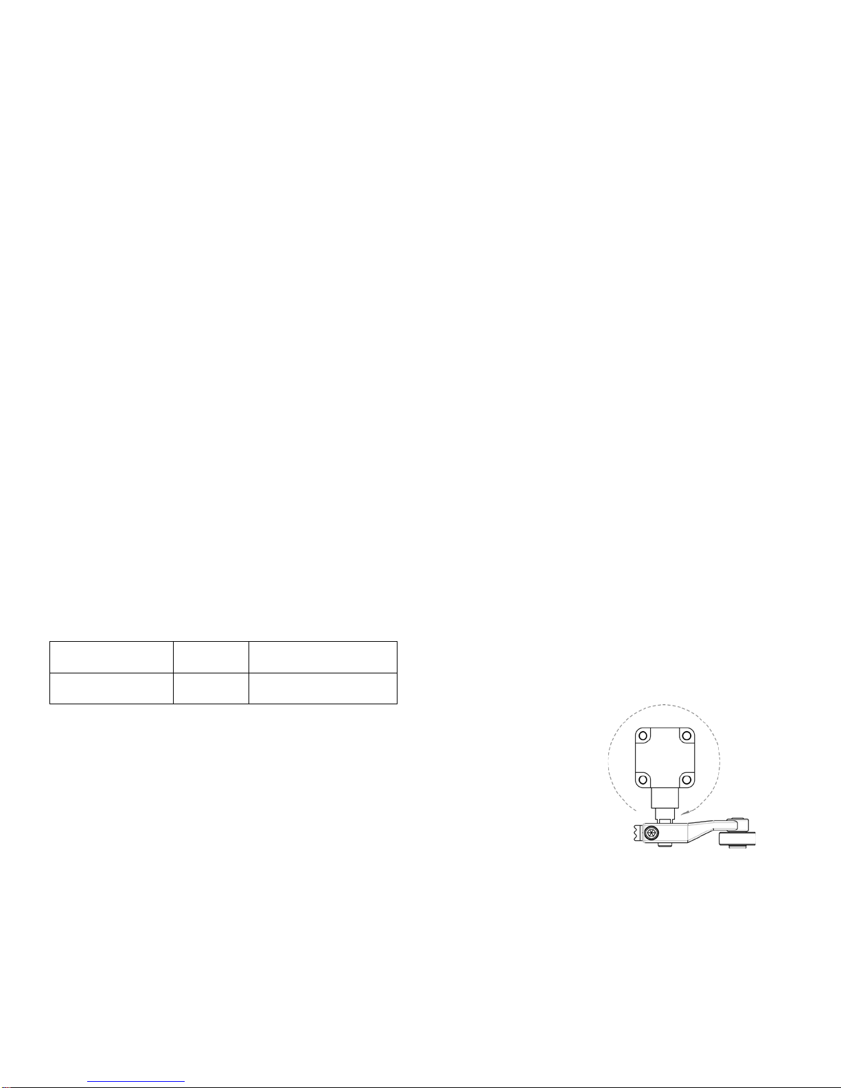
CHANGING DIRECTION OF ACTUATION OF SIDE
ROTARY HEAD
(SEE FIGURE 3)
The side rotary head
can be adjusted to only
rotate clockwise,
counterclockwise, or
both.
1. Loosen the four
captive head screws
to remove the head.
2. Lift the plastic
plunger and rotate it
so the key lines up
with the desired direction of rotation.
3. Replace the head and securely tighten the four screws
to 1,4 Nm to 1,8 Nm [12 in-lb to 16 in-lb].
INSTALLATION INSTRUCTIONS
1. Mount switch using M5 or #10 screws. Torque screws
to 4,9 Nm to 5,9 Nm [43 in-lb to 52 in-lb].
2. Refer to circuit diagram on switch housing. Diagram
depicts safety switch with actuator at free position.
3. Unscrew cover to expose the switching element for
wiring or replacement. To aid in cover removal, a
screwdriver or bar may be used on the wrenching lugs.
4. Connect stranded wire (0,75 mm
AWG) or solid wire (0,75 mm
to connector terminals. Stripped wire ends or any
spade and ring connector that will fit the terminals may
be used. Spades may be up to 7,9 mm [0.312 in] wide,
rings up to 7,9 mm [0.312 in] diameter. With spade or
ring type connections, pre-insulated connectors or
heat-shrinkable tubing should be used to provide
insulation between terminals.
Positioning GSX lever
actuation of GSX
side rotary head
2
to 2,5 mm2, 18-14
2
to 1,5 mm2, 18-16 AWG)
2 sensing.honeywell.com
Page 3
MICRO SWITCH™ GSX Series
50032072
WARNUNG
GEFAHR FÜR LEBEN ODER EIGENTUM
schweren Verletzungen und zum Tod führen.
Flammenpfad
Max. Fuge
Anmerkung
Schubstange
und Lager
0,076 mm
Zylindrischer
Zapfenanschluss
5. Wire the double pole units by connecting lead wires
to the terminals nearest the conduit opening first. An
internal grounding screw is located on the right side;
an external grounding screw is located on the upper
left side. Torque all M3 terminal screws and grounding
screws to 1-1,8 Nm [9-16 in-lb]. Use Class I and Class
II Division I wiring method in accordance with the
National Electric Code (NEC) NFPA 70.
6. Seal conduit opening with listed conduit sealing
fitting suitable for Class I Groups B, C, and D; Class II
Groups E, F, and G, and according to instructions in
PK 80112. Conduit size is listed on switch nameplate.
7. Reassemble cover and torque to 10 Nm [90 in-lb].
8. Put cover locking clamp on circular cover and tighten
the Torx screw to 1,4 Nm to 1,8 Nm [12 in-lb to 16 in-lb]
using the included Torx tamper resistant bit.
9. Perform functional tests.
10. Actuate the limit switch several times to ensure smooth
actuation
11. Ensure the normally closed contacts open when
protective guard is open
12. Confirm appropriate travel in order to ensure positive
break of the normally closed contacts according to
Figures 8-10.
13. The internal grounding terminal must be used for
the equipment grounding connection and the external
terminal is for supplementary bonding connection
where local codes or authorities permit or require
such connections.
WARNUNG
FEHLERHAFTE INSTALLATION
• Beachten Sie die Anforderungen der regional für die
Sicherheit zuständigen Institutionen in Bezug auf
Maschinensteuerung, Bedienerschnittstelle und alle
sicherheitsrelevanten Bedienelemente.
• Halten Sie sich strikt an die Installationsanleitung.
Die Missachtung dieses Sicherheitshinweises kann zu
schweren Verletzungen und zum Tod führen.
WARNUNG
GEFAHR BEIM ÖFFNEN VON PRODUKTEN
ÖFFNEN SIE DIESE PRODUKTE NICHT, während Energie
zugeführt wird oder sie sich in einer Atmosphäre mit
entflammbaren befinden.
Die Missachtung dieses Sicherheitshinweises kann zu
schweren Verletzungen und zum Tod führen.
WARNUNG
FALSCHE LEITUNGSZUFÜHRUNG
VERWENDEN SIE AUSSCHLIESSLICH die auf dem Produkt
angegebene Leitungszuführung mit passendem Gewinde.
Stellen Sie sicher, dass das Gegenstück mit einem
entsprechenden Gewinde (siehe Typenschild) ausgestattet ist.
Die Missachtung dieses Sicherheitshinweises kann zu
schweren Verletzungen und zum Tod führen.
Issue 8
Verwenden Sie dieses Produkt niemals für eine Anwendung,
wenn dies eine ernsthafte Gefahr für Leben oder Eigentum
darstellt, ohne sich zu versichern, dass das System als
Ganzes für solche Risiken ausgelegt wurde und dieses
Produkt für einen solchen Gebrauch innerhalb des gesamten
Systems richtig bewertet und installiert wurde.
Die Missachtung dieses Sicherheitshinweises kann zu
Montagemaße siehe Seite 20
ALLGEMEINE INFORMATIONEN
Explosionssichere Schalter von Honeywell wurden für
den Einsatz auch in den gefährlichsten Umgebungen
entwickelt. Das GSX-Gehäuse ist versiegelt, um vor
Korrosion, Wasser, Schmutz und Öl nach Maßgabe von
NEMA 1, 3, 4, 12 und 13 sowie IP67 zu schützen (selbst
zertifiziert von Honeywell). Dieses Gehäuse entspricht
zudem den ATEX- und IECEx-Festlegungen:Ex d IIC T6
ta -40 °C bis +70 °C Gb und Ex t IIIC T85 °C Db IP67.
Die Produkte der GSX-Serie erfüllen auch die
Anforderungen der brasilianischen Schutzarten für
Gefahrenbereiche:
Ex d IIC T6 Gb
Ex tb IIIC T85 °C Db
IP6X
-40 °C < Tamb < +70 °C
sowie die Anforderungen gemäß INMETRO.
Die Übereinstimmung mit den einschlägigen Gesundheitsund Sicherheitsanforderungen ist durch Übereinstimmung
mit den folgenden Normen gegeben:
ABNT NBR IEC 60079-0:2008
ABNT NBR IEC 60079-1:2009
ABNT NBR IEC 60079-31:2011
ABNT NBR IEC 60529:2009
Hinweise zu sicheren Betriebsbedingungen entnehmen Sie
dem TÜV-Zertifikat 14.0555.
Die Einhaltung der allgemeinen Gesundheits- und
Sicherheitsanforderungen wird durch Erfüllung der Normen
EN 60079-0:2006, EN 60079-1:2007, EN 61241-0:2006,
EN 61241-1:2004 und IEC 60079-0:2007 Ed.5, IEC 600791:2007 Ed.6 sowie IEC 61241-1:2004 erreicht.
Die maximal erlaubte Fuge (ic) ist kleiner als in Tabelle 2
von EN/IEC 60079-1:2007, Klausel 5.2.2 (siehe unten).
GSX-Schalter mit Leitungstyp 1/2-14NPT entsprechen
den nordamerikanischen Anforderungen für gefährliche
Umgebungen:NEMA 7 – Klasse I, Gruppen B, C und D,
NEMA 9 – Klasse II, Gruppen E, F und G sowie ULStandards UL 894 und UL 1203.
Honeywell Sensing and Productivity Solutions 3
Page 4
MICRO SWITCH™ GSX Series
Issue 8 50032072
Abbildung 1:
Abbildung 2:
Abbildung 3:
GSX-Schalter sind für den Außeneinsatz sowie den Einsatz
in Umgebungen mit gefährlicher Atmosphäre geeignet, in
denen Explosionssicherheit und Versiegelung erforderlich
sind. Um die Anforderungen an die Explosionssicherheit
zu erfüllen, wurde der GSX im Gehäuseinneren mit
Flammenpfaden ausgestattet, die explodierende Gase
unter den Zündpunkt abkühlen, bevor sie in die das
Gehäuse umgebende Atmosphäre entlassen werden.
Die Flammenpfade im GSX bestehen aus (1) einem
verlängerten Plunger zwischen Schalterinnenraum und kopf sowie (2) den Gewinden der Gehäuseabdeckung
auf der Vorderseite des Schalters.
Alle in der Serie GSX eingesetzten Schalter besitzen
einen Positivunterbrecher, der die Ruhekontakte (NC =
Normally Closed) offen hält. Dieses Produkt erfüllt die
Maschinenrichtlinie (89/392/EWG in der Fassung der
Richtlinie 91/368/EWG) sowie IEC/EN 60947-5-1.
KONSTRUKTIONSMATERIALIEN
Im GSX-Grenzwertschalter wurden die folgenden Materialien
verbaut:Aluminiumgehäuse, Buna N-Dichtungen, Walzen/
Plunger aus Gummi, Kupferlegierung oder Kunststoff,
Betriebsköpfe und Aktuatorarme aus Zink. Die Eignung
dieser Materialien für die vorgesehene Umgebung ist
vom Kunden sicherzustellen.
EINSTELLUNG, REPARATUR UND WARTUNG
Der Grenzwertschalter muss regelmäßig von geschultem
Personal auf fehlerfreien Betrieb überprüft werden.
Installation, Inspektion, Reparatur und Wartung müssen
von entsprechend geschultem Personal nach Maßgabe der
geltenden Richtlinien (EN/IEC 60079-14, EN/IEC 60079-19
oder EN/IEC 61241-14) vorgenommen werden. Der
Betriebskopf kann in 90°-Schritten gedreht werden.
Betriebsköpfe und Schaltkomponenten können als
Ersatzteile bestellt und ausgetauscht werden. Von anderen
Reparaturen als dem Austausch dieser Komponenten wird
abgeraten.
AUSTAUSCHEN DES SCHALTELEMENTS
Führen Sie die Schritte 2–13 der Installationsanleitung
durch. Die einzelne Schraube, die das Schaltelement fixiert,
ist mit 0,56 Nm bis 0,90 Nm anzuziehen.
DREHEN ODER AUSTAUSCHEN DES BETRIEBSKOPFS
(SIEHE ABBILDUNG 1)
1. Verwenden Sie
das mitgelieferte
®
-Bit, lösen Sie die
TORX
eingriffssicheren Schrauben,
und entfernen Sie den Kopf.
2. Installieren Sie den Kopf in
der gewünschten Position
(90°-Schritte). Stellen Sie
beim Einbau des Kopfs
sicher, dass sich die
Dichtung an der richtigen
Position befindet.
GSX-Drehkopf
3. Ziehen Sie die eingriffssicheren Schrauben mit 1,4 Nm
bis 1,8 Nm fest.
UMDREHEN DES HEBELARMS
Außer bei Offset-Hebelarmen kann der Arm umgedreht
werden, die Walze also auf der Außen- oder der Innenseite
positioniert werden.
HEBEL POSITIONIEREN (SIEHE ABBILDUNG 2)
Der Hebel der Dreheinheiten kann an jeder beliebigen
Position (360°) auf der Achse fixiert werden.
1. Lösen Sie die
Kopfschraube mit
einem 9/64-ZollInbusschlüssel.
2. Bewegen Sie
den Hebel an
die gewünschte
Position.
3. Ziehen Sie die
Schraube fest,
bis sich der
Positionsreiter nicht mehr von Hand bewegen lässt.
4. Drehen Sie die Schraube dann um eine weitere 1/8–1/4
Umdrehung, um sicherzustellen, dass der Hebel fest
auf der Achse sitzt.
BEWEGUNGSRICHTUNG DES SEITLICHEN
DREHKOPFS ÄNDERN (SIEHE ABBILDUNG 3)
Der seitliche Drehkopf kann für die Drehung im oder gegen
den Uhrzeigersinn bzw.
in beiden Richtungen
konfiguriert werden.
1. Lösen Sie
die vier
unverlierbaren
Schrauben,
um den Kopf
auszubauen.
2. Heben Sie den
Kunststoffplung
er, an und
drehen Sie ihn
auf die gewünschte Bewegungsrichtung.
3. Setzen Sie den Kopf wieder auf, und ziehen Sie
die vier Schrauben mit 1,4 Nm bis 1,8 Nm fest.
INSTALLATIONSANLEITUNG
1. Montieren Sie den Schalter mit M5- oder #10-
Schrauben. Ziehen Sie die Schrauben mit 4,9 Nm bis
5,9 Nm fest.
2. Beachten Sie das Schaltbild auf dem Schaltergehäuse.
Das Diagramm zeigt den Sicherheitsschalter mit
unverriegeltem Aktuator.
3. Lösen Sie die Schrauben der Abdeckung, um an das
Schaltelement zu gelangen und es zu verdrahten oder
auszutauschen. Zum Lösen der Abdeckung kann z. B.
ein Schraubendreher oder Stab unter die Gewindenasen
geschoben werden.
GSX-Hebelarm positionieren
Bewegungsrichtung
des seitlich angebrachten
GSX-Drehkopfs ändern
4 sensing.honeywell.com
Page 5
MICRO SWITCH™ GSX Series
AVVERTENZA
RISCHI PER LA VITA O PER LA PROPRIETÀ
o gravi lesioni personali.
4. Schließen Sie Litze (0,75 mm2 bis 2,5 mm2, 18-14
AWG) bzw. Draht (0,75 mm
an die Anschlussklemmen an. Für die Anschlussklemmen
können abisolierte Kabelenden, aber auch alle
passenden Kabelschuhe und -stecker verwendet
werden. Kabelschuhe dürfen bis zu 7,9 mm breit sein,
Stecker einen Durchmesser bis 7,9 mm aufweisen.
Bei Anschlüssen per Kabelschuh oder -stecker müssen
isolierte Verbinder oder Schrumpfschläuche verwendet
werden, damit die Anschlussklemmen voneinander
isoliert sind.
5. Verdrahten Sie die zweipoligen Einheiten, indem Sie
Zuleitungsdrähte an die Anschlussklemmen unmittelbar
neben der Leitungszuführung anschließen. Eine interne
Erdungsschraube befindet sich auf der rechten Seite,
oben links befindet sich die externe Erdungsschraube.
Ziehen Sie alle M3-Terminalschrauben und
Erdungsschrauben mit 1–1,8 Nm fest.
gemäß National Electric Code (NEC) NFPA 70,
Klasse I und Klasse II, Abschnitt I.
6. Versiegeln Sie die
Leitungsdurchführung gemäß den
Anweisungen in PK 80112 mit geeigneter Dichtung
versiegeln (Klasse I, Gruppen B, C und D; Klasse II,
Gruppen E, F und G). Die Größe des Leitungsrohrs
ist auf dem Typenschild angegeben.
7. Bringen Sie die Abdeckung wieder an (mit 10 Nm).
8. Setzen Sie die Deckelverschlussklemme auf den
runden Deckel, und befestigen Sie unter Zuhilfenahme
des mitgelieferten verfälschungssicheren Torx-Bits die
Torx-Schraube mit 1,4 bis 1,8 Nm
9. Führen Sie Funktionstests durch.
10. Lösen Sie den Grenzwertschalter mehrmals aus, um zu
überprüfen, ob die Aktuation problemlos möglich ist.
11. Prüfen Sie, ob die Ruhekontakte (NC) sich öffnen,
wenn die Schutzvorrichtung geöffnet wird.
12. Prüfen Sie auf ungehinderte Bewegung, um die
Positivunterbrechung der Ruhekontakte (NC) nach
Maßgabe der Abbildungen 8–10 sicherzustellen.
13. Die interne Erdungsklemme muss für die Erdung der
Anlage angeschlossen werden. Die externe Klemme
soll hingegen für eine zusätzliche Masseverbindung
verwendet werden wo örtliche Vorschriften oder
Behörden dies gestatten oder gar vorschreiben.
2
bis 1,5 mm2, 18-16 AWG)
AVVERTENZA
INSTALLAZIONE ERRATA
• Rivolgersi alle agenzie per la sicurezza locali e consultarne i
requisiti quando si progetta un collegamento o un’interfaccia
di controllo macchina e tutti gli elementi di controllo che
influiscono sulla sicurezza.
• Rispettare scrupolosamente le istruzioni di installazione.
Il mancato rispetto di tali istruzioni può causare morte
o gravi lesioni personali.
Verkabelung
Issue 8 50032072
AVVERTENZA
APERTURA DEI PRODOTTI
NON APRIRE questi prodotti se in tensione o in presenza
di infiammabili.
Il mancato rispetto di tali istruzioni può causare morte
o gravi lesioni personali.
AVVERTENZA
USO DI FILETTATURE PRESSACAVO NON IDONEE
NON UTILIZZARE filettature pressacavo diverse da quelle
indicate sul prodotto. Assicurarsi che il raccordo filettato
per l’accoppiamento sia identico alla filettatura pressacavo
mostrata sulla targhetta del prodotto.
Il mancato rispetto di tali istruzioni può causare morte
o gravi lesioni personali.
Non utilizzare questo prodotto per nessuna applicazione
che comporti serie conseguenze per la vita o per la proprietà,
senza aver prima accertato che l’intero sistema sia a prova di
rischio e che questo prodotto sia stato valutato adeguatamente
e che sia stato installato per l’uso previsto all’interno dello
stesso sistema.
Il mancato rispetto di tali istruzioni può causare morte
Fare riferimento alla pagina 20 per le dimensioni di montaggio
INFORMAZIONI GENERALI
Gli interruttori a prova di esplosione di Honeywell sono
progettati specificamente per l’uso nelle applicazioni più
pericolose. L’alloggiamento GSX è sigillato per garantire
la protezione contro corrosione, acqua, polvere e grasso,
secondo quanto definito nelle direttive NEMA 1, 3, 4,
12 e 13 e IP67 (auto certificate da Honeywell). Questi
alloggiamenti sono conformi anche alle specifiche ATEX
e IECEx: Ex d IIC T6 ta da -40 °C a +70 °C Gb ed Ex t IIIC
T85 °C Db IP67.
I prodotti GSX Series soddisfano anche la designazione
di ambienti pericolosi brasiliana:
Ex d IIC T6 Gb
Ex tb IIIC T85 °C Db
IP6X
-40 °C < Tamb < +70 °C
e sono conformi con i requisiti INMETRO.
La conformità con i requisiti essenziali relativi a salute
e sicurezza è garantita dalla conformità con
ABNT NBR IEC 60079-0:2008
ABNT NBR IEC 60079-1:2009
ABNT NBR IEC 60079-31:2011
ABNT NBR IEC 60529:2009
Per le condizioni di utilizzo sicuro, fare riferimento al
numero di certificato TÜV 14.0555.
Honeywell Sensing and Productivity Solutions 5
Page 6
MICRO SWITCH™ GSX Series
Issue 8 50032072
Figura 2.
Percorso della
fiamma
Gap
massimo
Commento
Push rod e
cuscinetto
0,076 mm
Giunto a bicchiere
cilindrico
Figura 1.
Figura 3. Modifica
Il rispetto delle prescrizioni minime di salute e sicurezza è
assicurato dalla conformità alle direttive EN 60079-0:2006,
EN 60079-1:2007, EN 61241-0:2006, EN 61241-1:2004 e
IEC 60079-0:2007 Ed. 5, IEC 60079-1:2007 Ed. 6 e IEC
61241-1:2004.
Il gap massimo di costruzione è inferiore a quello richiesto
nella Tabella 2 della direttiva EN/IEC 60079-1:2007,
clausola 5.2.2, come descritto di seguito.
L’interruttore GSX con tipo di condotto 1/2-14NPT è
conforme anche alla North American Hazardous Locations
Designation: NEMA 7 - Classe I, Gruppi B, C e D; NEMA 9
- Classe II, Gruppi E, F e G. È inoltre conforme agli
standard UL 894 e 1203.
L’interruttore GSX è ideale per gli usi esterni o in condizioni
ambientali difficili, in cui sono necessari dispositivi a prova
di esplosione e sigillati. Per garantire la conformità ai requisiti
antiesplosione, l’interruttore GSX include nell’alloggiamento
percorsi della fiamma che portano i gas esplosivi al di sotto
della temperatura di accensione prima che raggiungano
i gas esplosivi che circondano l’alloggiamento. I percorsi
della fiamma (1) un tuffante esteso tra la cavità e la testa
dell’interruttore sono e (2) le filettature dell’alloggiamento
sulla parte anteriore.
Tutti gli interruttori di base della serie GSX includono un
meccanismo di distacco obbligato per forzare l’apertura dei
contatti NC (Normally Closed). Questo prodotto è conforme
alla Direttiva macchine (89/392/CEE, emendata dalla
Direttiva 91/368/CEE) e agli standard IEC/EN 60947-5-1.
MATERIALI PER LA COSTRUZIONE
Per la realizzazione dell’interruttore di fine corsa GSX
vengono utilizzati i seguenti materiali: alloggiamento in
alluminio, guarnizioni in Buna N, rulli e stantuffi in gomma,
lega di rame o plastica, braccetti dell’attuatore e teste
operatrici in zinco. È esclusiva responsabilità del cliente
valutare se questi materiali sono adatti all’ambiente
operativo.
REGOLAZIONE, RIPARAZIONE E MANUTENZIONE
Il corretto funzionamento dell’interruttore di fine corsa deve
essere verificato periodicamente da personale qualificato.
Le operazioni di installazione, ispezione, riparazione e
manutenzione devono essere eseguite da personale
qualificato conformemente al codice di condotta applicabile,
ossia EN/IEC 60079-14, EN/IEC 60079-19 o EN/IEC
61241-14. La testa operativa deve essere ruotata con
incrementi di 90°. È possibile ordinare e installare teste
operative o elementi di commutazione di ricambio. Si
sconsiglia di eseguire ulteriori interventi di riparazione.
SOSTITUZIONE DELL’ELEMENTO DI COMMUTAZIONE
Seguire i passaggi da 2 a 13 delle istruzioni di installazione. Il
momento torcente della singola vite che trattiene l’elemento di
commutazione deve essere compreso tra 0,56 Nm e 0,90 Nm.
ROTAZIONE O SOSTITUZIONE DELLA TESTA
OPERATIVA (VEDERE LA FIGURA 1)
1. Utilizzando il bit TORX
antimanomissione
(incluso), allentare le
viti e rimuovere la testa.
2. Installare la testa nella
posizione desiderata
(con incrementi di 90°),
assicurandosi che la
guarnizione resti nella
posizione corretta.
3. Serrare le viti
antimanomissione
applicando una forza
compresa tra 1,4 Nm
e 1,8 Nm.
INVERSIONE DELLA LEVA CON RULLO
Ad eccezione delle leve con rullo non allineate, il braccetto
con rullo può essere invertito in modo da rivolgere il rullo
verso la parte interna o esterna del braccetto.
POSIZIONAMENTO DELLA LEVA (VEDERE LA FIGURA 2)
La leva sulle unità ad
attuazione rotatoria è
regolabile su qualsiasi
posizione con una
rotazione di 360°
intorno all’asse.
1. Allentare la vite
mordente con una
chiave esagonale
per brugole da
9/64".
2. Spostare la leva
nella posizione desiderata.
3. Serrare la vite facendo in modo che la linguetta di
indicazione non possa essere più spostata manualmente.
4. Fare ancora 1/8 o 1/4 di giro per assicurarsi che la leva
sia ben fissata all’asse.
MODIFICA DELLA DIREZIONE DI ATTUAZIONE DELLA
TESTINA ROTANTE LATERALE (VEDERE LA FIGURA 3)
È possibile regolare la
testina rotante laterale
in modo che ruoti solo in
senso orario, solo in senso
antiorario o in entrambi
i sensi.
1. Allentare le quattro
viti prigioniere per
rimuovere la testina.
®
Rotazione della testa GSX
Posizionamento della leva GSX
dell’attuazione della
testina rotante laterale GSX
6 sensing.honeywell.com
Page 7
MICRO SWITCH™ GSX Series
Issue 8 50032072
AVERTISSEMENT
RISQUE POUR LA VIE ET LA PROPRIÉTÉ
sérieuses lésions, et même la mort.
2. Sollevare il tuffante di plastica e ruotarlo, in modo
da allineare la chiave alla posizione di rotazione
desiderata.
3. Sostituire la testina e serrare saldamente le quattro viti
applicando una forza compresa tra 1,4 Nm e 1,8 Nm.
ISTRUZIONI DI INSTALLAZIONE
1. Installare l’interruttore utilizzando viti M5 o n. 10.
Serrare le viti applicando una forza compresa tra
4,9 Nm e 5,9 Nm.
2. Fare riferimento al diagramma del circuito sulla custodia
dell’interruttore. Il diagramma raffigura l’interruttore di
sicurezza con l’attuatore in posizione libera.
3. Svitare la copertura per accedere all’elemento di
commutazione per la verifica del cablaggio o per
le sostituzioni. Per semplificare la rimozione della
copertura, è possibile utilizzare un cacciavite o
una barra sulle alette di manovra.
4. Collegare il cavo a conduttori multipli (da 0,75 mm
a 2,5 mm
(da 0,75 mm
connettore. È possibile utilizzare le estremità del filo
spelato o qualsiasi connettore a paletta o anulare
adatto ai terminali. Le palette possono avere una
larghezza massima di 7,9 mm, gli anelli un diametro
massimo di 7,9 mm. Con le connessioni a paletta o
anulari, è necessario utilizzare connettori preisolati
o una guaina termoretrattile per fornire l’isolamento
tra i terminali.
5. Cablare le unità bipolari connettendo i conduttori prima
ai terminali più vicini all’apertura del condotto. Sul lato
destro è presente una vite di collegamento a massa
interna; sul lato superiore sinistro è presente una vite
di collegamento a massa esterna. Serrare tutte le viti
terminali M3 e le viti di collegamento a massa con una
forza di 1-1,8 Nm. Utilizzare il metodo di cablaggio
Classe I e Classe II Divisione I in conformità allo
standard NEC (National Electric Code) NFPA 70.
6. Sigillare l’apertura del condotto con il materiale
sigillante adatto al condotto indicato per la Classe I
Gruppi B, C e D e per la Classe II Gruppi E, F e G, e
seguendo le istruzioni fornite nel documento PK 80112.
Le dimensioni del condotto sono riportate sulla
targhetta dell’interruttore.
7. Riassemblare la copertura e serrare con una forza
di 10 Nm.
8. Montare il morsetto di bloccaggio sul coperchio
circolare e serrare le viti Torx applicando una forza
compresa tra 1,4 Nm e 1,8 Nm utilizzando il bit
antimanomissione Torx in dotazione.
9. Eseguire verifiche funzionali.
10. Azionare l’interruttore di fine corsa più volte per
verificare che l’attuazione sia agevole.
11. Assicurarsi che i contatti NC si aprano quando lo
schermo protettivo è aperto.
12. Verificare che la corsa sia appropriata per garantire il
distacco obbligato dei contatti NC, come illustrato nelle
Figure 8-10.
2
, 18-14 AWG) o il filo con conduttori solidi
2
a 1,5 mm2, 18-16 AWG) ai terminali del
13. Il morsetto di terra interno deve essere usato per il
collegamento di messa a terra dell’attrezzatura mentre
il morsetto di terra esterno deve essere usato per
collegamenti supplementari in casi in cui sia permesso
o sia richiesto da normative o enti locali.
AVERTISSEMENT
INSTALLATION INCORRECTE
• Consultez les autorités de sécurité locales et leurs
spécifications lors de la conception d’une liaison de
commande de machine, d’une interface, et de tous
les éléments de commande pouvant affecter la
sécurité.
• Conformez-vous strictement aux instructions
d’installation
Le non-respect de ces instructions peut entraîner
2
de sérieuses lésions et même la mort.
AVERTISSEMENT
RISQUE D’OUVERTURE DES PRODUITS
NE PAS OUVRIR ces produits lorsqu’ils sont sous
tension ou en présence d’un inflammable.
Le non-respect de ces instructions peut entraîner
de sérieuses lésions et même la mort.
AVERTISSEMENT
UTILISATION INADEQUATE D’UN FILETAGE DE
CONDUIT
NE PAS UTILISER de filetage de conduit autre que
celui identifié sur le produit. Vérifier que le raccord fileté
d’accouplement est identique au filetage de conduit
présenté sur la plaque signalétique du produit.
Le non-respect de ces instructions peut entraîner
de sérieuses lésions et même la mort.
N’utilisez jamais ce produit pour une application posant un
risque important pour la vie ou la propriété sans vous être
d’abord assuré que le système dans son ensemble a été
conçu pour éviter ce risque, que le produit possède la cote
appropriée et que celui-ci a été installé en fonction de
l’utilisation prévue.
Le non-respect de ces instructions peut entraîner de
Reportez-vous à la page 20 pour obtenir les dimensions
de montage.
Honeywell Sensing and Productivity Solutions 7
Page 8
MICRO SWITCH™ GSX Series
Issue 8 50032072
Arrête-flammes
Écart
maximum
Commentaire
Barre de liaison
et pallier
0,076 mm
Joint à emboîtement
cylindrique
Figure 1.
INFORMATIONS GENERALES
Les interrupteurs antidéflagrants Honeywell sont
spécifiquement conçus pour une utilisation avec la plupart
des applications de site à risque. Le boîtier GSX est scellé
pour une protection contre la corrosion, l’eau, la poussière
et l’huile telle que définie dans NEMA 1, 3, 4, 12, et 13 et
IP67. Ces boîtiers répondent également aux désignations
ATEX et IECEx : Ex d IIC T6 ta -40 °C à +70 °C Gb et Ex t
IIIC T85 °C Db IP67.
Les produits GSX Series sont également conformes aux
normes brésiliennes sur les zones dangereuses :
Ex d IIC T6 Gb
Ex tb IIIC T85 °C Db
IP6X
-40 °C < Temp. ambiante < +70 °C
Ils respectent les exigences définies par INMETRO.
La conformité aux principales exigences en matière d’hygiène
et de sécurité est garantie par le respect des normes
ABNT NBR CEI 60079-0:2008
ABNT NBR CEI 60079-1:2009
ABNT NBR CEI 60079-31:2011
ABNT NBR CEI 60529:2009
Pour connaître les conditions préalables à une utilisation sans
danger, reportez-vous au numéro de certificat TÜV 14.0555.
La conformité aux exigences sanitaires et de sécurité a
été assurée selon les spécifications EN 60079-0:2006,
EN 60079-1:2007, EN 61241-0:2006, EN 61241-1:2004
et IEC 60079-0:2007 Ed. 5, IEC 60079-1:2007 Ed. 6 et
IEC 61241-1:2004.
L’écart de construction maximale (ic) est inférieur à la
spécification requise par le tableau 2 de EN/IEC 600791:2007, clause 5.2.2 décrite de façon détaillée ci-dessous.
Le contact GSX avec le type de conduit 1/2-14NPT répond
également à la désignation de site à risque d’Amérique du
Nord : NEMA 7 - Classe I, Groupes B, C et D ; NEMA 9 Classe II, Groupes E, F et G et est conforme aux standards
UL 894 et UL 1203.
Le GSX est souvent idéal pour une utilisation en extérieur
ou dans des environnements hostiles ou la combinaison
antidéflagration et étanchéité est requise. Pour se conformer
aux exigences antidéflagrantes, le GSX comporte des arrêteflammes dans le boîtier qui refroidissent les gaz détonants
sous la température d’allumage avant qu’ils n’atteignent les
gaz explosifs autour de boîtier. Les arrêtes-flammes sur le
GSX sont composés (1) d’un piston étendu entre la cavité
et la tête de l’interrupteur et (2) des filetages de couvercle
à l’avant de l’interrupteur.
Tous les interrupteurs de base utilisés sur la série GSX
incorporent un mécanisme de disjonction positive pour
forcer en position ouverte les contacts normalement fermés.
Ce produit est conforme à la directive de machinerie
(89/392/EEC tel que modifiée par la directive 91/368/EEC)
et est conforme à IEC/EN 60947-5-1.
MATERIAUX DE CONSTRUCTION
Les matériaux suivants sont utilisés dans l’interrupteur de
fin de course GTX : boîtier en aluminium ; joints buna-N ;
rouleaux/pistons en caoutchouc, alliage de cuivre ou plastique ;
têtes d’actionnement et bras actionneurs en zinc. Il incombe
exclusivement au client de déterminer l’adéquation de ces
matériaux à l’environnement d’application.
AJUSTEMENT, RÉPARATION ET MAINTENANCE
L’interrupteur de fin de course doit être vérifié périodiquement
par un personnel correctement formé pour garantir son bon
fonctionnement. L’installation, l’inspection, la réparation et
la maintenance doivent être effectuées par du personnel
correctement formé conformément au code de bonne pratique
applicable, par exemple, EN/IEC 60079-14, EN/IEC 60079-19
ou EN/IEC 61241-14. La tête d’actionnement doit pivoter
dans des incréments de 90°. Des têtes d’actionnement ou
des éléments de commutation de remplacement peuvent
être commandés et installés. Toute réparation au-delà du
remplacement de ces composants n’est pas recommandée.
REMPLACEMENT DE L’ELEMENT DE COMMUTATION
Suivez les étapes 2-13 des instructions d’installation. La vis
retenant l’élément de commutation doit être serrée à un couple
de 0,56 Nm à 0,90 Nm [5 pouces-livre à 8 pouces-livre].
ROTATION OU REMPLACEMENT DE LA TETE
D’ACTIONNNEMENT (VOIR LA FIGURE 1)
1. À l’aide de l’embout de vissage inviolable TORX
(inclus), déserrez les vis inviolables et retirez la tête.
2. Installez la tête à
la position désirée
(incréments de 90°),
en vérifiant que le joint
reste bien positionné
pendant l’assemblage
de la tête.
3. Serrez les vis
inviolables à un
couple de 1,4 Nm à
1,8 Nm [12 po-livre
à 16 po-livre].
INVERSION DU LEVIER A GALET
À l’exception des leviers à galet déportés, le microrupteur
à levier à galet peut être inversé pour orienter le galet vers
l’intérieur ou l’extérieur du microrupteur.
Rotating GSX Head
®
8 sensing.honeywell.com
Page 9

MICRO SWITCH™ GSX Series
Issue 8 50032072
Figure 2.
Figure 3. Changing actuation
POSITIONNEMENT DU LEVIER (VOIR LA FIGURE 2)
Le levier sur les unités à actionnement rotatif est ajustable
à toute position des 360°
autour de l’arbre.
1. Desserrez la vis
d’assemblage avec
une clé hexagonale
de 9/64 pouce.
2. Positionnez
correctement le levier
3. Serrez la vis jusqu’à ce
que le levier ne puisse
plus être bougé à
la main.
4. Serrez la vis d’un autre
1/8 à 1/4 de tour pour s’assurer que le levier est bien
serré sur l’axe.
CHANGEMENT DE LA DIRECTION D’ACTIONNEMENT
DE LA TETE ROTATIVE LATERALE (VOIR LA FIGURE 3)
La tête rotative latérale
peut être ajustée pour
tourner uniquement dans
le sens des aiguilles d’une
montre, dans le sens
inverse des aiguilles d’une
montre, ou les deux.
1. Desserrez les quatre
vis imperdables pour
retirer la tête.
2. Soulevez le piston en
plastique et faites-le
pivoter jusqu’à ce que le repère s’aligne sur la direction
de rotation désirée.
3. Remplacez la tête et serrez bien les quatre vis à un
couple de 1,4 Nm à 1,8 Nm [12 po.-livres à 16 po.-livres].
INSTRUCTIONS D’INSTALLATION
1. Montez l’interrupteur avec des vis M5 ou #10. Serrez les vis
à un couple de 4,9 Nm à 5,9 Nm [43 po-livre à 52 po-livre].
2. Reportez-vous au schéma de principe sur le boîtier
de l’interrupteur. Le schéma illustre l’interrupteur de
sécurité avec l’actionneur en position libre.
3. Dévissez le couvercle pour exposer l’élément de
commutation pour le câblage ou le remplacement. Pour
simplifier le retrait du couvercle, un tournevis ou une
barre peut être utilisé sur les coins de soulevage.
4. Connectez le fil toronné (0,75 mm
AWG) ou le fil plein (0,75 mm
sur les bornes du connecteur. Les extrémités du fil
toronné ou toute cosse à fourche et connecteur à
anneau adaptables aux bornes peuvent être utilisés.
Les cosses peuvent avoir une largeur maximale de
7,9 mm [0,312 pouce], l’anneau un diamètre maximal
de 7,9 mm [0,312 pouce]. Avec les connexions de type
cosse ou anneau, des connecteurs pré-isolés ou du
tubage thermorétractable doivent être utilisés pour
assurer l’isolation entre les bornes.
Positioning GSX lever
of GSX side rotary head
2
à 2,5 mm2, 18-14
2
à 1,5 mm2, 18-16 AWG)
5. Câblez les unités bipolaires en connectant en premier
les fils de sortie sur les bornes les plus proches de
l’ouverture du conduit. Une vis de mise à la terre interne
se trouve du côté droit ; une vis de mise à la terre externe
se trouve en haut à gauche. Serrez toutes les vis de
la borne M3 et les vis de mise à la terre à un couple de
1-1,8 Nm [9-16 po-livre]. Utilisation des classes I et II
Division I câblage selon la méthode présentée avec
le National Electric Code (NEC) NFPA 70.
6. Scellez conduit la liste d’ouverture avec l’installation
de conduits d’étanchéité appropriés pour la classe I
des groupes B, C et D Classe II Groupes E, F et G, et
conformément aux instructions figurant dans PK 80112.
La taille du conduit est indiquée sur la plaque
signalétique du contact.
7. Remontez le couvercle et serrez à un couple de 10 Nm
[90 po-livre].
8. Placez l’étrier de blocage du couvercle sur le couvercle
circulaire à l’aide de l’embout de vissage et serrez la vis
Torx à un couple de 1,4 Nm to 1,8 Nm [12 po-livre à
16 po-livre] à l’aide de l’embout de vissage inviolable Torx.
9. Effectuez les tests fonctionnels.
10. Actionnez le contact de seuil plusieurs fois pour vérifier
que l’actionnement s’exécute facilement.
11. Vérifiez que les contacts normalement fermés s’ouvrent
lorsque la lame de protection est ouverte.
12. Vérifiez que la course appropriée garantit une rupture
positive des contacts normalement ouverts
conformément aux Figures 8 à 10.
13. La borne de terre interne doit être utilisée pour mettre
l’appareil à la terre. La borne de terre externe ne sert
que de connexion à la terre supplémentaire quand le
code électrique local le permet ou l’exige.
ADVERTÊNCIA
INSTALAÇÃO INCORRETA
• Consulte as agências de seguravnça local e seus requisitos
ao projetar unidades de conexão ou interface para controle
de máquinas, bem como todos os elementos de controle
que possam afetar a segurança.
• Obedeça rigorosamente a todas as instruções de instalação
Não cumprir estas instruções pode resultar em morte ou
acidente pessoal grave.
ADVERTÊNCIA
RISCO AO ABRIR PRODUTOS
NÃO ABRA estes produtos quando estiverem energizados
ou em uma atmosfera inflamável.
Não cumprir estas instruções pode resultar em morte
ou acidente pessoal grave.
Honeywell Sensing and Productivity Solutions 9
Page 10

MICRO SWITCH™ GSX Series
ADVERTÊNCIA
ou acidente pessoal grave.
Caminho de
chama
Folga
máxima
Comentário
Haste de comando
e mancal
0,076 mm
Junta de ponta
cilíndrica
ADVERTÊNCIA
USO DE ROSCA DE CONDUÍTE INCORRETA
NÃO USE qualquer outra rosca de conduíte que não seja
aquela identificada no produto. Verifique se a conexão roscada
correspondente é idêntica à rosca do conduíte mostrada na
plaqueta de identificação do produto.
Não cumprir estas instruções pode resultar em morte
ou acidente pessoal grave.
RISCO À VIDA OU À PROPRIEDADE
Nunca use este produto para uma aplicação que envolva
sério risco à vida ou à propriedade sem garantir que o sistema
como um todo tenha sido projetado para enfrentar os riscos,
e que este produto esteja devidamente classificado e
instalado para o uso pretendido no sistema global.
Não cumprir estas instruções pode resultar em morte
Consulte a página 20 para ver as dimensões de montagem
INFORMAÇÕES GERAIS
As chaves à prova de explosões Honeywell são projetadas
especificamente para uso nas aplicações locais mais
perigosos. O invólucro da série GSX é vedado para
proteção contra corrosão, água, poeira e óleo, conforme
definido pela NEMA 1, 3, 4, 12, 13 e IP67 (autocertificado
pela Honeywell). Esses invólucros também atendem as
designações ATEX e IECEx: Ex d IIC T6 ta -40 °C a +70 °C
Gb e Ex t IIIC T85 °C Db IP67.
Os produtos da série GSX também atendem a designação
de locais perigosos brasileira:
Ex d IIC T6 Gb
Ex tb IIIC T85 °C Db
IP6X
-40 °C < Tamb < +70 °C
e estão em conformidade com os requisitos do INMETRO.
A conformidade com os Requisitos essenciais de saúde
e segurança é garantida pela conformidade com
ABNT NBR IEC 60079-0:2008
ABNT NBR IEC 60079-1:2009
ABNT NBR IEC 60079-31:2011
ABNT NBR IEC 60529:2009
Consulte o certificado número TÜV 14.0555 para ver as
condições de uso seguro.
A conformidade com os Requisitos essenciais de saúde e
segurança é garantida pela conformidade com EN 600790:2006, EN 60079-1:2007, EN 61241-0:2006, EN 612411:2004 Ed. e IEC 60079-0:2007 Ed. 5, IEC 60079-1:2007
Ed. 6 e IEC 61241-1:2004.
A folga máxima de construção (ic) é menor que o requerido
pela Tabela 2 da EN/IEC 60079-1:2007, cláusula 5.2.2,
conforme detalhado abaixo.
Issue 8 50032072
GSX com conduíte tipo 1/2-14NPT também atende à
Designação de Locais Perigosos Norte-americana: NEMA
7 - Classe I, Grupos B, C e D; NEMA 9 - Classe II, Grupos
E, F e G e está em conformidade com as normas UL 894
e UL 1203.
A série GSX é frequentemente ideal para uso ao ar
libre ou em ambientes adversos nos quais é necessário
combinar à prova de explosão com vedação. Para estar
em conformidade com os requisitos à prova de explosões,
a série GSX tem caminhos de chamas dentro do invólucro,
que resfriam abaixo da temperatura de ignição os gases
em explosão antes que eles alcancem gases explosivos
em volta do invólucro. Os caminhos de chamas na série
GSX são (1) um êmbolo estendido entre a cavidade e o
cabeçote da chave e (2) a rosca da tampa/carcaça na
frente da chave.
Todas as chaves básicas usadas na série GSX incorporam
um mecanismo de ruptura positiva para forçar os contatos
NF (normalmente fechados) a abrir. Este produto está em
conformidade com as diretrizes estabelecidas pela Diretiva
de maquinários (89/392/EEC de acordo com as emendas
da Diretiva 91/368/EEC) e está em conformidade com
IEC/EN 60947-5-1.
MATERIAIS DE CONSTITUIÇÃO
São utilizados os seguintes materiais na chave fim de curso
GSX: carcaça de alumínio; vedações de buna-N; borracha,
roldanas/êmbolos de liga de cobre ou plástico; cabeçotes
operacionais e braços acionadores de zinco. Saber se
esses materiais são adequados para o ambiente da
aplicação é uma responsabilidade unicamente do cliente.
AJUSTE, REPARO E MANUTENÇÃO
A chave de fim de curso deve ser verificada periodicamente
por pessoal adequadamente treinado para ver se a operação
está correta. Instalação, inspeção, reparo e manutenção
devem ser efetuados por pessoal adequadamente treinado
em conformidade com o código de práticas aplicável, como,
EN/IEC 60079-14, EN/IEC 60079-19 ou EN/IEC 61241-14.
O cabeçote de operação pode ser girado em incrementos
de 90°. Cabeçotes de operação de reposição ou elementos
de chaveamento podem ser encomendados e instalados.
Reparos além da substituição desses componentes não
são recomendados.
SUBSTITUIÇÃO DO ELEMENTO DE CHAVEAMENTO
Siga as etapas 2 a 13 das instruções de instalação. O
parafuso único que prende o elemento de chaveamento
deve ser apertado com 0,56 a 0,90 Nm [5 a 8 lb-pol.].
10 sensing.honeywell.com
Page 11

MICRO SWITCH™ GSX Series
Issue 8 50032072
Figure 1.
Figure 2.
Figure 3. Changing
GIRANDO OU SUBSTITUINDO O CABEÇOTE DE
OPERAÇÃO (CONSULTE A FIGURA 1)
1. Usando a ponta
resistente à
violação TORX
(incluída), solte
os parafusos à
prova de violação
e remova o
cabeçote.
2. Instale o cabeçote
na posição
desejada
(incrementos
de 90°), garantindo
que a vedação permaneça na posição correta ao
montar o cabeçote.
3. Aplique torque de 1,4 a 1,8 Nm [12 a 16 lb-pol.] em
todos os parafusos à prova de violação.
INVERSÃO DA ALAVANCA COM ROLDANA
Exceto pelas alavancas com roldana de compensação, o
braço com roldana pode ser invertido para ficar de frente
para a roldana no interior ou no exterior do braço.
POSICIONAMENTO DA ALAVANCA
(CONSULTE A FIGURA 2)
A alavanca de unidades
com acionamento
giratório é ajustável para
qualquer posição nos
360º em volta do eixo.
1. Solte o parafuso
com a chave Allen
de 9/64 pol.
2. Mova a alavanca até
a posição desejada
3. Aperte bem o
parafuso até que a
lingueta indicadora
de aperto não possa mais ser movida a mão.
4. Aperte o parafuso mais 1/8 a 1/4 de volta para garantir
que a alavanca esteja presa ao eixo.
TROCA DO SENTIDO DE ATUAÇÃO DO CABEÇOTE
GIRATÓRIO LATERAL (CONSULTE A FIGURA 3)
O cabeçote giratório
lateral pode ser ajustado
para somente girar no
sentido horário, antihorário ou ambos.
1. Solte os quatro
parafusos cativos para
remover o cabeçote.
2. Levante o êmbolo
plástico e gire-o de
maneira que a chave se
alinhe com o sentido de
rotação desejado.
3. Recoloque o cabeçote e aperte firmemente os quatro
parafusos com 1,4 a 1,8 Nm [12 a 16 lb-pol.].
®
Rotating GSX Head
Positioning GSX lever
actuation of GSX
side rotary head
INSTRUÇÕES DE INSTALAÇÃO
1. Monte a chave usando parafusos M5 ou Nº 10.
Aperte os parafusos com 4,9 a 5,9 Nm [43 a 52 lb-pol.].
2. Consulte o diagrama do circuito na carcaça da chave.
O diagrama retrata a chave de segurança com o
atuador na posição livre.
3. Solte a tampa para expor o elemento de chaveamento
para fazer fiação ou substituição. Para auxiliar na
remoção da tampa, uma chave de fenda ou barra
pode ser usada nas porcas de aperto.
4. Conecte um fio trançado (0,75 mm
14 AWG) ou um fio sólido (0,75 mm
16 AWG) aos terminais do conector. Extremidades
de fios desencapadas ou conectores de anel e espada
que se encaixem nos terminais podem ser usados. As
conexões espada podem ter até 7,9 mm [0,312 pol.] de
largura, e os anéis até 7,9 mm [0,312 pol.] de diâmetro.
Com conexões do tipo espada ou anel, devem ser usados
conectores pré-isolados ou espaguetes termorretráteis
para proporcionar o isolamento entre os terminais.
5. Configure a fiação das unidades com polo duplo
conectando os fios condutores aos terminais mais
próximos à primeira abertura de conduíte. Um parafuso
interno de aterramento está localizado na lateral direita.
Um parafuso externo de aterramento está localizado
na lateral superior esquerda. Aperte todos os parafusos
de aterramento e parafusos de terminal M3 com 1 a
1,8 Nm [9 a 16 lb-pol.]. Use método de fiação Classe I
e Classe II Divisão I em conformidade com o Código
elétrico nacional (NEC) NFPA 70.
6. Vede a abertura de conduíte com conexão de vedação
de conduíte registrada adequado para Classe I, Grupos B,
C e D; Classe II grupos E, F e G e de acordo com as
instruções em PK 80112. O tamanho do conduíte está
listado na plaqueta de identificação da chave.
7. Monte novamente a tampa e aperte com 10 Nm [90 lb-pol.].
8. Coloque a braçadeira de trava da tampa na tampa
circular e aperte o parafuso Torx com 1,4 a 1,8 Nm
[12 a 16 lb-pol.] usando a ponta Torx resistente à
violação incluída.
9. Execute testes de funcionamento.
10. Acione a chave de fim de curso várias vezes para
garantir um funcionamento suave
11. Verifique se os contatos normalmente fechados abrem-
se quando a proteção está aberta
12. Confirme deslocamento apropriado para garantir a
ruptura positiva dos contatos normalmente fechados
de acordo com Figuras 8 a 10.
13. O terminal de aterramento interno deve ser usado para
a conexão do aterramento do equipamento, e o terminal
externo deve ser utilizado para conexão elétrica adicional
onde os códigos ou autoridades locais permitem ou
exigem tais conexões.
2
a 2,5 mm2, 18 a
2
a 1,5 mm2, 18 a
Honeywell Sensing and Productivity Solutions 11
Page 12

MICRO SWITCH™ GSX Series
Issue 8 50032072
경고
부적절한 설치
이러한지침을준수하지않을경우사망에이르거나심각한부
상을입을수있습니다
경고
제품개봉시위험사항
개봉하지마십시오
이러한지침을준수하지않을경우사망에이르거나심각한부
상을입을수있습니다
경고
부적절한도관선사용
사용하지마십
시오
이러한지침을준수하지않을경우사망에이르거나심각한부
상을입을수있습니다
생명또는재산에대한위험
이러한지침을준수하지않을경우사망에이르거나심각한부
상을입을수있습니다
일반 정보
화염 경로
최대차이
메모 푸시
0,076mm
구성자재
조정, 복구및유지관리
스위치요소교체
• 기계제어링크,
인터페이스및기타안전에영향을주는모든제어요소를설
계할때는지역안전 관리 기관에 문의하고
관련지침을준수해야 합니다.
• 모든설치지침을반드시준수해야합니다.
.
전류가 통하는상태이거나가연성의가차있는대기에서는
이러한제품을
.
제품에서식별된 것 외의다른모든도관선은
. 교접된선부품이제품명판에표시된도관선과일치하
.
는지확인하십시오.
.
시스템이전체적으로위험을해결할수있도록설계되었으며이제
품이전체시스템에서의사용용도에맞는적합한등급을받아설치
되었는지확인되지않은경우, 생명또는재산에대해심각한위험을
수반하는어플리케이션에절대이제품을사용하지마십시오.
.
장착치수에 대해서는 20 페이지를 참조하십시오.
하니웰폭발방지스위치는특별히가장위험한위치에있는응용
기기에서사용하도록설계되었습니다. GSX 외부는 NEMA 1,
3, 4, 12, 13 과 IP67 (
처럼부식, 습기, 먼지및기름으로부터보호되도록봉인되어있
습니다. 이러한외부밀폐는 Ex d IIC T6 ta -40 °C - +70 °C
Gb 및 Ex t IIIC T85 °C Db IP67 이라는 ATEX 및 IECEx
요구사항을충족합니다.
GSX 시리즈 제품은 브라질의 위험 지역 지침도 준수합니다.
Ex d IIC T6 Gb
Ex tb IIIC T85 °C Db
IP6X
-40 °C < Tamb < +70 °C
그리고, INMETRO 요건을 준수합니다.
自己認定さハネウェル) 에정의된것
다음 표준을 준수함으로써 필수 건강 및 안전 요건(Essential
Health and Safety Requirements)을 따릅니다.
ABNT NBR IEC 60079-0:2008
ABNT NBR IEC 60079-1:2009
ABNT NBR IEC 60079-31:2011
ABNT NBR IEC 60529:2009
안전한 사용을 위한 조건은 인증 번호 TÜV 14.0555를
참조하십시오.
기본보건및안전요구사항준수는 EN 60079-0:2006, EN
60079-1:2007, EN 61241-0:2006, EN 61241-1:2004 및 IEC
60079-0:2007 Ed.5, IEC 60079-1:2007 Ed.6, 및 IEC 61241-
1:2004 준수에의해보증되었습니다.
최대구성차이(ic)는아래나와있는것처럼표 2 의 EN/IEC
60079-1:2007 의 5.2.2 조항에서요구하는것보다적습니다.
로드및베어링
도관유형이 1/2-14NPT 인 GSX 도북미위험지역지정 사항인
NEMA 7 - 클래스 I, 그룹 B, C 및 D; NEMA 9 - 클래스 II, 그룹 E,
F 및 G 를충족하며, UL 표준 UL 894 및 UL 1203 을따릅니다.
GSX 는종종실외용이나반대로폭발방지와봉인요구사항의조
합이필요한환경에서이상적입니다.폭발방지요구사항을따르
기위해 GSX 에는케이스내에화염경로가있습니다.
이를통해폭발가스가케이스주변의폭발성가스에도달하기전
에이폭발가스를발화온도이하로냉각시킵니다. GSX 의화염
경로는 (1) 스위치구멍과헤드사이의확장된플런저이며 (2)
스위치앞에있는커버케이스선입니다.
GSX 시리즈에서사용되는모든기본스위치는 NC(보통폐쇄형)
접점이열리도록정차단메커니즘을통합합니다.
이제품은기계류규정(규정 91/368/EEC 에서개정된
89/392/EEC) 및 IEC/EN 60947-5-1 을따릅니다.
GSX 리미트스위치에는알루미늄케이스; 부나-N 봉인; 고무,
구리 합금또는플라스틱롤러/플런저; 아연 작동 헤드및작동
장치암등의자재가사용됩니다.응용기기환경에있어이러한자
재의적합성은전적으로고객상황에달려있습니다.
리미트스위치는올바른작동을위해제대로교육받은인력에의
해정기적으로점검되어야합니다.설치, 검사, 복구및유지관
리는적용가능한실행코드(예: EN/IEC 60079-14, EN/IEC
60079-19 또는 EN/IEC 61241-14)에따라제대로교육받은
인력에의해수행되어야합니다. 작동헤드는 90°씩회전되어
야합니다.작동헤드및스위치요소교체는주문받아설치할수있
습니다. 이러한구성요소는교체하는것이복구하는것보다좋
습니다.
설치지침에있는 2-13 단계를따르십시오.
스위치요소를고정하고있는단일나사는 0,56Nm 0,90Nm[5in-lb - 8in-lb]까지돌려야합니다.
원통형마개이음쇠
12 sensing.honeywell.com
Page 13

MICRO SWITCH™ GSX Series
Issue 8 50032072
작동헤드회전또는교체(그림
롤러레버방향반대로바꾸기
레버위치설정(그림
측면회전헤드의작동방향변경(그림
설치지침
Figure 1.
Figure 2.
Figure 3. Changing
1. TORX
트(포함)를사용하여부
정조작방지나사를풀고
헤드를제거합니다.
2. 헤드를조립하는동안올
바른위치에봉합부분이
유지되도록하여원하는
위치에헤드를설치합니
다(90 도증가).
3. 부정조작방지나사를
1,4Nm - 1,8Nm[12in-lb
- 16in-lb]까지돌립니다.
오프셋롤러레버의경우를제외하고롤러암은암의안쪽이
나바깥쪽으로롤러가마주하도록방향을반대로바꿀수있
습니다.
회전이동장치의레버는손잡이둘레 360 도로위치
이동을조절할수있습니다.
1. 9/64 인치 6 각형키
렌치로캡나사를느슨
하게풉니다.
2. 레버를원하는위치로
이동합니다.
3. 텔러탭을 손으로 더
이상 움직이지 못할
때까지나사를안전하
게조입니다.
4. 손잡이의레버가꽉조여지도록다시
1/8 또는 1/4 바퀴정도나사를조입니다.
측면회전헤드는시계방향이나반시계방향,
또는이양방향으로만조절할수있습니다.
1. 고정된네개의헤드나
사를풀어헤드를제거
합니다.
2. 플라스틱플런저를들
어올리고이를회전시
켜키선이원하는회전
방향으로올려지게합
니다.
3. 헤드를교체하고네개
의나사를 1,4Nm -
1,8Nm[12in-lb - 16in-lb]
까지안전하게조입니다.
®
부정조작방지비
2 참조)
1 참조)
Rotating GSX Head
Positioning GSX lever
3 참조)
actuation of GSX
side rotary head
1. M5 또는 #10 나사를사용하여스위치를장착합니다.
4,9Nm - 5,9Nm[43in-lb - 52in-lb]까지나사를돌립니다.
2. 스위치케이스의회로배선도를참조하십시오.배선도는
자유위치의작동장치와안전스위치를보여줍니다.
3. 커버나사를빼서배선이나교체를위한스위치요소를노
출시킵니다.커버제거를돕기위해렌치손잡이의나사드
라이버나바를사용할수있습니다.
4. 표준와이어(0,75mm
또는솔리드와이어(0,75mm
2
- 2,5mm2, 18-14AWG)
2
- 1,5mm2, 18-
16AWG)를커넥터단자에연결합니다.마멸된와이어
끝 부분이나단자와맞는스페이드및링커넥터를사용할
수있습니다.스페이드 너비는 7,9mm[0.312in]
정도까지 가능하며, 링은 직경 7,9mm[0.312in]까지
가능합니다.사전 절연 커넥터나 열수축 튜브는
스페이드나 링 유형 연결과 함께 단자 간의 절연을
제공하도록 사용되어야 합니다.
5. 리드와이어를처음으로열린도관과가장가까운단자에
연결함으로써이중폴장치에전선을가설해야합니다.
내부접지나사는오른쪽에있고,외부접지나사는왼쪽상
단에있습니다.모든 M3 단자나사와접지나사를
1-1,8Nm[9-16in-lb]까지돌립니다
6. PK 80112 에있는지침에따라열려있는도관을봉인
합니다. 도관크기는스위치명판에있습니다.。
7. 커버를 다시조립하고 10Nm[90in-lb]까지돌립니다.
8. 원형커버에커버잠금쇠를놓고동봉된 Torx
부정조작방지비트를사용하여 Torx 나사를 1.4 Nm ~
1.8 Nm[12 in-lb ~ 16 in-lb]까지돌립니다.
9. 기능테스트를수행합니다.
10. 리미트스위치를몇번작동하여부드럽게작동하도록합
니다.
11. 보통 폐쇄형접점이안전가드가열릴때열리도록합니다.
12. 그림 8-10 에따라보통폐쇄형접점의정차단을보장하
기위해적절한이동을확인합니다.
13. 장비 접지 연결을 위해 내부 접지 터미널이
사용되어야 하며, 외부 터미널은 지역 법규 또는
관할관청이 허용하거나 요구하는 경우에 한해 보조
접속 연결로 사용하기 위한 것입니다.
Honeywell Sensing and Productivity Solutions 13
Page 14

MICRO SWITCH™ GSX Series
Issue 8 50032072
ADVERTENCIA
la muerte o causar lesiones graves.
Trayecto de llama
Espacio máx.
Comentario
Varilla de empuje
y cojinete
0,076 mm
Unión de espiga
cilíndrica
ADVERTENCIA
INSTALACIÓN INADECUADA
• Consulte a las agencias de seguridad locales y sus
requisitos cuando diseñe el enlace de control de una
máquina, la interfaz y todos los elementos de control
que afecten a la seguridad.
• Siga estrictamente todas las instrucciones de instalación.
El incumplimiento de estas instrucciones podría provocar
la muerte o causar lesiones graves.
ADVERTENCIA
APERTURA DE PRODUCTOS PELIGROSOS
NO ABRA estos productos cuando estén energizados o en
una atmósfera de gas inflamable.
El incumplimiento de estas instrucciones podría provocar
la muerte o causar lesiones graves.
ADVERTENCIA
USO DE ROSCAS INADECUADAS PARA LOS CONDUCTOS
NO UTILICE ninguna otra rosca de conducto que no sea la
identificada el producto. Compruebe que el accesorio roscado
complementario sea idéntico a la rosca del conducto que se
muestra en la placa de identificación del producto.
El incumplimiento de estas instrucciones podría provocar
la muerte o causar lesiones graves.
RIESGO DE MUERTE O DAÑO DE LA PROPIEDAD
Nunca utilice este producto para una aplicación que implique
riesgo grave de muerte o daño de la propiedad sin asegurarse
de que todo el sistema se haya diseñado para abordar riesgos,
y que este producto esté clasificado e instalado correctamente
para el uso previsto dentro del sistema general.
El incumplimiento de estas instrucciones podría provocar
Consulte la página 20 para obtener las dimensiones
de montaje
INFORMACIÓN GENERAL
Los interruptores Honeywell a prueba de explosiones están
específicamente diseñados para usarlos en la mayoría de
los lugares peligrosos. El receptáculo del GSX está sellado
para ofrecer protección contra corrosión, agua, polvo
y aceite, según se define en las normas NEMA 1, 3, 4,
12 y 13, y la IP67 (certificación interna de Honeywell).
Estos receptáculos también cumplen con las siguientes
designaciones de ATEX y IECEx: Ex d IIC T6 ta -40 °C
a +70 °C Gb y Ex t IIIC T85 °C Db IP67.
Los productos de la serie GSX también cumplen con las
normas brasileñas de designación de lugares peligrosos:
Ex d IIC T6 Gb
Ex tb IIIC T85 °C Db
IP6X
-40 °C < Tamb < +70 °C
y cumplen con los requisitos de INMETRO.
El cumplimiento de los requisitos esenciales de seguridad
e higiene se garantiza a través de la conformidad con
las normas:
ABNT NBR IEC 60079-0:2008
ABNT NBR IEC 60079-1:2009
ABNT NBR IEC 60079-31:2011
ABNT NBR IEC 60529:2009
Consulte el certificado n.º TÜV 14.0555 para obtener las
condiciones de uso seguro.
El cumplimiento de los requisitos esenciales de seguridad
e higiene se garantiza a través de la conformidad con las
normas: EN 60079-0:2006, EN 60079-1:2007, EN 612410:2006, EN 61241-1:2004 y IEC 60079-0:2007 5.ª ed.,
IEC 60079-1:2007 6.ª ed. y IEC 61241-1:2004.
El espacio maximo de construcción (ic) es menor que
el que se exige en la Tabla 2 de EN/IEC 60079-1:2007,
cláusula 5.2.2, según se detalla a continuación.
El GSX con conductos tipo 1/2-14NPT también cumple con la
norma estadounidense de designación de lugares peligrosos:
NEMA 7 - Clase I, Grupos B, C y D; NEMA 9 - Clase II,
Grupos E, F y G y cumple con las normas UL 894 y UL 1203.
El GSX suele ser ideal para el uso en exteriores o en
entornos de condiciones adversas en los que se exige el
cumplimiento de una combinación de requisitos de sellado
y a prueba de explosiones. Para cumplir con los requisitos
a prueba de explosiones, el GSX tiene trayectos de llama
dentro de la carcasa, que enfrían los gases propensos a
explosión a una temperatura inferior a la temperatura de
ignición antes de que alcancen los gases explosivos que
rodean la carcasa. Los trayectos de llama del GSX son (1)
un émbolo extendido entre la cavidad del interruptor y el
cabezal y (2) las roscas de la carcasa de cubierta en el
frente del interruptor.
Todos los interruptores básicos que se usan en la serie
GSX incorporan un mecanismo de interrupción positiva
para forzar la apertura de los contactos NC (normalmente
cerrados). Este producto cumple con la Directiva para
maquinarias (89/392/EEC según la enmienda 91/368/EEC)
y cumple con la norma EN60947-5-1.
MATERIALES DE CONSTRUCCIÓN
Los siguientes materiales se utilizan en el interruptor de
fin de carrera GSX: carcasa de aluminio; sellos Buna-N;
rodillos/émbolos de caucho, aleación de cobre o plástico;
cabezales de operación de zinc y brazos actuadores. La
idoneidad de estos materiales para el entorno de aplicación
queda a exclusivo criterio del cliente.
AJUSTE, REPARACIÓN Y MANTENIMIENTO
Personal debidamente capacitado debe revisar periódicamente
el interruptor de fin de carrera para comprobar su correcto
14 sensing.honeywell.com
Page 15

MICRO SWITCH™ GSX Series
Issue 8 50032072
Figure 1.
Figure 2.
Figure 3. Changing
funcionamiento. Personal debidamente calificado llevará
a cabo la instalación, la inspección, la reparación y el
mantenimiento de conformidad con el código de práctica
aplicable, p. ej., EN/IEC 60079-14, EN/IEC 60079-19 o
EN/IEC 61241-14. El cabezal de operación se puede rotar en
incrementos de 90°. Los cabezales de operación de repuesto
o los elementos de conmutación se pueden solicitar para su
instalación. No se recomiendan reparaciones mayores que
la sustitución de estos componentes.
REEMPLAZO DEL ELEMENTO DE CONMUTACIÓN
Siga los pasos 2-13 de las instrucciones de instalación.
El tornillo que sostiene el elemento de conmutación debe
tener un torque de 0,56 Nm a 0,90 Nm [de 5 in-lb a 8 in-lb].
ROTACIÓN O REEMPLAZO DEL CABEZAL DE
OPERACIÓN (CONSULTE LA FIGURA 1)
1. Con una punta
TORX
a las alteraciones
(incluida), afloje
los tornillos
inviolables y
retire el cabezal.
2. Instale el cabezal
en la posición
deseada
(incrementos
de 90°),
segurándose de
que el sello permanezca en la posición correcta
mientras ensambla el cabezal.
3. Ajuste los tornillos inviolables con un torque de 1,4 Nm
a 1,8 Nm [de 12 in-lb a 16 in-lb].
INVERSIÓN DE LA PALANCA DE RODILLO
Con excepción de las palancas de rodillo desplazadas, el
brazo del rodillo se puede invertir de manera que el rodillo
quede hacia dentro o hacia fuera del brazo.
PALANCA DE POSICIONAMIENTO
(VEA LA FIGURA 2)
La palanca de unidades
actuadoras giratorias se
puede ajustar en cualquier
posición, ya que puede
girar 360° en torno al eje.
1. Afloje el tornillo de
cabeza con una
llave hexagonal de
9/64 pulgadas.
2. Mueva la palanca a
la posición deseada.
3. Ajuste bien el tornillo
hasta que la lengüeta
indicadora ya no se pueda mover manualmente.
4. Ajuste el tornillo de 1/8 a 1/4 de vuelta más para
asegurarse de que la palanca quede ajustada en el eje.
®
resistente
Rotating GSX Head
Positioning GSX lever
CAMBIO DE DIRECCIÓN DE ACTUACIÓN DEL CABEZAL
DE ROTACIÓN LATERAL (VEA LA FIGURA 3)
El cabezal de rotación
lateral se puede ajustar
para que rote solamente
en sentido de la agujas del
reloj, en sentido contrario
o en ambos.
1. Afloje los cuatro
tornillos prisioneros
para extraer el cabezal.
2. Levante el émbolo
plástico y rótelo para
que la llave quede
alineada con la dirección
de rotación deseada.
3. Vuelva a colocar el cabezal y ajuste bien los cuatro
tornillos con una torque de 1,4 Nm a 1,8 Nm [12 in-lb
a 16 in-lb].
INSTRUCCIONES DE INSTALACIÓN
1. Monte el interruptor usando tornillos M5 o n.º 10.
Ajuste los tornillos con un torque de 4,9 Nm a 5,9 Nm
[de 43 in-lb a 52 in-lb].
2. Consulte el diagrama de circuito en la carcasa del
interruptor. El diagrama representa el interruptor de
seguridad con un actuador en posición libre.
3. Desatornille la cubierta para exponer el elemento
de conmutación y realizar el cableado o el reemplazo.
Como ayuda para extraer la cubierta, se puede utilizar
un destornillador o una barra en las lengüetas de torsión.
4. Conecte cable trenzado (de 0,75 mm
18-14 AWG) o sólido (de 0,75 mm
AWG) en los terminales del conector. Se pueden utilizar
extremos de cable sin aislamiento o cualquier conector
horquilla y conector de anillo que se adapte a los
terminales. Los conectores horquilla pueden tener un
ancho de hasta 7,9 mm [0,312 in] y los conectores de
anillo pueden tener hasta 7,9 mm [0,312 in] de diámetro.
Con las conexiones de tipo horquilla o anillo, se deben
utilizar conectores preaislados o tubos termocontraíbles
que proporcionen aislación entre los terminales.
5. Instale las unidades bipolares conectando primero
los cables conductores a los terminales más cercanos
al orificio del conducto. Se coloca un tornillo a tierra
interno en el lateral derecho y un tornillo a tierra externo
en el lateral izquierdo superior. Ajuste todos los tornillos
de los terminales M3 y los tornillos a tierra con una
torsión de 1 Nm a 1,8 Nm [de 9 in-lb a -16 in-lb]. Utilice
los métodos de cableado Clase I y Clase II División I,
de acuerdo con el Código Eléctrico Nacional (NEC)
NFPA 70.
6. Selle la apertura del conducto con un sello adecuado para
Clase I Grupos B, C y D; Clase II Grupos E, F y G, según
las instrucciones en PK 80112. El tamaño del conducto
aparece en la placa de identificación del interruptor.
7. Vuelva a montar la cubierta y ajuste con una torsión
de 10 Nm [90 in-lb].
actuation of GSX
side rotary head
2
a 2,5 mm2,
2
a 1,5 mm2, 18-16
Honeywell Sensing and Productivity Solutions 15
Page 16

MICRO SWITCH™ GSX Series
Issue 8 50032072
警告
安装不当
如果不遵守以上说明,则有可能造成死亡或重伤。
警告
打开产品危险
切勿打开
如果不遵守以上说明,则有可能造成死亡或重伤。
警告
导线螺纹使用不当
切勿使用
如果不遵守以上说明,则有可能造成死亡或重伤。
警告
生命或财产风险
如果不遵守以上说明,则有可能造成死亡或重伤。
基本信息
火焰通道
施工缝最大值
备注
0.076 mm
结构材料
调整、维修及维护
8. Coloque la abrazadera de cierre de la cubierta en
la cubierta circular y ajuste el tornillo Torx de 1,4 Nm
a 1,8 Nm [de 12 in-lb a 16 in-lb] con la punta Torx
resistente a las alteraciones.
9. Realice pruebas funcionales.
10. Accione el interruptor de fin de carrera varias veces
para asegurar una actuación sin problemas.
11. Asegúrese de que los contactos que están normalmente
cerrados estén abiertos cuando la banda protectora
esté abierta.
12. Confirme el recorrido adecuado con el fin de garantizar
una interrupción positiva de los contactos normalmente
cerrados, de acuerdo con las Figuras 8-10.
13. El terminal a tierra interno se debe utilizar para la
conexión a tierra del equipo y el terminal externo se
utiliza para la conexión de unión complementaria,
según lo permitan o exijan los códigos o las
autoridades locales.
• 设计机器控制链接、接口以及所有影响安全的控制元件时,
请咨询当地安全机构,了解相关要求。
• 严格遵守安装指南。
处于通电或可燃环境中时,
这些产品。
口件与产品铭牌上显示的导线螺纹相一致。
切勿将该产品用于可能对生命或财产构成严重风险的应用场合
中,除非确保整个系统的设计消除风险,且该产品经过正确评
估和安装,能够在整个系统中正常使用。
安装尺寸请参阅第 20 页
霍尼韦尔防爆开关专为大多数危险场合应用而设计。
GSX 外壳密封,可实现防腐蚀、防水、防尘和防油保护,
符合 NEMA1、3、4、12 和 IP67 标准(霍尼韦尔自认
证)。外壳也符合 ATEX 和 IECEx 体系:Exd IIC T6 ta -
40 °C 至 +70 °C Gb 和 Ex t IIIC T85 °C Db IP67。
产品指定之外的任何其他导线螺纹。确保配套螺纹接
GSX 系列产品还符合巴西危险场所体系
Ex d IIC T6 Gb
Ex tb IIIC T85 °C Db
IP6X
-40 °C < 环境温度 < +70 °C
并符合 INMETRO 要求。
产品符合下列标准,因此符合下列卫生和安全基本准则
ABNT NBR IEC 60079-0:2008
ABNT NBR IEC 60079-1:2009
ABNT NBR IEC 60079-31:2011
ABNT NBR IEC 60529:2009
安全使用条件请参见编号为 TÜV 14.0555 的证书。
产品符合 EN 60079-0:2006、EN 60079-1:2007、
EN 61241-0:2006、EN 61241-1:2004 以及 IEC 600790:2007 第 5 版、IEC 60079-1:2007 第 6 版、IEC 612411:2004 等标准,因此符合卫生和安全基本准则。
最大施工缝 (ic) 小于 EN/IEC 60079-1:2007 标准第 5.2.2
条中表 2 中的要求,如下所示。
顶杆和轴承
导线孔类型为 1/2-14NPT 的 GSX 系列产品还符合北美危险
场所体系:NEMA 7-I 类,B、C 和 D 组的要求;NEMA9-II
类,E、F 和 G 组的要求,并且符合 UL 894 及 UL 1203
标准。
对于户外环境和有防爆和密封要求的恶劣环境而言,GSX
系列产品通常是理想之选。为满足防爆要求,GSX 系列产
品的外壳内设有火焰通道,可在爆炸气体到达外壳周边的易
爆气体之前使其冷却到燃点以下。GSX 上的火焰通道包括:
1)开关腔和开关头二者之间的延长柱塞;2)开关前部的罩
壳螺纹。
GSX 系列使用的所有基本开关均采用正极断开机制,
迫使 NC(常闭)触点开启。该产品符合《机械指令》
(89/392/EEC 指令修订后为 91/368/EEC 指令)和
IEC/EN 60947-5-1 标准。
GSX 限位开关使用以下材料:铝壳、丁腈橡胶密封件、橡
胶、铜合金或塑料滚轮/柱塞、锌工作头和驱动臂。这些材料
是否符合应用环境的要求完全由用户决定。
限位开关应由接受过适当培训的人员定期进行检查,以便保
证其运行正常。安装、检测、维修及维护作业应由接受过适
当培训的人员根据 EN/IEC 60079-14、EN/IEC 60079-19
或 EN/IEC 61241-14 等适用的作业规范进行。工作头可做
90°增量旋转。可订购、安装用于更换的工作头或开关元件。
不建议进行除更换上述元件以外的维修作业。
圆柱形套管接合
16 sensing.honeywell.com
Page 17

MICRO SWITCH™ GSX Series
Issue 8 50032072
更换开关元件
旋转或更换工作头(见图 1)
反转滚轮操作柄的方向
操作柄位置调整(见图 2)
改变侧旋转工作头的运转方
向(见图 3)
安装指南
图 1.
旋转
工作头
图 2.
旋转
操作柄
图 3.
改变
侧旋转
工作头的运转方向
按照安装指南中的步骤 2-13 进行操作。固定开关元件的螺
钉扭矩为 0.56 Nm 至 0.90 Nm[5 in-lb 至 8 in-lb]。
1. 使用 TORX
2. 将开关头安装在所
3. 抗干扰螺钉的扭矩
除偏置滚轮操作柄外,滚轮臂方向可反转,使滚轮朝向臂的
内侧或外侧。
旋转式驱动单元上的操
作柄可调整至转轴周围
360° 内的任意位置。
1. 用 3.6 毫米(9/64
2. 将操作柄调至所需
3. 将螺钉拧牢,直到
4. 将螺钉再拧 1/8 至 1/4
侧旋转工作头只能调整为顺
时针、逆时针或双向工作。
1. 将四个外加螺丝拧松,
2. 提起塑料柱塞并旋转,
3. 放回工作头,将四枚
(12 in-lb 至 16 in-lb)。
®
抗干
扰钻头(包含在
内),拧松抗干扰
螺钉,取下开关头。
需位置(90°增
量),确保组装工
作头时密封件始终
处于正确位置。
为 1.4 Nm 至 1.8
Nm [12 in-lb 至 16 in-lb]。
英寸)规格的六角扳
手拧松带帽螺钉。
位置。
不能用手移动薄垫
片为止。
圈以确保操作柄紧固在转轴上。
取下工作头。
这样主线路和所需旋转
方向会一起提升。
螺钉紧固至工作扭矩
1.4 Nm 至 1.8 Nm
GSX
GSX
GSX
1. 使用 M5 或 #10 螺钉安装开关。向螺钉施加
4.9 - 5.9 Nm [43- 52 in lb] 的扭动力。
2. 参考开关外壳的线路图。线路图描述了驱动器处于自由
位置的安全开关。
3. 打开外罩,露出开关元件,即可进行接线或更换。为便
于卸下外罩,可用螺丝刀或撬棒等工具作用于凸台。
4. 将绞合线(0.75 mm
股线(0.75 mm
器端子。可选用与端子适配的任意连接器,包括裸线头、
刀式连接器、环形连接器等。刀式连接器最大宽度可为
7.9 毫米 [0.312 英寸],环形连接器最大直径可为
7.9 毫米 [0.312 英寸]。采用刀式或环形连接时,
应使用预隔热连接器或热缩管,以确保端子间的隔热。
5. 将引线连接至距导线孔最近的端子上,进行双杆装置的配
线。右侧有内部接地螺钉;上部左侧有外部接地螺钉。
将所有 M3 端子螺钉和接地螺钉紧固至工作扭矩 1 Nm
至 1.8 Nm [9 in-lb 至 16 in-lb]。根据国家电气规范
(NEC) NFPA 70,使用 I 类和 II 类 I 单元中的接线
方法。
6. 用所列的导线密封配件密封导线孔,这些密封配件应
符合 I 类中 B、C 和 D 组和 II 类中 E、F 和 G
组的要求,且密封步骤应遵循 PK 80112 中的说明。
导线孔尺寸已在铭牌上标明。
7. 重新装上外罩,紧固至工作扭矩 10 Nm [90 in-lb]。
8. 将外罩锁紧卡件置于圆形外罩上,并使用附带的 Torx
抗干扰钻头紧固 Torx 螺钉至工作扭矩 1.4 Nm 至
1.8 Nm [12 in-lb 至 16 in-lb]。
9. 进行功能测试。
10. 将限位开关启动数次,以确其可正常启动。
11. 确保保护装置开启时常闭触点开启。
12. 确认移动量适当,以保证常闭触点可按表 8-10
进行正极断开。
13. 内部接地端子必须用于设备接地连接,外部端子可用于
补充性焊接连接,但需在当地法规或权威部门许可或要
求下进行。
2
至 2.5 mm2,18-14AWG)或单
2
至 1.5 mm2,18-16 AWG)连接至连接
Honeywell Sensing and Productivity Solutions 17
Page 18

MICRO SWITCH™ GSX Series
Issue 8 50032072
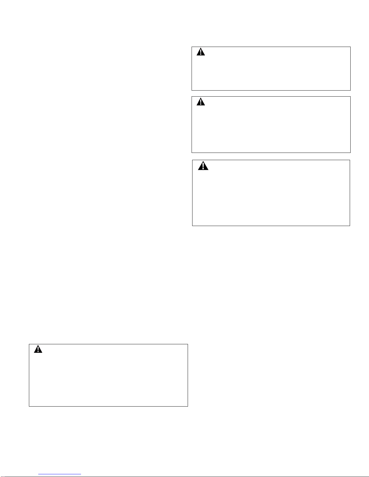
Designation and
Utilization Category
Rated Operational Current Ie (A) at Rated Operational Voltage Ue (V)
24 V
120 V
240 V
380 V
480 V
500 V
600 V
AC15
A300
—
6 A
3 A — — — —
AC15
A500
—
6 A
3 A
1,9 A
1,5 A
1,4 A
—
AC15
A600
—
6 A
3 A
1,9 A
1,5 A
1,4 A
1,2 A
DC13
Q300
2,8 A
0,55 A
0,27 A
— — —
—
Rated thermal current (Ith)
10 A
Sealing
IP67; NEMA 1, 3, 4, 12, 13
Rated impulse withstand (Uimp)
2500 V
Pollution degree
3
Rated insulation voltage (Ui)
300 V, 500 V, 600 V
Operating temperature range
-40 °C to 70 °C [-40 °F to 158 °F]
Short-circuit protective device (type/maximum rating)
Class J fuse (10 A/600 V)
Expected mechanical life
1,000,000 operations
Conditional short-circuit current
1000 A
Electrical rating for gold-plated contacts
10 µA to 100 mA, 1 Vac/Vdc to 50 Vac/Vdc
• Low Voltage Directive 73/23/EEC, as amended by directive 93/68/EEC.
• IEC/EN60947-1, IEC/EN60947-5-1.
• MCTF (Mechanical Life): > 1,000,000 Cycles with Single Sided Confidence Limit of 100%. *
• Proof Test Interval: 1 Year
• Machinery Directive 98/37/EEC only as the directives relate to the components being used in a safety function.
• Sira 08ATEX1073X
• IEC Ex SIR 08.0021X
• MCTF (Electrical Life): > 25,000 Cycles with Single Sided Confidence Limit of 100%. *
• Highest SIL Capability: SIL3 (HFT:1), IEC 61508-2: 2010 * (* APPLICABLE ONLY FOR GSX***A** - * THROUGH GSX***D** - *)
18 sensing.honeywell.com
Page 19

MICRO SWITCH™ GSX Series
Issue 8
50032072
Designation and utilization category
Bezeichnung und Verwendungskategorie
Denominazione e categoria d’impiego
Désignation et catégorie d’utilisation
Rated operational current Ie (A) at rated
operational voltage Ue (V)
Nominaler Betriebsstrom Ie (A) bei nominaler
Betriebsspannung Ue (V)
Corrente nominale di esercizio Ie (A) alla
tensione nominale di esercizio Ue (V)
Courant de fonctionnement nominal Ie (A) à
la tension de fonctionnement nominale Ue(V)
Rated thermal current (Ith)
Nominaler thermischer Strom (Ith)
Corrente termica nominale (Ith)
Courant thermique nominal (Ith)
Rated impulse withstand (U
imp
)
Nominale Impulsspannung (U
imp
)
Resistenza agli impulsi nominale (U
imp
)
Tension nominale de tenue au choc (U
imp
)
Rated insulation voltage (Ui)
Nominale Isolationsspannung (Ui)
Tensione di isolamento nominale (Ui)
Tension d’isolement nominale (Ui)
Short-circuit protective device
(type/maximum rating)
Kurzschluß-Schutzeinrichtung
(Typ/Maximalleistung)
Dispositivo di protezione per cortocircuito
(valore nominale tipico/massimo)
Dispositif de protection contre les courtscircuits (type/valeur nominale maximum)
Conditional short-circuit current
Bedingter Kurzschlußstrom
Corrente di cortocircuito condizionale
Courant de court-circuit conditionnel
Electrical rating for gold-plated contacts
Schaltvermögen von vergoldeten Kontaken
Classificazione elettrica per contatti placcati
oro
Caractéristiques électriques de contacts
plaqués or
Sealing
Schutzart
Grado di protezione
Etanchéité
Pollution degree
Emissionsgrad
Grado di inquinamento
Indice de pollution
Operating temperature range
Betriebstemperaturbereich
Temperature di esercizio
Gamme de températures de fonctionnement
Expected mechanical life
Erwartete mechanische Lebensdauer
Durata meccanica prevista
Durée mécanique prévue
Operations
Schaltspiele
Operazioni
Utilisation
Complies with:
Entspricht:
Conforme con:
Conforme à:
• Intervalle entre essais de sûreté : 1 an
Categoria de designação e utilização
Categoría de designación y utilización
Corrente operacional nominal Ie (A) na
Ue(V)
Ie(A)
Corriente operativa nominal Ie (A) a voltaje
Ue (V)
Corrente térmica nominal (Ith)
정격열전류(Ith)
Corriente térmica nominal (Ith)
额定热电流 (Ith)
Resistência nominal ao impulso (U
)
(U
imp
)
Resistencia de impulso nominal (U
)
U
imp
Tensão de isolamento nominal (Ui)
(Ui)
Voltaje de aislamiento nominal (Ui)
Dispositivo protetor contra curto-circuito
(tipo/nominal máxima)
Dispositivo de protección contra cortocircuito
(tipo/valor nominal)
Corrente condicional de curto-circuito
Corriente condicional de cortocircuito
Classificações elétricas para contatos
banhados a ouro
Clasificación eléctrica para contactos
bañados en oro
镀金触点额定功率
Vedação
밀폐
Sellado
密封
Grau de poluição
Nivel de contaminación
Faixa de temperaturas de operação
Límites de temperatura de funcionamiento
Vida mecânica esperada
Vida mecánica esperada
Operações
Operaciones
Em conformidade com:
• Intervalo do teste de prova: 1 ano
준수사항:
Cumple con:
• Intervalo de prueba de carga: 1 año
符合:
• Low Voltage Directive 73/23/EEC, as
amended by directive 93/68/EEC.
• Machinery Directive 98/37/EEC only as
the directives relate to the components
being used in a safety function.
• Sira 08ATEX1073X
• IEC Ex SIR 08.0021X
• IEC/EN60947-1, IEC/EN60947-5-1.
• MCTF (Mechanical Life): > 1,000,000
Cycles with Single Sided Confidence Limit
of 100%.*
• MCTF (Electrical Life): > 25,000 Cycles
with Single Sided Confidence Limit of
100%.*
• Highest SIL Capability: SIL3 (HFT:1),
IEC 61508-2: 2010 * (* APPLICABLE
ONLY FOR GSX***A** - * THROUGH
GSX***D** - *)
• Proof Test Interval: 1 Year
tensão operacional nominal Ue (V)
imp
• Diretiva de baixa tensão 73/23/EEC,
conforme emendada pela diretiva
93/68/EEC.
• Diretiva de maquinário 98/37/EEC
somente no que se refere aos
componentes usados em função de
segurança.
• Sira 08ATEX1073X
• IEC Ex SIR 08.0021X
• IEC/EN60947-1, IEC/EN60947-5-1.
• MCTF (Vida mecânica): > 1 000 000 de
ciclos com limite de confiança unilateral
de 100%.*
• MCTF (Vida elétrica): > 25 000 de ciclos
com limite de confiança unilateral de
100%.*
• Maior capacidade de SIL: SIL3 (HFT:1),
IEC 61508-2: 2010 * (* APLICÁVEL
SOMENTE PARA GSX***A** - * POR
MEIO DE GSX***D** - *)
• Niederspannungs-Richtlinie 73/23/EG
(in der Fassung der Richtlinie 93/68/EWG)
• Maschinen-Richtlinie 98/37/EWG, soweit
sich diese auf die Komponenten bezieht,
die als Sicherungsvorrichtungen
verwendet werden.
• Sira 08ATEX1073X
• IEC Ex SIR 08.0021X
• IEC/EN60947-1, IEC/EN60947-5-1.
• MCTF (Mechanische Lebensdauer): >
1.000.000 Schaltspiele mit einseitigem
Konfidenzlimit von 100 %.
• MCTF (Elektrische Lebensdauer): >
25.000 Schaltspiele mit einseitigem
Konfidenzlimit von 100 %.
• Höchste SIL-Tauglichkeit: SIL3 (HFT:1),
IEC 61508-2: 2010 * (* GILT NUR FÜR
GSX***A** - * BIS GSX***D** - *)
• Intervall der Abnahmeprüfung: 1 Jahr
지정및활용범주
정격 작동전압
정격임펄스내전압
정격절연전압
단락보호장치(유형/최대등급)
조건부단락전류
도금 접점부의 전기 정격
오염등급
작동온도범위
예상기계 수명
작동
• 저전압규정 73/23/EEC(규정
93/68/EEC 개정).
• 기계류규정
98/37/EEC 만이안전기능에서사용중인구성
요소에대해언급하고있습니다.
• Sira 08ATEX1073X
• IEC Ex SIR 08.0021X
• IEC/EN60947-1, IEC/EN60947-5-1.
• MCTF(기계적수명): 1,000,000
사이클(100%의단면신뢰한계에서)*
• MCTF(전기적수명): >25,000
사이클(100%의단면신뢰한계에서)*
• 최고 SIL 기능: SIL3 (HFT:1), IEC 61508-
2: 2010 * (* GSX***A** - *부터 GSX***D** *까지만 적용)
• 보증 시험 기간: 1 년
에서의정격작동전류
• Direttiva Bassa tensione 73/23/CEE
(emendata dalla Direttiva 93/68/CEE)
• Direttiva macchine 98/37/CEE solo nella
misura in cui la direttiva fa riferimento
ai componenti da utilizzare con funzioni
di sicurezza.
• Sira 08ATEX1073X
• IEC Ex SIR 08.0021X
• IEC/EN60947-1, IEC/EN60947-5-1.
• MCTF (Durata meccanica): >1.000.000
cicli con limite di confidenza su unico lato
del 100%.*
• MCTF (Durata elettrica): >25.000 cicli
con limite di confidenza su unico lato
del 100%.*
• Capacità SIL massima: SIL3 (HFT:1),
IEC 61508-2: 2010 * (* APPLICABILE
SOLO PER GSX***A** - * FINO A
GSX***D** - *)
• Intervallo test di verifica: 1 anno
operativo nominal Ue (V)
imp
• Directiva de bajo voltaje 73/23/EEC,
según la enmienda 93/68/EEC.
• Directiva de maquinarias 98/37/EEC solo
en lo que se refiere a componentes que
se utilizan en una función de seguridad.
• Sira 08ATEX1073X
• IEC Ex SIR 08.0021X
• IEC/EN60947-1, IEC/EN60947-5-1.
• MCTF (Vida mecánica): > 1 000 000 ciclos
con un límite de intervalo de confianza
unilateral de 100 %.*
• MCTF (Vida eléctrica): > 25 000 ciclos
con un límite de intervalo de confianza
unilateral de 100 %.*
• Capacidad de nivel de integridad de la
seguridad (SIL) más elevado: SIL3
(Tolerancia de falla de hardware, HFT:1),
IEC 61508-2: 2010 * (* APLICABLE
SOLO PARA GSX***A** - * HASTA
GSX***D** - *)
• Directive Basse tension 73/23/CEE,
modifiée par la directive 93/68/CEE.
• Directive Machine 98/37/EEC limitée à ce
qui concerne les composants utilisés dans
une fonction de sécurité.
• Sira 08ATEX1073X
• CEI Ex SIR 08.0021X
• CEI/EN60947-1, CEI/EN60947-5-1.
• Nombre moyen de cycles avant la
première défaillance (durée mécanique) :
> 1 000 000 cycles avec limite de
confiance unilatérale de 100 %.*
• Nombre moyen de cycles avant la
première défaillance (durée mécanique) :
> 25 000 cycles avec limite de confiance
unilatérale de 100 %.*
• Niveau SIL maximal : SIL3 (HFT:1), CEI
61508-2: 2010* (* APPLICABLE
UNIQUEMENT POUR LES MODÈLES
GSX***A** - * À GSX***D** - *)
体系及应用类别
额定工作电压
额定冲击耐受 (
额定绝缘电压 (Ui)
短路保护器件(类型/最大等级)
限制短路电流
污染程度
工作温度范围
预期机械寿命
操作
• 低电压指令 73/23/EEC,修订后为
93/68/EEC 指令。
• 机械指令 98/37/EEC,仅限与安全功能中
使用的元件相关的指令。
• Sira 08ATEX1073X
• IEC Ex SIR 08.0021X
• IEC/EN60947-1、IEC/EN60947-5-1。
• MCTF(机械寿命):>1,000,000
个使用周期,单边置信界限为 100%。*
• MCTF(电气寿命):>25,000
个使用周期,单边置信界限为 100%。*
• 具备最高安全完整性等级 (SIL): SIL3
(HFT:1),IEC 61508-2:2010 *(*
仅适用于 GSX***A** - * 至
GSX***D** - *)
• 验证测试间隔:1 年
下的额定工作电流 Ie (A)
)
Honeywell Sensing and Productivity Solutions 19
Page 20

MICRO SWITCH™ GSX Series
Issue 8
50032072
安装尺寸 (仅供参考)
Figure 4. Side rotary head with standard roller Abbildung 4. Seitlicher Drehkopf mit Standard-Rollenhebel
그림4. 표준롤러가있는측면회전헤드
标准滚轮的侧旋转工作头
Figure 5. Pin plunger
그림5. 핀플런저
图
柱塞插脚
Figure 6. Top roller plunger
그림6. 상단롤러플런저
图
顶部滚轮柱塞
Figure 7. Top roller lever
그림7. 상단롤러레버
图
顶部滚轮操作柄
MOUNTING DIMENSIONS (for reference only) EINBAUMASSE (nur als Richtwerte)
DIMENSIONI DI MONTAGGIO (misure di riferimento) DIMENSIONS DE MONTAGE (à titre indicatif)
DIMENSÕES PARA MONTAGEM DIMENSIONES DE MONTAJE (solo para consulta)
(apenas para referência)
Figura 4. Testa rotante laterale con rullo standard Figure 4. Tête à rotation latérale avec galet standard
Figura 4. Cabeçote giratório lateral com roldana padrão
Figura 4. Cabezal de rotación lateral con rodillo estándar 图4.
Abbildung 5. Stiftstößel
Figura 5. Pulsante
Figure 5. Poussoir à broche
Figura 5. Pino atuador
Figura 5. Émbolo con pin
5.
Abbildung 6. Oberer Rollenstößel
Figura 6. Pulsante a rotella superiore
Figure 6. Poussoir à galet supérieur
Figura 6. Êmbolo superior com roldana
Figura 6. Émbolo con rodillo superior
6.
Abbildung 7. Oberer Rollenhebel
Figura 7. Leva a rotella superiore
Figure 7. Levier à galet supérieur
Figura 7. Alavanca superior com roldana
Figura 7. Palanca con rodillo superior
7.
20 sensing.honeywell.com
Page 21

MICRO SWITCH™ GSX Series
Issue 8
50032072
Honeywell Sensing and Productivity Solutions 21
Page 22

MICRO SWITCH™ GSX Series
WARRANTY/REMEDY
Honeywell warrants goods of its manufacture as being free of defective
materials and faulty workmanship. Honeywell’s standard product
warranty applies unless agreed to otherwise by Honeywell in writing;
please refer to your order acknowledgement or consult your local sales
office for specific warranty details. If warranted goods are returned to
Honeywell during the period of coverage, Honeywell will repair or
replace, at its option, without charge those items it finds defective. The
foregoing is buyer’s sole remedy and is in lieu of all other
warranties, expressed or implied, including those of
merchantability and fitness for a particular purpose. In no event
shall Honeywell be liable for consequential, special, or indirect
damages.
While we provide application assistance personally, through our
literature and the Honeywell web site, it is up to the customer to
determine the suitability of the product in the application.
Specifications may change without notice. The information we supply
is believed to be accurate and reliable as of this printing. However, we
assume no responsibility for its use.
SALES AND SERVICE
Honeywell serves its customers through a worldwide network of sales
offices, representatives and distributors. For application assistance,
current specifications, pricing or name of the nearest Authorized
Distributor, contact your local sales office or:
E-mail: info.sc@honeywell.com
Internet: sensing.honeywell.com
Phone and Fax:
Asia Pacific +65 6355-2828
+65 6445-3033 Fax
Europe +44 (0) 1698 481481
+44 (0) 1698 481676 Fax
Latin America +1-305-805-8188
+1-305-883-8257 Fax
USA/Canada +1-800-537-6945
+1-815-235-6847
+1-815-235-6545 Fax
GARANTIE/ANSPRÜCHE
Honeywell garantiert, dass alle Waren aus eigener Herstellung zum
Zeitpunkt der Lieferung frei von Material- und Fertigungsfehlern sind.
Sofern keine abweichende schriftliche Vereinbarung mit Honeywell
vorliegt, gilt die Standard-Produktgarantie von Honeywell. Details zur
Garantie können Sie der Auftragsbestätigung entnehmen oder bei
einer Verkaufsniederlassung in Ihrer Umgebung erfragen. Wenn
Produkte im Garantiezeitraum an Honeywell zurückgesendet werden,
wird Honeywell diese nach eigenem Ermessen austauschen
reparieren. Das Vorstehende bildet den einzigen Anspruch des
Käufers, alle sonstigen ausdrücklichen und konkludenten
Garantien – einschließlich der Handelsüblichkeit und der
Zusicherung der Eignung für einen bestimmten Zweck – sind
ausgeschlossen. Unter keinen Umständen haftet Honeywell für
Folgeschäden, Sonderschäden oder indirekte Schäden.
In anwendungsspezifischen Fragen sind wir bemüht, über die
Honeywell-Website, mit technischen Unterlagen und auch persönlich
Hilfestellung zu leisten. Dennoch liegt es in der alleinigen
Verantwortung des Kunden, die Eignung des Produkts für ein
bestimmtes Anwendungsgebiet zu beurteilen.
Technische Änderungen ohne Ankündigung vorbehalten. Die
Informationen in dieser Veröffentlichung wurden mit größter Sorgfalt
zusammengestellt. Dennoch können wir keine Verantwortung für
Schäden übernehmen, die sich aus der Nutzung dieser Informationen
ergeben.
Issue 8 50032072
VERTRIEB UND SERVICE
Honeywell bietet Service über ein weltweites Netz von
Vertriebsniederlassungen, Vertretern und Distributoren an. Wenden
Sie sich mit Fragen zu Anwendungsgebieten, technischen Daten,
Preisen und Namen der nächstgelegenen autorisierten Distributoren
an Ihr regionales Vertriebsbüro oder:
E-Mail: info.sc@honeywell.com
Internet: sensing.honeywell.com
Telefon und Fax:
Fernost +65 6355-2828
+65 6445-3033 Fax
Europa +44 (0) 1698 481481
+44 (0) 1698 481676 Fax
Lateinamerika +1-305-805-8188
+1-305-883-8257 Fax
USA/Kanada +1-800-537-6945
+1-815-235-6847
+1-815-235-6545 Fax
GARANZIA
Honeywell garantisce che i propri prodotti sono privi di difetti relativi ai
materiali e alla realizzazione. Se non diversamente specificato da
Honeywell per iscritto, ha validità la garanzia standard di Honeywell.
Per i dettagli specifici, fare riferimento alla conferma dell’ordine o
rivolgersi all’ufficio commerciale di zona. Se i prodotti vengono restituiti
a Honeywell durante il periodo di validità della garanzia, Honeywell
ripara o sostituisce, a sua discrezione e gratuitamente, gli elementi
difettosi. Quanto sopra riportato costituisce l’unica garanzia per
l’acquirente e sostituisce qualsiasi altra garanzia, espressa o
implicita, incluse, tra le altre, quelle di commerciabilità e idoneità
per uno scopo particolare. In nessun caso Honeywell sarà
ritenuta responsabile di danni consequenziali, speciali o indiretti.
Sebbene Honeywell fornisca assistenza, tramite documenti specifici e
il sito Web dell’azienda, è responsabilità del cliente determinare se il
prodotto è adatto all’ambiente operativo.
Le specifiche sono soggette a modifica senza preavviso. Le
informazioni contenute in questa pubblicazione sono considerate
accurate e aggiornate alla data di stampa. Tuttavia, Honeywell non si
assume alcuna responsabilità per il relativo utilizzo.
VENDITA E ASSISTENZA
Honeywell serve i propri clienti attraverso una rete mondiale di uffici
commerciali, rappresentanti e distributori. Per assistenza con le
applicazioni e informazioni sulle specifiche correnti, sui prezzi o sul più
vicino rivenditore autorizzato, rivolgersi all’ufficio commerciale della
propria zona oppure utilizzare i seguenti contatti:
Email: info.sc@honeywell.com
Internet: sensing.honeywell.com
Telefono e fax:
Asia-Pacifico +65 6355-2828
+65 6445-3033 Fax
Europa +44 (0) 1698 481481
+44 (0) 1698 481676 Fax
America Latina +1-305-805-8188
+1-305-883-8257 Fax
USA/Canada +1-800-537-6945
+1-815-235-6847
+1-815-235-6545 Fax
22 sensing.honeywell.com
Page 23

MICRO SWITCH™ GSX Series
Issue 8
50032072
보증/구제책
앞서말한것은구매자의독자적인구제
책으로,제품무결성및합목적성에대한명시적, 묵시적 보증(단, 이에
국한되지 않음)을 포함한 기타 모든 보증을대신합니다. 하니웰은어떠한
경우에도결과적, 간접적손해또는특수한손해에대한책임을지지않습니다
영업및서비스
이메일
인터넷
전화및팩스
GARANTIE / RECOURS
Honeywell garantit les marchandises de sa fabrication contre tout
défaut de pièce ou de main-d’œuvre. La garantie de produit standard
Honeywell s’applique sauf autre accord écrit par Honeywell ; reportezvous à votre accusé de réception de commande ou consultez votre
bureau commercial local pour obtenir des informations détaillées sur la
garantie spécifique. Si vous retournez les marchandises à Honeywell
pendant leur période de garantie, Honeywell réparera ou remplacera, à
sa discrétion, gratuitement les éléments constatés défaillants. Cette
procédure est le seul recours de l’acheteur et remplace toute
garantie, explicite ou implicite, y compris celle relative à la qualité
et à l’adéquation à un usage particulier. En aucun cas, Honeywell
ne pourrait être tenue pour responsable des dommages
consécutifs, spéciaux ou indirects.
Bien que nous fournissions une assistance aux applications par le
biais de notre bibliographie et du site Internet de Honeywell, il
appartient au client de déterminer l’adéquation du produit à son
application.
Les caractéristiques peuvent être modifiées sans préavis. Les
informations que nous diffusons sont réputées précises et fiables au
moment de leur impression. Nous n’assumons cependant aucune
responsabilité quant à leur usage.
VENTE ET SERVICE APRES-VENTE
Honeywell sert ses client pas l’intermédiaire d’un réseau mondial de
bureaux de vente, de représentants et de distributeurs. Si vous avez
besoin d’assistance, voulez connaître les caractéristiques actuelles,
obtenir un prix ou le nom du distributeur autorisé le plus proche,
contactez le bureau de vente local ou :
E-mail : info.sc@honeywell.com
Internet : sensing.honeywell.com
Téléphone et télécopieur :
Asie Pacifique +65 6355-2828
+65 6445-3033 Télécopieur
Europe +44 (0) 1698 481481
+44 (0) 1698 481676 Télécopieur
Amérique Latine +1-305-805-8188
+1-305-883-8257 Télécopieur
Etats-Unis/Canada +1-800-537-6945
+1-815-235-6847
+1-815-235-6545 Télécopieur
GARANTIA/SOLUÇÕES
A Honeywell garante seus produtos contra defeitos de material e de
fabricação. A garantia padrão de produto da Honeywell se aplica a
menos que haja um acordo diferente por escrito com a Honeywell;
consulte a sua confirmação de encomenda ou consulte o escritório de
vendas local para obter detalhes específicos da garantia. Se produtos
na garantia forem devolvidos para a Honeywell durante o período de
cobertura, a empresa, conforme seus critérios, reparará ou substituirá
os itens considerados defeituosos.
solução oferecida ao comprador e substitui quaisquer outras
garantias, expressas ou implícitas, inclusive garantias de
comercialização e adequação a um fim específico. Em hipótese
alguma a Honeywell deve ser responsabilizada por danos
consequenciais, especiais ou indiretos.
Embora a Honeywell proporcione assistência pessoal, através de
literatura e de seu site na web, cabe ao cliente determinar qual
produto é mais adequado à sua aplicação.
Especificações podem ser alteradas sem aviso prévio. Acreditamos
que as informações aqui contidas eram as mais precisas e confiáveis
no momento da impressão desta publicação. No entanto, não
assumimos qualquer responsabilidade pelo uso destas informações.
A Honeywell atende seus clientes através de uma rede mundial de
escritórios e representantes de vendas, bem como de distribuidores.
O acima estipulado é a única
Para obter assistência com sua aplicação, especificações atuais,
preços ou nome do Revendedor Autorizado mais próximo, entre em
contato com seu escritório de vendas local ou:
info.sc@honeywell.com
E-mail:
Internet:
Telefone e fax:
EUA/Canadá +1-800-537-6945
Internacional +1-815-235-6847; +1-815-235-6545 Fax
하니웰은자사에서제조한제품에결함있는재료및잘못된공정이없음을보
증합니다.하니웰이달리서면으로합의한경우를제외하고는하니웰의표준
제품보증이적용됩니다.
구체적인보증정보는주문정보를참고하거나해당지역의영업지사에문의
하십시오.보증기간중에보증의적용을받는제품을하니웰에반품할경우하
니웰은자체적인판단에따라결함이있는것으로판단되는품목에대해무료
수리또는교체서비스를제공합니다.
하니웰은문서나웹사이트를통해제품사용에관한지원을제공하고있지
만제품을어떤환경에서응용할것인지결정하는것은전적으로고객의몫입
니다.
사양은사전통지없이변경될수있습니다.하니웰이제공하는정보는본문서
를기준으로정확하고신뢰할만한것으로간주됩니다.하지만이러한정보의
사용에대해서는하니웰이어떠한책임도지지않습니다.
하니웰은영업점및담당자, 유통업체가연결된세계적인네트워크를통해
고객서비스를제공합니다.제품사용지원, 현재사양, 가격 또는가까운
공인유통업체명은해당지역의영업점이나 아래 연락처로문의하십시오.
아시아태평양 +65 6355-2828
+65 6445-3033 (팩스)
유럽 +44 (0) 1698 481481
+44 (0) 1698 481676 (팩스)
라틴아메리카 +1-305-805-8188
+1-305-883-8257 (팩스)
미국/캐나다 +1-800-537-6945
+1-815-235-6847
+1-815-235-6545 (팩스)
sensing.honeywell.com
: info.sc@honeywell.com
: sensing.honeywell.com
:
.
Honeywell Sensing and Productivity Solutions 23
Page 24

MICRO SWITCH™ GSX Series
Issue 8
50032072
honeywell.com
Copyright © 2015 Honeywell International Inc. All rights reserved.
保证/补救
上述条款是购买人所能获得的唯一补救方法,并取代所
有其他明示或暗指的保证,包括有关针对某一特定目的的适销性和适用
性的保证。霍尼韦尔对衍生性损害、特殊损害与间接损害概不负责。
销售与服务
发送电子邮件至:
通过网站联系:
电话和传真:
CLAUSULA DE GARANTÍA
Honeywell garantiza que los productos que fabrica no presentan
defectos de mano de obra ni de materiales. La garantía del producto
estándar de Honeywell se aplicará a menos que Honeywell convenga
otra cosa por escrito; lea su confirmación de pedido o consulte a su
oficina local de ventas para obtener detalles específicos de la garantía.
Si se devuelven productos con garantía a Honeywell durante el período
de cobertura, Honeywell los reparará o reemplazará, según su criterio
y elección, si determina que presentan defectos. Esta cláusula de
garantía sustituye cualquier otra garantía, sea explícita o implícita,
incluidas las de comercialización y aptitud para un uso específico.
En ningún caso Honeywell será responsable por daños
consecuentes, especiales o indirectos.
Aunque Honeywell ofrece asistencia personal para las aplicaciones
por medio de sus publicaciones y páginas web, es el cliente quien
debe determinar la idoneidad del producto en la aplicación.
Las especificaciones pueden cambiar sin previo aviso. La información
suministrada es considerada correcta y fiable al momento de su
impresión. No obstante, no asumimos la responsabilidad por su uso.
VENTAS Y SERVICIO
Honeywell dispone de una red mundial de oficinas de ventas,
representantes y distribuidores para atender a sus clientes. Para
solicitar asistencia con las aplicaciones, especificaciones actuales,
precios o el nombre del Distribuidor autorizado más cercano, póngase
en contacto con la oficina de ventas más cercana o utilice los
siguientes medios:
Correo electrónico: info.sc@honeywell.com
Internet: sensing.honeywell.com
Teléfono y fax:
Asia y el Pacífico +65 6355-2828
+65 6445-3033 (fax)
Europa +44 (0) 1698 481481
+44 (0) 1698 481676 (fax)
América Latina +1-305-805-8188
+1-305-883-8257 (fax)
EE. UU./Canadá +1-800-537-6945
+1-815-235-6847
+1-815-235-6545 (fax)
霍尼韦尔保证,本公司所制造的产品不存在任何有缺陷的材料和工艺上
的缺陷。如霍尼韦尔未另外以书面形式同意,则适用霍尼韦尔的标准产
品保证;请参阅订单确认书或咨询当地销售处了解具体保修细节。如果
用户在保修期内将产品退回公司,霍尼韦尔将负责免费维修或更换存在
缺陷的零部件。
尽管我们可以派专人、通过我们的技术资料和霍尼韦尔网站等方式提供
应用支持,但确定产品在应用中是否适合则取决于用户自身。
技术规格若有改动恕不另行通知。本文所提供的信息自印刷之日起均视
为准确、可靠。但是,我们不对本文的使用承担任何责任。
霍尼韦尔通过其遍布全球的销售办事处、代理商和分销商网络为客户提
供服务。如需获得应用支持、了解最新技术规格、价格或离您最近的授
权分销商的名称,请联系当地的销售办事处或:
亚太区 +65 6355-2828
传真 +65 6445-3033
欧洲 +44 (0) 1698 481481
传真 +44 (0) 1698 481676
拉美区 +1-305-805-8188
传真 +1-305-883-8257
美国/加拿大 +1-800-537-6945
+1-815-235-6847
传真 +1-815-235-6545
info.sc@honeywell.com
sensing.honeywell.com
Sensing and Productivity Solutions
Honeywell
1985 Douglas Drive North
Golden Valley, MN 55422
50032072-8-ML IL50 GLO Printed in USA
October 2015
 Loading...