

Page 1

Honeywell Process Solutions
Mercury Modem
User Manual
October 2010
V 1.02
Honeywell
Page 2

MI Modem
Telecom Requirements
Telecom Requirements
The Mercury modem does not fully meet Telecom's impedance requirements.
Performance limitations may occur when used in conjunction with some parts of the
Network. Telecom will accept no responsibility should difficulties arise in such
circumstances.
The transmit level from this device is set at a fixed level and because of this there may
be circumstances where the device does not give its optimum performance. Before
reporting such occurrences as faults, please check the line with a standard
Telepermitted telephone, and do not report a fault unless the telephone performance
is impaired
2
www.honeywell.com
Page 3

MI Modem
FCC PART 68
The Mercury modem is registered with the FCC (Federal Communications Commission) under Part 68. The Part 68 rules require that the following information be
provided to the end user of equipment containing a DAA:
FCC Notice to the Users
1. UPON REQUEST ONLY, you must provide the following data to your
telephone utility company (telco):
a) Notice of intention to install or permanently remove an FCC Part
b) *The Ringer Equivalence Number (REN) (see device label).
c) *The (USOC) jack type to be provided by the telco. Typically
*The *-flagged items above are noted on the equipment's FCC Compliance label.
2. This device may not be used on telco-operated coin phone lines. Party
lines and privately owned coin-phones are subject to local State regulatory
policies, and possible additional State special requirements.
3. The telco has the right to make changes to their network which may affect
the operation of your equipment, provided you are given adequate
advance written notice to permit correct operation.
4. In case of operational problems, disconnect your unit by removing the
modular plug from the telco jack. If your regular phone (or other device
or system) still works properly, your Mercury Modem has a problem and
must remain disconnected and (officially) serviced or returned for
repairs. If upon the above disconnection your regular service still has
problems, notify your telco that they may have a problem. Request prompt
service at no cost to you the user. If a problem is found in premises wiring
not telco-installed wiring, you may be subject to a service call charge.
5. Unless otherwise noted in the User's Manual (e.g.: fuses, etc.), user may
not under any circumstances (in or out of warranty) attempt any service,
adjustments or repairs on this unit. It must be returned to the factory or
authorized U.S. service agency for all such work. Locations (or phone
numbers) of factory or authorized U.S. service points are listed in this
user's manual.
6. Special FCC rules apply to equipment connected behind a PBX or KTS.
68 registered device or system, and the *FCC Registration
Number.
Note that if several devices are connected to the same line, the
RENs must not add up to more than 5.0 (A or B). This REN
figure is important to your telco.
this will be RJ-11 C/W for single lines.
3
Page 4

MI Modem
CS-03
nated by the supplier. Any repairs or alterations made by the user to this equipment,
NOTICE: The Industry Canada label identifies certified equipment. This
certification means that the equipment meets telecommunications network protective, operational and safety requirements as prescribed in the appropriate Terminal
Equipment Technical Requirements document(s). The Department does not
guarantee the equipment will operate to the user's satisfaction.
Before installing this equipment, users should ensure that it is permissible to be
connected to the facilities of the local telecommunications company. The
equipment must also be installed using an acceptable method of connection. The
customer should be aware that compliance with the above conditions may not
prevent degradation of service in some situations.
Repairs to certified equipment should be coordinated by a representative desig-
or equipment malfunctions, may give the telecommunications company cause to
request the user to disconnect the equipment.
Users should ensure for their own protection that the electrical ground connections
of the power utility, telephone lines and internal metallic water pipe system, if
present, are connected together. This precaution may be particularly important in
rural areas.
Caution: Users should not attempt to make such connections themselves, but
should contact the appropriate electric inspection authority, or electrician, as
appropriate.
NOTICE: The Ringer Equivalence Number (REN) assigned to each device
provides an indication of the maximum number of terminals allowed to be
connected to a telephone interface. The termination on an interface may consist
of any combination of devices subject only to the requirement that the sum of the
Ringer Equivalence Numbers of all the devices does not exceed 5. The Mercury
Modem REN is 0.3A.
4
www.honeywell.com
Page 5

MI Modem
Table of Contents
FCC Part 68......................................................................3
CS-03...............................................................................4
Mercury Modem...............................................................6
Modem Layout.................................................................7
Mounting the Integral Modem (ECAT-PT).....................12
Mounting the Integral Modem (ER).................................15
Verification.....................................................................17
External Mercury Modem...............................................19
Basic External Mercury Modem.....................................20
Mercury Modem Barrier Box..........................................21
Wiring Diagram for Mercury Modem...............................22
Modem Expansion Board................................................23
Adding a Modem Expansion Board.................................24
Modem Expansion Board Layout....................................25
Configuring the Modem..................................................26
Modem Configuration (DOS).........................................27
Modem Configuration (Windows)...................................34
Installation in Division 2 Hazardous Locations (UL).........46
Installation in Division 2 Hazardous Locations (CSA)......48
Need Help?.....................................................................50
Technical Support...........................................................53
List of Figures.................................................................54
Index..............................................................................55
5
Page 6

MI Modem
Mercury Modem
Designed for harsh environment operations, the Mercury Modem provides
for remote instrument access and data collection. The modem board can
enclosure as a stand-alone modem. Stand-alone modems may also include
The standard modem configuration is a single channel, battery-operated
incorporated to provide reliable operation. Circuit board jumpers permit
setting the local baud rate for the connected instrument to be different than
the modulated baud rate. This feature permits leaving the instrument's
Alkaline Receptacle Pack, but an optional Lithium Power Pack may be
DC Power Supply with battery backup is also available as
accessed by a single modem on one phone line. Modem port-switching is
handled automatically by the software when using Mercury Instruments'
be retrofitted inside existing ECATs and ERs or installed into a separate
a variety of I.S. Barriers, power options and multi-port operation.
Instruments connected to a Mercury Modem may be called by host
computer systems to retrieve data, or the modem can call in utilizing
Mercury Instruments' Alarm-Link software when an instrument alarm
occurs.
2400 baud field modem. On-board surge protection components are
baud rate set at 9600 baud for direct connections with a laptop even
though the modem operates at 2400 baud.
The modem comes standard with either an Alkaline Disposable Pack or
substituted. A
an option for locations where AC power is available.
An optional expansion board permits three additional serial ports (and
alarm channels) to be added so that a total of four instruments may be
Link software packages. When using the multi-port feature, it is not
necessary that the instruments or devices be of the same type.
6
www.honeywell.com
Page 7
MI Modem
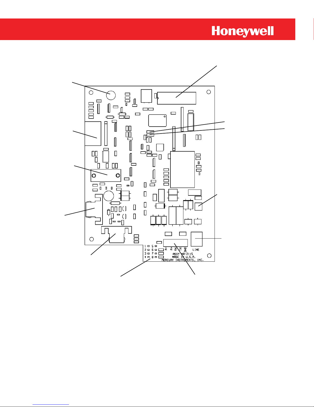
(2)
Thumbscrew
Hole
(11)
J1
Expansion
Board
Connector
(3)
J2
DE-9S
Socket
Connector
for
Config.
Cable
(4)
J3
Battery
Connector
(5)
J4
Battery
Connector
Modem Layout
(6)
LED Status Indicators
(1)
U20
Modem
Firmware
(10)
JP4 &
JP5
Baud
Rate
Jumper
(9)
TB2
Protective
Ground
Lug
(8)
J5
RJ11
Phone
Jack
(7)
TB1
Serial Port
Hookup
Figure 1
7
Page 8

MI Modem
Modem Layout
This hole is used when the integral modem is installed
1. Modem Firmware:
2. Thumbscrew Hole:
3. J2, DE-9S Socket Connector:
4. J3, Battery Connector:
5. J4, Battery Connector:
The firmware EPROM (U20) is removable for
firmware upgrades.
into a Mercor ECAT. The Thumbscrew 20-8715 is
provided in the installation kit.
This connector is used to configure the Modem.
This Battery Connector can be used when the integral
modem is installed into a Mercury Electronic
Recorder or Mercor ECAT.
This Battery Connector can be used when the integral
modem is installed into a Mercor ECAT or Mercury
Electronic Recorder.
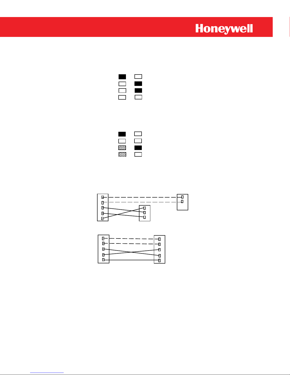
6. LED Status Indicators:
1 - Power 5 - N/A
2 - OFF HOOK 6 - Alarm
3 - Carrier 7 - Port "A" Select
4 - TX To Host 8 - RX From Host
The following LED Indicators will go through three states:
8
www.honeywell.com
Page 9
MI Modem
Power Up and Self Test:
When power is first applied to the Modem LED #1, #6 and
#7 will light up and stay lit for about three seconds. Ignore
LED #4 and #8; their states are not set and will change during
power up.
1 5
2 6
3 7
4 8
Standby:
LED #4 then LED #3 will light up momentary and then go
off; LED #1 and #7 will light up and stay lit for about six
seconds then go off.
1 5
2 6
3 7
4 8
Power Down:
All LEDs' are off.
7. TB1, Modem Hookup:
Modem TB1 ECAT PULSE BRD
AA+
RX
TX
GND
SCIB TB1
C
T
R
AA+
Modem TB1 ER, Mainboard TB1
AA+
RX
TX
GND
AA+
RX
TX
GND
9
Page 10

MI Modem
8. J5, RJ11 Phone Jack:
For convenience, it is suggested that the instrument
with the integral modem be mounted near a telephone
telephone line surge suppression components on the
line drop that is easily suited for installation of an
electrical earth ground. The instrument/modem
assembly must be mounted in a "safe area" (as
opposed to "hazardous area") in accordance with
Mercury Instruments guide lines for modem
installation.
9. TB2, Grounding Lug:
This terminal provides a direct connection to the
modem board. It should be connected via a short
length of wire to an enclosure ground terminal located
nearby.
Note: The best protection against lightning surges is a telephone line
surge suppressor (TII) installed at the service terminals.
10
www.honeywell.com
Page 11
MI Modem
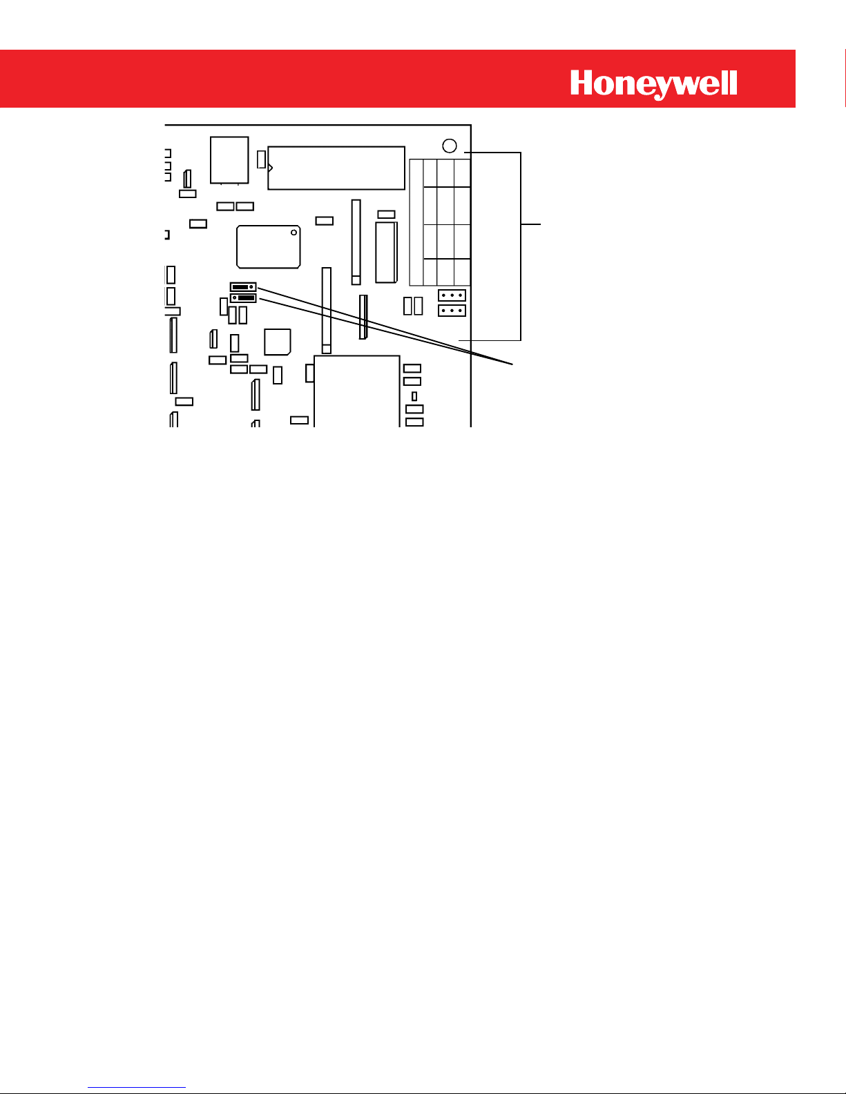
JP4
Figure 2
10. JP4 & JP5 Baud Rate Jumpers:
To change the baud rate between the modem and the
instrument, locate the baud rate table on the upper right
hand side of the modem main circuit board. Move the
jumpers on JP4 and JP5 the appropriate position.
Insure that the Instrument Baud Rate (Item 126 in the
Mercor ECAT and Mini or Item 588 in the Electronic
Recorder) is set the baud rate corresponding with the
modem jumper settings.
I
I
I
I
I
I
BAUD RATE
12 24 96 192
II
123
JP5
JP4 & JP5
Baud Rate
Jumpers
(Jumpers set
at 9600 baud)
Baud Rate
Jumper
silkscreen
11. Expansion Board Connector:
Attach the expansion board cable to the modem by
plugging the keyed connector (without the vinyl pulltab) into this connector (red stripe down). For more
information on the Expansion Board refer to page 22.
11
Page 12
MI Modem
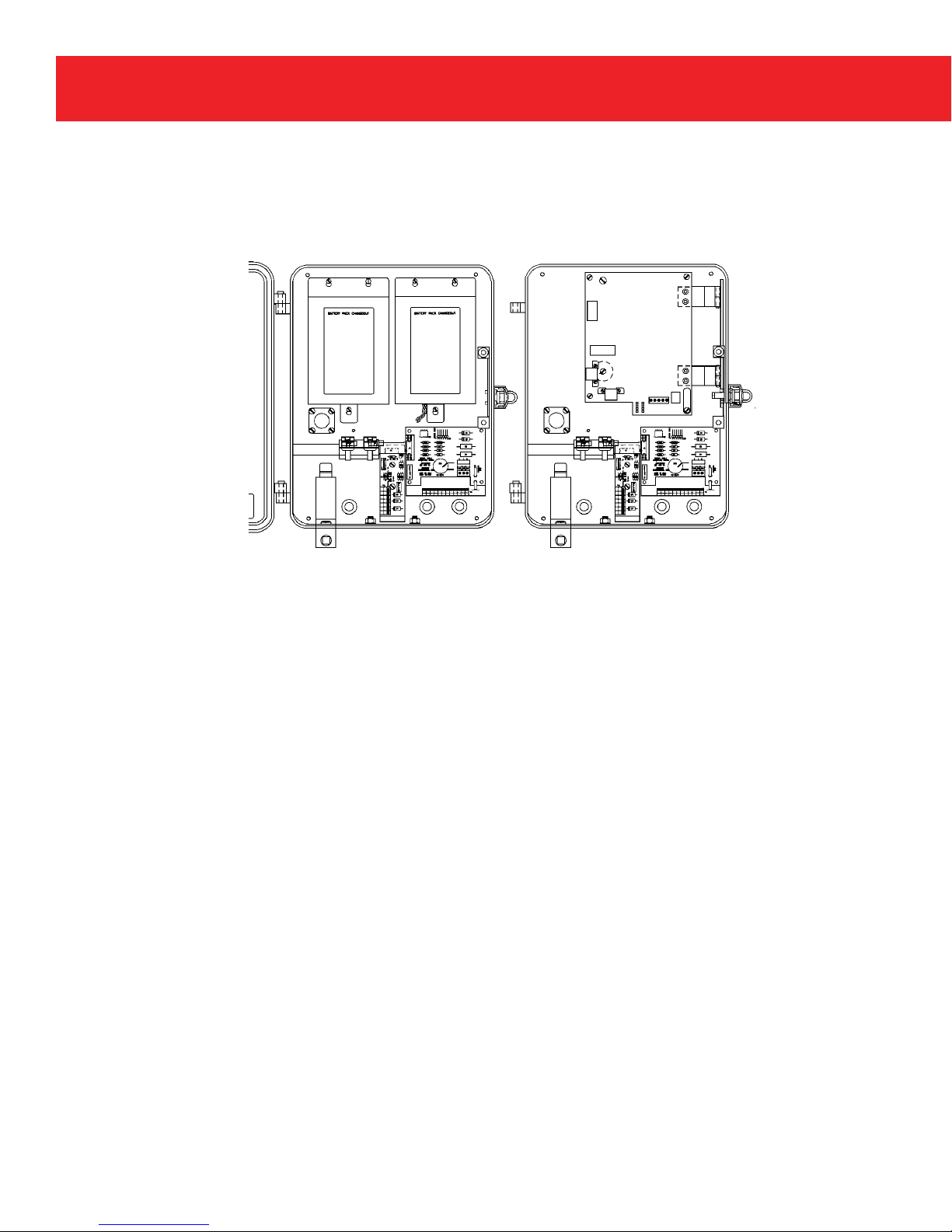
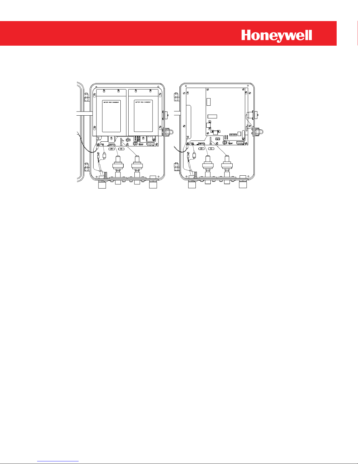
Mounting the Integral Modem
(ECAT-PT)
Before Installation After Installation
Figure 3
Mercury Modem with
Main Batteries not
shown for clarity
1. Start the AT-Link Software package and under Instrument
on the main menu line, select Shutdown. All data is stored in
memory and the instrument is not obtaining data.
2. When Shutdown is complete, reach inside the instrument and
unplug the main battery plug.
3. Remove any battery or power supply mounted in the righthand position.
4. Remove the (2) hex nuts holding the door latch to the case. Do
not remove the latch or chassis bumper assembly.
12
www.honeywell.com
Page 13

MI Modem
Mounting (ECAT-PT)
5. The Modem Assembly attaches to the (2) door latch screws in
place of the nuts. Position the Modem Assembly against the
right side of the case so that the (2) screw holes in the hinge
mounting bracket are aligned with the latch screws. With the
bumper assembly positioned between the case and the hinge
mounting bracket, tighten the (2) latch screws into the mount
ing bracket. Some adjustment of the bumper assembly may be
necessary to ensure correct alignment with the chassis. When
installed, the lower hinge on the Modem Board Carrier Plate
should swing between the upper bumper pad and the chassis
latch post.
6. If a battery or power supply is installed in the left-hand
position, remove the upper-right mounting screw.
7. Install (1) 60-1237 #6-32 x 3/4 Binding Head Screw (provided
in kit) in this hole from the outside of the case.
8. Install (1) 20-8673 Mounting Post (provided in kit) on the
60-1237 screw with the slotted end facing out. The post is
slotted for screwdriver use in tightening or loosening. The
battery or power supply must be in place before this post is
installed.
9. Install the 20-8715 Thumbscrew (provided in kit) into the
retainer located in the upper left corner of the Modem PC
Board. Tighten the thumbscrew until the carrier plate seats
against the mounting post.
10. Attach the small 20-8731 Part 68 Certification Label (provided
in kit) to the outside of the instruments case on the hinge side.
13
Page 14

MI Modem
Mounting (ECAT-PT)
11. Attach the 20-8723 Status Indicator Label to the chassis
backplate in the upper right corner or the inside bottom surface
the phone jack located on the lower right corner of the modem
12. Insert the phone hookup wire through the Hubbell connector
13. Install the RJ11 connector on the phone wire and plug it into
14. Verify that the hinged Modem Board Carrier Plate swings
15. Connect the GND, TX and RX from the modem to the SCIB
of the case.
or conduit connector located on the right side of the ECAT.
board. Route the phone wire through the cable clip on the
hinge mounting bracket and down the right side between the
Output Pulse Board stack and the case to avoid interference
with the wiring.
without interference with cables or plugs on the Output Pulse
Board stack. Reposition any that come in contact with the
Carrier Plate. If necessary, the position of the hinges on the
hinge mounting bracket can be adjusted to eliminate
interference.
as shown on page 9 TB1 Modem Hookup.
14
16. Reinstall and reconnect all batteries. Press the MI button, and
enter the access code. Display Item Code 126, Instrument
Baud Rate and insure that it is set to code 2, (2400 baud) for
modems with firmware 1.3x. Set to code 0, (9600 baud) for
modems with firmware 2.xx. Press Exit twice to return to the
corrector mode.
17. Verify the Jumpers on J4 & J5 installation matches the EC-
AT's baud rate set in item 126.
www.honeywell.com
Page 15
MI Modem
Mounting the Integral Modem (ER)
Before Installation After Installation
Mercury Modem with
Main Batteries not
shown for clarity
Figure 4
1. Start the ER-Link Software package and select Instrument,
then select Shutdown. After the link is disconnected
escape to clear the dialog box and select Disconnect Link.
2. When Shutdown is complete, reach inside the instrument and
unplug the main battery plug.
3. Remove the battery mounting plate by loosening the (4) screws
and lift the battery plate up and out.
4. Remove the screws from the (4) corners of the ER main board.
15
Page 16

MI Modem
Mounting (ER)
5.
Install (4) 20-8554 1/2" M-F Standoff (provided in kit) in main
be reattached using the lower left corner screw. Do not tighten
head screws and lowering the plate until its seats on the screws.
inside the ER. Suitable locations would be on the inside of the
Reinstall the ER battery plate and tighten the mounting screws.
board corner screw holes.
6. Install (1) 60-1210 #6-32 x 3/8 Fillister Head Screw in each
of the (4) 1/2" standoffs. The ground wire from the door must
the screws at this time.
7. Install the Modem Board Carrier Plate Assembly (provided in
kit with PCB installed) by placing the slots over the fillister
8. Attach the small 20-8731 Part 68 Certification Label
9. Attach the 20-8723 Status Indicator Label in a visible location
10. Insert the phone hookup wire through the Hubbell connector
11. Install the RJ11 connector on the phone wire and plug it into
12. Connect the modem GND, TX and RX to the ER main
Tighten the (4) fillister head screws.
(provided in kit) to the outside of the case on the hinge side.
door, or the back or bottom surfaces inside the case.
or conduit connector located on the right side of the ER.
the phone jack located on the lower right corner of the modem
board. Route the phone wire through the cable clip attached
to the modem board and down the right side to avoid
interference with the field wiring on the ER main board.
board as shown on page 9 TB1 Modem Hookup.
13.
Reconnect all batteries.
16
www.honeywell.com
Page 17

MI Modem
Verification (DOS)
To verify that the installation of the integral modem was successful
and the instrument is working properly, obtain a modem link with
the instrument using ER-Link or AT-Link DOS software package.
Start either the AT-Link or ER-Link (depending on the type of unit the
modem was installed in). Select Computer on the main menu line
and press Enter.
With Computer Communication highlighted, press Enter. Insure
that the Modem Baud Rate is set for 2400 baud. Check to see if the
correct Modem Port is selected and that it matches the port on the
computer.
Next move to the Transfer selection on the main menu line and press
Enter. Select Modem Link from the sub-menu options and press
Enter. Enter the Site Phone Number and press Enter.
If the modem was installed correctly, the NOT LINKED message
located in the lower left-hand corner of the computer screen will
change to MODEM LINK.
Verification (Windows)
To verify that the installation of the integral modem was successful
and the instrument is working properly, obtain a modem link with
the instrument using ER-Link or AT-Link for Windows software
package.
Start either the AT-Link or ER-Link (depending on the type of unit the
modem was installed in). Select Setup on the main menu line, then
click on Site List.
17
Page 18

MI Modem
With the Site List dialog box open, click on Add and enter the required
Both the DOS and Windows verification will activate the LEDs on the
battery power, the LEDs are not illuminated when the modem switches
report instrument alarms as they occur. If a call fails to connect to the
devices) may be connected to the modem using the optional expansion
information. Insure that the Site Name, Site Location, Site Phone,
Site ID, Site ID 2, Instrument Access Code and Mercury Modem
Port are correct. Click OK , then click EXIT when completed.
Next select Communications under Setup on the main menu line.
Insure that the Modem Connection Baud Rate is set for 2400 baud.
Check to see if the correct Connector is selected and that it matches
the port on the computer. Initially, try making the first call with the
Modem Init String blank. If the call fails, most likely the host
modem's profile is incompatible. Refer to Need Help on page 47 for
further information.
Select Transfer on the main menu line or click on the "Phone" Icon
on the productivity bar. With the Modem Link dialog box open,
single click on the site to call, then click on Start Modem Link.
The message at the bottom right hand side of the screen should read;
Dialing XXXXXXX (X=phone number). Once the modems connect,
the message will change to; Linking to Instrument. If the modems
were properly installed, the message will change to green and read;
Linked (Modem).
Mercury Modem. The LEDs provide visual feedback for the
following modem operations;
Power, Off Hook, Carrier Detect, Tx
to Host, Rx from Host, Port "A" Select and Alarm. To conserve
to its low-power, standby mode. If configured for alarm call-in, the
modem can call a computer running alarm monitoring software to
host system, a call-retry scheme will be executed. An on-board timer
is used to regulate how often the modem tests for low-battery voltage
and alarm retries. Alarm signals from up to four instruments (or
board.
18
www.honeywell.com
Page 19

MI Modem
External Mercury Modem
The basic external modem assembly includes a modem mounted in a
Mercury 800 series case, main battery plate, Hubbell fittings and an
Alkaline Disposable or Receptacle Power Pack.
The external modem is very versatile and can be configured with
numerous options. The first choice is the type of enclosure, the options
available are:
Mini Case
800 Series Case (Standard Option)
1200 Series Case
Hennessy Aluminium Case
When considering the type of enclosure, keep in mind that each
installation may require different configurations. If the Modem
Expansion Board is to be used for additional communication ports and
there is a requirement for barriers, the 1200 Series Case or the
Hennessy Aluminium Case may be the only options available.
Next the type of power supply must be considered. Included in the
basic modem is either the Alkaline Sealed Pack or the Alkaline
Receptacle Power Pack. Other power options are available, they are:
40-1447 Lithium Power Pack
40-2107 DC Power Supply Kit
N/A Solar Panel
When barriers are required, there are three options available from
which to choose:
40-1836 P&F 9 Volt I.S. Barrier (Power)
40-1837 MTL Serial Channel Barrier (Serial)
40-1847 Stahl Pulse Channel Barrier (Pulse &Alarm)
19
Page 20

MI Modem
Basic External Mercury Modem
Battery
Plate
40-1595
Alkaline
Sealed
Power Pack
or
40-1865
Alkaline
Receptacle
Power Pack
Modem Board
(Underneath)
20
www.honeywell.com
*Hubbell Fitting
*Optional Quantity
Figure 5
Page 21

MI Modem
Mercury Modem Barrier Box
Battery
Plate
*40-1847
Stahl Pulse
Barrier
*40-1837
MTL Serial
Barrier
*40-1836
P&F Power
Barrier
*Main Power
Pack
Modem Board
(Underneath)
*AC Outlet
*Transformer
*10 Pin
Phoenix
Connector
*Optional Items
*Conduit
*Hubbell
Fitting
Figure 6
21
Page 22

MI Modem
Wiring Diagram for the Mercury Modem
Box with Field Wiring Connector
22
www.honeywell.com
Figure 7
Page 23

MI Modem
Modem Expansion Board
The Modem Expansion Board allows the use of three additional
communication ports. With the Mercury Modem and the Expansion
Board, up to four instruments can be accessed using one phone line.
The Modem Expansion Board can only be used with a External
Mercury Modem enclosure. The Modem must have firmware version
2.XX or higher in order to use the expansion ports.
Alarm pulses from other devices can be connected to the alarm
channels of the expansion board. The signals from these devices can
then in turn be forwarded back to the host computer via the Mercury
Modem. Any device connected to the expansion ports must be able to
provide a momentary dry contact closure. Consideration must be
made that the contact closer source be protected to buffer the contact
closer and avoid any voltage spikes during transition. To order the
Modem Expansion Board Retrofit kit use the Mercury Instruments
part number 40-2236.
Adding a Modem Expansion Board
1. Unplug all batteries and remove the battery mounting plate by
loosening the (4) screws and lifting the plate up and out.
2. Attach the expansion board cable (provided in kit) to the
modem main board J1 (red stripe down) by plugging the keyed
connector (without the vinyl pull-tab) into the socket located on the
upper left edge of the modem main board.
23
Page 24

MI Modem
Adding a Modem Expansion Board
Remove and save the (2) screws from the upper corners and the
vided in kit) on the standoffs using the (3) screws previously removed,
routing the cable around the left side of the expansion board mounting
Connect the ground lug located in the lower right corner of the
expansion board to the ground lug on the modem board, which should
in turn be connected to earth ground. Later units contain a green screw
units contain a modular phone jack to terminate external phone wiring.
3.
screw and cable clip from the lower right corner of the modem circuit
board. Replace each with (1) 20-7285 5/8" M-F standoff, provided in
kit.
4. Install the expansion board/mounting plate assembly (pro-
attaching the cable clip in the lower right corner.
5. Attach the expansion board cable to the expansion board by
plate and plugging the keyed connector (with the vinyl pull-tab) into
the socket located on the upper left edge of the expansion board.
6.
attached to the case for use as a ground terminal.
7. When making wiring connections to the modem board or
expansion board, wire routing is important, especially with respect to the signal and phone connections. Phone wiring should
not lay across wiring to ports A-D, as crosstalk may occur. Later
24
Use cable tie-downs and clips provided in the unit as necessary to
provide separation when routing wiring to the boards through appro-
www.honeywell.com
priately labeled Hubbell fittings.
8. After all wiring is complete, reinstall the battery plate and
tighten the mounting screws. Reconnect all batteries.
Page 25

MI Modem
Modem Expansion Board Layout
LED Status Indicators
Modem
Ribbon
Cable
Connector
Expansion
Port B
Expansion
Port C
Figure 8
Expansion
Port D
TB4
Ground
Lug
25
Page 26

MI Modem
Configuring the Modem
Connect the modem configuration cable (p/n 40-2200) from the
computers serial port to J2 port on the Mercury Modem. The modem
is no longer in Sleep Mode when the cable is plugged in. LED
indicators (#1 & #7) are "On" and the modem cannot be used for
communications while the configuration cable is plugged in.
Serial Port
(i.e.COM1,COM2,)
I/O Cable
P/N 40-2200
Female D Connector
Receptacle
J2
DE-9S
Socket
Connector
Laptop Computer
Mercury Modem
26
www.honeywell.com
Male D Connector
Receptacle
Figure 9
Page 27

MI Modem
Mercury Modem Configuration Software and 40-2200 Configuration
Modem Configuration Program (DOS)
Cable are used to program various modem functions, such as: Number
of Rings to Answer, Inactivity Time-out, Dial-in Phone Number,
Number of Alarm Retries and Modem ID Number, etc.
To install the DOS Version of the Modem Configuration Program,
place the diskette in the computers disk drive. At the DOS prompt
type the following: C:>A: (Press Enter)
A:>Install (Press Enter)
The program creates a subdirectory called "MIMODEM" in the
Mercury directory. Then the following files are copied from the
diskette in the A: drive: CFGMODEM.EXE
CFGMODEM.PIF
M1.BAT
M2.BAT
M3.BAT
M4.BAT
Before running the program you must determine which serial port the
configuration cable is attached to, for example: COM1, COM2 ...etc.
Once that is determined, at the C:>MERCURY\MIMODEM> prompt
type the following: M1 (Press Enter, if connected to COM1)
M2 (Press Enter, if connected to COM2)
M3 (Press Enter, if connected to COM3)
M4 (Press Enter, if connected to COM4)
or you can type the command as follows:
CFGMODEM /C1 (Press Enter for COM1)
CFGMODEM /C2 (Press Enter for COM2)
CFGMODEM /C3 (Press Enter for COM3)
CFGMODEM /C4 (Press Enter for COM4)
27
Page 28

MI Modem
Modem Configuration Program (DOS)
Either way will work, however, if you wish to shell from Windows to
run the program you must use the CFGMODEM.PIF file. Set up the
Program Item Properties using:
Figure 10
28
www.honeywell.com
Figure 11
Page 29

MI Modem
Then use the PIF EDITOR in the Main Group, click on File, then click
on Open. Select the C:\MERCURY\MIMODEM\CFGMODEM.PIF.
Then change the Program Filename to the M?.BAT that matches the
COM port that you will be using. Select File from the menu line and
save the PIF, then click on exit and you are ready to start the program.
Modem Configuration Program (DOS)
The main screen will appear and the Modem Firmware Version will
be displayed. Press the F3 key to read the modem that you are
connected to.
Modem Configuration Program V1.10 Tue Sep 24 07:55:50 1996
Modem Firmware......: V2.10
Modem ID............:
Dialing Setup
Modem Timing
Alarms Setup
Call-In Phone Number:
Type (Pulse or Tone): Pulse (P,T)
Dialing Speed.......: milliseconds (50 - 255)
Auto Answer After...: Rings (1 - 255 or 0=NO ANSWER)
Number of Retries...: (0 - 254)
Wait for Dial Tone..: seconds (2 - 255)
Wait for Carrier....: seconds (1 - 255)
Comma Delay.........: seconds (1 - 255)
No Activity Time-out.: minutes (1 - 30 or 0=DISABLE)
Battery Low Enable..: Y (Y, N)
Alarm Call-In Enable: Y (Y, N)
<F1-Load Setup> <F3-Read Modem> <F5-Print Setup>
<F2-Save Setup> <F4-Setup Modem> <F6-Factory Defaults> <F10-EXIT>
The Main Screen
Figure 12
29
Page 30

MI Modem
Modem Configuration Program V1.10 Tue Sep 24 07:55:50 1996
number is to be "1", place 7 zero's in the field prior to entering the "1",
The call in phone number is the number the
modem is to dial in the event of an alarm condition. Up to 37 characters
Dialing Setup
Modem Timing
Alarms Setup
<F1-Load Setup> <F3-Read Modem> <F5-Print Setup>
<F2-Save Setup> <F4-Setup Modem> <F6-Factory Defaults> <F10-EXIT>
Modem Firmware......: V2.10
Modem ID............: 00000000
Call-In Phone Number: 0-000-000-0000
Type (Pulse or Tone): Tone (P,T)
Dialing Speed.......: 95 milliseconds (50 - 255)
Auto Answer After...: 1 Rings (1 - 255 or 0=NO ANSWER)
Number of Retries...: 0 (0 - 254)
Wait for Dial Tone..: 2 seconds (2 - 255)
Wait for Carrier....: 30 seconds (1 - 255)
Comma Delay.........: 2 seconds (1 - 255)
No Activity Time-out.: 10 minutes (1 - 30 or 0=DISABLE)
Battery Low Enable..: Y (Y, N)
Alarm Call-In Enable: Y (Y, N)
Main Screen after Pressing the F3 Key
Figure 13
Modem Configuration Program (DOS)
At this point you can accept the factory defaults or change the
parameters.
Modem ID: A Modem ID number must be entered or the software
will display a message "Not All Required Fields are Filled". The
number entered must contain 8 digits. For example: if the modem ID
as shown, 00000001. Each Modem ID must be unique and cannot
contain alpha characters.
Call-In Phone Number:
may be entered into this field to accommodate long distance or pager
dialing.
30
www.honeywell.com
Page 31

MI Modem
Modem Configuration Program (DOS)
DIALING SETUP
Type (Pulse or Tone): Selects the type of dialing the modem uses
when calling-in to another modem. Tone dialing must be available
from the local phone system before this option can be selected.
Dialing Speed: This parameter is used to specify the duration of the
tones in Dual Tone Multi-Frequency (DTMF) dialing. The default is
95 milliseconds and has no effect on pulse dialing. Values below 70
milliseconds can be too fast for some telephone switching equipment.
Auto Answer After: This setting will determine on what ring the
Mercury Modem will answer an incoming call. Placing a "0" in this
field will cause the Modem to ignore incoming calls.
Number of Retries: When an alarm condition occurs, this number
specifies the maximum number of primary call-in retries the modem
will attempt, if the modem fails to communicate with the host on the
initial call-in. (Rev is the modem board revision code)
Primary Retry Period: No Rev = Approx. 22 min.
A1 Rev = Approx. 11 min.
A2 Rev = Approx. 5 min.
Secondary Retry Period: No Rev = Approx. 48 hrs.
A1 Rev = Approx. 24 hrs.
A2 Rev = Approx. 11 hrs.
Default Value: 3 Retries
31
Page 32

MI Modem
Modem Configuration Program (DOS)
Specifies the amount of time (in seconds) the modem will wait for the
Specifies the number of seconds the modem waits for the carrier from
the answering modem. Default is: 30 seconds, range: 1 - 255 seconds.
tered in a dial string. The default is: 2 seconds, range: 1 - 255 seconds.
MODEM TIMING
Wait for Dial Tone:
dial tone, when attempting a call-in to the host computer. Default is:
2 seconds, range: 2 - 255 seconds.
Wait for Carrier:
Comma Delay:
Specifies the number of seconds to pause for each comma (,) encoun-
No Activity Time-out:
After the communication link has been established, this number
specifies the amount of time (in minutes) the modem retains a
transparent connection. The default is: 10 minutes, range: 1 - 30
minutes, or 0 to disable.
32
www.honeywell.com
Page 33

MI Modem
Modem Configuration Program (DOS)
ALARMS SETUP
Battery Low Enable:
Select "Y" (for Yes) to enable the modem to dial into the host computer
to report a modem low battery alarm. Select "N" (for No) to disable
this feature. The alarm call-in must also be enabled.
Alarm Call-In Enable:
Select "Y" (for Yes) to enable the modem to call into the host computer
using the Call-In Phone Number, when an alarm signal is received. The
alarm signal can either be the Low Battery Alarm or Alarm Pulse
received at the alarm channel input. Select "N" (for No) if the alarm
call-in feature is to be disabled.
33
Page 34

MI Modem
Modem Configuration Installation (WIN)
Mercury Modem Configuration software is also available as a Win-
"Continue" to accept the default drive or enter the path if different than
During the installation process, the last screen to appear is the Default
Communication Port Selection dialog box. Select the Communication
dows application and can be installed by selecting "File", then select
"Run". Type "A:\SETUP" then click the "OK" button.
After the setup initalization, the following screen will appear. Select
Figure 14
the default.
Figure 15
Port that is to be used for this particular computer.
Figure 16
34
www.honeywell.com
Page 35

MI Modem
Modem Configuration (WINDOWS)
The installation is now complete. To start the program, open the
Mercury Group and double click on the Mercury Modem Icon.
Mercury Modem Configuration software is used to change the parameters in a Mercury Modem if selections other than the default are
required. The Mercury Modem must contain firmware version 2.00 or
greater in order to be compatable for parameter changes. Help screens
may be viewed by clicking on Contents under Help, located on the
menu bar, or by pressing F1 for each field.
Figure 17
Figure 18
35
Page 36

MI Modem
Modem Configuration (WINDOWS)
the number if an alarm condition occurs. The number may contain any
compatible modem. Up to 37 characters may be entered into this field
Modem ID
Modem ID is a unique identifier assigned by the user to identify a
modem's location, attached instruments, etc., to the alarm collection
system. The assigned number is completely up to the user, but must
not be duplicated at other sites in the same alarm collection system.
The default value is (None), numbers less than 8 digits will be zerofilled on the left.
Call-In Phone Number
Call-In Phone Number is the phone number for the host modem/
computer running the alarm collection system. The modem will dial
Figure 19
of the standard calling parameters allowed by a standard Hayes
to accommodate long distance or pager dialing. For example; (0-9)
are numbers available, (W) is "Wait" for dial tone and a (,) pauses
during dial for a specified amount of time. The default Call-In Phone
Number is: (Blank).
Figure 20
36
www.honeywell.com
Page 37

MI Modem
Modem Configuration (WINDOWS)
Battery Low Enabled
Battery Low Enabled option allows the user to determine whether or
not the Mercury Modem is to call the host computer when a modem
low battery condition occurs at 5.2 Volts. The default value is
(Enabled). Note, the Alarm Call-In function (described below) must
be enabled for Battery Low Call-In to operate.
Figure 21
Alarm Call-In Enabled
Alarm Call-In Enabled determines whether or not the modem is setup
for Alarm Call-In processing. If unselected, alarms generated by an
instrument, or by the Mercury Modem, will not call-in to report. The
default value is: (Enabled).
Figure 22
37
Page 38

MI Modem
Modem Configuration (WINDOWS)
Retries
Retries determines the number of times a modem will retry a call if the
initial Alarm Call-In is unsuccessful. If the Mercury Modem does not
receive an alarm acknowledgment from a host computer, all of the
primary retries will be attempted before switching to the secondary
strategy.
Primary Retry Period:
No Rev = Approx. 22 min.
Secondary Retry Period:
A1 Rev = Approx. 11 min.
A2 Rev = Approx. 5 min.
Default Value: 3 Retries
No Rev = Approx. 48 hrs.
A1 Rev = Approx. 24 hrs.
A2 Rev = Approx. 11 hrs.
Figure 23
38
www.honeywell.com
Page 39

MI Modem
Modem Configuration (WINDOWS)
Dial Type
Dial Type selects the type of dialing the modem uses when calling-in
to another modem. Tone dialing must be available from the local
phone system before this option can be selected.
Figure 24
Dialing Speed
Dialing Speed is used to specify the duration of the tones in Dual Tone
Multi-Frequency (DTMF) dialing. The default is 95 milliseconds and
has no effect on pulse dialing. Values below 70 milliseconds can be too
fast for some telephone switching equipment.
Figure 25
39
Page 40

MI Modem
Modem Configuration (WINDOWS)
Auto Answer After specifies the ring on which the modem will answer.
Answer select the checkbox labeled "No Answer", the default value is:
answer incoming calls. The default value is (Unselected) and selecting
Auto Answer After
A value of 1 to 255 will place the modem in auto-answer mode and
cause it to answer on the indicated number of rings. To disable Auto
(1) Ring.
Figure 26
No Answer
This option allows the user to set up a modem in a way that does not
this option will make it impossible to call this modem. If the No
Answer option is selected, the Call-In on an alarm can still be
implemented.
Figure 27
40
www.honeywell.com
Page 41

MI Modem
Modem Configuration (WINDOWS)
Wait For Dial Tone
Wait For Dial Tone is used by the modem to determine the amount of
time in seconds that it will wait for a dial tone before trying to make a
call. If a Dial Tone is not established in the allotted time, the modem
will return to an inactive state. The default value for "Wait For Dial
Tone" is 2 seconds.
Figure 28
Wait For Carrier
A carrier is a signal that is established by both modems allowing them
to communicate properly. The Wait For Carrier is used by the modem
to determine the amount of time (in seconds) that it will wait from the
time it dials to make a connection to a modem being called. The default
value is 30 seconds.
Figure 29
41
Page 42

MI Modem
Modem Configuration (WINDOWS)
a comma represents in a dialing string. A Comma is particularly helpful
disconnect the link. The default value is 10 Minutes. This function can
Comma Delay
Comma Delay is used to specify the amount of time (in seconds) that
when your telephone line is part of a PBX system. The default value
is 2 seconds.
No Activity Time-out
The No Activity Time-out is the amount of time the modem will wait
(in minutes) with no communication activity occurring, before it will
Figure 30
be turned off by selecting the Disable check box.
Figure 31
42
www.honeywell.com
Page 43

MI Modem
Modem Configuration (WINDOWS)
Disable - No Activity Time-out
Disable allows the user to turn off the modems's No Activity Time-out
feature. The default value is (Unselected) and selecting this feature
will mean that no matter how long this modem is without communication activity during a link, it will never automatically disconnect.
Figure 32
Baud Rate
Selects the baud rate that the Mercury Modem will communicate at.
Choose either 1200 baud for most cellular applications, otherwise
select 2400 baud.
Figure 33
43
Page 44

MI Modem
Modem Protocol
The main advantage of version 2.20 is the ability to configure the
modem protocol options. The selections are: Yes, No and Auto-de-
tect.
Selecting Yes (default) causes the Mercury Modem to expect
Mercury Modem protocol commands after the initial modem-to-modem connection. This option will ease host modem setup and give
more reliable connections for systems that will always use the Mercury Modem protocol (Mercury Windows software only). This option can be viewed as offering some security benefits in that it imposes more controlled access to the instrument. It requires the user
to configure Mercury host software to access a specific port, even if
that port is Port A. (Mercury MSDOS software cannot use this modem option.)
Selecting No causes the Mercury Modem to immediately estab-
lish a transparent connection with Port A. This option will allow
establishing connections with 3rd party DOS or Windows systems
that do not use modem protocol.
Selecting Auto-detect causes the Mercury Modem to behave as
firmware version 2.11, e.g. watching for protocol but allowing some
characters to get through to port A. This option is recommended
only for sites that must be accessed by both protocol-compliant and
protocol-non-compliant host systems.
Figure 34
44
www.honeywell.com
Page 45

MI Modem
Modem Configuration (WINDOWS)
Command Buttons
Load: The Load function allows the user to load previously Saved
setups. These setups can be used as a starting point for any modem
configuration. The user can select any file that had been previously
saved.
Save: The Save function allows the user to save setups for later use
in other Mercury Modems. The default directory for the files is "
MERCURY\MODEMCFG\CFGFILES " with the extension ".CFG".
Read: The Read function reads the current modem configuration
from the modem's E
Write: The Write function loads the user selected configuration into
the modem.
Print: The Print function generates a report of the current modem
configuration. This report contains the information on the screen by
groups; Modem Identification, Dialing Speed, Modem Timing and
Alarm Setup.
2
Prom.
Defaults: The Default function restores the modem settings to the
factory defaults. After the default command is sent, a read command
is automatically used to display the default values. The Modem ID and
the Call-In Phone Number are exceptions to the default command and
are not altered.
Clear: With the modem configuration cable connected, this button
allows the user to reset all alarm channels in the modem. This can be
used in the field if an alarm is accidentally triggered during installation.
Exit: This button is used to exit the Modem Configuration application.
45
Page 46

MI Modem
Installation in Division 2 Hazardous
Locations
UL, Mercury Instruments Drawing # 40-2139-A
46
www.honeywell.com
Figure 35
Page 47

MI Modem
Installation in Division 2 Hazardous
Locations
Notes
UL, Mercury Instruments Drawing # 40-2139-A
1. Installation shall be in accordance with the National Electric
Code ANSI/NFPA 70, Article 501-4b.
2. Power Options:
Use one or two lithium battery packs, 40-1447
OR one or two alkaline battery packs, 40-1595 or 40-1865
OR Mercury DC Power Supply, 40-1775 with optional backup
3. J3 & J4 are interchangeable DC input power connectors.
from either internal AA cell battery pack or separate alkaline
battery pack, 40-1595 or 40-1865
OR remote DC power source, class 2 only, nine volts nominal,
with optional backup from an alkaline battery pack, 40-1595
or 40-1865
Connect primary and optional backup plug to either connector.
4. Circuits are non-incendive when remote instruments are
Mercury Instrument models:
a) Mercor ECAT or
b) Mercor Mini or
c) Electronic Recorder Model ER
5. Always connect instrument Rx to Modem Tx and instrument
Tx to Modem Rx.
47
Page 48

MI Modem
Installation in Division 2 Hazardous
Locations
CSA, Mercury Instruments Drawing # 40-2122
48
www.honeywell.com
Figure 38
Page 49

MI Modem
Installation in Division 2 Hazardous
Locations
Notes
CSA, Mercury Instruments Drawing # 40-2122
1. Installation shall be in accordance with CEC part 1.
2. Power Options:
Use one or two lithium battery packs, 40-1447
OR one or two alkaline battery packs, 40-1595 or 40-1865
OR Mercury DC Power Supply, 40-1775 with optional backup
3. J3 & J4 are interchangeable DC input power connectors.
from either internal AA cell battery pack or separate alkaline
battery pack, 40-1595 or 40-1865
OR remote DC power source, class 2 only, nine volts nominal,
with optional backup from an alkaline battery pack, 40-1595
or 40-1865
Connect primary and optional backup plug to either connector.
4. Circuits are non-incendive when remote instruments are
Mercury Instrument models:
a) Mercor ECAT or
b) Mercor Mini or
c) Electronic Recorder Model ER
5. Always connect instrument Rx to Modem Tx and instrument
Tx to Modem Rx.
49
Page 50

MI Modem
Need Help?
If you encounter a problem while installing or using the Mercury Modem,
Make sure you're not running software that may conflict with using
follow these steps:
HOST COMPUTER:
1. Make sure your computer, your modem and the cables that
connect them are working properly.
2.
the communication ports.
3. In the Link package for the instrument you are calling, go into
Setup on the main menu line. Select Communications and insure
that the Modem Connection section is correct.
Baud Rate = 2400
Connector = Comm port host modem is using
Modem Init String = Blank
Dial Type = Tone or Pulse
Dial Prefix = If required
50
www.honeywell.com
Page 51

MI Modem
Need Help?
4. Use either Terminal in Windows or another communications
package and configure the program so that the host modem
profile can be viewed. To check if communication is established
with the host modem, type AT and press enter. On the screen
there should be a response from the modem of either "0" or
"OK". If no response is received, check the programs
settings for baud rate and communication port.
Reset the modem to its factory default profile by typing AT&F
and press enter. Exit the program and try the phone call again.
5. To communicate with the Mercury Modem, you must disable
data compression, flow control and error correction. These
commands will vary depending on your host modem
manufacturer. In the Link package for the instrument you are
calling, go into Setup on the main menu line. Select
Communications and in the Modem Connection section of the
screen under Modem Init String type the appropriate AT
commands.
Example Init String for modems &K0\N0%C0
If communications fail, check the host modem manual for all
appropriate AT commands.
51
Page 52

MI Modem
Need Help?
TB1 of the modem to TB1 on the SCIB or TB1 on the ER (refer
Unplug the modem's main power, wait 30 seconds and plug the
main power back in. The modem should cycle through its LED
REMOTE LOCATION:
1. Ensure that all of the instrument and modem cables are
connected, e.g. phone line, battery, serial connection from
to page 8).
2. Ensure that the modems jumpers are in the correct baud rate
position (refer to page 10).
3. Check that the instruments baud rate is set correctly and
matches the jumper configuration on the modem.
4.
test (refer to page 8). Wait for all the LEDs to go out before
attempting to call the instrument.
52
www.honeywell.com
Page 53

MI Modem
Technical Support
If these steps don't help you find a solution to your problem, you can
contact Mercury Instrument's Marketing Department by calling (513)
272-1111 or by fax (513) 272-0211.
When calling, make sure to turn on your computer and start Windows.
You should be ready to give information on the following:
1. The firmware version of the Mercury Modem.
2. The version of Modem Configuration software.
3. The versions of Windows and DOS.
4. The type of modem(s) you're using.
5. The COM port and BAUD RATE settings.
6. The phone number of the remote location.
Also, be prepared to answer the following questions:
√ Have you ran modem configuration successfully before? If so,
√ Have you successfully linked to the modem before? If so, have
have you changed any of your system's hardware or software
since then?
you changed any of your system's hardware or software since
then?
√ Can you duplicate the series of steps that result in your
problem?
√ Did an error message appear? If so, what did it say?
For more information on Mercury Instruments or it's products please
feel free to call us at (513) 272-1111.
53
Page 54

MI Modem
List of Figures
NUMBER DESCRIPTION PAGE
Fig. 1 Modem Layout 7
Fig. 2 Modem Baud Rate 11
Fig. 3 Mounting the Integral Modem (ECAT-PT) 12
Fig. 4 Mounting the Integral Modem (ER) 15
Fig. 5 Basic External Mercury Modem 20
Fig. 6 Mercury Modem Barrier Box 21
Fig. 7 Wiring Diagram for Mercury Modem Barrier Box 22
Fig. 8 Modem Expansion Board Layout 25
Fig. 9 Configuring the Modem 26
Fig. 10 Program Item Properties 28
Fig. 11 PIF Editor for CFGMODEM.PIF 28
Fig. 12 Modem Configuration Program DOS Main Screen 29
Fig. 13 Modem Configuration Main Screen after pressing F3 30
Fig. 14 Run Dialog Box 34
Fig. 15 Installation Setup Dialog Box 34
Fig. 16 Communication Port Selection Dialog Box 34
Fig. 17 Mercury Group with Modem Configuration Icon 35
Fig. 18 Mercury Modem Configuration for Windows Main Screen 35
Fig. 19 Modem ID 36
Fig. 20 Call-In Phone Number 36
Fig. 21 Battery Low Enable 37
Fig. 22 Alarm Call-In Enable 37
Fig. 23 Retries 38
Fig. 24 Dial Type 39
Fig. 25 Dialing Speed 39
Fig. 26 Auto Answer After 40
Fig. 27 No Answer 40
Fig. 28 Wait for Dial Tone 41
Fig. 29 Wait for Carrier 41
Fig. 30 Comma Delay 42
Fig. 31 No Activity Timeout 42
Fig. 32 Disable No Activity Timeout 43
Fig. 33 Baud Rate 43
Fig. 34 Modem Protocol Selection 44
Fig. 35 Installation in Division 2 Locations (UL) 46
Fig. 36 Installation in Division 2 Locations (CSA) 48
List of Figures
54
www.honeywell.com
Page 55

MI Modem
Index
A
Adding a Modem Expansion Board 22
Alarm Call-In Enable 32
Alarm Call-In Enabled 36
Alarm-Link 5
Alkaline Disposable Pack 5
Alkaline Receptacle Pack 5
AT-Link 16
Auto Answer 30
Auto Answer After 39
B
Basic External Mercury Modem 19
Battery Connector 7
Battery Low Enable 32, 36
Baud Rate 42
C
Call-In Phone Number 29, 35
Clear 43
Comma Delay 31, 41
Command Buttons 42
Communication Port Selection 33
Computer Communication 16
Configuration cable 40-2200 25
Configuring the Modem 25
CS-03 3
CSA 45
E
ER-Link 16
Exit 43
Expansion board 5
External Mercury Modem 18
F
FCC PART 68 2
G
Grounding Lug 9
H
Harsh environment 5
Host Computer 46
I
Industry Canada 3
Installation Division 2 Locations 44
Instrument Access Code 17
Instrument Baud Rate 10
Instrument Type 17
J
J2, DE-9S Socket Connector 7
Jumpers 5
L
D
DC Power Supply 5
Defaults 43
Dial Type 38
Dialing Speed 30, 38
Disable 42
LED Status Indicators 7
Lightning 9
Load 42
M
Mercury 800 series case 18
Mercury Group 34
Mercury Modem Barrier Box 20
Mercury Modem Icon 34
55
Page 56

MI Modem
Index
Mercury Modem Port 17
MIMODEM 26
Modem Baud Rate 16
Modem Board Carrier Plate 12
Modem Expansion Board 22
Modem Expansion Board Layout 24
Modem Firmware 7
Modem Hookup 8
Modem ID 29, 35
Modem Init String 17
Modem Link 16
Modem Port 16
Momentary dry contact closure 22
Mounting the Integral Modem (ECAT-PT) 11
Mounting the Integral Modem (ER) 14
MTL Serial Channel Barrier 18
N
No Activity Timeout 31, 41
P
PIF EDITOR 27
Power Down 8
Power Up and Self Test 8
Primary Retry 30
Print 43
Single Channel I.S. Barrier 18
Site ID 17
Site ID 2 17
Site List 16
Site Location 17
Site Name 17
Site Phone 17
Solar Panel 18
Stahl Pulse Channel Barrier 18
Standby 8
Start Modem Link 17
Surge protection 5
T
Technical Support 48
Telco 2
Transfer 16, 17
Type (Pulse or Tone) 30
U
UL 45
V
Verification 16
W
56
R
Read 43
Remote Location 47
Retries 30, 37
Ringer Equivalence Number 2, 3
RJ11 Phone Jack 9
S
Save 42
Secondary Retry 30
Setup 16
Shutdown 11
www.honeywell.com
Wait For Carrier 31, 40
Wait For Dial Tone 31, 40
Windows 33
Wiring Diagram 21
Write 43
Page 57

57
Page 58

Find Out More:
To learn more about
Mercury Instruments products, contact your
Honeywell Process Solutions representative,
visit www.mercuryinstruments.com or call
513-272-1111.
Automation and Control Solutions
Honeywell Process Solutions
3940 Virginia Ave.
Cincinnati, OH 45227
513-272-1111
www.honeywell.com
MNL-MIM-1
October 2010
© 2010 Honeywell
 Loading...