

Page 1

Global
AIRBORNE FLIGHT INFORMATION SYSTEM
MANUFACTURER MODEL GLOBAL TYPE
DASSAULT (cont) MYSTERE FALCON 900 B DA90B
MYSTERE FALCON 900 HEAVY DA90H
MYSTERE FALCON 900B HEAVY DA90BH
MYSTERE FALCON 900 EX DA90EX
BEECHCRAFT KING AIR E90 BE90
KING AIR 200 BE20H
KING AIR 300 BE30
KING AIR 350 BE35
KING AIR 400 BE40
KING AIR 400A BE400A
KING AIR 400A (Increased landing WT.) BE400H
BOEING 727-100 (JT8D-7 ENGINES) B727D7
BRITISH AEROSPACE BAE 146-100 BA461
BAE 146-200 BA46
BAE 146-300 BA463
BAE HS126-600A HS600A
BAE HS126-700A HS700A
BAE HS126-700B HS700B
BAE HS126-800A HS800A
BAE HS126-800B HS800B
BAE1000 BA1000
JETSTREAM 3100 BA31
JETSTREAM 3200 BA32
CANADAIR CHALLENGER 600 CL600
CHALLENGER 600W (WINGLETS) CL600W
CHALLENGER 601 CL601
CHALLENGER 601-3A CL61
CHALLENGER 601-3A (45,250 RAMP WT.) CL61H
CESSNA CITATION I 500 CE500
CITATION I 501 CE501
CITATION II 550 CE550
CITATION II 550 (New Cruise mode) CE550A
CITATION II 550 (Increased Max WT) CE550H
CITATION II 550
(New Cruise mode Increased Max WT)
CITATION II S550 S550
CITATION II S550H S550H
DESIGNATOR
CE550I
TABLE 4-1 (Sheet 2 of 3)
IMAFISJWA 4-2
March/2001
Page 2

Global
AIRBORNE FLIGHT INFORMATION SYSTEM
MANUFACTURER MODEL GLOBAL TYPE
CESSNA (cont) CITATION III 650 CE650
CITATION III 650A (SB 13 & 14) CE650A
CITATION III 650 HEAVY CE650H
CITATION III 650 HEAVY (Increased ZFW) CE650Z
CITATION V 560 CE560
CITATION VII 650 CE657
CITATION XL CE560X
CITATION X CE 750
DORNIER 228-201 D2281
228-202 D2282
EMBRAER 120 PW118 E120
120A PW118A E120A
120A PW118A EMB120
GULFSTREAM GULFSTREAM 1 G1
GULFSTREAM II WITH HUSH KIT GUII
GULFSTREAM II WITH TIP TANKS G2TT
GULFSTREAM III GUIII
GIII ASC70 GIII70
GULFSTREAM IV G4
GULFSTREAM IV W/MACH.85 &.86 G4A
ISRAEL AIRCRAFT WESTWIND 1124 W1124
INDUSTRIES WESTWIND 1124A W1124A
WESTWIND 1124 W/AFC 1076 W1124I
WESTWIND 1124 ASTRA W1125
ASTRA JET AJ25
ASTRA JET (INCREASED MAX WT) AJ25H
LEAR LEARJET 31 LE31
LEARJET 31A LE31A
LEARJET 31A INCREASED ZFW-13,000 LE31AZ
LEARJET 35A LE35
LEARJET 36A LE36
LEARJET 55 ECR 2431 LE55
LEARJET 55 ECR 2554 LE55A
DESIGNATOR
LEAR (cont) LEARJET 55C LE55C
LOCKHEED JETSTAR GARRET 731 JET731
MITSUBISHI MU300 DIAMOND 1 DIAM1
SABRELINER SABRELINER 60 SABR60
SABRELINER 65 SABR65
SABRELINER 80 SABR80
TABLE 4-1 (Sheet 3 of 3)
IMAFISJWA 4-3
March/2001
Page 3

Global
AIRBORNE FLIGHT INFORMATION SYSTEM
4.1 CONFIGURATION MODULE PROGRAMMING FOR GNS-500A SERIES 4/5 WITH DMU
P/N 42000-XX-XX
1. Install test connector P/N 12870-1 to the front of the DMU on J102.
2. Turn system on. Press the ENTER Key to accept DATE, GMT, and Position.
3. Press the DATA Key to display the AFIS MENU Page. See Figure 4-1.
Figure 4-1
4. Use the UP or DOWN Arrow Key to position the cursor over Option 4, RECALL AFIS
FPL and press the ENTER Key. The RECALL AFIS FPL Page appears. Use the UP or
DOWN Arrow Key to position the cursor over the DATE field and enter 357777. Press
the ENTER Key. See Figure 4-2.
Figure 4-2
5. Select the AFIS configuration to be read or modified from the AFIS Configuration Menu
Page (Figure 4-3) and press the ENTER Key.
-------
Figure 4-3
IMAFISJWA 4-4
March/2001
Page 4

Global
AIRBORNE FLIGHT INFORMATION SYSTEM
The dates of previously entered configurations are shown in Options 1 to 3. The
newest configuration date appears first. Option 4 allows for the entry of a new
configuration. Select Options 1 to 4 as desired and Figure 4-4 will be displayed.
6. Insert the basic operating weight and press ENTER. See Figure 4-4.
Figure 4-4
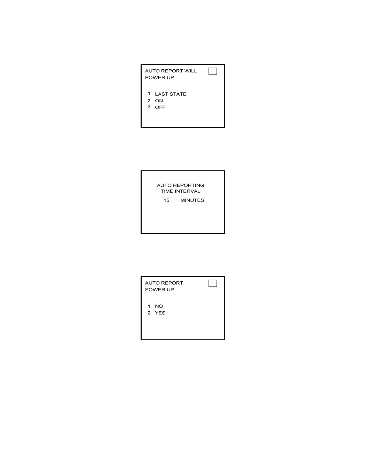
7. Insert the default for Auto Report and press ENTER. See Figure 4-5.
Figure 4-5
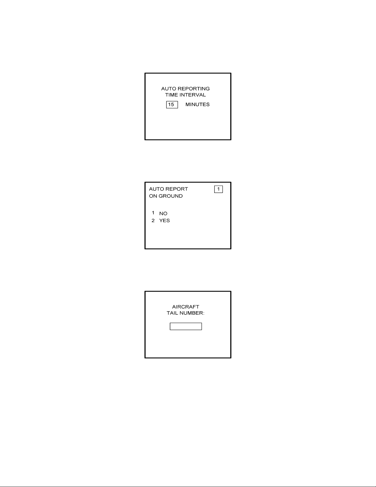
8. Insert 15 as the Auto Reporting time interval unless advised differently by the
pilot/operator and press ENTER. See Figure 4-6.
Figure 4-6
IMAFISJWA 4-5
March/2001
Page 5

Global
AIRBORNE FLIGHT INFORMATION SYSTEM
9. This step is applicable only to DMU P/N 42000-03-03 and 42000-04-03. Select Option
1 if reports are not wanted on the ground. Select Option 2 if reports on the ground are
required. See Figure 4-7.
Figure 4-7
10. Insert complete aircraft registration number (tail number) in the cursor field and press
ENTER. See Figure 4-8.
Figure 4-8
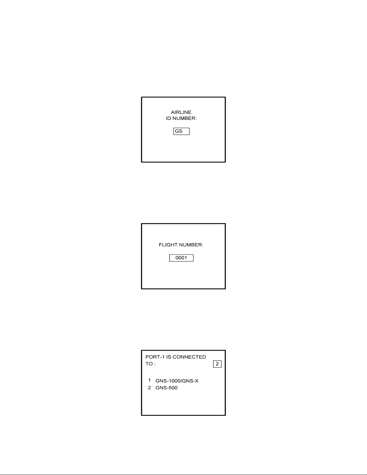
11. Insert GS as the Airline ID number and press ENTER. See Figure 4-9.
NOTE:
Currently, GS is the only valid entry and may change at a future time.
Figure 4-9
IMAFISJWA 4-6
March/2001
Page 6

Global
AIRBORNE FLIGHT INFORMATION SYSTEM
12. In the Flight Number cursor field, insert the number 0001 as shown in Figure 4-10.
Press ENTER.
NOTE:
Currently, 0001 is the only valid entry and may change at a future time.
Figure 4-10
13. This step is only applicable to DMU P/N 42000-01-01 and 42000-02-02. Determine the
number of NMUs connected to the DMU (there are a maximum of 3), insert the number
in the cursor field, and press ENTER. See Figure 4-11.
Figure 4-11
14. Complete this step for all other versions. Insert 2 as shown in Figure 4-12 to indicate
that Port 1 is connected to the GNS-500A system and press ENTER.
NOTE:
GNS-X applies also to GNS-X
ES, GNS-XL
and GNS-XLS.
Figure 4-12
IMAFISJWA 4-7
March/2001
Page 7
Global
AIRBORNE FLIGHT INFORMATION SYSTEM
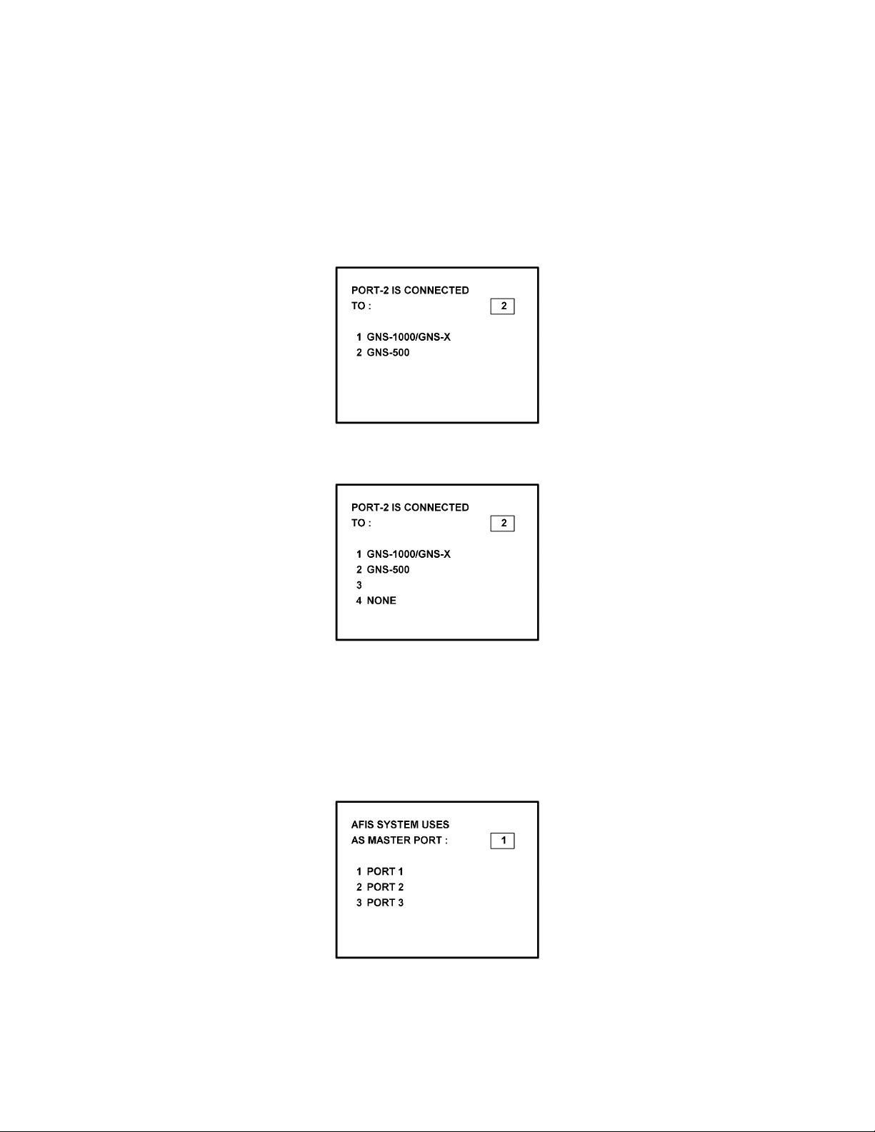
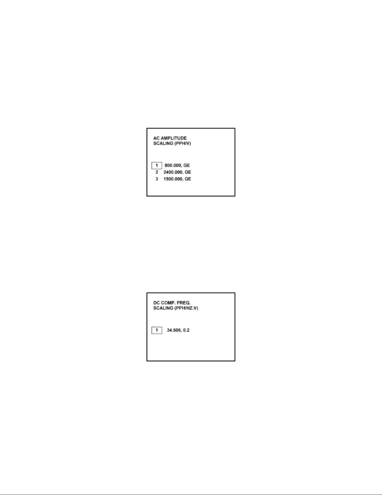
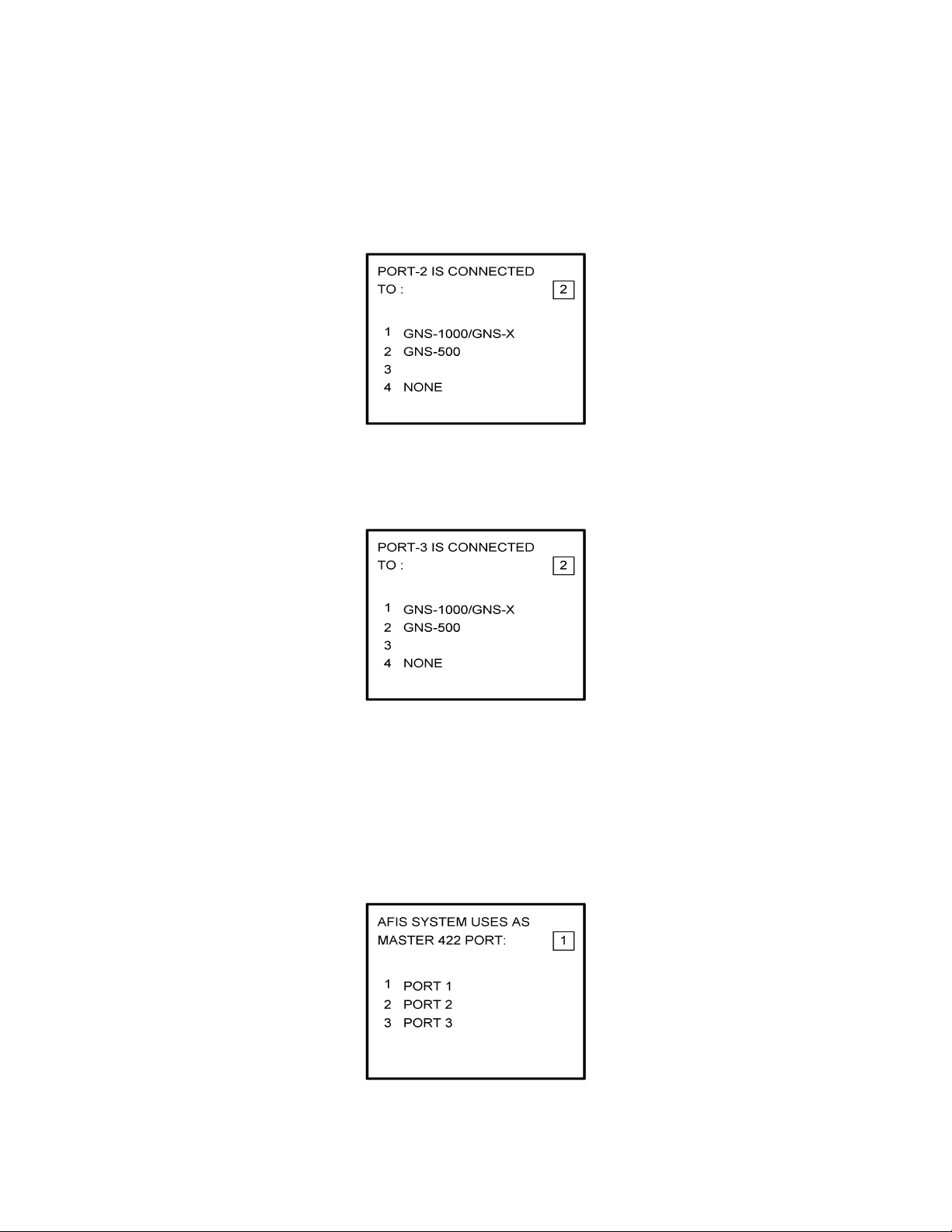
15. If applicable, insert 2 to designate that Port 2 is connected to the GNS-500A system.
Press ENTER. See Figure 4-13a for DMU P/N 42000-01-01 and 42000-02-02. See
Figure 4-13b for DMU P/N 42000-03-03 and 42000-04-03.
NOTE:
GNS-X applies also to GNS-X
Figure 4-13A
ES, GNS-XL
and GNS-XLS.
Figure 4-13B
NOTE:
Program for Port 3 as necessary. Press ENTER to continue.
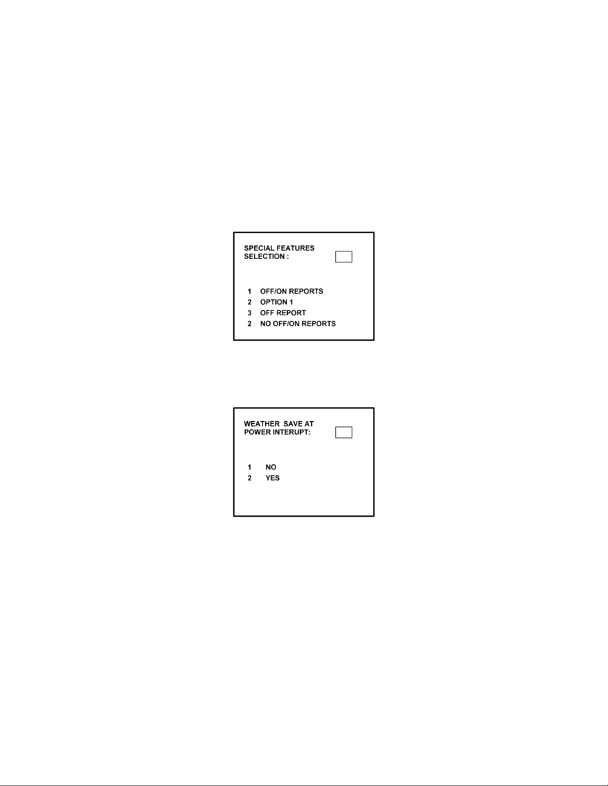
16. To designate Port 1 as the Master 422 Port, insert 1 and press ENTER. See Figure
4-14.
Figure 4-14
IMAFISJWA 4-8
March/2001
Page 8

Global
AIRBORNE FLIGHT INFORMATION SYSTEM
NOTE
The master port refers to the use of one port by the software to have priority
over the data from other ports (i.e. CDU2). Global recommends use of Port
1.
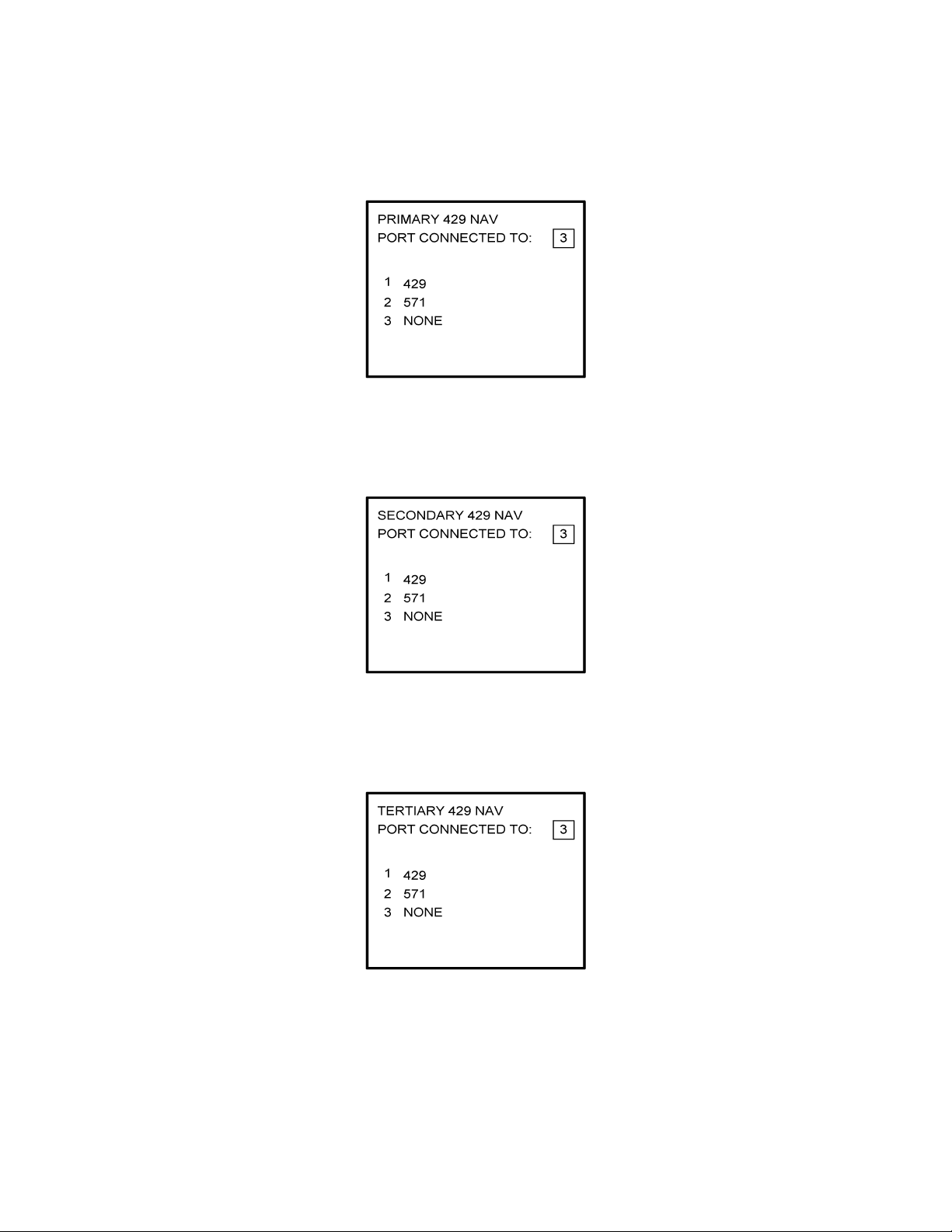
17. The 429 port option is not applicable to DMU P/N 42000-XX-XX. This page will only
appear if DMU P/N 42000-03-03 or 42000-04-03 is installed. If applicable, insert 3 and
press ENTER. See Figure 4-15.
Figure 4-15
18. The 429 port option is not applicable to DMU P/N 42000-XX-XX. This page will only
appear if DMU P/N 42000-03-03 or 42000-04-03 is installed. If applicable, insert 3 and
press ENTER. See Figure 4-16.
Figure 4-16
19. The 429 port option is not applicable to DMU P/N 42000-XX-XX. This page will only
appear if DMU P/N 42000-03-03 or 42000-04-03 is installed. If applicable, insert 3 and
press ENTER. See Figure 4-17.
Figure 4-17
IMAFISJWA 4-9
March/2001
Page 9

Global
AIRBORNE FLIGHT INFORMATION SYSTEM
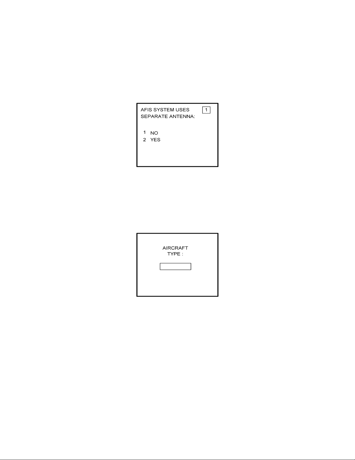
20. Select whether the AFIS system is using a separate antenna and press ENTER. See
Figure 4-18.
NOTE:
The Antenna Switching Unit (ASU) allows the AFIS system to share an
antenna with the VHF Com or use its own antenna.
Figure 4-18
21. Insert type designator as listed in Table 4-1 and press ENTER. See Figure 4-19.
NOTE:
If the aircraft type is not listed in Table 4-1, contact Global Data Center to
obtain type designator.
Figure 4-19
IMAFISJWA 4-10
March/2001
Page 10

Global
AIRBORNE FLIGHT INFORMATION SYSTEM
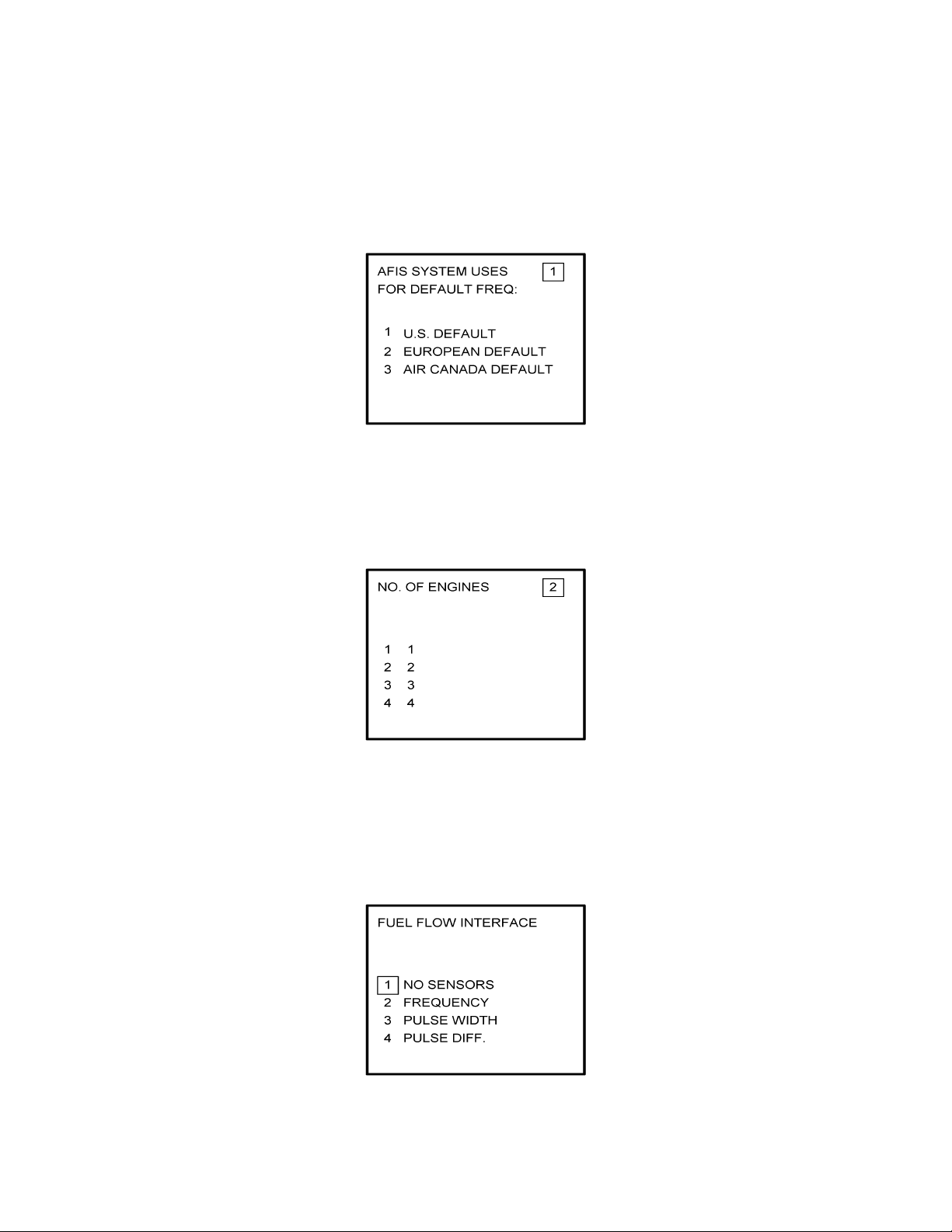
22. Select Option 1 for ARINC network, Option 2 for SITA or AVICOM network. Press
ENTER to continue. See Figure 4-20.
NOTE:
Air Canada network is no longer active.
Figure 4-20
23. Steps 23 and 24 are only applicable to Series 4/5 users with Fuel Flow option DMU
P/N 42000-02-02 or 42000-04-03. If other versions of the DMU are used, proceed to
Step 25. If applicable, select the number that corresponds to the number of engines on
the aircraft and press the ENTER Key. See Figure 4-21.
Figure 4-21
24. Fuel Flow Interface - Enter one of seven options. See Figure 4-22.
Using the Up and Down arrow keys, move the fuel flow sensor options into the
stationary cursor field. Scroll through and press the ENTER Key to select the desired
option.
Figure 4-22 (page 1)
IMAFISJWA 4-11
March/2001
Page 11

Global
AIRBORNE FLIGHT INFORMATION SYSTEM
Figure 4-22 (PAGE 2)
(a) If Option 1 (NO SENSORS) is selected, the system will go to Step 25.
(b) If Option 2 (FREQUENCY) is selected, Figure 4-23 appears. Select the appropriate
manufacturer and scaling by using the Up and Down arrow keys to place the desired
option in the cursor field. Press ENTER.
NOTE:
See Section 1 to cross-reference the manufacturer part number to the fuel
flow type and frequency scaling. LEAR stands for J.E.T. fuel flow
manufacturer and AERO is AERO Systems.
Figure 4-23 (PAGE 1)
Figure 4-23 (PAGE 2)
IMAFISJWA 4-12
March/2001
Page 12

Global
AIRBORNE FLIGHT INFORMATION SYSTEM
(c) If Option 3 (PULSE WIDTH) is selected, Figure 4-24 is displayed. Use the Up and
Down arrow keys to place the appropriate manufacturer/scaling in the cursor field.
Press ENTER.
NOTE:
See Section 1.3.2, SYSTEM SPECIFICATIONS, to cross-reference the
fuel flow indicator/transmitter manufacturer’s part number to the
appropriate scaling values. ELD stands for ELDEC. See Figure 4-24.
Figure 4-24 (PAGE 1)
Figure 4-24 (PAGE 2)
(d) If Option 4 (PULSE DIFF) is selected, Figure 4-25 is displayed. Use the Up and Down
arrow keys to place the appropriate manufacturer/scaling in the cursor field. Press
ENTER.
NOTE:
See Section 1.3.2, SYSTEM SPECIFICATIONS, to cross-reference the
fuel flow indicator/transmitter manufacturer’s part number to the
appropriate scaling values.
Figure 4-25
IMAFISJWA 4-13
March/2001
Page 13

Global
AIRBORNE FLIGHT INFORMATION SYSTEM
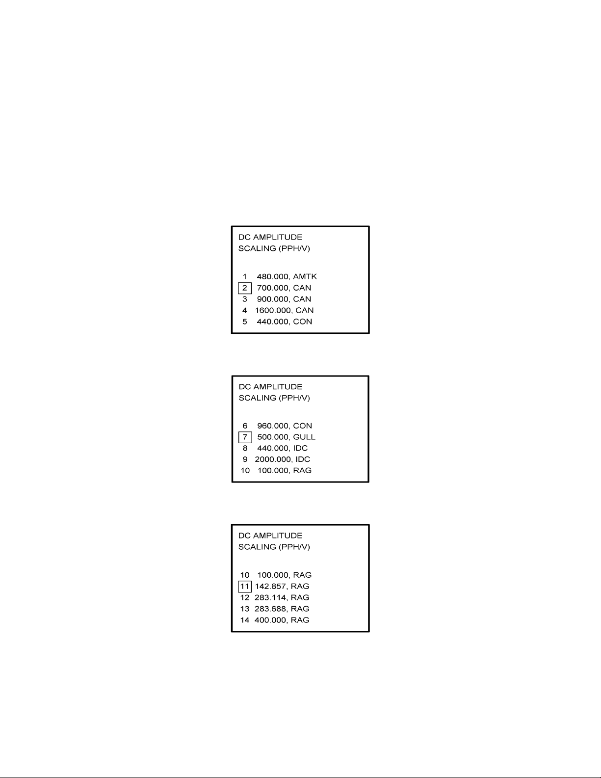
(e) If Option 5 (DC AMPLITUDE) is selected, Figure 4-26 is displayed. Use the Up and
Down arrow keys to place the appropriate manufacturer/scaling in the cursor field.
Press ENTER.
NOTE:
See Section 1.3.2, SYSTEM SPECIFICATIONS, to cross-reference the
fuel flow indicator/transmitter manufacturer’s part number to the
appropriate scaling values. AMTK stands for AMETEK. CAN is Canadian
Marconi, CON is Consolidated Airborne and RAG is Ragen Data System
Figure 4-26 (PAGE 1)
Figure 4-26 (PAGE 2)
Figure 4-26 (PAGE 3)
IMAFISJWA 4-14
March/2001
Page 14
Global
AIRBORNE FLIGHT INFORMATION SYSTEM
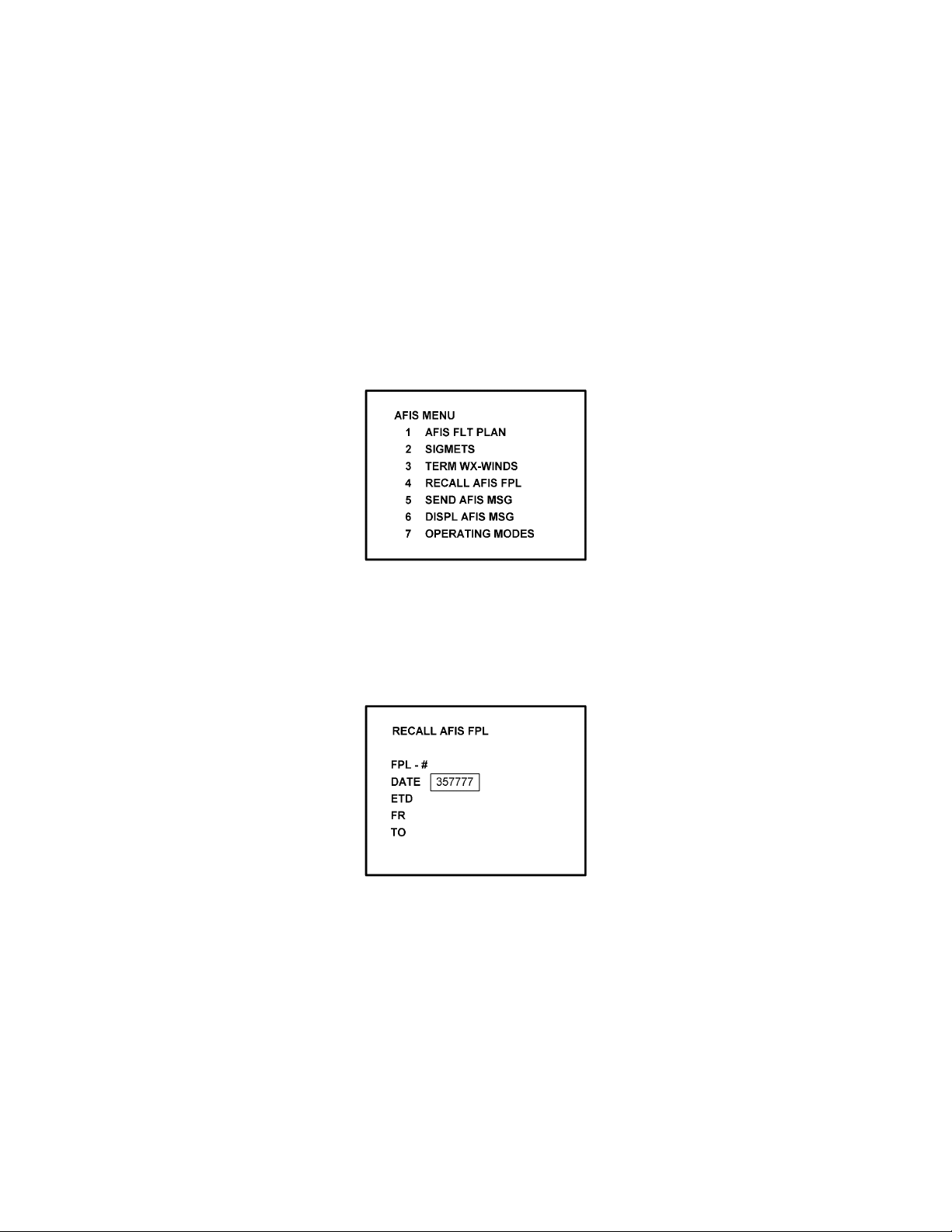
(f) If Option 6 (AC AMPLITUDE) is selected, Figure 4-27 is displayed. Use the Up and
Down arrow keys to place the appropriate manufacturer/scaling in the cursor field.
Press ENTER.
NOTE:
See Section 1.3.2, SYSTEM SPECIFICATIONS, to cross-reference the
fuel flow indicator/transmitter manufacturer’s part number to the
appropriate scaling values. GE stands for General Electric.
Figure 4-27
(g) If Option 7 (DC COMP. FREQ.) is selected, Figure 4-28 is displayed. Use the Up and
Down arrow keys to place the appropriate manufacturer/scaling in the cursor field.
Press ENTER.
NOTE:
See Section 1.3.2, SYSTEM SPECIFICATIONS, to cross-reference the
fuel flow indicator/transmitter manufacturer’s part number to the
appropriate scaling values.
Figure 4-28
IMAFISJWA 4-15
March/2001
Page 15
Global
AIRBORNE FLIGHT INFORMATION SYSTEM
25. This step is only applicable to DMU P/N 42000-03-03 and 42000-04-03. If other
versions of DMU are used, proceed to Step 26.
Select the applicable special feature option and press the ENTER Key to continue. See
Figure 4-29.
NOTE:
OFF/ON REPORTS = logging takeoff and landing times. OPTION 1 =
customer defined non-standard AFIS features. OFF REPORT = logging
takeoff times. NO OFF/ON REPORTS = no logging of takeoff and landing
times.
Figure 4-29
26. Select whether stored weather will be retained in memory when power is interrupted.
Press the ENTER Key to continue. See Figure 4-30.
Figure 4-30
IMAFISJWA 4-16
March/2001
Page 16

Global
AIRBORNE FLIGHT INFORMATION SYSTEM
27. This step is only applicable to DMU P/N 42000-03-03 and 42000-04-03. If other
versions of the DMU are used, proceed to Step 30.
Select the desired option for Auto Weather update status at power up and press the
ENTER Key. See Figure 4-31.
Figure 4-31
28. This step is only applicable to Series 4/5 users with Satellite Data Communication
System option DMU P/N 42000-03-03 and 42000-04-03. If other versions of the DMU
are used, proceed to Step 30.
If applicable, select Satcom Option 2 and press the ENTER Key. See Figure 4-32.
If Option 1 is selected, proceed to Step 30. Option 3 (ARINC 741) and Option 4
(SATFONE) are not available for DMU P/N 42000-03-03 and 42000-04-03. These
options apply to other FMS/DMU configurations discussed elsewhere.
Figure 4-32
IMAFISJWA 4-17
March/2001
Page 17

Global
AIRBORNE FLIGHT INFORMATION SYSTEM
29. This step is only applicable to Series 4/5 users with Satellite Data Communication
System option DMU P/N 42000-03-03 and 42000-04-03. Also, Option 2 must have
been selected in Step 28. If other versions of the DMU are used or Option 1 was
selected in the previous step, proceed to Step 30. Select the desired option and press
the ENTER Key. See Figure 4-33.
Figure 4-33
30. Write configuration data to the Configuration Module by selecting 2 and press the
ENTER Key. See Figure 4-34.
Figure 4-34
IMAFISJWA 4-18
March/2001
Page 18
Global
AIRBORNE FLIGHT INFORMATION SYSTEM
4.2 CONFIGURATION MODULE PROGRAMMING FOR GNS-500A SERIES 4/5 WITH DMU
P/N 400-045500-XXXX.
NOTE:
The following configuration pages are not available for DMU P/N
400-045500-0210 or 400-045500-2010.
1. Install test connector P/N 12870-1 to the front of the DMU on J102.
2. Turn system on. Press the ENTER Key to accept DATE, GMT, and Position.
3. Press the DATA Key to display the AFIS MENU Page. See Figure 4-35.
Figure 4-35
4. Use the UP or DOWN Arrow Key to position the cursor over Option 4, RECALL AFIS
FPL and press the ENTER Key. The RECALL AFIS FPL Page appears. Use the UP or
DOWN Arrow Key to position the cursor over the DATE field and enter 357777. Press
the ENTER Key. See Figure 4-36.
Figure 4-36
IMAFISJWA 4-19
March/2001
Page 19

Global
AIRBORNE FLIGHT INFORMATION SYSTEM
5. Select the AFIS configuration to be read or modified from the AFIS Configuration Menu
Page (Figure 4-37) and press the ENTER Key.
The dates of previously entered configurations are shown in Options 1 to 3. The
newest configuration date appears first. Option 4 allows for the entry of a new
configuration. Select Options 1 to 4 as desired and Figure 4-38 will be displayed.
Figure 4-37
6. Insert the basic operating weight and press ENTER. See Figure 4-38.
Figure 4-38
7. Insert the default for Auto Report and press ENTER. See Figure 4-39.
Figure 4-39
IMAFISJWA 4-20
March/2001
Page 20
Global
AIRBORNE FLIGHT INFORMATION SYSTEM
8. Insert 15 as the Auto Reporting time interval unless advised differently by the
pilot/operator and press ENTER. See Figure 4-40.
Figure 4-40
9. Select Option 1 if reports are not wanted on the ground. Select Option 2 if reports on
the ground are required. See Figure 4-41.
Figure 4-41
10. Insert complete aircraft registration number (tail number) in the cursor field and press
ENTER. See Figure 4-42.
Figure 4-42
IMAFISJWA 4-21
March/2001
Page 21
Global
AIRBORNE FLIGHT INFORMATION SYSTEM
11. Insert GS as the Airline ID number and press ENTER. See Figure 4-43.
NOTE:
Currently, GS is the only valid entry and may change at a future time.
Figure 4-43
12. In the Flight Number cursor field, insert the number 0001 as shown in Figure 4-44.
Press ENTER.
NOTE:
Currently, 0001 is the only valid entry and may change at a future time.
Figure 4-44
13. Insert 2 as shown in Figure 4-45 to indicate that Port 1 is connected to the GNS-500A
system and press ENTER.
NOTE:
GNS-X applies also to GNS-X
GNS-XL and GNS-XLS.
ES,
Figure 4-45
IMAFISJWA 4-22
March/2001
Page 22
Global
AIRBORNE FLIGHT INFORMATION SYSTEM
14. If applicable, insert 2 to designate that Port 2 is connected to the GNS-500A system.
Press ENTER. See Figure 4-46.
NOTE:
GNS-X applies also to GNS-X
GNS-XL and GNS-XLS.
ES,
Figure 4-46
15. If applicable, insert 2 to designate that Port 3 of connected to the GNS-500A system
and press ENTER. See Figure 4-47.
Figure 4-47
16. To designate Port 1 as the Master 422 Port, insert 1 and press ENTER. See Figure
4-48.
NOTE:
The master port refers to the use of one port by the software to have
priority over the data from other ports (i.e. CDU2). Honeywell
recommends use of Port 1.
Figure 4-48
IMAFISJWA 4-23
March/2001
Page 23
Global
AIRBORNE FLIGHT INFORMATION SYSTEM
17. The 429 port option is only applicable when other manufacturer’s navigation systems
are installed. If only GWS systems are used, insert 3 and press ENTER. See Figure
4-49.
Figure 4-49
18. The 429 port option is only applicable when other manufacturer’s navigation systems
are installed. If only Global systems are used, insert 3 and press ENTER. See Figure
4-50.
Figure 4-50
19. The 429 port option is only applicable when other manufacturer’s navigation systems
are installed. If only GWS systems are used, insert 3 and press ENTER. See Figure
4-51.
Figure 4-51
IMAFISJWA 4-24
March/2001
Page 24
Global
AIRBORNE FLIGHT INFORMATION SYSTEM
20. Select whether the AFIS system is using a separate antenna and press ENTER. See
Figure 4-52.
NOTE:
The Antenna Switching Unit (ASU) allows the AFIS system to share an
antenna with the VHF Comm or use its own antenna.
Figure 4-52
21. Insert type designator as listed in Table 4-1 and press ENTER. See Figure 4-53.
NOTE:
If the aircraft type is not listed in Table 4-1, contact Global Data
Center to obtain type designator.
Figure 4-53
IMAFISJWA 4-25
March/2001
Page 25
Global
AIRBORNE FLIGHT INFORMATION SYSTEM
22. Select Option 1 for ARINC network, Option 2 for SITA or AVICOM network. Press
ENTER to continue. See Figure 4-54.
NOTE:
Air Canada network is no longer active.
Figure 4-54
23. Steps 23 and 24 are only applicable to Series 4/5 users with Fuel Flow option DMU
P/N 400-045500-0002, 400-045500-0004 or 400-045500-0006. If other versions of the
DMU are used, proceed to Step 25. If applicable, select the number that corresponds
to the number of engines on the aircraft and press the ENTER Key. See Figure 4-55.
Figure 4-55
24. Fuel Flow Interface - Enter one of seven options. See Figure 4-56.
Using the Up and Down arrow keys, move the fuel flow sensor options into the
stationary cursor field. Scroll through and press the ENTER Key to select the desired
option.
Figure 4-56 (PAGE 1)
IMAFISJWA 4-26
March/2001
Page 26

Global
AIRBORNE FLIGHT INFORMATION SYSTEM
Figure 4-56 (PAGE 2)
(a) If Option 1 (NO SENSORS) is selected, the system will go to Step 25.
(b) If Option 2 (FREQUENCY) is selected, Figure 4-57 appears. Select the appropriate
manufacturer and scaling by using the Up and Down arrow keys to place the desired
option in the cursor field. Press ENTER.
NOTE:
See Section 1.3.2, SYSTEM SPECIFICATIONS, to cross-reference the
manufacturer part number to the fuel flow type and frequency scaling.
LEAR stands for J.E.T. fuel flow manufacturer and AERO is AERO
Systems.
Figure 4-57 (PAGE 1)
Figure 4-57 (PAGE 2)
IMAFISJWA 4-27
March/2001
Page 27

Global
AIRBORNE FLIGHT INFORMATION SYSTEM
(c) If Option 3 (PULSE WIDTH) is selected, Figure 4-58 is displayed. Use the Up and
Down arrow keys to place the appropriate manufacturer/scaling in the cursor field.
Press ENTER.
NOTE:
See Section 1.3.2, SYSTEM SPECIFICATIONS, to cross-reference the
fuel flow indicator/transmitter manufacturer’s part number to the
appropriate scaling values. ELD stands for ELDEC. See Figure 4-58.
Figure 4-58 (PAGE 1)
Figure 4-58 (PAGE 2)
(d) If Option 4 (PULSE DIFF) is selected, Figure 4-59 is displayed. Use the Up and Down
arrow keys to place the appropriate manufacturer/scaling in the cursor field. Press
ENTER.
NOTE:
See Section 1.3.2, SYSTEM SPECIFICATIONS, to cross-reference the
fuel flow indicator/transmitter manufacturer’s part number to the
appropriate scaling values.
Figure 4-59
IMAFISJWA 4-28
March/2001
Page 28
Global
AIRBORNE FLIGHT INFORMATION SYSTEM
(e) If Option 5 (DC AMPLITUDE) is selected, Figure 4-60 is displayed. Use the Up and
Down arrow keys to place the appropriate manufacturer/scaling in the cursor field.
Press ENTER.
NOTE:
See Section 1.3.2, SYSTEM SPECIFICATIONS, to cross-reference the
fuel flow indicator/transmitter manufacturer’s part number to the
appropriate scaling values. AMTK stands for AMETEK. CAN is Canadian
Marconi, CON is Consolidated Airborne and RAG is Ragen Data System.
Figure 4-60 (PAGE 1)
Figure 4-60 (PAGE 2)
Figure 4-60 (PAGE 3)
IMAFISJWA 4-29
March/2001
Page 29

Global
AIRBORNE FLIGHT INFORMATION SYSTEM
(f) If Option 6 (AC AMPLITUDE) is selected, Figure 4-61 is displayed. Use the Up and
Down arrow keys to place the appropriate manufacturer/scaling in the cursor field.
Press ENTER.
NOTE:
See Section 1.3.2, SYSTEM SPECIFICATIONS, to cross-reference the
fuel flow indicator/transmitter manufacturer’s part number to the
appropriate scaling values. GE stands for General Electric.
Figure 4-61
(g) If Option 7 (DC COMP. FREQ.) is selected, Figure 4-62 is displayed. Use the Up and
Down arrow keys to place the appropriate manufacturer/scaling in the cursor field.
Press ENTER.
NOTE:
See Section 1.3.2, SYSTEM SPECIFICATIONS, to cross-reference the
fuel flow indicator/transmitter manufacturer’s part number to the
appropriate scaling values.
Figure 4-62
IMAFISJWA 4-30
March/2001
Page 30

Global
AIRBORNE FLIGHT INFORMATION SYSTEM
25. Select the applicable special feature option and press the ENTER Key to continue.
See Figure 4-63.
NOTE:
OFF/ON REPORTS = logging takeoff and landing times. OPTION 1 =
customer defined non-standard AFIS features. OFF REPORT = logging
takeoff times. NO OFF/ON REPORTS = no logging of takeoff and landing
times.
Figure 4-63
26. Select whether stored flight plans, messages and weather will be retained in memory
when power is interrupted. Press the ENTER Key to continue. See Figure 4-64.
Figure 4-64
27. Select the desired option for Auto Weather update status at power up and press the
ENTER Key. See Figure 4-65.
Figure 4-65
IMAFISJWA 4-31
March/2001
Page 31

Global
AIRBORNE FLIGHT INFORMATION SYSTEM
28. This step is only applicable to Series 4/5 users with Satellite Data Communication
System option DMU P/N 400-045500-0003, 400-045500-0004, 400-045500-0005 or
400-045500-0006. If other versions of the DMU are used, proceed to Step 30.
If applicable, select Satcom Option 2 and press the ENTER Key. See Figure 4-66.
If Option 1 is selected, proceed to Step 30. Options 3 and 4 are only available with
DMU P/N 400-045500-0005 or 400-045500-0006.
Figure 4-66
29. Select the desired option and press the ENTER Key. See Figure 4-67.
Figure 4-67
30. Write configuration data to the Configuration Module by selecting 2 and press the
ENTER Key. See Figure 4-68.
Figure 4-68
IMAFISJWA 4-32
March/2001
Page 32

Global
AIRBORNE FLIGHT INFORMATION SYSTEM
4.3 CONFIGURATION MODULE PROGRAMMING FOR GNS-1000, GNS-X, GNS-X
GNS-XL OR GNS-XLS WITH DMU P/N 42000-01-01 OR 42000-03-03
1. Install test connector P/N 12870-1 to the front of the DMU on J102.
2. Turn system on. Press the ENTER Key to accept DATE, GMT, and Position.
3. Press the PLAN Key or AFIS Key to display the AFIS MENU Page. See Figure 4-69 or
Figure 4-70.
Figure 4-69
ES,
Figure 4-70
4. Use the UP or DOWN Arrow Key to position the cursor over the RECALL AFIS FPL
option and press the ENTER Key. The RECALL AFIS FPL Page appears. Use the UP
or DOWN Arrow Key to position the cursor over the DATE field and enter 357777.
Press the ENTER Key. See Figure 4-71.
Figure 4-71
IMAFISJWA 4-33
March/2001
Page 33

Global
AIRBORNE FLIGHT INFORMATION SYSTEM
5. Select the AFIS configuration to be read or modified from the AFIS Configuration Menu
Page (Figure 4-69) and press the ENTER Key.
The dates of previously entered configurations are shown in Options 1 to 3. The
newest configuration date appears first. Option 4 allows for the entry of a new
configuration. Select Options 1 to 4 as desired and Figure 4-72 will be displayed.
Figure 4-72
6. Insert the basic operating weight and press ENTER. See Figure 4-73.
Figure 4-73
7. Insert the default for Auto Report and press ENTER. See Figure 4-74.
Figure 4-74
IMAFISJWA 4-34
March/2001
Page 34

Global
AIRBORNE FLIGHT INFORMATION SYSTEM
8. Insert 15 as the Auto Reporting time interval unless advised differently by the
pilot/operator and press ENTER. See Figure 4-75.
Figure 4-75
9. Select Option 1 if reports are not wanted on the ground. Select Option 2 if reports on
the ground are required. See Figure 4-76.
Figure 4-76
10. Insert complete aircraft registration number (tail number) in the cursor field and press
ENTER. See Figure 4-77.
Figure 4-77
IMAFISJWA 4-35
March/2001
Page 35

Global
AIRBORNE FLIGHT INFORMATION SYSTEM
11. Insert GS as the Airline ID number and press ENTER. See Figure 4-78.
NOTE:
Currently, GS is the only valid entry and may change at a future time.
Figure 4-78
12. In the Flight Number cursor field, insert the number 0001 as shown in Figure 4-79.
Press ENTER.
NOTE:
Currently, 0001 is the only valid entry and may change at a future time.
Figure 4-79
13. This step is only applicable to DMU P/N 42000-01-01. Determine the number of CDUs
or NMUs connected to the DMU (there are a maximum of 3), insert the number in the
cursor field, and press ENTER. See Figure 4-80.
Figure 4-80
IMAFISJWA 4-36
March/2001
Page 36

Global
AIRBORNE FLIGHT INFORMATION SYSTEM
14. Insert 1 as shown in Figure 4-81 to indicate that Port 1 is connected to the GNS-1000
or GNS-X system and press ENTER.
NOTE:
GNS-X applies also to GNS-X
GNS-XL and GNS-XLS.
ES,
Figure 4-81
15. If applicable, insert 1 to designate that Port 2 is connected to the GNS-1000 or GNS-X
system. Press ENTER. See Figure 4-82a for DMU P/N 42000-01-01. See Figure 4-82b
for DMU P/N 42000-03-03.
NOTE:
GNS-X applies also to GNS-X
GNS-XL and GNS-XLS.
ES,
Figure 4-82A
Figure 4-82B
IMAFISJWA 4-37
March/2001
Page 37

Global
AIRBORNE FLIGHT INFORMATION SYSTEM
16. If applicable, insert 1 to designate that Port 3 is connected to the GNS-1000 or GNS-X
system. Press ENTER. See Figure 4-83a for DMU P/N 42000-01-01. See Figure 4-83b
for DMU P/N 42000-03-03.
NOTE:
GNS-X applies also to GNS-X
Figure 4-83A
GNS-XL and GNS-XLS.
ES,
Figure 4-83B
17. To designate Port 1 as the Master 422 Port, insert 1 and press ENTER. See Figure
4-84.
NOTE:
The master port refers to the use of one port by the software to have priority
over the data from other ports (ie CDU2). Global recommends use of Port 1.
Figure 4-84
IMAFISJWA 4-38
March/2001
Page 38

Global
AIRBORNE FLIGHT INFORMATION SYSTEM
18. The 429 port option is not applicable to DMU P/N 42000-XX-XX. This page will only
appear if DMU P/N 42000-03-03 is installed. If applicable, insert 3 and press ENTER.
See Figure 4-85.
Figure 4-85
19. The 429 port option is not applicable to DMU P/N 42000-XX-XX. This page will only
appear if DMU P/N 42000-03-03 is installed. If applicable, insert 3 and press ENTER.
See Figure 4-86.
Figure 4-86
20. The 429 port option is not applicable to DMU P/N 42000-XX-XX. This page will only
appear if DMU P/N 42000-03-03 is installed. If applicable, insert 3 and press ENTER.
See Figure 4-87.
Figure 4-87
IMAFISJWA 4-39
March/2001
Page 39

Global
AIRBORNE FLIGHT INFORMATION SYSTEM
21. Select whether the AFIS system is using a separate antenna and press ENTER. See
Figure 4-88.
NOTE:
The Antenna Switching Unit (ASU) allows the AFIS system to share an
antenna with the VHF Comm or use its own antenna.
Figure 4-88
22. Insert type designator as listed in Table 4-1 and press ENTER. See Figure 4-89.
NOTE:
If the aircraft type is not listed in Table 4-1, contact Global Data Center to
obtain type designator.
Figure 4-89
23. Select Option 1 for ARINC network, Option 2 for SITA or AVICOM network, or Option
3 for Air Canada network. Press ENTER to continue. See Figure 4-90.
NOTE:
Air Canada network is no longer active.
Figure 4-90
IMAFISJWA 4-40
March/2001
Page 40

Global
AIRBORNE FLIGHT INFORMATION SYSTEM
24. Fuel Flow option is not available for GNS-1000, GNS-X, GNS-X
GNS-X
. Insert 1 and press the ENTER Key. See Figure 4-91.
LS
Figure 4-91
25. Fuel Flow option is not available for GNS-1000, GNS-X, GNS-X
GNS-X
. Select 1 and press the ENTER Key. See Figure 4-92.
LS
GNS-XL or
ES,
GNS-XL or
ES,
Figure 4-92
26. This step is only applicable to DMU P/N 42000-03-03. If other versions of DMU are
used, proceed to Step 27. Select the applicable special feature option and press the
ENTER Key to continue. See Figure 4-93.
NOTE:
OFF/ON REPORTS = logging takeoff and landing times. OPTION 1 =
customer defined non-standard AFIS features. OFF REPORT = logging
takeoff times. NO OFF/ON REPORTS = no logging of takeoff and landing
times.
Figure 4-93
IMAFISJWA 4-41
March/2001
Page 41

Global
AIRBORNE FLIGHT INFORMATION SYSTEM
27. Select whether stored weather will be retained in memory when power is interrupted.
Press the ENTER Key to continue. See Figure 4-94.
Figure 4-94
28. This step is only applicable to DMU P/N 42000-03-03. If other versions of the DMU are
used, proceed to Step 30. Select the desired option for Auto Weather update status at
power up and press the ENTER Key. See Figure 4-95.
Figure 4-95
29. This step is only applicable to GNS-1000, GNS-X, GNS-X
GNS-XL or GNS-XLS with
ES,
Satellite Data Communication System option DMU P/N 42000-03-03.
If applicable, select Satcom Option 2 and press the ENTER Key. See Figure 4-96. If
Option 1 is selected, proceed to Step 31. Option 3 (ARINC 741) and Option 4
(SATFONE) are not available for DMU P/N 42000-03-03. These options apply to other
FMS/DMU configurations discussed elsewhere.
Figure 4-96
IMAFISJWA 4-42
March/2001
Page 42

Global
AIRBORNE FLIGHT INFORMATION SYSTEM
30. This step is only applicable to GNS-1000, GNS-X, GNS-X
GNS-XL or GNS-XLS with
ES,
Satellite Data Communication System option DMU P/N 42000-03-03. If other versions
of the DMU are used, proceed to Step 31.
Select the desired option and press the ENTER Key. See Figure 4-97.
Figure 4-97
31. Write configuration data to the Configuration Module by selecting 2 and press the
ENTER Key. See Figure 4-98.
Figure 4-98
IMAFISJWA 4-43
March/2001
Page 43

Global
AIRBORNE FLIGHT INFORMATION SYSTEM
4.4 CONFIGURATION MODULE PROGRAMMING FOR GNS-1000, GNS-X, GNS-XES,
GNS-XL OR GNS-XLS WITH DMU P/N 400-045500-0001, 400-045500-0003 OR
400-045500-0005 AND OTHER FMS MANUFACTURES USING DMU P/N
400-045500-0001, 0002, -0003, -0004, -0005, -0006 OR -0130
1. Install test connector P/N 12870-1 to the front of the DMU on J102.
2. Turn system on. Press the ENTER Key to accept DATE, GMT, and Position.
(a) If DMU has been configured for ACARS proceed to step 4(a) otherwise step 3.
3. Press the PLAN Key or AFIS Key to display the AFIS MENU Page. See Figure 4-99 or
Figure 4-100.
Figure 4-99
Figure 4-100
IMAFISJWA 4-44
March/2001
Page 44

Global
AIRBORNE FLIGHT INFORMATION SYSTEM
4. Use the UP or DOWN Arrow Key or Line >Select keys to position the cursor over the
RECALL AFIS FPL option and press the ENTER Key. The RECALL AFIS FPL Page
appears. Use the UP or DOWN Arrow Key or Line Select keys to position the cursor
over the DATE field and enter 357777. Press the ENTER Key. See Figure 4-101.
Figure 4-101
NOTE:
ITEMS 4(a) through 4(k) are only available for -0003 or -0130. For other
part numbers skip to item 5.
(a) Press the PLAN key or AFIS key to display the ACARS page. See Figure 4-102 or
4-103.
Figure 4-102
Figure 4-103
IMAFISJWA 4-45
March/2001
Page 45

Global
AIRBORNE FLIGHT INFORMATION SYSTEM
(b) If ACARS page shown in Figure 4-102 appears, press “1" key and the PREFLIGHT
Data page, Figure 4-104 will appear. Otherwise proceed to step 4(h).
Figure 4-104
(c) Insert a one digit number (eg. 1) in FLT NO: field and press ENTER key. Cursor will
move FLT RLS DATE: field.
(d) Insert a one digit number (eg. 1) in FLT RLS DATE: field and press ENTER key.
Cursor will move to DEPT STN: field.
(e) Insert a three character departure station identifier (eg. MCI) in DEPT STN: field and
press ENTER key. Cursor will move to DEPT STN: field.
(f) Insert a three character destination station identifier (eg. MCI) in DEST STN: field
and press ENTER key. Cursor will move to ETE field.
(g) Enter 3577 in ETE field and press ENTER key. See Figure 4-105. Proceed to step 5.
Figure 4-105
(h) Insert a three digit number (eg. 111) in FLT# field and press ENTER key. Cursor will
move to DEPT field (see Figure 4-106).
(i) Insert a three character departure identifier (eg. MCI) in DEPT field and press
ENTER key. Cursor will move to DEST field.
(j) Insert a three character destination identifier (eg MCI) in DEST field and press
ENTER key. Cursor will move to ETD field.
IMAFISJWA 4-46
March/2001
Page 46

Global
AIRBORNE FLIGHT INFORMATION SYSTEM
(k) Enter 3577 in ETD field and press ENTER key. See Figure 4-106 and proceed to
step 5.
Figure 4-106
5. Select the AFIS configuration to be read or modified from the AFIS Configuration Menu
Page (Figure 4-107) and press the ENTER Key.
The dates of previously entered configurations are shown in Options 1 to 3. The
newest configuration date appears first. Option 4 allows for the entry of a new
configuration. Select Options 1 to 4 as desired and Figure 4-108 will be displayed.
Figure 4-107
6. Insert the basic operating weight and press ENTER. See Figure 4-108.
Figure 4-108
IMAFISJWA 4-47
March/2001
Page 47

Global
AIRBORNE FLIGHT INFORMATION SYSTEM
7. Insert the default for Auto Report and press ENTER. See Figure 4-109.
Figure 4-109
8. Insert 15 as the Auto Reporting time interval unless advised differently by the
pilot/operator and press ENTER. See Figure 4-110.
Figure 4-110
9. Select Option 1 if reports are not wanted on the ground. Select Option 2 if reports on
the ground are required. See Figure 4-111.
Figure 4-111
IMAFISJWA 4-48
March/2001
Page 48

Global
AIRBORNE FLIGHT INFORMATION SYSTEM
10. Insert complete aircraft registration number (tail number) in the cursor field and press
ENTER. See Figure 4-112.
Figure 4-112
11. Insert GS as the Airline ID number and press ENTER. See Figure 4-113.
NOTE:
Currently, GS is the only valid entry except for the following: XJ for
MESABA Airlines, DH for Atlantic Coast Aviation, Part Numbers
400-045500-0003 or 400-045500-0130 ONLY.
Figure 4-113
12. In the Flight Number cursor field, insert the number 0001 as shown in Figure 4-114.
Press ENTER.
NOTE:
Currently, 0001 is the only valid entry and may change at a future time.
Figure 4-114
IMAFISJWA 4-49
March/2001
Page 49

Global
AIRBORNE FLIGHT INFORMATION SYSTEM
13. Insert 1 as shown in Figure 4-115 to indicate that Port 1 is connected to the GNS-1000,
GNS-X, or other manufactures navigation system and press ENTER.
NOTE:
GNS-X applies also to GNS-X
GNS-XL and GNS-XLS.
ES,
Figure 4-115
14. If applicable, insert 1 to designate that Port 2 is connected to the GNS-1000 or GNS-X
system. Press ENTER. If no Global systems are connected, select Option 4. See
Figure 4-116.
NOTE:
GNS-X applies also to GNS-X
GNS-XL and GNS-XLS.
ES,
Figure 4-116
IMAFISJWA 4-50
March/2001
Page 50

Global
AIRBORNE FLIGHT INFORMATION SYSTEM
15. If applicable, insert 1 to designate that Port 3 is connected to the GNS-1000 or GNS-X
system. Press ENTER. If no Global systems are connected, select Option 4. See
Figure 4-117.
NOTE:
GNS-X applies also to GNS-X
GNS-XL and GNS-XLS.
ES,
Figure 4-117
16. To designate Port 1 as the Master 422 Port, insert 1 and press ENTER. See Figure
4-118.
NOTE:
The master port refers to the use of one port by the software to have priority
over the data from other ports (i.e. CDU2). Honeywell recommends use of
Port 1.
Figure 4-118
17. The 429 port option is only applicable when other manufacturer’s navigation systems
are installed. If only Global systems are used, insert 3 and press ENTER. See Figure
4-119.
Figure 4-119
IMAFISJWA 4-51
March/2001
Page 51

Global
AIRBORNE FLIGHT INFORMATION SYSTEM
18. The 429 port option is only applicable when other manufacturer’s navigation systems
are installed. If only Global systems are used, insert 3 and press ENTER. See Figure
4-120.
Figure 4-120
19. The 429 port option is only applicable when other manufacturer’s navigation systems
are installed. If only Global systems are used, insert 3 and press ENTER. See Figure
4-121.
Figure 4-121
20. Select whether the AFIS system is using a separate antenna and press ENTER. See
Figure 4-122.
NOTE:
The Antenna Switching Unit (ASU) allows the AFIS system to share an
antenna with the VHF Comm or use its own antenna.
Figure 4-122
IMAFISJWA 4-52
March/2001
Page 52

Global
AIRBORNE FLIGHT INFORMATION SYSTEM
21. Insert type designator as listed in Table 4-1 and press ENTER. See Figure 4-123.
NOTE:
If the aircraft type is not listed in Table 4-1, contact Global Data Center to
obtain type designator.
Figure 4-123
22. Select Option 1 for ARINC network or Option 2 for SITA or AVICOM network. Press
ENTER to continue. See Figure 4-124.
Figure 4-124
23. Fuel Flow option is not available for GNS-1000, GNS-X, GNS-X
GNS-X
. Insert 1 and press the ENTER Key. See Figure 4-125. If DMU P/N
LS
GNS-XL or
ES,
400-045500-0004, 400-045500-0006 or other NAV system is used, select the
appropriate fuel flow pages.
Figure 4-125
IMAFISJWA 4-53
March/2001
Page 53

Global
AIRBORNE FLIGHT INFORMATION SYSTEM
24. Fuel Flow option is not available for GNS-1000, GNS-X, GNS-X
GNS-X
. Select 1 and press the ENTER Key. See Figure 4-126.
LS
GNS-XL or
ES,
Figure 4-126
25. Select the applicable special feature option and press the ENTER Key to continue.
(a) If Airline ID of GS has been entered the special selection features page will appear
as in Figure 4-127.
NOTE:
OFF/ON REPORTS = logging takeoff and landing times. OPTION 1 =
customer defined non-standard AFIS features. OFF REPORT = logging
takeoff times. NO OFF/ON REPORTS = no logging of takeoff and landing
times.
Figure 4-127
IMAFISJWA 4-54
March/2001
Page 54

Global
AIRBORNE FLIGHT INFORMATION SYSTEM
(b) If Airline ID XJ or DH has been inserted the special feature option will be displayed as
Figure 4-128.
NOTE:
OFF/ON REPORTS = logging takeoff and landing times. OPTION 1 =
customer defined non-standard AFIS features. OFF REPORT = logging
takeoff times. NO OFF/ON REPORTS = no logging of takeoff and landing
times. ACARS REPORTS = Customer defined non-standard AFIS
features.
Figure 4-128
NOTE:
If Airline ID is GS, ACARS reports can be accessed by pressing *A or *M
and then pressing ENTER key.
If ACARS REPORTS, 5, has been selected see Figure 4-129 otherwise
proceed to step 27.
(c) If Airline ID of DH or *A has been entered, the following page selections will be
available.
Figure 4-129
IMAFISJWA 4-55
March/2001
Page 55

Global
AIRBORNE FLIGHT INFORMATION SYSTEM
Use UP or DOWN arrow keys or right hand line select keys to position cursor over
selections. Depress BACK key to cycle between YES and No selection. Press
ENTER key to select. Cursor will move to next entry below selection. If cursor is on
TITLE PAGE ACARS selection, then pressing ENTER key will activate the page
shown in Figure 4-130.
BACK key - depressed with cursor off page causes SPECIAL FEATURES selection
to appear. ENTER key - depressed with cursor off page causes screen shown in
Figure 4-130 to appear.
Figure 4-130
Use UP or Down arrow or right hand LINE SELECT keys to position cursor over
option.
BACK key - depressed to cycle between YES and NO with cursor over desired
selection. ENTER key - depress to select. Cursor will move to next entry below
selection. If over USE DMU WT-ON-WHEELS INPUT selection, pressing ENTER
key will proceed to step 27.
(d) If Airline ID of XJ or *M has been entered, the following configuration selection will
be available. See Figure 4-131.
Figure 4-131
Use UP or Down arrow or right hand LINE SELECT keys to position cursor over
selections.
BACK key - depressed to cycle between YES and NO with cursor over desired
selection.
IMAFISJWA 4-56
March/2001
Page 56

Global
AIRBORNE FLIGHT INFORMATION SYSTEM
ENTER key - depress to select. Cursor will move to next entry below selection. If over
TITLE PAGE ACARS selection, pressing ENTER key will display the page shown in
Figure 4-130.
26. Select whether stored flight plans, messages and weather will be retained in memory
when power is interrupted. Press the ENTER Key to continue. See Figure 4-132.
Figure 4-132
27. Select the desired option for Auto Weather update status at power up and press the
ENTER Key. See Figure 4-133.
Figure 4-133
IMAFISJWA 4-57
March/2001
Page 57

Global
AIRBORNE FLIGHT INFORMATION SYSTEM
28. This step is only applicable to GNS-1000, GNS-X, GNS-X
GNS-XL or GNS-XLS with
ES,
Satellite Data Communication System option DMU P/N 400-045500-0003,
400-045500-0004, 400-045500-0005, 400-045500-0006 or 400-045500-0130.
If other versions of the DMU are used, proceed to Step 30. If applicable, select Satcom
Option 2 and press the ENTER Key. See Figure 4-134.
Select GWS option for AERO-C satellite system, ARINC 741 for Aeronautical Standard
(ARINC 741) satellite system and SATFONE for SATFONE system. ARINC 741 and
SATFONE can only be selected when using DMU P/N 400-045500-0005 or
400-045500-0006.
Figure 4-134
29. Select the desired option and press the ENTER Key. See Figure 4-135.
Figure 4-135
30. Write configuration data to the Configuration Module by selecting 2 and press the
ENTER Key. See Figure 4-136.
Figure 4-136
31. Power Off DMU and restart.
IMAFISJWA 4-58
March/2001
Page 58

Global
AIRBORNE FLIGHT INFORMATION SYSTEM
4.5 CONFIGURATION MODULE PROGRAMMING FOR GNS-1000, GNS-X, GNS-X
GNS-XL OR GNS-X
WITH DMU P/N 400-045500-0210 OR 400-045500-2010.
LS
1. Install test connector P/N 12870-1 to the front of the DMU on J102.
2. Turn system on. Press the ENTER Key to accept DATE, GMT, and Position.
If DMU has been previously configured for ACARS proceed to step 4(a) otherwise step 3.
3. Press the PLAN Key or AFIS Key to display the AFIS MENU Page. See Figures 4-137
through 4-139.
ES,
Figure 4-137
Figure 4-138
AFIS MENU
1. WX GRAPHICS
2. TERMINAL WX
3. SIGMETS
4. WINDS ALOFT
5. AFIS FLT PLAN
6. RECALL AFIS FPL
7. SEND AFIS MESSAGE
8. DISPL AFIS MSG
9. OPERATING MODES
Figure 4-139
IMAFISJWA 4-59
March/2001
Page 59

Global
AIRBORNE FLIGHT INFORMATION SYSTEM
4. Use the UP or DOWN Arrow Key or Line >Select keys to position the cursor over the
RECALL AFIS FPL option and press the ENTER Key. The RECALL AFIS FPL Page
appears. Use the UP or DOWN Arrow Key or Line Select keys to position the cursor
over the DATE field and enter 357777. Press the ENTER Key. See Figure 4-140.
Figure 4-140
NOTE:
For non-ACARS programming, proceed to step 5.
(a) Press the PLAN key or AFIS key to display the ACARS page. See Figure 4-141 or
4-142.
Figure 4-141
Figure 4-142
IMAFISJWA 4-60
March/2001
Page 60

Global
AIRBORNE FLIGHT INFORMATION SYSTEM
(b) If ACARS page shown in Figure 4-141 appears, press “1" key and the PREFLIGHT
Data page, Figure 4-143 will appear. Otherwise proceed to step 4(h).
Figure 4-143
(c) Insert a one digit number (eg. 1) in FLT NO: field and press ENTER key. Cursor will
move FLT RLS DATE: field.
(d) Insert a one digit number (eg. 1) in FLT RLS DATE: field and press ENTER key.
Cursor will move to DEPT STN: field.
(e) Insert a three character departure station identifier (eg. MCI) in DEPT STN: field and
press ENTER key. Cursor will move to DEPT STN: field.
(f) Insert a three character destination station identifier (eg. MCI) in DEST STN: field
and press ENTER key. Cursor will move to ETE field.
(g) Enter 3577 in ETE field and press ENTER key. See Figure 4-144. Proceed to step 5.
Figure 4-144
(h) Insert a three digit number (eg. 111) in FLT# field and press ENTER key. Cursor will
move to DEPT field.
(i) Insert a three character departure identifier (eg. MCI) in DEPT field and press
ENTER key. Cursor will move to DEST field.
(j) Insert a three character destination identifier (eg MCI) in DEST field and press
ENTER key. Cursor will move to ETD field.
IMAFISJWA 4-61
March/2001
Page 61

Global
AIRBORNE FLIGHT INFORMATION SYSTEM
(k) Enter 3577 in ETD field and press ENTER key. See Figure 4-145 and proceed to
step 5.
Figure 4-145
5. Select the AFIS configuration to be read or modified from the AFIS Configuration Menu
Page (Figure 4-146) and press the ENTER Key.
The dates of previously entered configurations are shown in Options 1 to 3. The
newest configuration date appears first. Option 4 allows for the entry of a new
configuration. Select Options 1 to 4 as desired and Figure 4-146 will be displayed.
Figure 4-146
6. Insert the basic operating weight and press ENTER. See Figure 4-147.
Figure 4-147
IMAFISJWA 4-62
March/2001
Page 62
Global
AIRBORNE FLIGHT INFORMATION SYSTEM
7. Insert the default for Auto Report and press ENTER. See Figure 4-148.
Figure 4-148
8. Insert 15 as the Auto Reporting time interval unless advised differently by the
pilot/operator and press ENTER. See Figure 4-149.
Figure 4-149
9. Select Option 1 if reports are not wanted on the ground. Select Option 2 if reports on
the ground are required. See Figure 4-150.
Figure 4-150
IMAFISJWA 4-63
March/2001
Page 63

Global
AIRBORNE FLIGHT INFORMATION SYSTEM
10. Insert complete aircraft registration number (tail number) in the cursor field and press
ENTER. See Figure 4-151.
Figure 4-151
11. Insert GS as the Airline ID number and press ENTER. See Figure 4-152.
NOTE:
Currently, GS is the only valid entry except for the following: XJ for
MESABA Airlines, DH for Atlantic Coast Aviation.
Figure 4-152
12. In the Flight Number cursor field, insert the number 0001 as shown in Figure 4-153.
Press ENTER.
NOTE:
Currently, 0001 is the only valid entry and may change at a future time.
Figure 4-153
IMAFISJWA 4-64
March/2001
Page 64

Global
AIRBORNE FLIGHT INFORMATION SYSTEM
13. Insert 1 as shown in Figure 4-154 to indicate that Port 1 is connected to the GNS-1000,
GNS-X, or other manufactures navigation system or insert 3 if a graphical GNS-XLS is
attached to port 1. Press ENTER.
NOTE:
GNS-X applies also to GNS-X
GNS-XL and GNS-XLS.
ES,
Figure 4-154
14. Insert 1 as shown in Figure 4-1555 to designate that Port 2 is connected to the
GNS-1000, GNS-X or other manufacturers navigation system or insert 3 if a
Graphical GNS-XLS is attached to Port 2. Press ENTER. If no Global systems
are connected, select option 4.
NOTE:
GNS-X applies also to GNS-X
GNS-XL and GNS-XLS.
ES,
Figure 4-155
IMAFISJWA 4-65
March/2001
Page 65

Global
AIRBORNE FLIGHT INFORMATION SYSTEM
15. If applicable, insert 1 to designate that Port 3 is connected to the GNS-1000 or GNS-X
system or insert 3 if Port 3 is connected to a Graphical GNS-XLS. Press ENTER. If no
Global systems are connected, select Option 4. See Figure 4-156.
NOTE:
GNS-X applies also to GNS-X
GNS-XL and GNS-XLS.
ES,
Figure 4-156
16. To designate Port 1 as the Master 422 port, insert 1 and press ENTER. See Figure
4-157.
NOTE:
The master port refers to the use of one port by the software to have
priority over the data from other ports (i.e. CDU2). Global recommends
use of Port 1.
Figure 4-157
17. The 429 port option is only applicable when other manufacturers navigation systems
are installed. If only Global systems are used, insert 3 and press ENTER. See Figure
4-158.
Figure 4-158
IMAFISJWA 4-66
March/2001
Page 66

Global
AIRBORNE FLIGHT INFORMATION SYSTEM
18. Insert a 2 if a weather graphics RPU is connected to Cabin Terminal Port 1. Otherwise,
insert a 1. See Figure 4-159.
Figure 4-159
19. Insert a 2 if a weather graphics RPU is connected to Cabin Terminal Port 2. Otherwise,
insert a 1. See Figure 4-160
Figure 4-160
20. The 429 port option is only applicable when other manufacturer’s navigation systems
are installed. If only Global systems are used, insert 3 and press ENTER. See Figure
4-161.
Figure 4-161
IMAFISJWA 4-67
March/2001
Page 67

Global
AIRBORNE FLIGHT INFORMATION SYSTEM
21. The 429 port option is only applicable when other manufacturer’s navigation systems
are installed. If only Global systems are used, insert 3 and press ENTER. See Figure
4-162.
Figure 4-162
22. Select whether the AFIS system is using a separate antenna and press ENTER. See
Figure 4-163.
NOTE:
The Antenna Switching Unit (ASU) allows the AFIS system to share an
antenna with the VHF Comm or use its own antenna.
Figure 4-163
23. Insert type designator as listed in Table 4-1 and press ENTER. See Figure 4-164.
NOTE:
If the aircraft type is not listed in Table 4-1, contact Global Data Center to
obtain type designator.
Figure 4-164
IMAFISJWA 4-68
March/2001
Page 68

Global
AIRBORNE FLIGHT INFORMATION SYSTEM
24. Select Option 1 for ARINC network or Option 2 for SITA or AVICOM network. Press
ENTER to continue. See Figure 4-165.
Figure 4-165
25. Fuel Flow option is not available for GNS-1000, GNS-X, GNS-X
GNS-X
. Insert 1 and press the ENTER Key. See Figure 4-166. If DMU P/N
LS
ES,
400-045500-0004, 400-045500-0006 or other NAV system is used, select the
appropriate fuel flow pages.
Figure 4-166
26. Fuel Flow option is not available for GNS-1000, GNS-X, GNS-X
GNS-X
. Select 1 and press the ENTER Key. See Figure 4-167.
LS
ES,
GNS-XL or
GNS-XL or
Figure 4-167
IMAFISJWA 4-69
March/2001
Page 69

Global
AIRBORNE FLIGHT INFORMATION SYSTEM
27. Select the applicable special feature option and press the ENTER Key to continue.
(a) If Airline ID of GS has been entered the special selection features page will appear
as in Figure 4-168.
NOTE:
OFF/ON REPORTS = logging takeoff and landing times. OPTION 1 =
customer defined non-standard AFIS features. OFF REPORT = logging
takeoff times. NO OFF/ON REPORTS = no logging of takeoff and landing
times.
Figure 4-168
(b) If Airline ID XJ or DH has been inserted the special feature option will be displayed
as Figure 4-169.
NOTE:
OFF/ON REPORTS = logging takeoff and landing times. OPTION 1 =
customer defined non-standard AFIS features. OFF REPORT = logging
takeoff times. NO OFF/ON REPORTS = no logging of takeoff and landing
times. ACARS REPORTS = Customer defined non-standard AFIS
features.
Figure 4-169
NOTE:
If Airline ID is GS, ACARS reports can be accessed by pressing *A or *M
and then pressing ENTER key.
If ACARS REPORTS, 5, has been selected see Figure 4-170 otherwise
proceed to step 28.
IMAFISJWA 4-70
March/2001
Page 70

Global
AIRBORNE FLIGHT INFORMATION SYSTEM
(c) If Airline ID of DH or *A has been entered, the following page selections will be
available.
Figure 4-170
Use UP or DOWN arrow keys or right hand line select keys to position cursor over
selections. Depress BACK key to cycle between YES and No selection. Press
ENTER key to select. Cursor will move to next entry below selection. If cursor is on
TITLE PAGE ACARS selection, then pressing ENTER key will activate the page
shown in Figure 4-171.
BACK key - depressed with cursor off page causes SPECIAL FEATURES selection
to appear.
ENTER key -depressed with cursor off page causes screen shown in Figure 4-171
to appear.
Figure 4-171
Use UP or Down arrow or right hand LINE SELECT keys to position cursor over
option.
BACK key - depressed to cycle between YES and NO with cursor over desired
selection.
ENTER key - depress to select. Cursor will move to next entry below selection. If over
USE DMU WT-ON-WHEELS INPUT selection, pressing ENTER key
will proceed to step 27.
IMAFISJWA 4-71
March/2001
Page 71

Global
AIRBORNE FLIGHT INFORMATION SYSTEM
(d) If Airline ID of XJ or *M has been entered, the following configuration selection will
be available. See Figure 4-172.
Figure 4-172
Use UP or Down arrow or right hand LINE SELECT keys to position cursor over
selections.
BACK key - depressed to cycle between YES and NO with cursor over desired
selection.
ENTER key - depress to select. Cursor will move to next entry below selection. If over
TITLE PAGE ACARS selection, pressing ENTER key will display the
page shown in Figure 4-171.
28. Select whether stored flight plans, messages and weather will be retained in memory
when power is interrupted. Press the ENTER Key to continue. See Figure 4-173.
Figure 4-173
29. Insert 2 if the DMU is to use the weight on wheels input. See Figure 4-174.
Figure 4-174
IMAFISJWA 4-72
March/2001
Page 72

Global
AIRBORNE FLIGHT INFORMATION SYSTEM
30. Select the desired option for Auto Weather update status at power up and press the
ENTER Key. See Figure 4-175.
Figure 4-175
31. This step is only applicable to GNS-1000, GNS-X, GNS-X
GNS-XL or GNS-XLS with
ES,
Satellite Data Communication System option DMU P/N 400-045500-0210 or
400-045500-2010.
If other versions of the DMU are used, proceed to Step 33. If applicable, select Satcom
Option 2 and press the ENTER Key. See Figure 4-176.
Select GWS option for AERO-C satellite system, ARINC 741 for Aeronautical Standard
(ARINC 741) satellite system and SATFONE for SATFONE system. ARINC 741 and
SATFONE can only be selected when using DMU P/N 400-045500-2010.
Figure 4-176
32. Select the desired option and press the ENTER Key. See Figure 4-177.
Figure 4-177
IMAFISJWA 4-73
March/2001
Page 73

Global
AIRBORNE FLIGHT INFORMATION SYSTEM
33. Write configuration data to the Configuration Module be selecting 2 and press the
ENTER Key. See Figure 4-178.
Figure 4-178
34. Power Off DMU and restart.
NOTE:
This completes AFIS configuration. For ACARS configuration, proceed to step 4(a).
IMAFISJWA 4-74
March/2001
Page 74

Global
AIRBORNE FLIGHT INFORMATION SYSTEM
4.6 CONFIGURATION MODULE PROGRAMMING FOR GNS-1000, GNS-X, GNS-X
GNS-XL OR GNS-X
WITH DMU P/N 400-045500-0211 OR 400-045500-2011.
LS
1. Install test connector P/N 12870-1 to the front of the DMU on J102.
2. Turn system on. Press the ENTER Key to accept DATE, GMT, and Position.
If DMU has been previously configured for ACARS proceed to step 4(a) otherwise step 3.
3. Press the PLAN Key or AFIS Key to display the AFIS MENU Page. See Figures 4-179
through 4-181.
ES,
Figure 4-179
Figure 4-180
AFIS MENU
1. WX GRAPHICS
2. TERMINAL WX
3. SIGMETS
4. WINDS ALOFT
5. AFIS FLT PLAN
6. RECALL AFIS FPL
7. SEND AFIS MESSAGE
8. DISPL AFIS MSG
9. OPERATING MODES
Figure 4-181
IMAFISJWA 4-75
March/2001
Page 75

Global
AIRBORNE FLIGHT INFORMATION SYSTEM
4. Use the UP or DOWN Arrow Key or Line >Select keys to position the cursor over the
RECALL AFIS FPL option and press the ENTER Key. The RECALL AFIS FPL Page
appears. Use the UP or DOWN Arrow Key or Line Select keys to position the cursor
over the DATE field and enter 357777. Press the ENTER Key. See Figure 4-182.
Figure 4-182
NOTE:
For non-ACARS programming, proceed to step 5.
(a) Press the PLAN key or AFIS key to display the ACARS page. See Figure 4-183 or
4-184.
Figure 4-183
Figure 4-184
IMAFISJWA 4-76
March/2001
Page 76

Global
AIRBORNE FLIGHT INFORMATION SYSTEM
(b) If ACARS page shown in Figure 4-183 appears, press “1" key and the PREFLIGHT
Data page, Figure 4-185 will appear. Otherwise proceed to step 4(h).
Figure 4-185
(c) Insert a one digit number (eg. 1) in FLT NO: field and press ENTER key. Cursor will
move FLT RLS DATE: field.
(d) Insert a one digit number (eg. 1) in FLT RLS DATE: field and press ENTER key.
Cursor will move to DEPT STN: field.
(e) Insert a three character departure station identifier (eg. MCI) in DEPT STN: field and
press ENTER key. Cursor will move to DEPT STN: field.
(f) Insert a three character destination station identifier (eg. MCI) in DEST STN: field
and press ENTER key. Cursor will move to ETE field.
(g) Enter 3577 in ETE field and press ENTER key. See Figure 4-186. Proceed to step 5.
Figure 4-186
(h) Insert a four digit number (eg. 1111) in FLT# field and press ENTER key. Cursor will
move to DEPT field.
(i) Insert a three character departure identifier (eg. MCI) in DEPT field and press
ENTER key. Cursor will move to DEST field.
(j) Insert a three character destination identifier (eg MCI) in DEST field and press
ENTER key. Cursor will move to ETD field.
IMAFISJWA 4-77
March/2001
Page 77

Global
AIRBORNE FLIGHT INFORMATION SYSTEM
(k) Enter 3577 in ETD field and press ENTER key. See Figure 4-145 and proceed to
step 5.
Figure 4-187
5. Select the AFIS configuration to be read or modified from the AFIS Configuration Menu
Page (Figure 4-188) and press the ENTER Key.
The dates of previously entered configurations are shown in Options 1 to 3. The
newest configuration date appears first. Option 4 allows for the entry of a new
configuration. Select Options 1 to 4 as desired and Figure 4-188 will be displayed.
Figure 4-188
6. Insert the basic operating weight and press ENTER. See Figure 4-189.
Figure 4-189
IMAFISJWA 4-78
March/2001
Page 78

Global
AIRBORNE FLIGHT INFORMATION SYSTEM
7. Insert the default for Auto Report and press ENTER. See Figure 4-190.
Figure 4-190
8. Insert 15 as the Auto Reporting time interval unless advised differently by the
pilot/operator and press ENTER. See Figure 4-191.
Figure 4-191
9. Select Option 1 if reports are not wanted on the ground. Select Option 2 if reports on
the ground are required. See Figure 4-192.
Figure 4-192
IMAFISJWA 4-79
March/2001
Page 79

Global
AIRBORNE FLIGHT INFORMATION SYSTEM
10. Insert complete aircraft registration number (tail number) in the cursor field and press
ENTER. See Figure 4-193.
Figure 4-193
11. Insert GS as the Airline ID number and press ENTER. See Figure 4-194.
NOTE:
Currently, GS is the only valid entry except for the following: XJ for
MESABA Airlines, DH for Atlantic Coast Aviation.
Figure 4-194
12. In the Flight Number cursor field, insert the number 0001 as shown in Figure 4-195.
Press ENTER.
NOTE:
Currently, 0001 is the only valid entry and may change at a future time.
Figure 4-195
IMAFISJWA 4-80
March/2001
Page 80

Global
AIRBORNE FLIGHT INFORMATION SYSTEM
13. Insert 1 as shown in Figure 4-196 to indicate that Port 1 is connected to the GNS-1000,
GNS-X, or other manufactures navigation system or insert 3 if a graphical GNS-XLS is
attached to port 1. Press ENTER.
NOTE:
GNS-X applies also to GNS-X
GNS-XL and GNS-XLS.
ES,
Figure 4-196
14. Insert 1 as shown in Figure 4-197 to designate that Port 2 is connected to the
GNS-1000, GNS-X or other manufacturers navigation system or insert 3 if a
Graphical GNS-XLS is attached to Port 2. Press ENTER. If no Global systems
are connected, select option 4.
NOTE:
GNS-X applies also to GNS-X
GNS-XL and GNS-XLS.
ES,
Figure 4-197
IMAFISJWA 4-81
March/2001
Page 81

Global
AIRBORNE FLIGHT INFORMATION SYSTEM
15. If applicable, insert 1 to designate that Port 3 is connected to the GNS-1000 or GNS-X
system or insert 3 if Port 3 is connected to a Graphical GNS-XLS. Press ENTER. If no
Global systems are connected, select Option 4. See Figure 4-198.
NOTE:
GNS-X applies also to GNS-X
GNS-XL and GNS-XLS.
ES,
Figure 4-198
16. To designate Port 1 as the Master 422 port, insert 1 and press ENTER. See Figure
4-199.
NOTE:
The master port refers to the use of one port by the software to have
priority over the data from other ports (i.e. CDU2). Global recommends
use of Port 1.
Figure 4-199
17. Insert a 2 if a weather graphics RPU is connected to Cabin Terminal Port 1. Otherwise,
insert a 1. See Figure 4-200.
Figure 4-200
IMAFISJWA 4-82
March/2001
Page 82

Global
AIRBORNE FLIGHT INFORMATION SYSTEM
18. Insert a 2 if a weather graphics RPU is connected to Cabin Terminal Port 2. Otherwise,
insert a 1. See Figure 4-201
Figure 4-201
19. The 429 port option is only applicable when other manufacturers navigation systems
are installed. If only Global systems are used, insert 3 and press ENTER. See Figure
4-202.
Figure 4-202
20. The 429 port option is only applicable when other manufacturer’s navigation systems
are installed. If only Global systems are used, insert 3 and press ENTER. See Figure
4-203.
Figure 4-203
IMAFISJWA 4-83
March/2001
Page 83

Global
AIRBORNE FLIGHT INFORMATION SYSTEM
21. The 429 port option is only applicable when other manufacturer’s navigation systems
are installed. If only Global systems are used, insert 3 and press ENTER. See Figure
4-204.
Figure 4-204
22. Select whether the AFIS system is using a separate antenna and press ENTER. See
Figure 4-205.
NOTE:
The Antenna Switching Unit (ASU) allows the AFIS system to share an
antenna with the VHF Comm or use its own antenna.
Figure 4-205
23. Insert type designator as listed in Table 4-1 and press ENTER. See Figure 4-206.
NOTE:
If the aircraft type is not listed in Table 4-1, contact Global Data Center to
obtain type designator.
Figure 4-206
IMAFISJWA 4-84
March/2001
Page 84

Global
AIRBORNE FLIGHT INFORMATION SYSTEM
24. Select Option 1 for ARINC network or Option 2 for SITA or AVICOM network. Press
ENTER to continue. See Figure 4-207.
Figure 4-207
25. Select Option 2 if ACMS (FDAMS) hardware will be installed. Press ENTER key to
continue. See Figure 4-208.
NOTE:
If option 1 is selected, skip to step 28.
Figure 4-208
26. Select number of engines applicable. Press ENTER key to continue. See Figure
4-209.
NOTE:
This menu operation has been modified from its prior use in the Fuel Flow
Menus.
Figure 4-209
IMAFISJWA 4-85
March/2001
Page 85

Global
AIRBORNE FLIGHT INFORMATION SYSTEM
27. Insert 1-4 Engine Serial Numbers based on number entered in Step 26. Press ENTER
key to continue. See Figure 4-210.
Figure 4-210
28. Select the applicable special feature option and press the ENTER Key to continue.
(a) If Airline ID of GS has been entered the special selection features page will appear
as in Figure 4-211.
NOTE:
OFF/ON REPORTS = logging takeoff and landing times. OPTION 1 =
customer defined non-standard AFIS features. OFF REPORT = logging
takeoff times. NO OFF/ON REPORTS = no logging of takeoff and landing
times.
Figure 4-211
Pressing the ENTER key will proceed to step 31.
(b) If Airline ID XJ or DH has been inserted the special feature option will be displayed
as Figure 4-212.
NOTE:
OFF/ON REPORTS = logging takeoff and landing times. OPTION 1 =
customer defined non-standard AFIS features. OFF REPORT = logging
takeoff times. NO OFF/ON REPORTS = no logging of takeoff and landing
times. ACARS REPORTS = Customer defined non-standard AFIS
features.
IMAFISJWA 4-86
March/2001
Page 86

Global
AIRBORNE FLIGHT INFORMATION SYSTEM
Figure 4-212
NOTE:
If Airline ID is GS, ACARS reports can be accessed by pressing *A or *M
and then pressing ENTER key.
If ACARS REPORTS, 5, has been selected, see Figure 4-213 for Airline ID
DH or see Figure 4-215 for Airline ID XJ; otherwise, proceed to step 31.
(c) If Airline ID of DH or *A has been entered, the following page selections will be
available.
Figure 4-213
Use UP or DOWN arrow keys or right hand line select keys to position cursor over
selections. Depress BACK key to cycle between YES and No selection. Press
ENTER key to select. Cursor will move to next entry below selection. If cursor is on
TITLE PAGE ACARS selection, then pressing ENTER key will activate the page
shown in Figure 4-214.
BACK key - depressed with cursor off page causes SPECIAL FEATURES selection
to appear.
ENTER key -depressed with cursor off page causes screen shown in Figure 4-214
to appear.
IMAFISJWA 4-87
March/2001
Page 87

Global
AIRBORNE FLIGHT INFORMATION SYSTEM
Figure 4-214
Use UP or Down arrow or right hand LINE SELECT keys to position cursor over
option.
NOTE:
For airline ID of DH or *A, set OFF OR ON TRIGGERED BY: to 2.
BACK key - depressed to cycle between YES and NO with cursor over USE ACARS
TIME.
ENTER key - depress to select. Cursor will move to next entry below selection. If over
OFF OR ON TRIGGERED BY: selection, pressing ENTER key will
proceed to step 32.
(d) If Airline ID of XJ or *M has been entered, the following configuration selection will
be available. See Figure 4-215.
Figure 4-215
Use UP or Down arrow or right hand LINE SELECT keys to position cursor over
selections.
BACK key - depressed to cycle between YES and NO with cursor over desired
selection. depressed with cursor off page causes SPECIAL
FEATURES selection to appear.
IMAFISJWA 4-88
March/2001
Page 88

Global
AIRBORNE FLIGHT INFORMATION SYSTEM
ENTER key - depress to select. Cursor will move to next entry below selection. If over
TITLE PAGE ACARS selection, pressing ENTER key will display the
page shown in Figure 4-216
29. Select applicable inputs for use ACARS TIME and OFF OR ON TRIGGERED BY.
NOTE:
If Airline ID of XJ or *M has been entered, set use ACARS TIME to NO
using BACK key and insert 2 for OFF OR ON TRIGGERED BY. See Figure
4-216.
Figure 4-216
Press ENTER key from OFF OR ON TRIGGERED BY to continue to next page
30. Select 1 to disable DDTC (taxi clearance) and Pushback Request options; otherwise,
select option 2. Press ENTER. See Figure 4-217.
Figure 4-217
Pressing the ENTER key will proceed to step 32.
IMAFISJWA 4-89
March/2001
Page 89

Global
AIRBORNE FLIGHT INFORMATION SYSTEM
31. Select whether the AFIS system is using standard default (ground speed) or weight on
wheels to trigger in-air detection. Enter selection and press ENTER (see Figure 4-218)
Figure 4-218
NOTE:
After making a selection, go to step 32.
32. Select whether stored flight plans, messages and weather will be retained in memory
when power is interrupted. Press the ENTER Key to continue. See Figure 4-218.
Figure 4-219
33. Select the desired option for Auto Weather update status at power up and press the
ENTER Key. See Figure 4-220.
Figure 4-220
34. This step is only applicable to GNS-1000, GNS-X, GNS-X
GNS-XL or GNS-XLS with
ES,
Satellite Data Communication System option DMU P/N 400-045500-0211 or
400-045500-2011.
If other versions of the DMU are used, proceed to Step 36. If applicable, select Satcom
Option 2 and press the ENTER Key. See Figure 4-221.
IMAFISJWA 4-90
March/2001
Page 90

Global
AIRBORNE FLIGHT INFORMATION SYSTEM
Select AERO-C option for AERO-C satellite system, ARINC 741 for Aeronautical
Standard (ARINC 741) satellite system and SATFONE for SATFONE system. ARINC
741 and SATFONE can only be selected when using DMU P/N 400-045500-2011.
Figure 4-221
35. Select the desired option and press the ENTER Key. See Figure 4-222.
Figure 4-222
36. Write configuration data to the Configuration Module be selecting 2 and press the
ENTER Key. See Figure 4-223.
Figure 4-223
37. Power Off DMU and restart.
NOTE:
This completes AFIS configuration. For ACARS configuration, proceed to step 4(a).
IMAFISJWA 4-91
March/2001
Page 91

Global
AIRBORNE FLIGHT INFORMATION SYSTEM
4.7 CONFIGURATION MODULE PROGRAMMING FOR 739 MCDU AND OTHER FMS
MANUFACTURERS WITH DMU P/N 400-45000-2011 OR 400-45000-0211
1. Install test connector P/N 12870-1 to the front of the DMU on J102.
2. Turn system on.
If DMU has been configured for ACARS proceed to step 5 otherwise go to step 3.
3. Press line-select-key L4 to access Recall FPL Page. See Figure 4-224.
0 1 2 3 4 5 6 7 8 9 0 1 2 3 4 5 6 7 8 9 0 1 2 3
0
1
2
<FLT PLAN FPL LI ST> - R1
L1
3
4
<TERMI NAL WX FLT PRG> - R2
L2
5
6
<WINDS ALOFT S I GMENTS > - R3
L3
7
L48<RECALL FPL UPDT F PL> - R4
9
L50< SEND MSG DI SPLAY MSG> - R5
1
2
<OPERAT I NG MODES - R6
L6
3
AF I S MENU
Figure 4-224
4. Enter 357777 on scratch pad, line 13, and press L3. See figure 4-225. Go to step 5.
0 1 2 3 4 5 6 7 8 9 0 1 2 3 4 5 6 7 8 9 0 1 2 3
0
1
FPL NUMBER
2
XXXXX - R1
L1
3
4
L2
5
DATE FROM
6
11NOV98 KDEN- R3
L3
7
ETD TO
8
01:11 KLAX- R4
L4
9
0
L5
1
L62<MENU TR AN SMI T > - R6
3
357777
RECALL AF I S FPL 1 / 1
-R2
-R5
Figure 4-225
IMAFISJWA 4-92
March/2001
Page 92

Global
AIRBORNE FLIGHT INFORMATION SYSTEM
5. Enter 3577 in line 13 and press L4. See figure 4-226.
0 1 2 3 4 5 6 7 8 9 0 1 2 3 4 5 6 7 8 9 0 1 2 3
0
HH : MM I N I T I AL I ZE 1 / 1
1
FLT # CA
2
AAAA XXXXX - R1
L1
3
DEP T F O
4
KKK Z Z ZZZ - R2
L2
5
DES T F A
6
YYY T T TTT - R3
L3
7
ETD A CM
8
DDD D R R RRR - R4
L4
9
ETE
L50L+L L -R5
1
L62<MENU TR AN SMI T > - R6
3
3577
Figure 4-226
6. Enter six numeric digits represent day, month, and year and press line-select-key L3.
See Figure4-227.
0 1 2 3 4 5 6 7 8 9 0 1 2 3 4 5 6 7 8 9 0 1 2 3
0
1
2
L1
3
4
L2
5
DAT E : D A Y M O N T H Y E A R
6
L3
7
8
L4
9
0
L5
1
L62<ME N U N E X T> - R6
3
230899
CONF I GURAT ION 1 / 1 1
-R1
-R2
2 2 0 8 9 9 -R3
-R4
-R5
Figure 4-227
IMAFISJWA 4-93
March/2001
Page 93

Global
AIRBORNE FLIGHT INFORMATION SYSTEM
7. Select the AFIS configuration to be read or modified from the AFIS configuration Menu
Page (Figure 4-228) by pressing adjacent line-select-key. The dates of previously
entered configurations are shown in Option 1 to 3. The newest configuration date
appears first. Option 4 allows for the entry of a new configuration. Select Option 1 to
4 as desired and Figure 4-229 will be displayed.
0 1 2 3 4 5 6 7 8 9 0 1 2 3 4 5 6 7 8 9 0 1 2 3
0
1
READ / CHANGE
2
L1
L2
L3
L4
L50<4 N E W V E R S I O N -R5
L62<MENU - R6
CONF I GURAT ION OF : - R1
3
4
<1 D D M M Y Y -R2
5
6
<2
7
8
<3 D D M M Y Y -R4
9
1
3
CONF I GURAT ION 1 / 1 1
D D M M Y Y -R3
Figure 4-228
8. See Figure 4-229 and perform the following steps:
a. Enter complete aircraft registration number (tail number) in the scratch pad line 13
and press line-select-key L1.
b. Enter aircraft id in the scratch pad line 13 and press line-select-key L3.
c. Enter flight number in line 13 and press line-select-key L5.
d. Press line-select-key R6 to go to the next page.
0 1 2 3 4 5 6 7 8 9 0 1 2 3 4 5 6 7 8 9 0 1 2 3
0
1
A I RCRAFT TA I L NUMBER
2
XXXXXXX - R1
L1
3
4
L2
5
AIR C R A F T I D N U M B E R
6
XX -R3
L3
7
8
L4
9
FL I G H T N U M B E R
L50XXX X -R5
1
L62<PREV IOUS NEXT> - R6
3
CONF I GURAT ION 2 / 1 1
-R2
-R4
Figure 4-229
IMAFISJWA 4-94
March/2001
Page 94

Global
AIRBORNE FLIGHT INFORMATION SYSTEM
9. See Figure 4-230 and perform the following steps:
a. Enter aircraft type in the scratch pad line 13 and press line-select-key L1.
b. Enter basic operating weight in the scratch pad line 13 and press line-select-key L2.
c. Press line-select-key L3 to toggle separate antenna to yes or no.
d. Press line-select-key L4 to toggle default frequency between U.S. DEFAULT and
EUROPEAN DEFAULT.
e. Press line-select-key R6 to go to the next page.
0 1 2 3 4 5 6 7 8 9 0 1 2 3 4 5 6 7 8 9 0 1 2 3
0
1
A I R C R A F T T Y P E
L12X X X X X X X -R1
3
B A S I C O P E R A T I N G W T
L24X X X X X X -R2
5
S E P A R A T E A N T E N N A
L36* Y E S -R3
7
D E F A U L T F R E Q U E N C Y
L48* U . S . D E F A U L T -R4
9
0
L5
1
L62<PREV IOUS NEXT> - R6
3
CONF I GURAT ION 3 / 1 1
-R5
Figure 4-230
10. See Figure 4-231 and perform the following steps:
a. Press line-select-key L1 to toggle the default for Auto RPT Will PWR Up between last
state, on, or off.
b. Enter the Auto Reporting time interval unless advised differently by the pilot/operator
in the scratch pad line 13 and press line-select-key L3.
c. Press line-select-key L3 to toggle the Auto Reporting on Ground between YES, and
NO.
d. Press line-select-key R6 to go to the next page.
0 1 2 3 4 5 6 7 8 9 0 1 2 3 4 5 6 7 8 9 0 1 2 3
0
1
A U T O R P T W I L L P W R U P
L12* L A S T S T A T E -R1
3
4
L2
5
A U T O R P T T I M E I N T E R V A L
6
L3
L4
L50* Y E S -R5
L62<PREV IOUS NEXT> - R6
X X M I N U T E S -R3
7
8
9
A U T O R E P O R T I N G O N G N D
1
3
CONF I GURAT ION 4 / 1 1
-R2
-R4
Figure 4-231
IMAFISJWA 4-95
March/2001
Page 95

Global
AIRBORNE FLIGHT INFORMATION SYSTEM
11. See Figure 4-232 and perform the following steps:
a. Press line-select-key L1 to toggle the default for Port 1 between GNS-1000/GNS-X
and GNS-500.
b. Press line-select-key L3 to toggle the default for Port 2 between GNS-1000/GNS-X
and GNS-500
c. Press line-select-key L5 to toggle the default for Port 3 between GNS-1000/GNS-X,
GNS-500, and NONE.
d. Press line-select-key R6 to go to the next page.
0 1 2 3 4 5 6 7 8 9 0 1 2 3 4 5 6 7 8 9 0 1 2 3
0
1
4 2 2 P O R T - 1 C O N N E C T E D :
L12* G N S - 1 0 0 0 / G N S - X -R1
3
4
L2
5
4 2 2 P O R T - 2 C O N N E C T E D :
L36* G N S - 5 0 0 -R3
7
8
L4
9
4 2 2 P O R T - 3 C O N N E C T E D :
L50* N O N E -R5
1
L62<PREV IOUS NEXT> - R6
3
CONF I GURAT ION 5 / 1 1
-R2
-R4
Figure 4-232
12. See Figure 4-233 and perform the following steps:
a. Press line-select-key L1 to toggle the default for Port 1 between 429, 571, and OFF.
b. Press line-select-key L3 to toggle the default for Port 2 between 429, 571, and OFF.
c. Press line-select-key L5 to toggle the default for Port 3 between 429, 571, and OFF.
d. Press line-select-key R6 to go to the next page.
NOTE:
For 739 MCDU select L1 or L2 or L3 to indicate which port is connected.
IMAFISJWA 4-96
March/2001
Page 96

Global
AIRBORNE FLIGHT INFORMATION SYSTEM
0 1 2 3 4 5 6 7 8 9 0 1 2 3 4 5 6 7 8 9 0 1 2 3
0
1
4 2 9 P R I M A R Y P O R T I S :
L12* 4 2 9 -R1
3
4
L2
5
4 2 9 S E C O N D A R Y P O R T I S :
L36* 5 7 1 -R3
7
8
L4
9
4 2 9 T E R T I A R Y P O R T I S :
L50* O F F -R5
1
L62<PREV IOUS NEXT> - R6
3
CONF I GURAT ION 6 / 1 1
-R2
-R4
Figure 4-233
13. Select whether stored flight plans, messages and weather will be retained in memory
when power is interrupted. See Figure 4-234.
a. Press line-select-key L1 to toggle the default for Auto Weather Will PWR Up between
LAST STATE, ON, and OFF.
b. Press line-select-key L3 to toggle the default for Save FPL, MSG, WX between YES
or NO.
c. Press line-select-key R6 to go to the next page.
0 1 2 3 4 5 6 7 8 9 0 1 2 3 4 5 6 7 8 9 0 1 2 3
0
1
A U T O W E A T H E R W I L L P W R U P
L12* L A S T S T A T E -R1
3
L24S A V E F P L , M S G , W X A T P W R -R2
5
I N T E R R U P T ?
L36* Y E S -R3
7
8
L4
9
0
L5
1
L62<PREV IOUS NEXT> - R6
3
CONF I GURAT ION 7 / 1 1
-R4
-R5
Figure 4-234
14. This step is only applicable to GNS-1000, GNS-X, GNS-XES, GNS-XL or GNS-XLS
with Satellite Date Communication System option DMU P/N 400-045500-2011. If
other versions of the DMU are used, proceed to step 15. If applicable, select Satcom
AERO-C Option for Honeywell satellite system, ARINC741 for Aeronautical Standard
(ARINC 741) satellite system and SATFONE for SATFONE system. ARINC 741 and
SATFONE can only be selected when using DMU P/N 400-045500-2011.
IMAFISJWA 4-97
March/2001
Page 97

Global
AIRBORNE FLIGHT INFORMATION SYSTEM
See Figure 4-235.
a. Press line-select-key L1 to toggle the default for SAT System Available between NO,
AERO-C, ARINC741, and SATFONE.
b. Press line-select-key L3 to toggle the default for SAT Network Will PWR Up between
LAST STATE, ON or OFF.
c. Press line-select-key R6 to go to the next page.
0 1 2 3 4 5 6 7 8 9 0 1 2 3 4 5 6 7 8 9 0 1 2 3
0
1
S A T S Y S T E M A V A I L A B L E :
L12* A E R O - C -R1
3
4
L2
5
S A T N E T W O R K W I L L P W R U P:
L36* L A S T S T A T E -R3
7
8
L4
9
0
L5
1
L62< P R E V I O U S N E X T >- R6
3
CONF I GURAT ION 8 / 1 1
-R2
-R4
-R5
Figure 4-235
15. The master port refers to the use of one port by the software to have priority over the
data from other ports (i.e. CDU 2). Honeywell recommends use of Port 1. To
designate Port 1 as the Master 422 Port, toggle line-select-key L1 until Port 1 is
displayed, see Figure 4-236.
a. Press line-select-key L3 to toggle the Use DMU WT-ON-WHEEL Input between YES
or NO.
b. If Airline ID XJ, DH or CRJ has been entered, the ACARS REPORTS will be one of
the available options when L5 is toggling through the feature selection options.
c. If Airline ID is GS, ACARS REPORTS can be accessed by entering .A or .M on the
scratch pad, line 13, and then press line-select-key L5.
NOTE:
OFF/ON REPORTS = logging takeoff and landing times/
OPTION 1 = customer defined non-standard AFIS features.
OFF REPORT = logging takeoff times.
NO OFF/ON REPORTS = no logging of takeoff and landing times.
ACARS REPORTS = Customer defined non-standard AFIS features.
d. Press line-select-key R6 to go to the next page.
IMAFISJWA 4-98
March/2001
Page 98

Global
AIRBORNE FLIGHT INFORMATION SYSTEM
0 1 2 3 4 5 6 7 8 9 0 1 2 3 4 5 6 7 8 9 0 1 2 3
0
1
M A S T E R 4 2 2 P O R T I S
L12* P O R T 1 -R1
3
4
L2
5
U S E D M U W T - O N - W H E E L I N PT
L36* Y E S -R3
7
8
L4
9
F E A T U R E S E L E C T I O N
L50* N O O N / O F F R E P O R T S -R5
1
L62< P R E V I O U S N E X T >- R6
3
CONF I GURAT ION 9 / 1 1
-R2
-R4
Figure 4-236
16. If ACARS REPORT has been selected, see Figure 4-237; otherwise, proceed to step
17.
If Airline ID of DH or CRJ or .A has been entered, the following page selections will be
available.
0 1 2 3 4 5 6 7 8 9 0 1 2 3 4 5 6 7 8 9 0 1 2 3
0
1
A R I N C U S E S A T E L L I T E
L12* Y E S Y E S*- R1
3
S I T A U S E G D C A CK
L24* Y E S Y E S*- R2
5
A T O F O R M F E E D T I T L E A C A RS
L36* N O Y E S* - R3
7
P R I N T E R 1 S A V E R PT
L48* Y E S Y E S*- R4
9
P R I N T E R 2 A C A R S T I ME
L50* Y E S N O *-R5
1
L62<PREV IOUS NEXT> - R6
3
CONF I GURAT ION 1 0 / 1 1
Figure 4-237
17. Use adjacent line-select-key to toggle and select the configuration items.
Press line-select-key R6 to go to the next page (See Figure 4-238).
If Airline ID of XJ or .M has been entered, the following page selections will be
available.
IMAFISJWA 4-99
March/2001
Page 99

Global
AIRBORNE FLIGHT INFORMATION SYSTEM
0 1 2 3 4 5 6 7 8 9 0 1 2 3 4 5 6 7 8 9 0 1 2 3
0
1
A R I N C T I T L E A C A R S
L12* Y E S Y E S *-R1
3
S I T A A C A R S T I M E
L24* Y E S N O *-R2
5
A T O F O R M F E E D
L36* N O -R3
7
P R I N T E R 1
L48* Y E S -R4
9
P R I N T E R 2
L50* Y E S -R5
1
L62<PREV IOUS NEXT> - R6
3
CONF I GURAT ION 1 0 / 1 1
Figure 4-238
18. Use adjacent line-select-key to toggle and select the configuration items.
Press line-select-key R6 to go to the next page.
Write configuration data to the Configuration Module by pressing L3. See Figure
4-239.
0 1 2 3 4 5 6 7 8 9 0 1 2 3 4 5 6 7 8 9 0 1 2 3
0
1
W R I T E C O N F I G U R A T I O N
2
L1
L2
L3
L4
L5
L62<PREV IOUS - R6
D A T A T O M O D U L E ? -R1
3
4
< N O -R2
5
6
< Y E S -R3
7
8
9
0
1
3
CONF I GURAT ION 1 1 / 1 1
-R4
-R5
Figure 4-239
19. Power Off DMU and restart.
IMAFISJWA 4-100
March/2001
Page 100

Global
AIRBORNE FLIGHT INFORMATION SYSTEM
4.8 AFIS DATA MANAGEMENT UNIT (DMU) (ProComm Plus Reconfiguration Procedure)
4.8.1 General
This section contains instructions for configuring the AFIS DMU through the test port using a
personal computer (PC) and Symantec Corporation’s ProComm Plus for Windows software. The
aircraft specific configuration settings reside on the configuration module, not in the DMU itself.
Access to the configuration module is through the DMU test port via a PC (laptop computer) using
the interconnect cable (see figure 4-240) described herein. An advantage of storing the
configuration settings on a configuration module is to allow easy replacement or exchange of the
DMU without having to reconfigure the DMU each time it’s removed.
NOTE:
The purpose of this aid is to provide information on configuring the AFIS
system using ProComm Plus software and a laptop computer. It is
assumed that the user will be able to install ProComm Plus according the
manufacturers recommended procedure. There are numerous versions of
ProComm Plus software, this procedure is general in nature and readers
may find some incongruity depending on the version of ProComm being
used.
13-pin
9-Pin or
25-Pin
Figure 4-240
Interconnect Cable
IMAFISJWA 4-101
March/2001
 Loading...