

Page 1
MCV2000 SERIES
A
2-WAY HYDRONIC VALVES
PRODUCT SPECIFICATION SHEET
FEATURES
z Control by a low or line voltage SPST or SPDT
controller
z 100~130 VAC or 200~240VAC actuators available
z Minimal actuator power consumption
z Pressure differential up to 3.5bar
z Versatile valve(1/2” ~ 1 1/4”) selection
z 1~90 °C fluid temperature
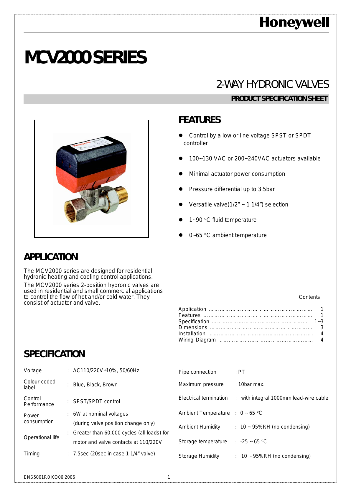
APPLICATION
The MCV2000 series are designed for residential
hydronic heating and cooling control applications.
The MCV2000 series 2-position hydronic valves are
used in residential and small commercial applications
to control the flow of hot and/or cold water. They
consist of actuator and valve.
SPECIFICATION
z 0~65 °C ambient temperature
Contents
pplication ………………………………………………… 1
Features …………………………………………………… 1
Specification ……………………………………………... 1~3
Dimensions ………………………………………………… 3
Installation …………………………………………………. 4
Wiring Diagram ……………………………………………… 4
Voltage : AC110/220V±10%, 50/60Hz
Colour-coded
label
Control
Performance
Power
consumption
Operational life
Timing : 7.5sec (20sec in case 1 1/4” valve)
ENS5001R0 KO06 2006 1
: Blue, Black, Brown
: SPST/SPDT control
: 6W at nominal voltages
(during valve position change only)
: Greater than 60,000 cycles (all loads) for
motor and valve contacts at 110/220V
Pipe connection : PT
Maximum pressure : 10bar max.
Electrical termination : with integral 1000mm lead-wire cable
Ambient Temperature : 0 ~ 65 °C
Ambient Humidity : 10 ~ 95%RH (no condensing)
Storage temperature : -25 ~ 65 °C
Storage Humidity : 10 ~ 95%RH (no condensing)
Page 2
MCV2000 SERIES HYDRONIC VALVE
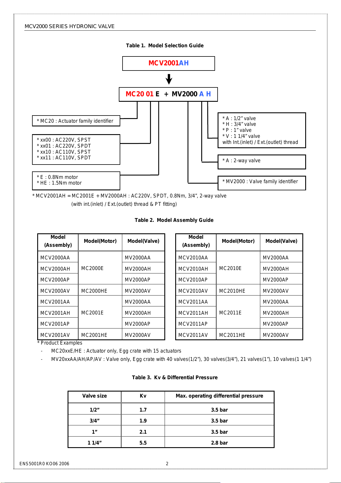
* MC20 : Actuator family identifier
Table 1. Model Selection Guide
MCV2001AH
MC20 01 E + MV2000 A H
* xx00 : AC220V, SPST
* xx01 : AC220V, SPDT
* xx10 : AC110V, SPST
* xx11 : AC110V, SPDT
* E : 0.8Nm motor
* HE : 1.5Nm motor
* MCV2001AH = MC2001E + MV2000AH : AC220V, SPDT, 0.8Nm, 3/4”, 2-way valve
(with int.(inlet) / Ext.(outlet) thread & PT fitting)
Table 2. Model Assembly Guide
Model
(Assembly)
Model(Motor) Model(Valve)
MCV2000AA MV2000AA
MCV2000AH MV2000AH
MC2000E
MCV2000AP
MCV2000AV MC2000HE MV2000AV
MV2000AP
MCV2001AA MV2000AA
MCV2001AH MV2000AH
MC2001E
MCV2001AP
MCV2001AV MC2001HE MV2000AV
* Product Examples
- MC20xxE/HE : Actuator only, Egg crate with 15 actuators
- MV20xxAA/AH/AP/AV : Valve only, Egg crate with 40 valves(1/2”), 30 valves(3/4”), 21 valves(1”), 10 valves(1 1/4”)
MV2000AP
Table 3. Kv & Differential Pressure
Valve size Kv Max. operating differential pressure
1/2” 1.7 3.5 bar
3/4” 1.9 3.5 bar
1” 2.1 3.5 bar
1 1/4” 5.5 2.8 bar
Model
(Assembly)
MCV2010AA MV2000AA
MCV2010AH MV2000AH
MCV2010AP
MCV2010AV MC2010HE MV2000AV
MCV2011AA MV2000AA
MCV2011AH MV2000AH
MCV2011AP
MCV2011AV MC2011HE MV2000AV
* A : 1/2” valve
* H : 3/4” valve
* P : 1” valve
* V : 1 1/4” valve
with Int.(inlet) / Ext.(outlet) thread
* A : 2-way valve
* MV2000 : Valve family identifier
Model(Motor) Model(Valve)
MC2010E
MV2000AP
MC2011E
MV2000AP
ENS5001R0 KO06 2006 2
Page 3

MCV2000 SERIES HYDRONIC VALVE
< 1/2” valve >
< 1” valve >
DIMENSIONS
Fig. 1 Valve Pressure Loss Characteristic for 2-way Valves
Valve Size d2(mm) d1(mm)
1/2" 95
3/4" 106
1" 125
1 1/4" 150
Fig. 2 MCV Valve Dimensions (in mm)
< 3/4” valve >
< 1 1/4 ” valve >
100(in 1")
ENS5001R0 KO06 2006 3
Page 4

MCV2000 SERIES HYDRONIC VALVE
z Take care that installer is a trained experienced service
person.
When installing this product:
z Read these instructions carefully.
Failure to follow them could damage the product or
cause a hazardous condition.
z Check the ratings given in the instructions and on the
product to make sure it is suitable for your application.
z Always conduct a through checkout after installation.
WARNING
INSTALLATION
1. The valve may be plumbed in any angle but
preferably not with the actuator head below the
horizontal level of the valve body. Make sure there is
enough room around the actuator head for servicing
or replacement.
2. The valve body can be mounted directly onto the
inlet pipe. Mount the metal flange inserted in socket
to outlet pipe. And then tighten the socket enough to
make a seal. See Figure 2 for the detail dimension.
3. Mount the valve directly in the tube or pipe. Do not
grip actuator head while making and tightening
plumbing connections. Either hold valve body in your
hand or attach adjustable spanner across the
hexagonal or flat faces on the valve body.
z Disconnect Power Supply before making electrical
connections to prevent electrical shock and equipment
damage.
CAUTION
WIRING DIAGRAM
Fig. 3 Diagram with 3-wire Actuator for SPST Controller
Fig. 4 Diagram with 3-wire Actuator for SPDT Controller
SPST Controller
L
N
SPDT Controller
NC
NO
L
N
BROWN
(CLOSE)
BLACK
(OPEN)
BLUE
BROWN
(CLOSE)
(OPEN)
BLACK
BLUE
NO
RLY
MCV2000 Series
NC
MCV2000 Series
Honeywell Co., Ltd.
Environmental & Combustion Controls
18F, Kukje Center Building 191, Hangangro-2ga,
Yongsan-gu, Seoul, 140-702, Korea
Tel. 82-2-799-6170/6194
Fax. 82-2-792-9013
ENS5001R0 KO06 2006
4
HONEYWELL
 Loading...