

Page 1
L8104A,B,C,D
68-0063-3
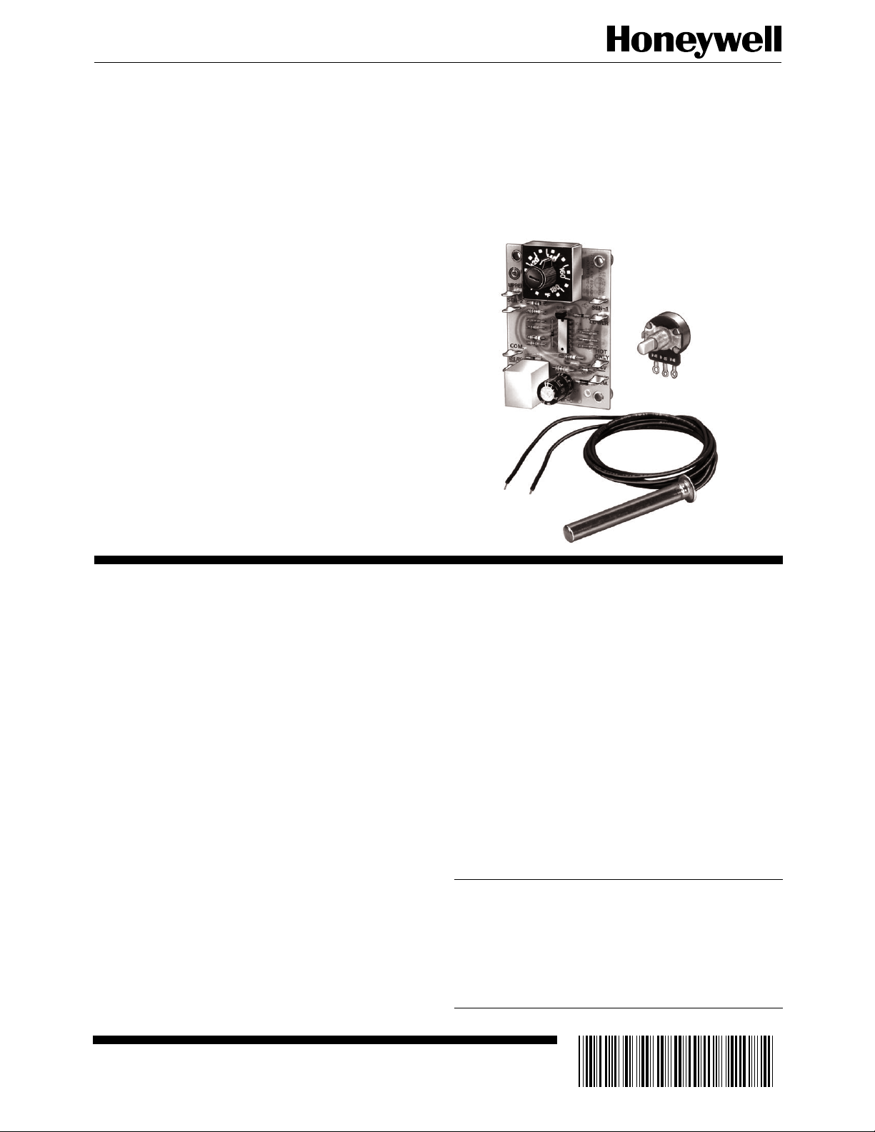
Electronic Water
Heater Controllers
The L8104A,B,C,D Electronic Controllers provide temperature control and ECO limit action for
gas water heaters.
■ L8104A,B are used in standing pilot and electronic
ignition systems.
■ L8104C,D are used only in electronic ignition sys-
tems.
■ Includes electronic module, one or two sensing bulbs,
and setpoint potentiometer (remote- or boardmounted).
■ Sensing bulb contains thermistor sensor and ECO
switch. Second bulb in L8104B,C contains thermistor only.
■ L8104A has single sensing bulb.
■ L8104B has two sensing bulbs available with upper
and lower bulb sensing authority allocated in ratios
of 1:1, 2:1, 3:1, and 4:1. Two sensing bulbs provide
temperature averaging.
■ L8104C has two sensing bulbs and manual reset
pushbutton.
■ L8104D has one sensing bulb and manual reset
pushbutton.
L8104B with
Potentiometer
Remote
Potentiometer
Sensing
Bulb
■ Temperature range is factory-set to meet application
requirements. Maximum setting temperature is 200°F
(93°C).
■ ECO limit setting is factory-set to meet application
requirements.
■ For L8104A,B, standing pilot must be manually re-
lit or ignition module must be reset when ECO shuts
off gas control.
■ For L8104C,D, ignition module must be reset using
pushbutton switch mounted on electronic control
module when ECO shuts off gas control.
■ Control circuit is accurate within ±3.5°F (1.9°C) at
maximum setpoint (200°F [93°C]; setpoint controls
are accurate within +7°F [+3.8°C], -0°F [-0°C]).
CONTENTS
Specifications ................................................. 2
Ordering Information ..................................... 2
Installation ..................................................... 5
Setting and Checkout.................................... 10
Operation ..................................................... 11
Troubleshooting ........................................... 12
Material Safety Data Sheets ......................... 15
J. H. • Rev. 6-95 • ©Honeywell Inc. 1995
1 68-0063—3
Page 2

L8104A,B,C,D
SPECIFICATIONS • ORDERING INFORMATION
Specifications
IMPORTANT: The specifications given in this publication
do not include normal manufacturing tolerances.
Therefore, this unit may not exactly match the listed
specifications. Also, this product is tested and calibrated under closely controlled conditions, and some
minor differences in performance can be expected if
those conditions are changed.
MODELS:
L8104A Electronic Commercial Water Heater Control-
ler: Includes electronic control module, single sensing
bulb containing thermistor and ECO switch, and remote- or board-mounted potentiometer.
L8104B Electronic Commercial Water Heater Control-
ler: Includes electronic control module, two sensing
bulbs (one with thermistor and ECO switch and one
with thermistor only), and remote- or board-mounted
potentiometer. Models are available with sensing authority allocated between the upper and lower sensing
bulbs in ratios of 1:1, 2:1, 3:1 and 4:1; specify when
ordering.
L8104C Electronic Commercial Water Heater Control-
ler: Same as the L8104B with additional circuitry to
manually reset the ECO switch.
L8104D Electronic Commercial Water Heater Control-
ler: Same as the L8104A with additional circuitry to
manually reset the ECO switch.
ELECTRICAL RATINGS:
Power Supply: 24 Vac, 50/60 Hz.
Gas Control Relay Contacts:
Inductive: 2A full load, 10A locked rotor.
Resistive: 2A.
TEMPERATURE SETTING RANGE: Temperature range
factory set to meet application requirements. Maximum
setting temperature is 200°F (93°C). Specify desired
range when ordering.
DIFFERENTIAL: Factory set from 2 ± 0.5°F (1 ± 0.3°C) to
15 ± 4.5°F (8 ± 2.5°C). Specify when ordering.
AMBIENT TEMPERATURE RANGE AT MODULE: 0°F
to +175°F (-18°C to +80°C).
ECO LIMIT SWITCH: Recycling or nonrecycling (one-
shot). Sensing bulb must be replaced if nonrecycling ECO
switch opens. Cutout temperature is factory set to meet
application requirements. Specify type and desired cutout
temperature when ordering. Recycling ECO is used on
manual reset models (L8104C,D).
POTENTIOMETER:
Remote: Minimum setting is at fully counterclockwise
rotation. Has 12 in. (30 cm) leadwires on terminals 1 and 2 and factory-mounted jumper across
terminals 2 and 3. Specify when ordering L8104.
Board-mounted: Setting scaleplate provided. Specify range
and board mounting when ordering L8104.
SENSING BULB: Bulbs available in several styles and
materials with various leadwire lengths. Thermistor sensor and ECO limit are factory-mounted in bulb; leads
terminate with 1/4 in. quick connects. Second bulb on
L8104B contains only thermistor sensor; leads terminate
with 3/16 in. quick connects.
MOUNTING:
Electronic Control Module: Mounts on enclosed panel
with four no. 6 or 8 screws (obtained locally) through
standoffs on module corners. Can be mounted in locations that reach up to 95 percent relative humidity
(noncondensing), but avoid locations where water
may drip on module.
Sensing Bulbs: Can be mounted in immersion well or
directly immersed if properly sealed to prevent leakage. Well or seal must be ordered separately.
Setpoint Potentiometer: Remote potentiometer mounts
through panel with nut on threaded shaft.
Ordering Information
When purchasing replacement and modernization products from your TRADELINE® wholesaler or your distributor, refer to the Tradeline
Catalog or price sheets for complete ordering number, or specify—
1. Order number. 6. Potentiometer mounted on electronic module or remote unit.
2. Temperature setting range desired. 7. Setting scale for board-mounted potentiometer.
3. Differential setting desired. 8. Sensing authority desired (L8104B,C only).
4. ECO cutout temperature desired. 9. Sensing bulb: Specify style, material, and lead wire length.
5. Recycling or nonrecycling ECO switch. 10. Additional system components, if desired.
If you have additional questions, need further information, or would like to comment on our products or services, please write or phone:
1. Your local Honeywell Home and Building Control Sales Office (please check the white pages of your phone directory).
2. Home and Building Control Customer Logistics
Honeywell Inc., 1885 Douglas Drive North
Minneapolis, Minnesota 55422-4386
In Canada—Honeywell Limited/Honeywell Limitée, 35 Dynamic Drive, Scarborough, Ontario M1V 4Z9. International Sales and
Service Offices in all principal cities of the world. Manufacturing in Australia, Canada, Finland, France, Germany, Japan, Mexico,
Netherlands, Spain, Taiwan, United Kingdom, U.S.A.
68-0063—3 2
Page 3
L8104A,B,C,D
SPECIFICATIONS
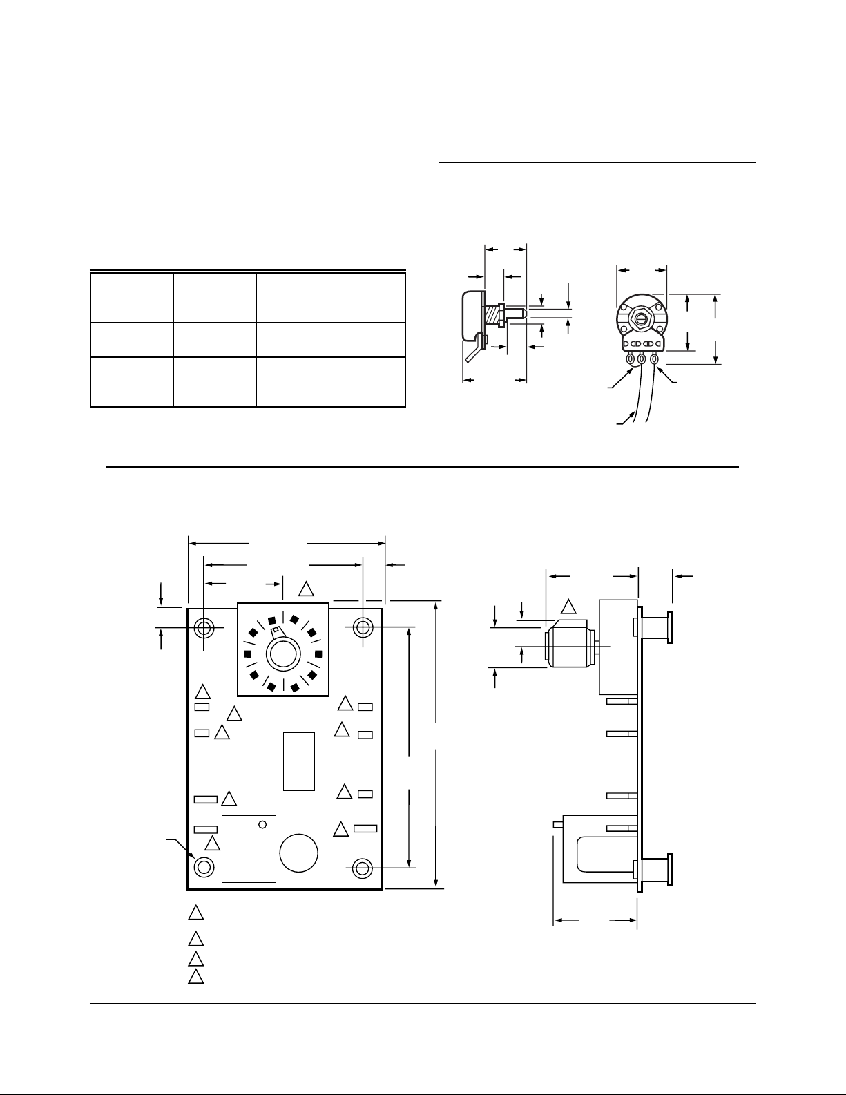
DIMENSIONS:
L8104: Fig. 1.
L8104A,B: Fig. 2.
L8104C,D: Fig. 3.
available through your Honeywell sales representative.
Please provide the ordering information indicated in the
Ordering Information section to assure correct replacement components.
APPROVALS:
Underwriters Laboratories Inc. Component Recognized:
File No. MP466, Guide No. MBPR2.
American Gas Association Certified: Report No. 70-22A.
Fig. 1—Approximate dimensions in in. (mm) of
L8104 Remote Potentiometer and Sensing Bulb.
Canadian Gas Association Certified: Report No. 1029-
CC/T-6849.
OTHER SYSTEM COMPONENTS (Order separately):
Electronic
REMOTE MOUNT POTENTIOMETER
3/4
3/8
(10)
(19)
3/8 DIA.
(10)
5/32
(4)
Ignition
System
Standing
pilot
Intermittent
pilot
Module Gas Control
— VR800, VR8200, or any
rated 2.0A or less
S86F,H;
S8600H;
VR8440, VR8204 or
any rated 2.0A or less
1-1/4 (32)
3/8
(10)
S8610F,H
12 IN. (305 MM)
REPLACEMENT PARTS: Replacement electronic control
LEADWIRES
modules, sensing bulbs, and remote potentiometers are
Fig. 2—Approximate dimensions in in. (mm) of L8104A,B Electronic Control Module.
FACTORY
INSTALLED
JUMPER
15/16
(24)
1-1/16
1-3/8
(27)
(35)
1
3
2
TERMINALS
1, 2 & 3
M413
1/4
(6)
(TWO)
.170 DIA.
(FOUR)
L8104A,B ELECTRONIC CONTROL MODULE
2-15/32 (63)
1-15/16 (49)
3/4 (19)
120
100
4
2
UPPER
4
SEN-2
COM.
3
RELAY
NO
3
1
MODELS WITH REMOTE POTENTIOMETER HAVE TWO 1/4 IN.
TAB TERMINALS IN PLACE OF THE POTENTIOMETER.
2
L8104A DOES NOT HAVE UPPER OR SEN-2 TERMINALS.
1/4 IN. TAB TERMINALS (3)
3
4
3/16 IN. TAB TERMINALS (5)
140
180
1
160
4
4
4
3
SEN-1
LOWER
24 V
HOT
ONLY
1/4
(6)
(TWO)
2-15/16
(75)
3-15/32
(88)
1/2
(13)
3/8
(10)
1-1/8 (29) 9/32
1
1 (25)
M113C
(7)
3 68-0063—3
Page 4

L8104A,B,C,D
SPECIFICATIONS
ACCESSORIES:
L8104A:
4074ENP Potentiometer Assembly: 199075A Poten-
tiometer: Clockwise turn increases temperature,
two 18 in. [46 cm] leadwires with 1/4 in. quick
connects. Washer and nut.
4074ENS Potentiometer Assembly: 199053A Potenti-
ometer: Counterclockwise turn increases temperature, two 18 in. (46 cm) leadwires with one bare wire
and one 1/4 in. quick connect. Washer and nut.
198800A One-Shot Sensor Assembly (nonrecyclying):
189°F (87°C) cutoff temperature. 11 in. (28 cm)
sensor and ECO leadwires. Sensor leadwire is 1/4
in. quick connect. ECO leadwire is stripped.
198800B One-Shot Sensor Assembly (non recycling):
200°F (93°C) cutoff temperature. 11 in. (28 cm)
sensor and ECO leadwires. Sensor leadwire is 1/4
in. quick connect. ECO leadwire is stripped.
198799B Sensor Assembly: 42 in. (107 cm) 150°C
(302°F) leadwires with 1/4 in. quick connects.
L8104B:
198799A Sensor Assembly: 42 in. (107 cm) 125°C
(257°F) leadwires with 1/4 in. quick connects.
198799B Sensor Assembly: 42 in. (107 cm) 150°C
(302°F) leadwires with 1/4 in. quick connects.
198799C Sensor Assembly: 42 in. (107 cm) 105°C
(221°F) leadwires with 1/4 in. quick connects.
198799D Sensor Assembly: 42 in. (107 cm) 105°C
(221°F) leadwires with 1/4 in. quick connects.
200636A Sensor Assembly: 180° F to 201°F (83°C to
94°C) cutoff temperature. 22 in. (56 cm) 150°C
(302°F) leadwires.
200636B Sensor Assembly: 180°F to 201°F (83°C to
94°C) cutoff temperature. 22 in. (56 cm) 150°C
(302°F) leadwires.
200636C Sensor Assembly: 180°F to 201°F (83°C to
94°C) cutoff temperature. 22 in. (56 cm) 150°C
(302°F) leadwires.
200650A Potentiometer: Clockwise turn increases tem-
perature. 8 in. (20 cm) leadwires with two 1/4 in.
quick connects.
Fig. 3—Approximate dimensions in in. (mm) of L8104C,D Electronic Control Module.
2-7/16 (62)
(TWO)
3/16 IN. TAB
TERMINALS
1/4
(6)
1 (25)
1-61/64 (50)
140
120
100
180
1
160
1/4
(6)
(TWO)
1/2
(13)
19/32
(15)
1-1/8 (29) 9/32
1
(7)
.170 DIA. (FOUR)
1/4 IN.TAB
TERMINALS
LOCKOUT
INDICATOR
LIGHT
C1
K2
VALVE
SEN-1
LOWER
COM.
24V
PV
ECO
ECO
2-61/64
(75)
(TWO)
UPPER
SEN-2
U1
K1
LOAD
PUSH BUTTON RESET
1 MODELS WITH REMOTE POTENTIOMETER HAVE TWO
1/4 IN. TAB TERMINALS IN PLACE OF THE POTENTIOMETER.
4-23/64
(111)
1 (25)
M414
68-0063—3 4
Page 5

L8104A,B,C,D
L8104A, D
L8104B, C
ELECTRONIC
CONTROL
MODULE
ENCLOSURE
SENSING
BULB
(WITH ECO)
THERMOCOUPLE
AND PILOT
BURNER
MAIN
BURNER
UPPER
SENSING BULB
(WITHOUT ECO)
THERMOCOUPLE
AND PILOT BURNER
MAIN
BURNER
LOWER
SENSING BULB
(WITH ECO)
ELECTRONIC
CONTROL
MODULE
ENCLOSURE
M132A
INSTALLATION
Installation
WHEN INSTALLING THIS PRODUCT…
1. Read these instructions carefully. Failure to follow
them could damage the product or cause a hazardous
condition.
2. Check the ratings given in the instructions and on
the product to make sure the product is suitable for your
application.
3. Installer must be a trained, experienced service
technician.
4. After installation is complete, check out product
operation as provided in these instructions.
WARNING
EXPLOSION HAZARD.
CAN CAUSE PROPERTY DAMAGE,
SEVERE INJURY OR DEATH.
This product is for use only in a system with a
pressure relief valve.
CAUTION
Disconnect power supply before wiring to prevent
electrical shock or equipment damage.
IMPORTANT: Do not bend or pull on sensor leadwires
when temperature is below freezing to prevent leadwire
damage. Install L8104 only when temperature is above
32°F (0°C).
LOCATION AND MOUNTING
Sensing Bulb(s)
The water heater manufacturer usually provides a tapping for the sensing bulb at a point where average water
temperature can be measured. With L8104B,C, the bulb
containing the thermistor and ECO switch is usually mounted
in the tapping near the bottom of the heater, and the other
bulb is located near the top. See Fig. 4. Follow the heater
manufacturer instructions.
The sensing bulb can be installed in an immersion well
or directly immersed with a suitable compression fitting to
prevent leakage. Wells and fittings must be ordered separately.
If an immersion well is used, the bulb should fit snugly
and should touch the bottom of the well for best temperature
response. Use heat-conductive compound (available in 4 oz
can as Honeywell part no. 107408) to fill the space between
the bulb and the well and improve heat transfer characteristics. Make sure the bulb is held firmly in the well.
If the sensor is directly immersed, use a 3/8 in. x 1/2 in.
compression to M.I.P. coupling or O-ring and clamp to
prevent leaks and keep bulb leadwires dry.
Electronic Control Module
Locate the electronic control module on a wall or panel
in the wiring compartment of the water heater. The module
must be within easy reach of the sensor leadwires in a
location that is convenient for reading and changing the
temperature setting. Choose a location where the module
will not be exposed to water. An enclosure is recommended
to help protect the module. Mount the module with four no.
6 or 8 screws through the corner standoffs.
Remote Mount Potentiometer
Choose a location that is convenient for reading and
changing the temperature setting. Mount the potentiometer
from the back of a panel through a 3/8 in. hole and secure it
with a nut on the threaded shaft.
WIRING
IMPORTANT: For maximum trouble free operation, run
the sensing bulb leadwires separately from any other
current-carrying wires.
All wiring must comply with local codes and ordinances. Disconnect power supply before beginning wiring.
Connect according to water heater manufacturer instructions, if available, or use Fig. 5 through 10 as a guide.
Fig. 4—Possible location of thermistor/ECO
bulb and thermistor bulb.
5 68-0063—3
Page 6

L8104A,B,C,D
INSTALLATION
Fig. 5—L8104A with board-mounted potentiometer in a standing pilot application.
Q308
COM.
RELAY
NO
L8104A
1
4
0
120
160
100
180
2
2
3
3
LOWER
3
2
SEN-1
24V
HOT
ONLY
BLACK
BLACK
RED
RED
SENSING BULB WITH
ECO SWITCH
L1
(HOT)
L2
ECO
CONNECTOR
TH TR
1
24V
VR8200
GAS VLAVE
1
POWER SUPPLY. PROVIDE DISCONNECT
MEANS AND OVERLOAD PROTECTION
AS REQUIRED.
2
1/4 IN. TAB TERMINALS (3).
3/16 IN. TAB TERMINALS (3).
3
Fig. 6—L8104A with remote potentiometer in an electronic ignition application.
BLACK
1
2
3
3
SENSING BULB WITH
ECO SWITCH
RED
RED
PILOT
VALVE
1ST
OPERATOR
1
POWER SUPPLY. PROVIDE DISCONNECT
MEANS AND OVERLOAD PROTECTION
AS REQUIRED.
2
COM
2ND
OPERATOR
GAS CONTROL
VR844, VR8440
S8600F,H,M;
S8610F,H
MV MV/PV PV
GND
(BURNER)
L8104A
COM.
4 5
RELAY
NO
4
TH-W
24V
24V
(OPT)
GND
POT
VENT
DAMPER
PLUG (OPT)
4
5
SEN-1
5
LOWER
24V
HOT
ONLY
SPARK
BLACK
SETPOINT
POTENTIOMETER
(SHOWN FROM BACK)
MAIN
VALVE
VR8440 OR
VR844
2
TERMINAL DESIGNATIONS
PILOT COM MAIN
TH TH-TR TR
M131C
1
L1
(HOT)
L2
24V
68-0063—3 6
3
FACTORY INSTALLED JUMPER; DO NOT
REMOVE.
4
1/4 IN. TAB TERMINALS (3).
3/16 IN. TAB TERMINALS (3).
5
M128B
Page 7

Fig. 7—L8104B with remote potentiometer in a standing pilot application.
L8104A,B,C,D
INSTALLATION
SENSING BULB
Q308
1
L1
(HOT)
L2
BLACK
BLACK
ECO
CONNECTOR
24V
L8104B
UPPER
SEN-2
COM.
RELAY
NO
3
4
4
3
TH TR
POT
4
4
LOWER
4
3
VR8200
GAS VLAVE
SEN-1
24V
HOT
ONLY
BLACK
BLACK
1
2
3
2
RED
RED
1
POWER SUPPLY. PROVIDE DISCONNECT
MEANS AND OVERLOAD PROTECTION
AS REQUIRED.
2
FACTORY JUMPER INSTALLED, DO NOT
REMOVE.
1/4 IN. TAB TERMINALS (3).
3
4
3/16 IN. TAB TERMINALS (5).
SETPOINT
POTENTIOMETER
(SHOWN FROM BACK)
SENSING BULB WITH
ECO SWITCH
M130C
Fig. 8—L8104B with board-mounted potentiometer in an electronic ignition application.
L8104B
1
4
0
160
120
3
24V
100
TH-W
(OPT)
180
VENT
DAMPER
PLUG (OPT)
3
4
4
3
4
SEN-1
4
LOWER
4
24V
HOT
ONLY
SPARK
BLACK
BLACK
SENSING BULB WITH
ECO SWITCH
RED
RED
PILOT
VALVE
1ST
OPERATOR
1
POWER SUPPLY. PROVIDE DISCONNECT
MEANS AND OVERLOAD PROTECTION
AS REQUIRED.
2
3
4
COM
2ND
OPERATOR
GAS CONTROL
VR844, VR8440
1/4 IN. TAB TERMINALS (3).
3/16 IN. TAB TERMINALS (5).
TERMINAL DESIGNATIONS
PILOT COM MAIN
TH TH-TR TR
SENSING BULB
S8600F,H,M;
S8610F,H
MV MV/PV PV
1
L1
(HOT)
L2
BLACK
BLACK
GND
(BURNER)
24V
UPPER
SEN-2
COM.
RELAY
NO
24V
GND
MAIN
VALVE
VR8440 OR
VR844
2
M129B
7 68-0063—3
Page 8

L8104A,B,C,D
INSTALLATION
Fig. 9—L8104C with remote-mounted potentiometer in an electronic ignition application.
BLACK
BLACK
L8104C
UPPER
SEN-2
SENSING BULB
POT
SEN-1
LOWER
COM.
24V
PILOT
1ST
OPERATOR
BLACK
BLACK
S8600H
MV MV/PV PV
COM
2ND
OPERATOR
RED
RED
GND
(BURNER)
MAIN
VALVE
DUAL VALVE
COMBINAITON
GAS CONTROL
4
24V
24V
GND
1
2
3
2
SETPOINT
POTENTIOMETER
(SHOWN FROM BACK)
SENSING BULB
WITH ECO SWITCH
L1
(HOT)
L2
1
TH-W
(OPT)
5
VENT
DAMPER
PLUG
(OPT)
5
SPARK
LOAD
POWER SUPPLY. PROVIDE DISCONNECT MEANS
1
AND OVERLOAD PROTECTION AS REQUIRED.
FACTORY INSTALLED JUMPER. DO NOT REMOVE.
2
MAXIMUM CABLE LENGTH 3 FT. (0.9M).
3
PV
ECO
ECO
VALVE
Q345, Q346, Q348,
Q362, Q381
PILOT BURNER/
IGNITER-SENSOR
CONTROLS IN 24V CIRCUIT MUST NOT BE IN GROUND LEG
4
TO TRANSFORMER.
FOR S8600H WITH TH-W TERMINAL AND VENT DAMPER PLUG,
5
CONNECT THERMOSTAT TO TH-W. LEAVE 24V OPEN.
DO NOT REMOVE VENT DAMPER PLUG.
PILOT GAS
SUPPLY
PILOT
BURNER
GROUND
3
M417
68-0063—3 8
Page 9

Fig. 10—L8104D with remote-mounted potentiometer in an electronic ignition application
L8104A,B,C,D
INSTALLATION
L8104D
POT
SEN-1
LOWER
COM.
24V
PILOT
1ST
OPERATOR
BLACK
BLACK
S8600H
MV MV/PV PV
COM
2ND
OPERATOR
RED
RED
GND
(BURNER)
MAIN
VALVE
DUAL VALVE
COMBINATION
GAS CONTROL
4
24V
24V
GND
1
2
3
2
SETPOINT
POTENTIOMETER
(SHOWN FROM BACK)
SENSING BULB
WITH ECO SWITCH
L1
(HOT)
L2
1
TH-W
(OPT)
5
VENT
DAMPER
PLUG
(OPT)
5
SPARK
LOAD
POWER SUPPLY. PROVIDE DISCONNECT MEANS
1
AND OVERLOAD PROTECTION AS REQUIRED.
FACTORY INSTALLED JUMPER. DO NOT REMOVE.
2
MAXIMUM CABLE LENGTH 3 FT. (0.9M).
3
PV
ECO
ECO
VALVE
Q345, Q346, Q348,
Q362, Q381
PILOT BURNER/
IGNITER-SENSOR
CONTROLS IN 24V CIRCUIT MUST NOT BE IN GROUND LEG
4
TO TRANSFORMER.
FOR S8600H WITH TH-W TERMINAL AND VENT DAMPER PLUG,
5
CONNECT THERMOSTAT TO TH-W. LEAVE 24V OPEN.
DO NOT REMOVE VENT DAMPER PLUG.
PILOT GAS
SUPPLY
PILOT
BURNER
GROUND
3
M415
9 68-0063—3
Page 10

L8104A,B,C,D
SETTING AND CHECKOUT
SET CONTROL TEMPERATURE
If the potentiometer is mounted on the control module,
turn the selector knob to the desired temperature.
If the potentiometer is remotely mounted, the position of
the flat part of the shaft determines the approximate control
temperature. Fully counterclockwise rotation when
the shaft is towards you is the minimum setting. Fully
clockwise rotation is the maximum setting. Actual
temperature range depends on the control module and the
potentiometer selected. See Fig. 11.
CHECKOUT
Set the L8104 above water temperature and observe the
system through one complete cycle. Make sure system
operates as desired.
To check the thermistor or thermistor/ECO assembly,
compare its resistance as measured by an ohmmeter to the
water temperature as measured by an accurate thermometer. Thermistor resistance increases as the temperature
falls. See Table 1 or 2 for the correct sensor resistance at
various temperatures.
Setting and Checkout
Fig. 11—Scale range for 3K remotely mounted
potentiometer when used with L8104B Dual
Bulb Controller.
200650 POTENTIOMETER
180oF
o
90
F
o
F
135
32 1
MAXIMUM SETTING AT
FULLY CLOCKWISE
POSITION
M133A
TABLE 1—THERMISTOR RESISTANCE AT VARIOUS TEMPERATURES IN FAHRENHEIT.
Temp-
erature
(°F)
01 23456789
Resistance (K ohms)
40 26109 25400 24712 24045 23399 22771 22163 21573 21000 20445
50 19906 19383 18876 18383 17905 17440 16990 16553 16128 15715
60 15314 14925 14548 14180 13823 13477 13140 12812 12494 12185
70 11884 11592 11308 11032 10763 10502 10248 10000 9760 9526
80 9299 9078 8862 8653 8449 8250 8057 7869 7685 7507
90 7333 7165 7000 6839 6683 6531 6383 6238 6098 5961
100 5827 5697 5570 5446 5326 5208 5094 4982 4873 4767
110 4663 4562 4464 4368 4274 4183 4094 4006 3922 3839
120 3758 3679 3602 3527 3453 3382 3312 3244 3177 3112
130 3048 2986 2925 2866 2808 2752 2697 2643 2590 2538
140 2488 2439 2391 2344 2298 2253 2209 2166 2124 2083
150 2043 2004 1966 1928 1891 1856 1820 1786 1753 1720
160 1688 1656 1625 1595 1566 1537 1509 1481 1454 1427
170 1402 1376 1351 1327 1303 1280 1257 1235 1213 1191
180 1170 1150 1129 1110 1090 1071 1053 1035 1017 999
190 982 965 949 933 917 901 886 871 857 842
200 828 814 801 788 775 762 749 737 725 713
68-0063—3 10
Page 11

SETTING AND CHECKOUT • OPERATION
TABLE 2—THERMISTOR RESISTANCE AT VARIOUS TEMPERATURES IN CELSIUS.
Temp-
erature
(°C)
0 32648 31026 29495 28049 26682 25389 24166 23010 21915 20879
10 19898 18968 18088 17253 16461 15710 14998 14322 13680 13071
20 12492 11942 11419 10922 10450 10000 9572 9165 8778 8409
30 8057 7722 7403 7099 6808 8532 6268 6016 5775 5546
40 5327 5117 4917 4726 4543 4368 4201 4042 3889 3742
50 3602 3468 3340 3217 3099 2986 2878 2774 2675 2579
60 2488 2400 2316 2235 2157 2083 2011 1942 1876 1813
70 1752 1693 1637 1582 1530 1480 1432 1385 1340 1297
80 1256 1216 1177 1140 1105 1070 1037 1005 974 944
90 916 888 861 835 810 786 763 741 719 698
01 23456789
Resistance (K ohms)
Operation
L8104A,B,C,D
L8104A,D
When the temperature at the sensing bulb drops below
the setting on the potentiometer, the relay contacts in the
electronic control module make to open the gas control or
turn on the ignition module. When the temperature rises to
the setpoint, the relay contacts open, closing the gas control
or turning off the ignition module.
The control circuit is accurate to within ±3.5°F (±1.9°C)
at maximum setpoint. (180°F (83°C) setpoint controls are
accurate within +7°F (+3.8°C), -0°F (0°C).
L8104B,C
Operation of the L8104B,C is similar to L8104A,D except the electronic control module opens and closes the
relay in response to the average of the temperatures sensed
by the upper and lower sensing bulbs.
ECO LIMIT OPERATION
If the temperature at the ECO switch rises above the
ECO limit setting, the contacts in the ECO switch break and
turn off the water heater.
L8104A,B
The L8104A,B uses a recycling ECO switch that remakes once the temperature drops below the ECO temperature. Before the system will restart, however, the system
must be reset. On a standing pilot system, the pilot must be
relit. On an electronic ignition system, power to the 100
percent lockout ignition module must be off for one minute.
A nonrecycling (one-shot) ECO switch will not remake.
The sensing bulb containing the switch must be replaced.
L8104C,D
The L8104C,D uses a recycling ECO switch. When the
ECO opens, the red LED on the electronic module lights
and the water heater is turned off. To restart the system,
press the black manual reset pushbutton until the red LED
turns off. The ECO switch is closed and the system is reset.
11 68-0063—3
Page 12

L8104A,B,C,D
TROUBLESHOOTING
If water temperature is too hot, proceed as follows:
Troubleshooting
START
DISCONNECT SENSOR LEADS FROM ELECTRONIC
CONTROL MODULE AND MEASURE RESISTANCE OF
SENSOR(S) WITH OHMMETER.
IS RESISTANCE BETWEEN 700K AND 30K OHMS
(SEE TABLE 1)?
YES
SENSOR(S) OK. DISCONNECT ECO LEADS AND
MEASURE RESISTANCE WITH OHMMETER. IS WATER
TEMPERATURE GREATER THAN 210˚F AND ECO
RESISTANCE LESS THAN 10 OHMS (SHORTED)?
NO
IS THE POTENTIOMETER REMOTE?
YES
DISCONNECT POTENTIOMETER LEADS FROM
ELECTRONIC CONTROL MODULE. MEASURE
RESISTANCE OF POTENTIOMETER WITH OHMMETER.
IS RESISTANCE GREATER THAN 1000 OHMS AT MINIMUM
TEMPERATURE SETTING (CHECKS FOR SHORT)?
YES
L8104A, B, C, D
NO
YES
NO
NO
SENSOR(S) MAY BE SHORTED OR OPEN.
CHECK FOR LOOSE, BROKEN OR SHORTED WIRES.
REPLACE SENSING BULB(S) IF NECESSARY.
REPLACE SENSING BULB WITH ECO LIMIT AND
CHECK OUT BALANCE OF SYSTEM.
REPLACE ELECTRONIC CONTROL MODULE.
RECONNECT ALL LEADS AND CHECK OUT SYSTEM.
REPLACE POTENTIOMETER.
RECONNECT ALL LEADS AND CHECK OUT SYSTEM.
POTENTIOMETER OK. REPLACE ELECTRONIC CONTROL
MODULE. RECONNECT ALL LEADS AND CHECK OUT
SYSTEM.
M134B
68-0063—3 12
Page 13

If water temperature is too cold or heater does not come on, proceed as follows:
L8104A, B
START
CHECK VOLTAGE AT 24V TERMINALS
OF ELECTRONIC CONTROL MODULE.
IS VOLTAGE BETWEEN 21.5 AND
28.5 VAC?
YES
IS THIS AN ELECTRONIC IGNITION
SYSTEM WITH 100 PERCENT LOCKOUT?
YES
DISCONNECT 24V POWER AT IGNITION
MODULE AND RECONNECT AFTER
ABOUT 1 MIN. SET POTENTIOMETER TO
MAX TEMPERATURE SETTING.
DOES HEATER TURN ON?
NO NO
NO
YES
TROUBLESHOOTING
CHECK TRANSFORMER, 120V SUPPLY,
CORRECT AS NECESSARY.
IGNITION MODULE WAS IN LOCKOUT.
OBSERVE FOR 2-3 CYCLES TO MAKE
SURE SYSTEM IS OTHERWISE OK.
L8104A,B,C,D
DISCONNECT ECO LEADS AND MEASURE
RESISTANCE WITH OHMMETER.
IS RESISTANCE GREATER THAN
100K OHMS (OPEN)?
NO
DISCONNECT SENSOR LEADS FROM
ELECTRONIC CONTROL MODULE AND
MEASURE RESISTANCE OF SENSOR(S)
WITH OHMMETER.
IS RESISTANCE BETWEEN 700 AND
30K OHMS (SEE TABLE 1)?
YES
SENSORS OK. IS THE POTENTIOMETER
REMOTE?
YES
DISCONNECT POTENTIOMETER LEADS FROM
ELECTRONIC CONTROL MODULE. MEASURE
RESISTANCE OF POTENTIOMETER WITH
OHMMETER.
IS RESISTANCE GREATER THAN 1000 OHMS AT
MINIMUM TEMPERATURE SETTING AND LESS
THAN 50 OHMS AT MAXIMUM TEMPERATURE
SETTING (CHECKS FOR OPEN OR SHORTS)?
YES
POTENTIOMETER OK. REPLACE ELECTRONIC
CONTROL MODULE. RECONNECT ALL LEADS
AND CHECK OUT SYSTEM.
YES
NO
NO
NO
REPLACE SENSING BULB WITH ECO
SWITCH AND OBSERVE SYSTEM IN
OPERATION. IF WATER HEATER DOES
NOT TURN OFF AFTER WATER
REACHES SET POINT TEMPERATURE,
REFER TO TROUBLESHOOTING IF
WATER IS TOO HOT.
SENSOR(S) MAY BE SHORTED OR
OPEN. CHECK FOR LOOSE, BROKEN
OR SHORTED WIRES. REPLACE
SENSING BULB(S) IF NECESSARY.
REPLACE ELECTRONIC CONTROL
MODULE. RECONNECT ALL LEADS
AND CHECK OUT SYSTEM.
REPLACE POTENTIOMETER.
RECONNECT ALL LEADS AND CHECK
OUT SYSTEM.
M135B
13 68-0063—3
Page 14

L8104A,B,C,D
TROUBLESHOOTING
L8104C, D
SYSTEM SHUT DOWN DUE TO ECO
OPENING.
DEPRESS AND RELEASE MANUAL
RESET BUTTON.
DOES LED TURN OFF?
YES
SYSTEM RESET.
REFER TO TROUBLESHOOTING IF
WATER IS TOO HOT.
DISCONNECT ECO LEADS AND MEASURE
RESISTANCE WITH OHMMETER.
IS RESISTANCE GREATER THAN 100K
OHMS WITH WATER TEMPERATURE LESS
THAN 180°F?
YES
REPLACE SENSING BULB WITH
ECO SWITCH.
REPLACE ELECTRONIC CONTROL MODULE.
RECONNECT ALL LEADS AND CHECK OUT
SYSTEM.
NO
YES
NO
IS LED LIT?
NO
CHECK VOLTAGE AT 24V TERMINALS
OF ELECTRONIC CONTROL MODULE.
IS VOLTAGE BETWEEN 21.5 AND
28.5 VAC?
YES
IS THIS AN ELECTRONIC IGNITION
SYSTEM WITH 100 PERCENT LOCKOUT?
YES
DISCONNECT 24V POWER AT IGNITION
MODULE AND RECONNECT AFTER
ABOUT 1 MIN. SET POTENTIOMETER TO
MAX TEMPERATURE SETTING.
DOES HEATER TURN ON?
NO NO
DISCONNECT ECO LEADS AND MEASURE
RESISTANCE WITH OHMMETER.
IS RESISTANCE GREATER THAN
100K OHMS (OPEN)?
NO
DISCONNECT SENSOR LEADS FROM
ELECTRONIC CONTROL MODULE AND
MEASURE RESISTANCE OF SENSOR(S)
WITH OHMMETER.
IS RESISTANCE BETWEEN 700K AND 30K
OHMS (SEE TABLE 1)?
YES
SENSORS OK. IS THE POTENTIOMETER
REMOTE?
YES
DISCONNECT POTENTIOMETER LEADS FROM
ELECTRONIC CONTROL MODULE. MEASURE
RESISTANCE OF POTENTIOMETER WITH
OHMMETER.
IS RESISTANCE GREATER THAN 500 OHMS AT
MINIMUM TEMPERATURE SETTING AND LESS
THAN 100 OHMS AT MAXIMUM TEMPERATURE
SETTING (CHECKS FOR OPEN OR SHORTS)?
YES
NO
YES
YES
CHECK TRANSFORMER, 120V SUPPLY,
CORRECT AS NECESSARY.
IGNITION MODULE WAS IN LOCKOUT.
OBSERVE FOR 2-3 CYCLES TO MAKE
SURE SYSTEM IS OTHERWISE OK.
REPLACE SENSING BULB WITH ECO
SWITCH.
SENSOR(S) MAY BE SHORTED OR
NO
OPEN. CHECK FOR LOOSE, BROKEN
OR SHORTED WIRES. REPLACE
SENSING BULB(S) IF NECESSARY.
REPLACE ELECTRONIC CONTROL
NO
MODULE. RECONNECT ALL LEADS
AND CHECK OUT SYSTEM.
REPLACE POTENTIOMETER.
NO
RECONNECT ALL LEADS AND CHECK
OUT SYSTEM.
POTENTIOMETER OK. REPLACE ELECTRONIC
CONTROL MODULE. RECONNECT ALL LEADS
AND CHECK OUT SYSTEM.
68-0063—3 14
M416A
Page 15

L8104A,B,C,D
MATERIAL SAFETY DATA SHEET
15 68-0063—3
Page 16

L8104A,B,C,D
MATERIAL SAFETY DATA SHEET
68-0063—3 16
Page 17

L8104A,B,C,D
MATERIAL SAFETY DATA SHEET
17 68-0063—3
Page 18

L8104A,B,C,D
MATERIAL SAFETY DATA SHEET
68-0063—3 18
Page 19

L8104A,B,C,D
MATERIAL SAFETY DATA SHEET
19 68-0063—3
Page 20

L8104A,B,C,D
MATERIAL SAFETY DATA SHEET
Home and Building Control Home and Building Control Helping You Control Your World
Honeywell Inc. Honeywell Limited—Honeywell Limitée
1985 Douglas Drive North 740 Ellesmere Road
Golden Valley, MN 55422 Scarborough, Ontario
M1P 2V9
68-0063—3 20
Printed in U.S.A. customer.honeywell.com
 Loading...