

Page 1
L7224A,C; L7248A,C,L
Oil Electronic
®
Aquastat
APPLICATION
The L7224A,C and L7248A,C,L 2012 Compliant Oil
Electronic Aquastat
temperature sensing in a UL limit-rated control with a
single sensing probe. The L7224A,C and L7248A,C,L
control the circulator, oil burner and boiler temperature.
The L7224/L7248 is “Outdoor Temperature Reset” ready
which is enabled when connected to the W8735S1000
Outdoor Reset Kit. Outdoor Reset with the L7224/L7248
is intended for all applications except for tankless coil
systems for domestic hot water. Compliance to 2012
DOE regulation ensures efficiency is maximized without
interfering with domestic hot water demand.
The L7224A,C and L7248A,C,L replace the L8124A,
L8124C, L7124A,C, L7148A and L8148A Controllers.
The L7224A,C and L7248A,C,L series controls provide
status and diagnostic information through an LED display
combined with LED lights as well as EnviraCOM™
communications enabled thermostats and diagnostic
tools to enhance the diagnostic process.
L7224/L7248 Aquastat Controllers are intended for use
in residential-type applications.
IMPORTANT
Use of Outdoor Temperature Reset on a tankless coil application requiring a Low Limit setting
will result in reduced system effectiveness and
efficiency.
®
Controllers provide electronic
Controllers
INSTALLATION INSTRUCTIONS
SPECIFICATIONS
Electrical Ratings:
Voltage: 120 Vac, 60 Hz.
Power: 7 VA maximum at 120 Vac plus external loads.
Thermostat current: 100 mA nominal at 24 Vac.
Burner Relay:
7.4 A at 120 Vac Full Load Amperage (FLA);
44.4 A inrush Locked Rotor Amperage (LRA);
Less Ignition Load: 360 VA.
Circulator Relay:
7.4 A at 120 Vac FLA; 44.4 A inrush LRA.
Zone Controller (ZC): 7.4 A at 120 Vac FLA;
44.4 A inrush LRA.
NOTE: All loads combined cannot exceed 2000 VA.
Environmental Ratings:
Temperature: -30 °F to +150 °F (-34 °C to +66 °C).
Humidity: 0 to 95% relative humidity, noncondensing.
Approvals:
Underwriters Laboratories Inc. Component Recognized.
Canadian Underwriters Laboratories Inc. Component
Recognized.
2012 DOE Compliance and Operation
Operation of this control may delay the burner operation while the residual heat is
circulated out of the boiler.
NOTE: This operation may be different than earlier electronic Aquastat®
revisions which did not implement thermal purge.
68-0281EFS-06
Page 2
L7224A,C; L7248A,C,L OIL ELECTRONIC AQUASTAT® CONTROLLERS
WARNING
M22147B
3/4
(75)
5-11/16
(145)
3/8
(10)
2-5/8 (67)
7-1/8
(181)
6-1/2
(166)
3-13/32 (86)
2x 1/4 (7) x 3/8 (9)
1/16 (2)
1-3/16
(30)
3-1/32
(77)
2-1/16 (53)
1-1/8 (29)
4-1/4 (109)
Accessories:
W8735Y1000 Wireless Outdoor Reset Kit
W873ER1000 Wireless Outdoor Reset Module
C7089R1013 Wireless Outdoor Temperature Sensor
(requires W8735ER1000)
W8735S1000 AquaReset™ Outdoor Reset Kit (includes
50022037-002 Outdoor Reset Module and
C7089U1006 Outdoor Temperature Sensor)
W8735S1008 AquaReset™ Domestic Hot Water Kit
(includes 50022037-005 Domestic Hot Water Module
and 32003971-003 Sensor)
W8735S3000 EnviraCOM™ Alarm Module
C7089U1006 Outdoor Temperature Sensor (used with the
50022037-002)
32003971-003 Temperature Sensor (used with
50022037-005)
Sensor (See Table 2).
14,000,485-016 1/4 in. (6.35 mm) diameter, 1-1/4 in.
(31.75 mm) long glass cartridge Fuse, 1A, Slow-Blow.
120650 Heat Conductive Compound.
121371AA Sensor Well Clamp.
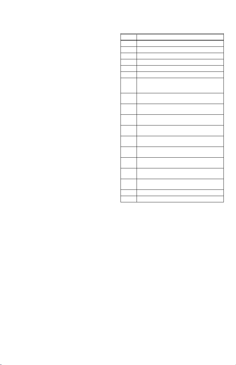
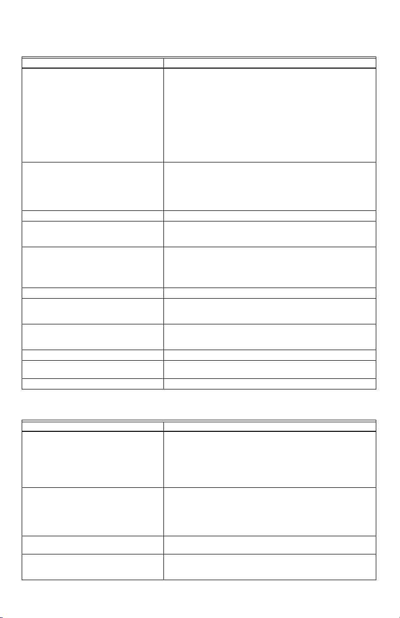
Table 1. Wells for L7224A,C; L7248A,C,L Controllers.
Part
Number
Spud Size
in. (mm)
Insertion
in. (mm)
Insulation
in. (mm)
123869A 1/2 (12.7) NPT 3 (76.2) 1-1/2 (38.1)
123870A 3/4 (19.05) NPT 3 (76.2) 1-1/2 (38.1)
Table 2. Sensors for L7224A,C and
L7248A,C,L Controllers.
Part Number
Length in.
(mm) Application
50001464-001 12 (304.8) Well-mounted controls
50001464-003 24 (609.6) Flush-mounted controls
50001464-004 36 (914.4)
50001464-005 48 (1219.2)
INSTALLATION
When Installing this Product...
1. Read these instructions carefully. Failure to follow
them could damage the product or cause a
hazardous condition.
2. Check the ratings given in the instructions and on
the product to make sure the product is suitable for
your application.
3. The installer must be a trained, experienced service
technician.
4. After installation is complete, check out product
operation as provided in these instructions.
5. Set High Limit, Low Limit and Low Limit Differential
to the settings recommended by the boiler OEM.
6. Record the maximum High Limit setting from the
replaced controller in the text box provided on the
cover insert label.
7. Record the High Limit setting at time of installation
in the text box provided on the cover insert label.
Electrical Shock Hazard.
Can cause severe injury, death or property
damage.
Disconnect power supply before beginning
installation to prevent electrical shock or
equipment damage.
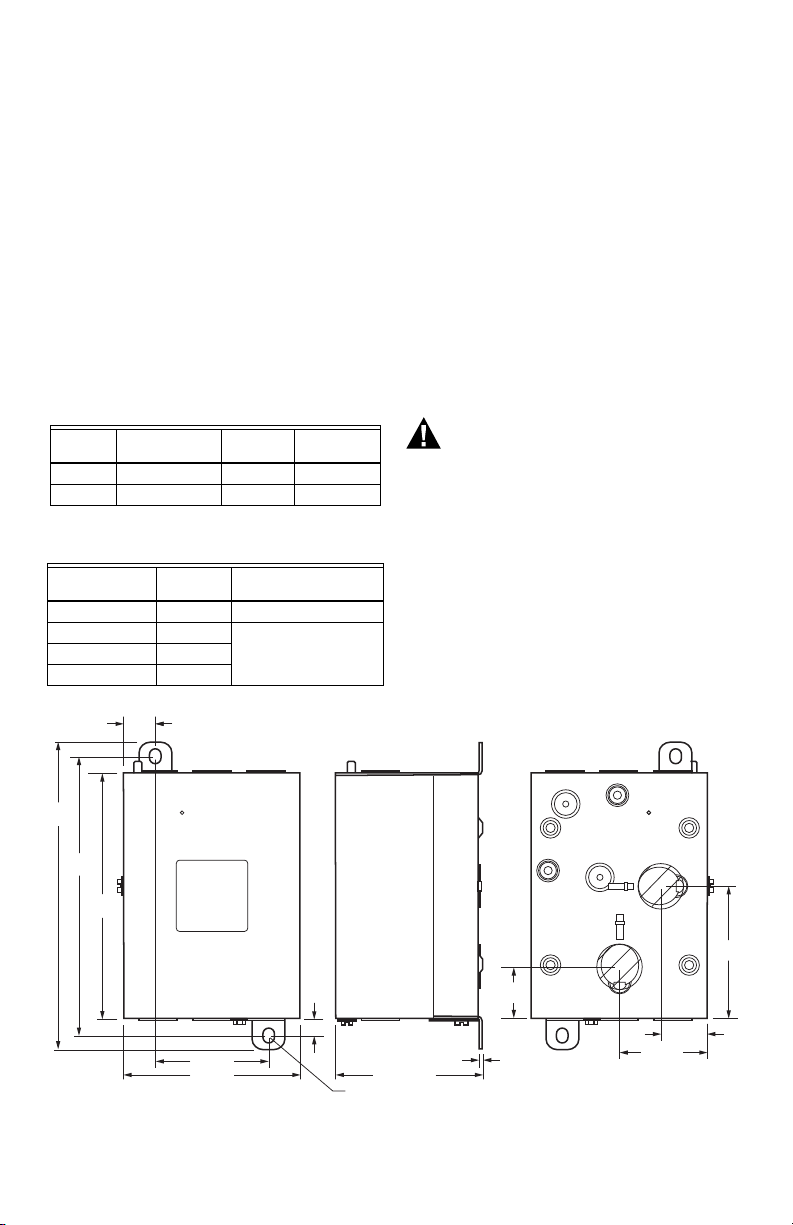
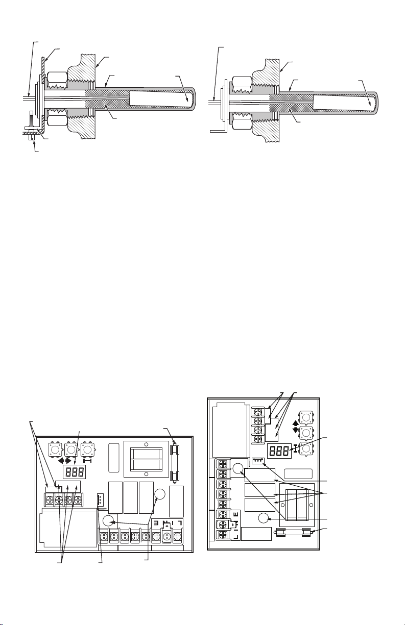
Mounting
The L7224A,C and L7248A,C,L models are available in a
well-mount, horizontal position, vertical position, or flush
mounted remote from the well versions. Dimensions for
the variety of mounting options are shown in Fig. 1. Note
that each identity will have only a single mounting option.
Fig. 1. L7224A,C; L7248A,C,L mounting dimensions in inches (mm).
68-0281EFS—06 2
Page 3
L7224A,C; L7248A,C,L OIL ELECTRONIC AQUASTAT® CONTROLLERS
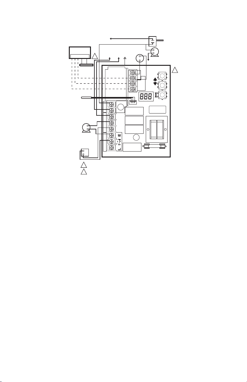
SENSOR WIRES
IMMERSION WELL
CLAMP SCREW
IMMERSION
WELL CLAMP
M16120
HEAT-CONDUCTIVE COMPOUND
(OPTIONAL)
CONTROLLER CASE
BOILER
IMMERSION
WELL
SENSOR
C1
B1
ZC
L2
LINE
C2
ZR
L1
B2
T
T3
2
1
THERMOSTAT
TERMINALS
ENVIRACOM
TM
TERMINALS
SENSOR HOLES
FUSE
M32186
SENSOR
CONNECTOR
DISPLAY
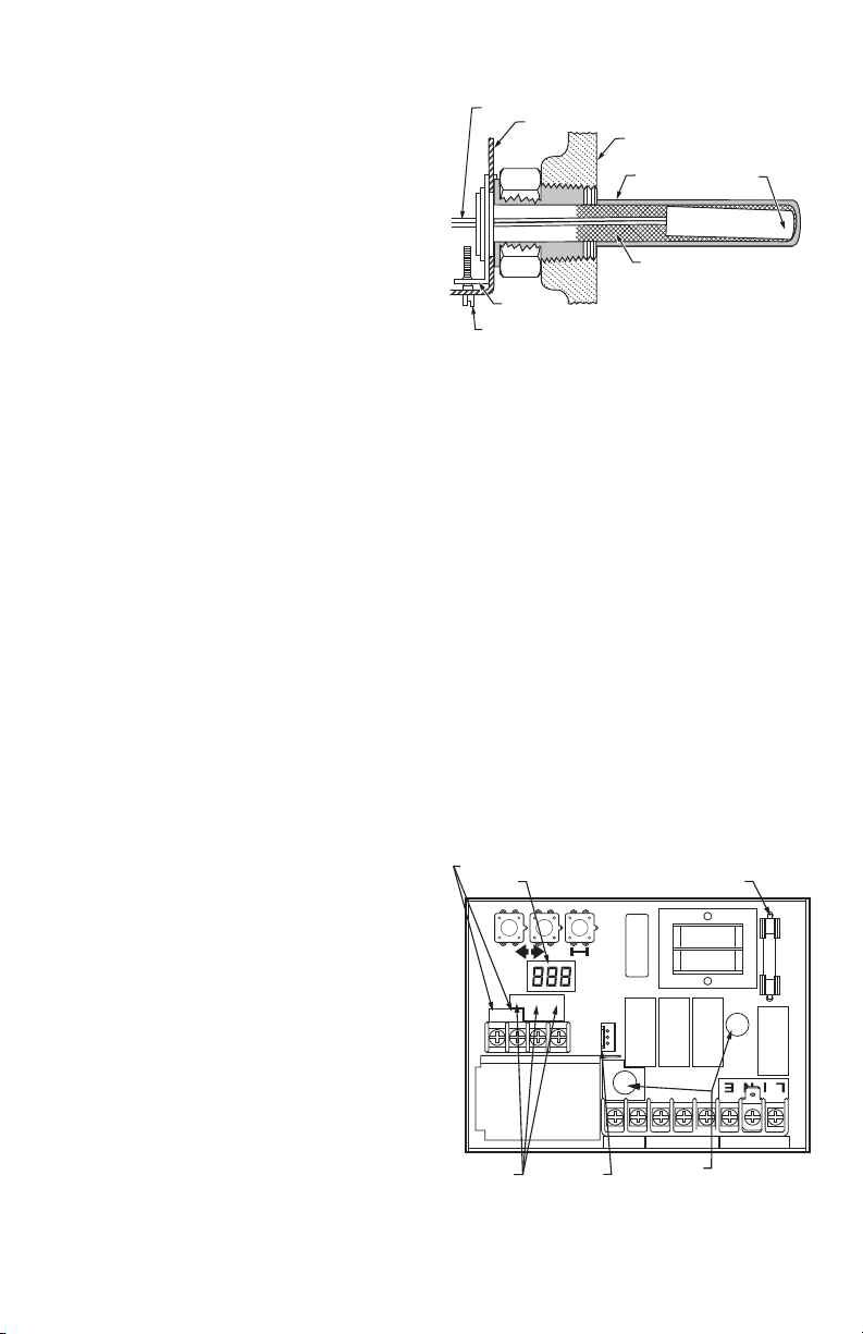
IMPORTANT
Immersion well must fit sensing element and
sensor must rest against bottom of well.
New Installation
Order well assemblies separately; see Table 1 and form
no. 68-0040, Immersion Wells and Compression Fittings
for Temperature Controllers. Boilers usually have tappings
that allow the well to be mounted horizontally so boiler
water of average temperature can circulate freely over the
well.
1. Turn off all power and drain the boiler, if applicable.
2. If no tapping is provided, prepare properly sized and
threaded tapping near the top of the boiler.
3. Sparingly coat the well threads with pipe dope.
NOTE: Do not attempt to tighten by using the case
as a handle.
4. Install the well in the boiler tapping and tighten
securely.
5. Refill boiler and check for water leakage.
6. Loosen but do not remove the well clamp screw.
7. Fit the case into the well so the clamp on the case
slides over the flange on the well.
8. Securely tighten the clamp screw.
9. Insert the sensor element into the well until it bot-
toms. See Replacement Sensor Installation section
for details. (If necessary, slightly bend the wire
inside the case to hold the sensor against the bottom of the well.)
10. Turn power ON.
11. Set High Limit, Low Limit and Low Limit Differential
to the settings recommended by the boiler OEM.
(See OPERATION section.) (See INSTALLATION
steps 6 and 7.)
12. On L7248L models, adjust ELL option to match your
configuration (see OPERATION section, and Fig. 11
and 13).
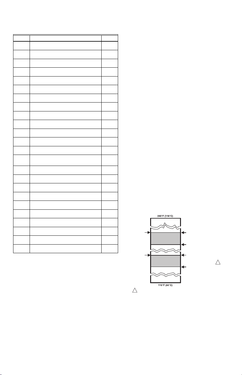
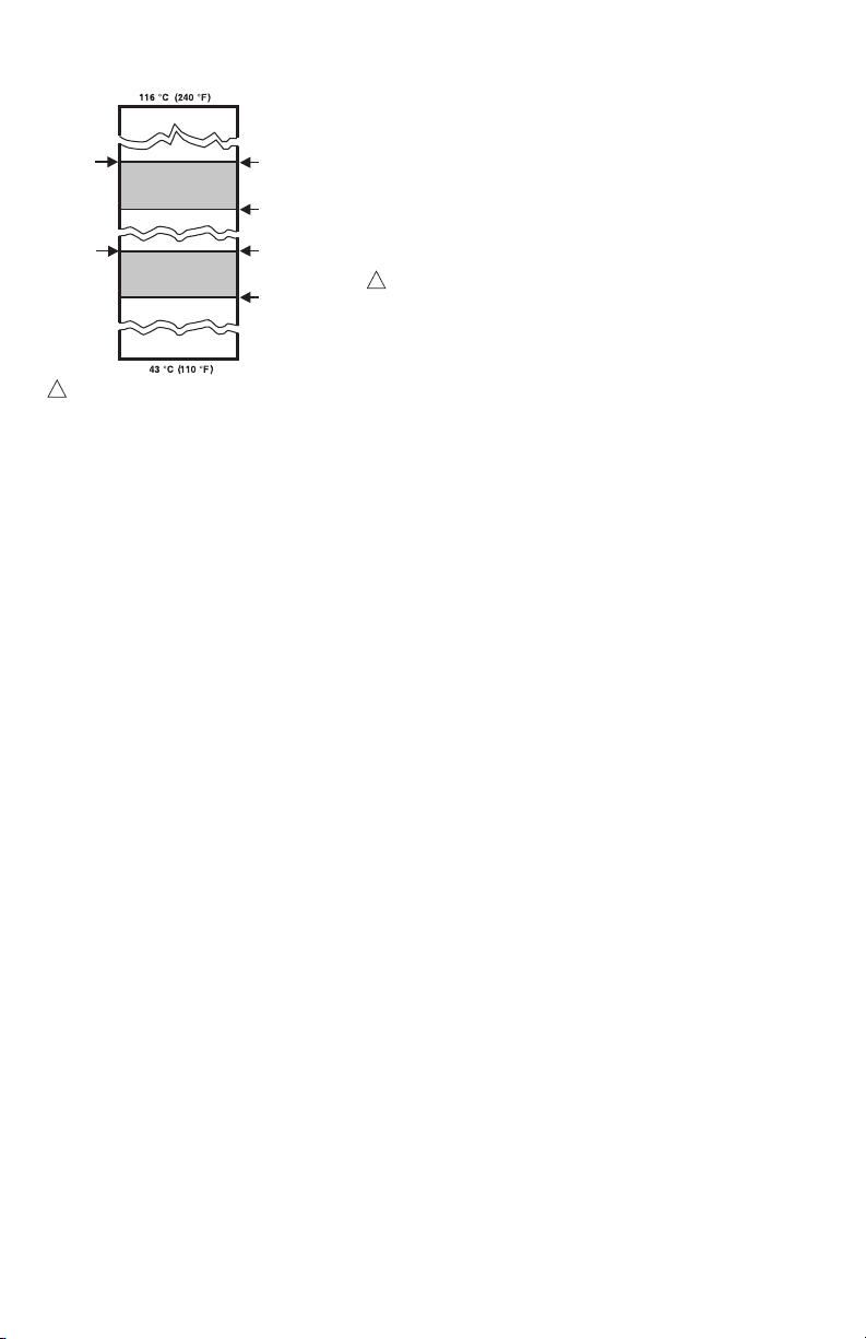
IMPORTANT
Best thermal response is obtained with a well
that snugly fits the sensor. Insert the sensor until
it rests against the bottom of the well. Use a well
of correct length and bend the wiring, if necessary, to hold the bulb against the bottom of the
well.
If the well is not a snug fit on the sensor, use the
heat-conductive compound (furnished with
TRADELINE
plastic bag of compound lengthwise and twist it
gently. Then snip off end of bag and work the
open end of the bag all the way into the well.
Slowly pull out the bag while squeezing it firmly
to distribute compound evenly in the well. Bend
the wiring, if necessary, to hold the sensor
against the bottom of the well and to hold outer
end of the sensor in firm contact with the side of
the well. See Fig. 2. Wipe excess compound
from the outer end of the well.
®
models) as follows: Fold the
Fig. 2. Position of sensor in immersion well.
Flush-Mounted Aquastat Replacement
Turn off all power and remove the old control. Refer to the
cover insert of the old control to identify and tag each
external lead as it is disconnected. If the old well is
unsuitable for the new installation, remove it and replace it
with a suitable new well. If the old well is suitable, use it.
Well-Mounted Aquastat Replacement
Turn off all power and remove the old control. Refer to the
cover insert of the old control to identify and tag each
external lead as it is disconnected. If the old well is
unsuitable for the new installation, remove it and proceed
with instructions for new installation. If the old well is
suitable, use it.
1. Loosen, but do not remove, the well clamp screw on
the side of the control case.
2. Position immersion well clamp snugly over the
flange of the adapter and tighten the clamp screw.
3. Insert the sensor into the well as shown in Fig. 2 or
3. (See Replacement Sensor Installation section for
details.)
Fig. 3. Circuit board, showing sensor connection and
well holes for horizontal mount models.
3 68-0281EFS—06
Page 4
L7224A,C; L7248A,C,L OIL ELECTRONIC AQUASTAT® CONTROLLERS
WARNING
SENSOR WIRES
M22026
HEAT-CONDUCTIVE COMPOUND
(OPTIONAL)
BOILER
IMMERSION
WELL
SENSOR
C1
B1
ZC
L2
LINE
C2
ZR
L1
B2
T
T3
2
1
THERMOSTAT
TERMINALS
ENVIRACOM
TM
TERMINALS
DISPLAY
SENSOR
CONNECTOR
SENSOR HOLES
FUSE
RELAYS
M32187
WIRING
Electrical Shock Hazard.
Can cause serious injury or death.
Disconnect power supply before making wiring
connections to prevent electrical shock or
equipment damage.
All wiring must comply with local electrical codes and
ordinances. Do not exceed the specifications in the
Application section when wiring this control. Use wire
rated for 194 °F (90 °C) or higher.
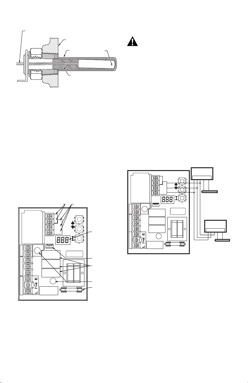
Fig. 4. Replacement sensor installation.
Replacement Sensor Installation
Turn off all power and:
1. Carefully disconnect sensor from circuit board by
pulling gently on the connector.
2. Gently pull sensor from thermo well and through cir-
cuit board by pulling on leadwires.
3. Carefully align replacement sensor with hole in cir-
cuit board and guide through Aquastat case and
into well. (See Fig. 5).
4. Make sure sensor is fully seated to bottom of well
(See Fig. 4). Use a small pencil to measure depth of
sensor in well, if necessary.
5. Connect sensor to circuit board by pressing con-
nector on sensor unit into mating connector on circuit board (See Fig. 5).
6. For remote sensors (flush-mounted Aquastat Con-
trollers) be sure to use 121571AA Clamp (see
Accessories) to securely hold sensor in place.
IMPORTANT
The terminals on these Aquastat Controllers are
approved for use with copper wire only.
Follow the appropriate wiring diagrams shown on the
inside of the front cover of the L7224A,C; L7248A,C,L or
in Fig. 8–13.
Refer to Fig. 6 for Connections for the optional Outdoor
Reset Module and the Domestic Hot Water (DHW)
module. In subsequent wiring diagrams these modules
will be displayed with a dotted line signifying that they are
optional.
ZR
L1
L2
C2
B2
C1
B1
ZC
Fig. 6. Wiring the Outdoor Reset Module and the
50022037-002
OUTDOOR
RESET MODULE
T
T
3
2
1
LINE
1 2 3 OT OT
Domestic Hot Water Module.
C7089U1006
OUTDOOR
SENSOR
50022037-005
DOMESTIC HOT
WATER MODULE
1 2 3 TS TS
32003971-003
TEMPERATURE
SENSOR
M29651
Fig. 5. Circuit board, showing sensor connection and
Fuse
The 1 Amp fuse located near the transformer is intended
to protect the EnviraCOM circuit from incorrect wiring. The
Aquastat will continue to function should the fuse blow or
be removed though no EnviraCOM communication will be
possible on the bus and Err 6 will be displayed. See
Tabl e 1 0.
68-0281EFS—06 4
well holes for vertical mount models.
OPERATION
General
The L7224A,C and L7248A,C,L Oil Electronic Aquastat
Controllers are primary safety limit-rated devices
designed for use with oil fired boilers with line voltage
burners and circulators. Many boilers do not include
wiring or control compartments as part of the design, but
are provided with an integral, replaceable, immersion well
that is the mounting hardware for the Aquastat
Controllers. Wiring to the other controls is done through
flexible metal conduit.
For boilers that do include a remotely (flush) mounted
control, the wiring may be completed with conduit or
routed behind the boiler sheet metal.
Page 5
L7224A,C; L7248A,C,L OIL ELECTRONIC AQUASTAT® CONTROLLERS
A separate electromechanical high-limit is not required in
a system that uses this control to meet Underwriters
Laboratories Inc. requirements for oil-fired boiler
assemblies, UL 726.
On the L7224 models, the High Limit, Low Limit, Low Limit
Differential, and Anti Short-Cycle time can be adjusted to
the setting recommended by the boiler OEM. On the
L7248 models, the High Limit, and Anti Short-Cycle time
are also adjustable, see “Adjusting Settings”.
The overall range of the High Limit is from 130 °F to
240 °F (54 °C to 116 °C). Select devices may have
different ranges. Some models have limited ranges on the
High Limit setpoint; this limited range is listed on the
device label.
Some models also have a Low Limit and Low Limit
Differential adjustment. The range of the Low Limit is from
110 °F to 220 °F (43 °C to 104 °C). Select devices may
have different ranges.
The Zr setting can be set to DHW, Zoning, or for tankless
coil applications depending on the L7224/L7248.
If a W8735S1000 AquaReset™ Outdoor Reset Module is
installed, the reset curve can be set by entering the
minimum outdoor temperature, minimum (boiler)
temperature, and maximum outdoor temperature on the
3-digit display. The range of the minimum outdoor
temperature is from -40 °F to 40 °F (-40 °C to 4.4 °C) and
has a default setting of 0 °F (-18 °C). The range of the
maximum outdoor temperature is from 30 °F to 70 °F
(-1.1 °C to 21.1 °C) and has a default setting of 40 °F. The
range of the minimum (water or boiler) temperature is
from 80 °F to 180 °F (26.7 °C to 82.2 °C) and has a
default setting of 130 °F. See the “Outdoor Reset Module”
Installation Instructions (form number 69-2335) for more
information on setting the boiler reset curve and all related
parameters.
The L7224A,C and L7248A,C,L are designed for use with
24 Vac electronic and electromechanical thermostats or
EnviraCOM™ enabled thermostats, and have screw-type
terminals for easy field connection.
Adjusting Settings
To discourage unauthorized changing of Aquastat
settings, a procedure to enter the ADJUSTMENT mode is
required. To enter the ADJUSTMENT mode, press the
UP, DOWN, and I buttons (Refer to Fig. 5) simultaneously
for three seconds. Press the I button until the feature
requiring adjustment is displayed:
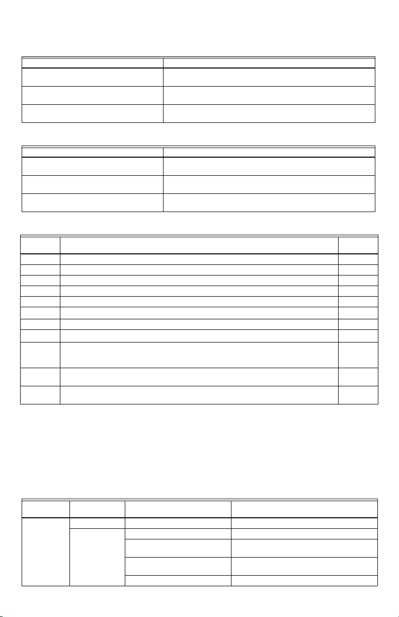
Table 3. Adjustable Features.
Display Definition
HL_ High Limit.
FP_ Frost Protection (ON/OFF) (L7248L only)
Hdf High Limit Differential.
LL_ Low Limit. (L7224A, C)
Ldf Low Limit Differential (L7224A, C)
ELL External Low Limit (L7248L only)
duu ZR input configured as external Domestic Hot
Water (DHW) request (ON/OFF) (L7224A,C/
L7248L)
ASC Anti Short-Cycle Timeout (seconds); “OFF” is
disabled.
otL* Outdoor Temperature Low (minimum)
parameter for the outdoor reset curve (°F or °C)
otH* Outdoor Temperature High (maximum)
parameter for outdoor reset curve (°F or °C)
btL* Boiler Temperature Low (minimum) parameter
for outdoor reset curve
bP* Boost Period (minutes). “OFF” is displayed if
Boost is inactive
bS* Boost step (°F or °C) shown only if Boost is
active (bP=ON)
UUS* Warm Weather Shutdown Temperature
(°F or °C)
tPL** Thermal Purging Limit Temperature (°F or °C),
“OFF” if disabled
tPt** Termal Purging Time Delay (minutes), shown
only if tPL is enabled
PC Pump Cycling (ON / OFF)
F-C Temperature units (°F or °C)
* Settings available for adjustment on the 3-digit display
only if the W8735S1000 AquaReset Outdoor Reset
Module is installed.
**Settings available for adjustment only when the
W8735S1000 AquaReset Outdoor Reset Kit is NOT
installed.
Then press the UP and/or DOWN buttons to move the set
point to the desired value, to change between °F and °C,
or to enable (On) or disable (Off) the External Low Limit.
After 60 seconds without any button inputs, the control will
automatically return to the RUN mode.
Display
In the RUN mode, the Aquastat will flash “bt” (boiler temp)
followed by the temperature (i.e., 220), followed by °F or
°C.
To read boiler settings, press the I key to read the
parameter of interest. For example, press I and High Limit
(HL) is displayed, followed by a three-digit number, i.e.,
220, followed by °F or °C. Pressing the I button again (on
L7224 models) will display the Low Limit (LL) followed by
a three-digit number and the corresponding degree
designator. See Display Readout, Table 4.
After approximately 60 seconds without any key presses,
the display will enter a dim display mode. To return to the
bright display mode, simply press any key.
5 68-0281EFS—06
Page 6
L7224A,C; L7248A,C,L OIL ELECTRONIC AQUASTAT® CONTROLLERS
LOW LIMIT
SETTING
HIGH LIMIT
SETTING
SWITCH BREAKS ON
TEMPERATURE RISE.
BURNER TURNS OFF.
CIRCULATOR OPERATES
ON A CALL FOR HEAT.
SWITCH MAKES ON
TEMPERATURE FALL.
BURNER OPERATES ON A
CALL FOR HEAT.
WITH NO HEATING
DEMAND, SWITCH BREAKS
ON TEMPERATURE RISE.
SWITCH MAKES ON
TEMPERATURE FALL,
BURNER IS ON TO
MAINTAIN MINIMUM
WATER TEMPERATURE.
CIRCULATOR IS OFF.
M23364
WHEN WATER REACHES LOW LIMIT SETTING, THE BURNER SHUTS
OFF OR THE CIRCULATOR PUMP STARTS (WHEN CALLING FOR HEAT).
1
1
10ºF (6ºC)
DIFFERENCE
L7224: 10°F (6°C)
DIFFERENCE
L7248: 15°F (8°C)
DIFFERENCE
Table 4. Display readout definitions.
Text Description Display
Err Error Code (if one is present)
bT Boiler Temperature
High Limit
1
HL
HdF High Limit Differential
LL Low Limit (L7224 only)
Ldf Low Limit Differential (L7224 only)
tt Local Thermostat Status
ttE EnviraCOM Thermostat Status
brn B1 (Burner) output (ON or OFF)
Cir C1 (Circulator) output (ON or OFF)
ZC ZC (Zone Control) output (ON or OFF)
Zr ZR (Zone Request) Call for HEAT (ON or OFF)
ELL External Low Limit Enabled (L7248L only)
duu ZR Configured as Domestic Hot Water
Request (L7224, L7248L only)
ASC Anti Short-Cycle Timeout
bSP
Boiler Set-Point
dhc
DHW Module Connected
ot
Outdoor Temperature
otL
Outdoor Temperature Low
otH
Outdoor Temperature High
btL
Boiler Temperature Low
bP
Boost Period
bS
Boost Step
UUS
Warm Weather Shutdown Temperature
1
Display shows local setting; not the setting as modified by an
external enviracom control.
2
Settings are viewable only if the outdoor reset module and out-
door temperature sensor are installed and functioning properly.
3
Settings are viewable only if the domestic hot water module
and sensor are installed and functioning properly.
Operation
The L7224 and L7248 models can be in any of four
operational states: Normal, High Limit, Low Limit and
Error. The controller moves back and forth from
High Limit to Normal to Low Limit state as part of normal
operation. Only devices having High Limit settings are
restricted to the High Limit and Normal states. However,
the controller will enter the Error state when there is an
abnormal condition. The operating states are:
1. Normal: Boiler temperature went below the High
Limit setting (minus the Differential) and has not
exceeded the High Limit setting; or, the boiler
temperature went above the Low Limit setting and
68-0281EFS—06 6
2
3
2
2
2
2
(YES or NO)
2
2
2
has not gone below the Low Limit setting (minus the
Differential); or, ZR input is not powered with 120
Vac (only L7248L with ELL set On).
2. High Limit: Boiler temperature went above the High
Limit setting and has not dropped below the High
Limit setting (minus the Differential).
3. Low Limit: Boiler temperature went below the Low
Limit setting (minus the Low Limit Differential) and
has not gone above the Low Limit setting; or, ZR
input is powered with 120 Vac (only L7248L with
ELL set On).
4. Error: The controller has detected an error condition
(e.g., open sensor) and has shut down the burner
output. The ZC output is energized. The controller
continues to monitor the system and automatically
restarts if the error condition clears. Refer toTable 4.
The operating sequence for the L7224/L7248 is shown in
Table 6–9.
High Limit Controller
The High Limit opens and turns off the burner when the
water temperature reaches the setpoint. The High Limit
automatically resets after the water temperature drops
past the setpoint and through the Differential. The L7248
models have High Limit Differential presets of 15 °F
(8 °C). The L7224 models have High Limit Differential
presets of 10 °F (6 °C).
Low Limit and Circulator Controller
On a temperature rise, with the adjustable Differential at
the default setting of 10 °F (6 °C), the burner circuit
breaks and the circulator circuit makes (assuming no call
for heat is present) at the Low Limit setpoint. On a
temperature drop of 10 °F (6 °C) below the Low Limit
setpoint, the burner circuit makes and the circulator circuit
breaks. See Fig. 7.
Fig. 7. Setpoints and differentials.
Anti Short-Cycle Feature
The Anti Short-Cycle feature allows for field selection of a
delay time between burner cycles. Should a call for heat
occur following the end of the previous heat cycle and
before the Anti Short-Cycle delay time is expired, the
circulator will be allowed to run, but the burner will be held
off until the time has elapsed. The range of the Anti ShortCycle time is from OFF to five minutes.
Page 7
L7224A,C; L7248A,C,L OIL ELECTRONIC AQUASTAT® CONTROLLERS
NOTE: This feature is blocked if a Domestic Hot
Water demand occurs. Domestic Hot Water
demands are serviced immediately, without
any delay.
NOTE: When the Aquastat is connected to the oil
primary and/or thermostat via the EnviraCOM
bus, the Anti Short-Cycle time does not apply
to recycle events such as loss of airflow or
flame. It applies only to loss of demand.
ZR-Domestic Hot Water (DHW) Request
The ZR terminal can be selected to service an indirect
water heater heat request. This parameter is set via the 3
digit display (see Adjusting Settings section of this
document). A heat request via the ZR terminal will have
priority over all other features such as the Anti ShortCycle feature or those enabled by the Outdoor Reset
Module (See form #69-2335 for more information).
Frost Protection
The Frost Protection function protects the boiler and
potentially the boiler plumbing from possible damage
which may occur should the water in the system begin to
freeze. The Frost Protection feature is enabled only in the
L7248 (cold start models). The feature default setting is
enabled (ON), but can be disabled using the 3-digit
display. See “Adjusting Settings” on page 5.
When the Boiler temperature drops to the Frost Protection
Limit temperature (fixed 40 °F), the burner is forced on.
The Circulator and ZC outputs remain in the same state
as before the Frost Protection function was enabled.
They can be either ON or OFF during the Frost Protection
cycle.
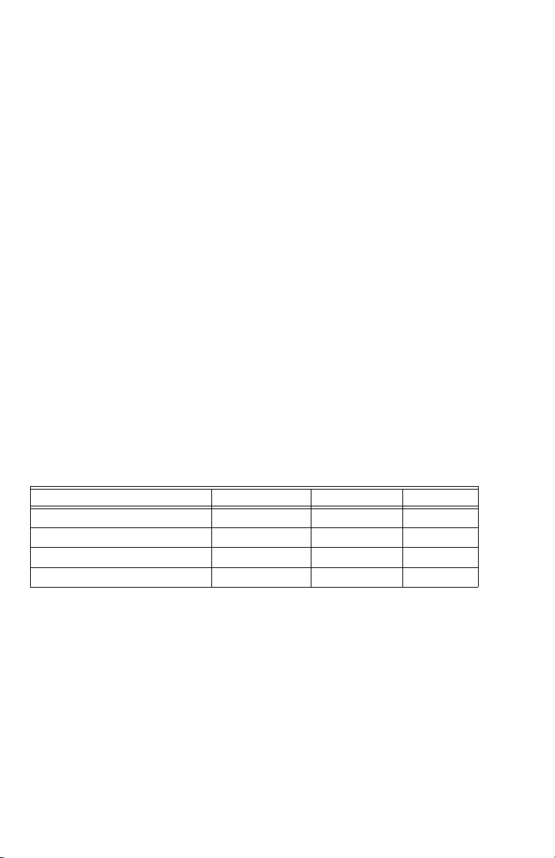
Table 5. Thermal Purge Settings.
Parameter name Minimum value Maximum Value Default
Boiler temperature drop Not adjustable Not adjustable 10 °F
Thermal purge temperature limit 120 °F (or OFF) 160 °F 140 °F (L7248)
Thermal purge temperature rate of drop Not adjustable Not adjustable 5 °F/minute
Thermal purge time delay 1 minute 10 minutes 2 minutes
When the Boiler temperature reaches the Frost Protection
Limit temperature plus a fixed 10 °F differential, the burner
is turned off unless requested to stay on due to a different
demand.
Thermal Purge Operation
The intent of thermal purge is to insure usable residual
heat in the boiler is circulated until it is sufficiently
depleted from the system before the burner is allowed to
fire. To that end, on a call for heat, the burner is held off
while the circulator runs until the boiler temperature drops
to the thermal purge temperature or a time delay is
exceeded. Both of these parameters are adjustable.
When the boiler temperature reaches the thermal purge
temperature, the burner is allowed to fire. Thermal purge
is only applied to cold start Aquastat models (L7248) and
will not interfere with domestic hot water call for heat or
boilers equipped with Honeywell outdoor reset
accessories. For warm start models where a Low Limit
must be set, thermal purge is not applied.
In addition to the thermal purge temperature and thermal
purge time delay parameters, two other conditions release
the Aquastat from thermal purge in order to maintain
comfort in the space:
• The boiler temperature has dropped 10 °F from the
beginning of the thermal purge.
• Boiler temperature is cooling at a rate greater than
5 °F/minute while the circulator is running.
The thermal purge feature applies to single zone as well
as multi-zone applications.
Thermal Purge Settings
Some thermal purge parameters are configurable using
the 3 digit display. See “Adjusting Settings” on page 5.
Thermal purge may be disabled by setting the thermal
purge temperature limit to "OFF".
Thermal Purge and Domestic Hot Water
The thermal purge feature is automatically disabled
whenever there is a call for domestic hot water from the Zr
terminal to ensure hot water is available in a timely
manner. See “ZR-Domestic Hot Water (DHW) Request”
on page 7.
Pump Cycling
The Pump Cycling feature exercises the system pump for
15 seconds after a non-adjustable five day period of no
boiler activity. The Pump Cycling feature default setting is
enabled (ON) but can be disabled (OFF) using the 3-digit
display. See “Adjusting Settings” on page 5.
CHECKOUT
Put the system into operation and observe at least one
complete cycle to make sure that the controller operates
properly. See TROUBLESHOOTING section to use LED
to assist in determining system operation.
TROUBLESHOOTING
When attempting to diagnose system performance,
reference to the LED display can help to identify specific
areas not working properly. The LED display will scroll
Err, followed by a digit (1-8). Refer to Table 10 and 11 for
a description of each error and suggested actions.
7 68-0281EFS—06
Page 8
L7224A,C; L7248A,C,L OIL ELECTRONIC AQUASTAT® CONTROLLERS
LINE VOLTAGE INDIRECT
LINE
TANK AQUASTAT
L2
T
T3
2
1
INDIRECT
TANK
CIRCULATOR
M32023
2
50022037-002
OUTDOOR
RESET MODULE
1 2 3 OT OT
C7089U
OUTDOOR
SENSOR
SENSOR
LINE
VOLTAGE
CIRCULATOR
LINE
VOLTAGE
OIL BURNER
RELAY
1
2
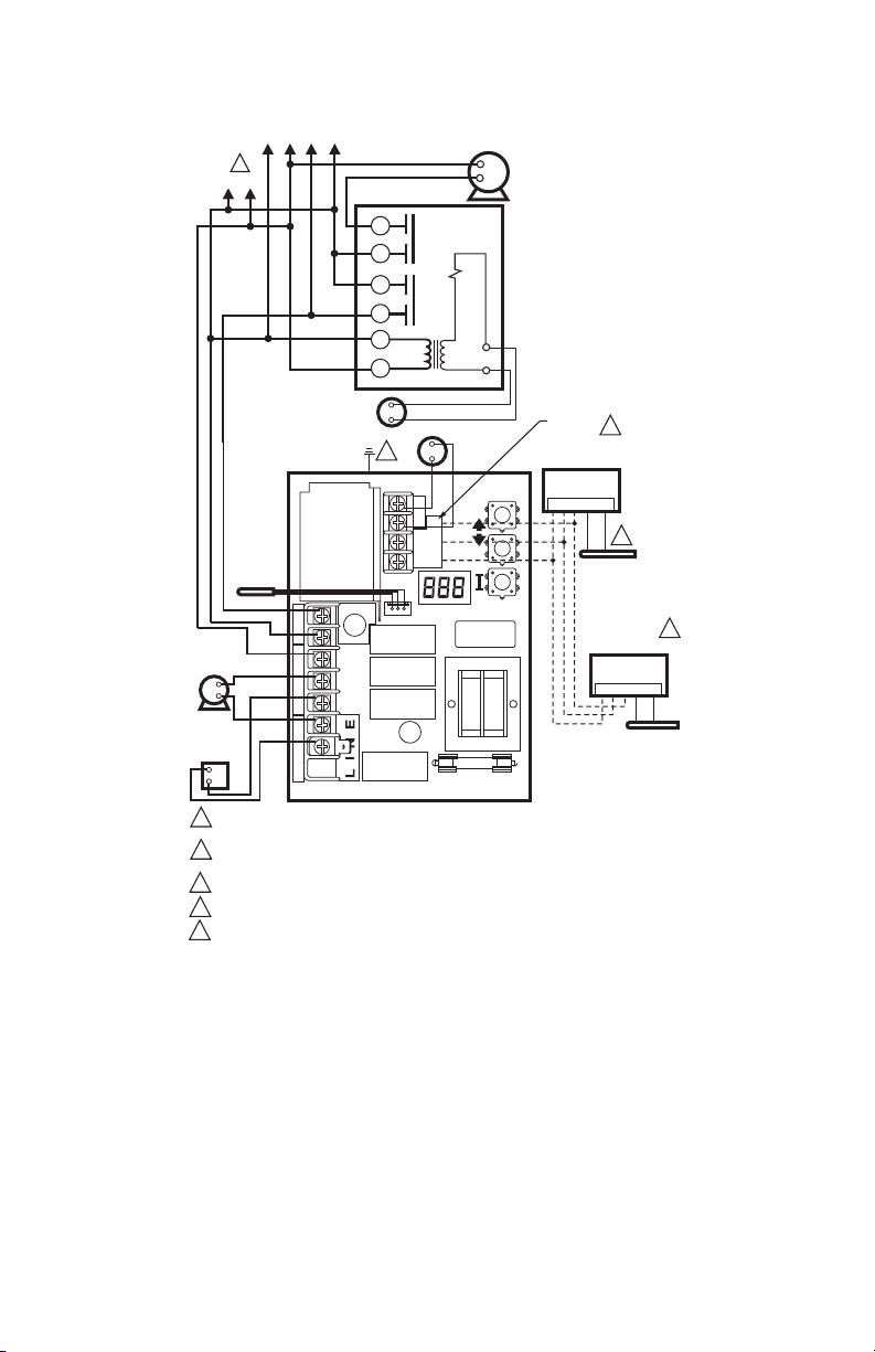
Fig. 8. L7224A,C; L7248L single heat zone with indirect water tank and circulators. Optional Outdoor Reset
L1
(HOT)
L1
(HOT)
1
OUTDOOR RESET MODULE IS OPTIONAL.
FOR BEST PERFORMANCE SET DUU=”ON”.
L2
ZR
L1
L2
C2
B2
C1
B1
ZC
Module.
68-0281EFS—06 8
Page 9
L7224A,C; L7248A,C,L OIL ELECTRONIC AQUASTAT® CONTROLLERS
Table 6. L7224/L7248 Controller Operating Sequence.
Action System Response
Thermostat calls for heat. Circulator starts when water temperature is above Low Limit setting (if
Boiler temperature exceeds the High Limit. Burner is turned off. Burner restarts when the water temperature
applicable) or above the Thermal Purge Temperature Limit (tPL) if
Thermal Purge is enabled. Boiler temperature is checked. Burner
starts when water temperature is below High Limit setting minus the
differential or at or below the Thermal Purge Temperature Limit (tPL)
for cold start boilers if the Thermal Purge Temperature Limit is
enabled. If tPL is enabled, the burner may also start if the boiler
temperature is cooling at 10 ºF or greater per minute or the Thermal
Purge Time Delay (tPt) has expired.
If Anti Short-Cycle Time is enabled, the burner does not start until the
set Anti Short-Cycle Time between cycles expires after the previous
call for heat was satisfied.
drops below the High Limit setting minus the Differential. If Thermal
Purge is enabled, the burner is turned on when either the Thermal
Purge Temperature Limit is reached, the Thermal Purge Time Delay
has expired or the boiler temperature cooling rate exceeds 10 ºF/
minute.
Thermostat is satisfied. Circulator and burner turn off.
Boiler temperature drops below the Low Limit
setting minus the differential (if applicable).
Error condition
1-5.
Burner is turned on, Circulator is turned off. Burner stops when the
water temperature exceeds the Low Limit setting. Power to Zc is
removed.
If an error condition is detected, all outputs except ZC are shut down.
Burner is off. Control continues to function and restarts when error is
corrected.
During the error check sequence, the system checks for drift in the
sensor and corrosion in the connections.
Error condition 6. EnviraCOM communication is not available.
Error condition 7. The control has reset the High Limit, Low Limit and Differential setting to
Error condition 8. If the error condition is detected, all outputs except ZC are shut down.
a default setting and will continue to run at those settings.
Performance of the system will be degraded.
Burner is off. Control continues to function and restarts when all three
user keys have been pressed longer than 60 seconds.
Error condition 9*. System continues to run with no outdoor reset functionality
Error condition 10*. System continues to run with outdoor reset parameters enabled as
programmed. Error cleared automatically.
Error condition 11*. System continues to run with boiler temp set to High Limit.
* Error condition only available when the Outdoor Reset Module is installed.
Table 7. L7224/L7248 Controller Operating Sequence with multiple zones connected through the ZR terminal.
Action System Response
Zone Request (ZR) terminal is connected to
L1 (Zone calls for heat).
Boiler temperature exceeds the High Limit. Burner is turned off. Burner restarts when the water temperature
Zone Request input is de-energized (Zones
are satisfied).
Boiler temperature drops below the Low Limit
setting minus the differential (if applicable).
Boiler temperature is checked. Burner starts when water temperature
is below High Limit setting or at or below the Thermal Purge
Temperature Limit (tPL) for cold start boilers if the Thermal Purge
Temperature Limit is enabled. If tPL is enabled, the burner may also
start if the boiler temperature is cooling at 10 ºF or greater per minute
or the Thermal Purge Time Delay (tPt) has expired. Anti Short-Cycle
Time is applied, see Table 6.
drops below the High Limit setting minus the Differential. If Thermal
Purge is enabled, the burner is turned on when either the Thermal
Purge Temperature Limit is reached, the Thermal Purge Time Delay
has expired or the boiler temperature cooling rate exceeds 10 ºF/
minute.
Burner turns off.
Burner turns on and Zone Control is de-energized. Burner turns off
and Zone Control is re-energized when the water temperature
exceeds the Low Limit setting.
9 68-0281EFS—06
Page 10
L7224A,C; L7248A,C,L OIL ELECTRONIC AQUASTAT® CONTROLLERS
.
Table 8. Controller Operating Sequence with External Low Limit device connected trough the ZR terminal.
Action System Response
Zone Request (ZR) terminal is connected to
L1 (External Low Limit call for heat).
Boiler temperature exceeds the High Limit. Burner is turned off. Burner restarts when the water temperature
Zone Request input is de-energized (External
Low Limit is satisfied).
Boiler temperature is checked. Burner starts when water temperature
is below High Limit setting. Circulator turns off.
drops below the High Limit setting minus the Differential.
Burner is turned off.
Table 9. L7224 Controller Operating Sequence with Domestic Hot Water connected trough the ZR terminal.
Action System Response
Zone Request (ZR) terminal is connected to
L1 (Domestic Hot Water calls for heat).
Boiler temperature exceeds the High Limit. Burner is turned off. Burner restarts when the water temperature
Zone Request input is de-energized
(Domestic Hot Water is satisfied).
Boiler temperature is checked. Burner starts when water temperature
is below High Limit setting.
drops below the High Limit setting minus the Differential.
Burner is turned off.
Table 10. LED Error Codes.
Aquastat
Error Code Cause/Action
EnviraCOM
Alarm
Err1 Aquastat sensor fault; check water sensor. 18
Err2 ECOM fault; check EnviraCOM™ wiring. 18
Err3 Excessive electrical noise or frequency out of range. Hardware fault; replace controller. 18, 58
Err4 B1 fault; check B1 wiring/voltage. 64
Err5 Low Line; check L1-L2, 110 Vac. 59
a
Err6
Warning: Fuse; check ECOM wires, replace fuse. 92
Err7 Warning: EEPROM, HL, LL, Hdf, Ldf; reset to default values. N/A
b
Err 8
Err9
Err 10
Err 11
a
Warnings are generated to enunciate the system is not operating optimally, but the Aquastat is still operating and
maintaining boiler temperature. In the instance where an Outdoor Reset Module is used, the warnings may indicate a
reset curve setting error one or more features is not running optimally, and the Aquastat is reverting to default settings
or has stopped running the Outdoor Reset algorithms. The warnings are cleared when the issue(s) is resolved.
b
To clear Err 8 condition, depress and hold all three user keys simultaneously for 60 seconds. Err 8 condition clears
and display returns to normal. Err 8 condition is designed to catch welded relays on the Aquastat and will normally
only occur near end of life for the control. If Err 8 condition has occurred early in the controls life, be sure to check for
voltage feedback to B1 when B1 should be off and check current draw on b terminal to be sure oil burner is not drawing excessive current. Err 8 condition will keep repeating if B1 fault is not cleared.
Repeated B1 fault (voltage present at B1 when output is turned off); check B1 wiring/voltage. 25
a
Warning: Outdoor Reset System failure; communication to Outdoor Reset Module lost,
Outdoor Reset Module failure, multiple outdoor temperature sensors detected on the bus, or
outdoor temperature sensor failure. Check EnviraCOM wiring (1, 2, 3), check sensor wiring.
a
Warning: Boost Failure; Boost Mode active at least once per cycle for the last 60 consecutive
cycles. Check Outdoor Reset curve settings.
a
DHW Module/Sensor failure; communication to DHW Module lost, DHW Module failure, or
temperature sensor failure. Check EnviraCOM wiring (1, 2, 3), check sensor wiring.
50, 53, 149
150
146, 147,
148
Table 11. Troubleshooting Guide
System
Condition
Boiler is cold,
house is cold.
Diagnostic
Condition Check Action
Display is OFF. 120 Vac System power. Turn system power on.
Display is ON. 24 Vac T-T No 24 V; replace control.
24 V present; disconnect
thermostat, short T-T.
120 Vac at B1-B2 • If no, replace control.
Refer to Err on display. —
68-0281EFS—06 10
Boiler starts, check wiring and thermostat.
• If yes, check burner and wiring.
Page 11
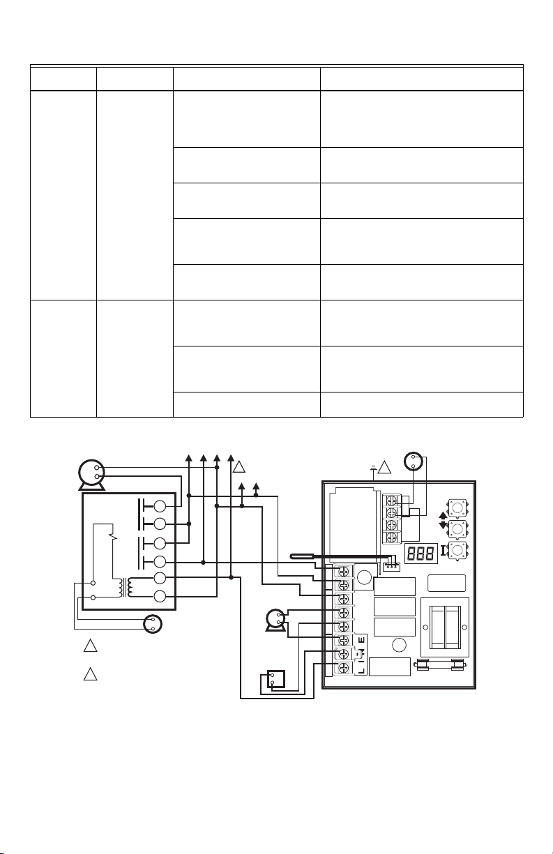
System
M27115
POWER SUPPLY. PROVIDE DISCONNECT
MEANS AND OVERLOAD
PROTECTION AS REQUIRED.
1
CONTROL CASE MUST BE CONNECTED
TO EARTH GROUND. USE GROUNDING
SCREW PROVIDED.
2
C1
B1
ZC
L2
LINE
C2
ZR
L1
B2
T
T3
2
1
SENSOR
LINE
VOLTAGE
CIRCULATOR
LINE
VOLTAGE
OIL BURNER
RELAY
2
LOW
VOLTAGE
THERMOSTAT
L7224
3
L1
(HOT)
L2
1
2
1
4
5
6
ZONE 2
LOW VOLTAGE
THERMOSTAT
R845A RELAY ZONE 2
ZONE 2
CIRCULATOR
TO ADDITIONAL R845A
RELAYS FOR OTHER ZONES
Condition
Boiler is hot,
house is cold.
Boiler is hot,
no hot potable
water.
L7224A,C; L7248A,C,L OIL ELECTRONIC AQUASTAT® CONTROLLERS
Table 11. Troubleshooting Guide
Diagnostic
Condition Check Action
Display is ON. 120 Vac at C1-C2 • 120 Vac at C1-C2, check wiring to pump.
Boiler below the Low Limit
temperature, wait for boiler to go
above Low Limit temperature.
Boiler above LL? If yes, check for
120 Vac between ZC and L2.
ELL setting (L7248L only) • Set ELL to Off for multizone system (see Fig.
Boiler above LL? If yes, check 120
Vac at ZR-L2 (only L7248L with
ELL set On)
Display is ON. Boiler Demand signal from the
water heater (either 120 Vac at
ZR-L2, or 0 Vac on T-T; depends
on installation and “duu” setting)
“duu” setting • Set duu to ON if 120 Vac water heater
Check DHW Module and DHW
Sensor
• Wiring OK, is pump running?
• If not, replace the pump.
• If pump is running, check for trapped air or
closed zone valves.
—
• If no 120 Vac, replace control.
• If yes, check zone relays, circulators and
wiring.
11).
• Set ELL to On for External Low Limit (see
Fig. 13).
• If no 120 Vac, check C1-C2 (see above).
• If yes, check the External Low Limit control.
• 24 Vac on T-T (or 0 Vac on ZR-L2), check
wiring to water heater
• Wiring OK, check the water heater
demand is connected to ZR
• Set duu to OFF if open/closed water heater
demand is connected to T-T
• DHW Module not properly connected and/or
DHW Sensor improperly positioned
Fig. 9. L7224A,C multizone system with circulator connections.
11 68-0281EFS—06
Page 12
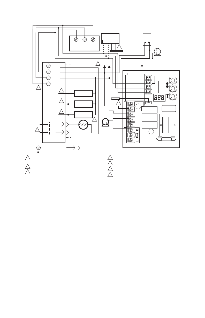
L7224A,C; L7248A,C,L OIL ELECTRONIC AQUASTAT® CONTROLLERS
M32025
POWER SUPPLY. PROVIDE DISCONNECT MEANS AND OVERLOAD
PROTECTION AS REQUIRED.
OPTIONAL FEATURE ON SELECT MODELS.
REFER TO DEVICE LABEL FOR WIRE COLOR CODE.
1
2
3
C1
B1
ZC
L2
LINE
C2
ZR
L1
B2
T
T
3
3
3
2
2
2
1
1
1
SENSOR
LINE
VOLTAGE
CIRCULATOR
L7224
3
4
3
3
5
BURNER
MOTOR
IGNITOR
VALV E
BURNER
MOTOR
IGNITOR
VALV E
CAD
CELL
JUNCTION
BOX
TO REMOTE
ALARM
CIRCUIT
ENVIRACOM™
TERMINAL
TH9421C
R7184
LIMIT
L1
L2
2
CAD
CELL
T
T
3
2
1
L1
(HOT)
L2
1
LEGEND SCREW TERMINAL 1/4 IN. (6 MM) QUICK CONNECT TERMINAL
SOLDERLESS WIRE CONNECTION
VALVE IS OPTIONAL ON SPECIFIED MODELS.
ENVIRACOM™ TERMINAL 3 IS ALSO THE FIRST THERMOSTAT TERMINAL.
OPTIONAL OUTDOOR RESET MODULE AND OUTDOOR SENSOR.
DUU MUST BE SET TO “ON” ON THE AQUASTAT.
4
5
6
1 2 3 OT OT
C7089U1006
OUTDOOR
SENSOR
6
50022037-002
OUTDOOR
RESET MODULE
7
INDIRECT
TANK
CIRCULATOR
LINE VOLTAGE
INDIRECT
TANK AQUASTAT
L2
7
Fig. 10. L7224A,C single zone system with circulator and indirect water tank with EnviraCOM™ thermostat.
68-0281EFS—06 12
Page 13
L7224A,C; L7248A,C,L OIL ELECTRONIC AQUASTAT® CONTROLLERS
M29655
POWER SUPPLY. PROVIDE DISCONNECT MEANS AND OVERLOAD PROTECTION
AS REQUIRED.
1
CONTROL CASE MUST BE CONNECTED TO EARTH GROUND. USE GROUNDING
SCREW PROVIDED.
2
3
L1
(HOT)
L2
1
2
1
4
5
6
ZONE 2
LOW VOLTAGE
THERMOSTAT
R845A RELAY ZONE 2
ZONE 2
CIRCULATOR
TO ADDITIONAL R845A
RELAYS FOR OTHER ZONES
C1
B1
ZC
L2
LINE
C2
ZR
L1
B2
T
T 3
2
1
SENSOR
LINE
VOLTAGE
CIRCULATOR
LINE
VOLTAGE
OIL BURNER
RELAY
2
LOW VOLTAGE
THERMOSTAT
L7248L
ELL=OFF
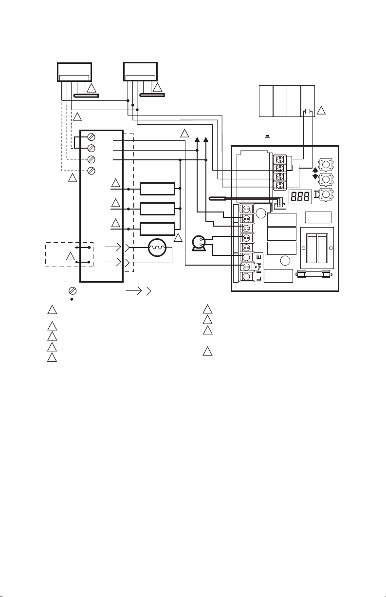
OPTIONAL OUTDOOR RESET MODULE AND OUTDOOR SENSOR.
ENVIRACOM TERMINALS.
OPTIONAL DOMESTIC HOT WATER MODULE AND TEMPERATURE SENSOR.
3
4
5
1 2 3 OT OT
C7089U1006
OUTDOOR
SENSOR
50022037-002 OUTDOOR
RESET MODULE
1 2 3 TS TS
50022037-005
DOMESTIC HOT
WATER MODULE
32003971-003
TEMPERATURE
SENSOR
4
ENVIRACOM
TERMINALS
3
5
Fig. 11. L7248L multizone system with circulator connections.
13 68-0281EFS—06
Page 14
L7224A,C; L7248A,C,L OIL ELECTRONIC AQUASTAT® CONTROLLERS
M32024
POWER SUPPLY. PROVIDE DISCONNECT MEANS AND OVERLOAD
PROTECTION AS REQUIRED.
OPTIONAL FEATURE ON SELECT MODELS.
REFER TO DEVICE LABEL FOR WIRE COLOR CODE.
VALVE IS OPTIONAL ON SPECIFIED MODELS.
ENVIRACOM™ TERMINAL 3 IS ALSO THE FIRST THERMOSTAT TERMINAL.
1
2
3
C1
B1
ZC
L2
LINE
C2
ZR
L1
B2
T
T
3
2
1
SENSOR
LINE
VOLTAGE
CIRCULATOR
L7224
3
4
3
3
5
BURNER
MOTOR
IGNITOR
VALV E
BURNER
MOTOR
IGNITOR
VALV E
CAD
CELL
JUNCTION
BOX
TO REMOTE
ALARM
CIRCUIT
ENVIRACOM™
TERMINAL
R7184
LIMIT
L1
L2
2
CAD
CELL
T
T
3
2
1
L1
(HOT)
L2
1
LEGEND SCREW TERMINAL 1/4 IN. (6 MM) QUICK CONNECT TERMINAL
SOLDERLESS WIRE CONNECTION
OPTIONAL OUTDOOR RESET MODULE AND OUTDOOR SENSOR.
OPTIONAL DOMESTIC HOT WATER MODULE.
WIRE ONLY THE ENVIRACOM TERMINALS (1, 2, 3) ON OIL PRIMARY
IF CONNECTING TO REMOTE DIAGNOSTICS, OTHERWISE CONNECT
A JUMPER BETWEEN THE TT TERMINALS.
ZONE PANEL TERMINALS MAY HAVE DIFFERENT LABEL. CHECK
PANEL MANUFACTURER SPECIFICATIONS FOR WIRING INSTRUCTIONS.
6
7
8
1 2 3 TS TS
32003971-003
TEMPERATURE
SENSOR
7
50022037-002
DOMESTIC HOT
WATER MODULE
9
MULTI-ZONE
RELAY PANEL
T T
4
5
1 2 3 OT OT
C7089U
OUTDOOR
SENSOR
6
50022037-002
OUTDOOR
RESET MODULE
8
9
applications).
Fig. 12. L7224/L7248 multizone system with Outdoor Reset and Domestic Hot Water Modules (indirect tank
68-0281EFS—06 14
Page 15
L7224A,C; L7248A,C,L OIL ELECTRONIC AQUASTAT® CONTROLLERS
M27113
POWER SUPPLY. PROVIDE DISCONNECT MEANS AND OVERLOAD
PROTECTION AS REQUIRED.
1
CONTROL CASE MUST BE CONNECTED TO EARTH GROUND.
USE GROUNDING SCREW PROVIDED.
2
W
L1 (HOT)
L2
1
B
R
C1
B1
ZC
L2
LINE
C2
ZR
L1
B2
T
T3
2
1
SENSOR
LINE
VOLTAGE
CIRCULATOR
LINE
VOLTAGE
OIL BURNER
RELAY
2
LOW
VOLTAGE
THERMOSTAT
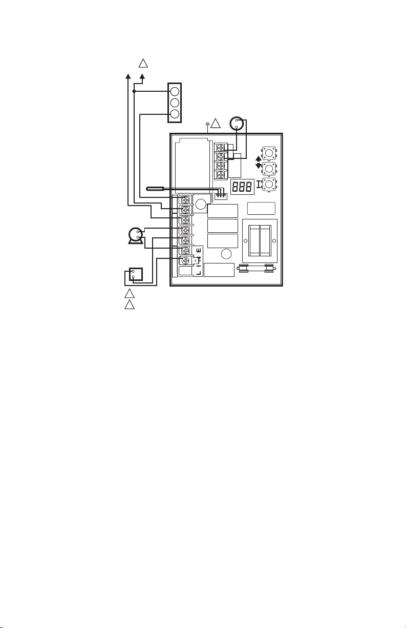
L7248L
ELL=ON
L6006
LOW LIMIT
CONTROLLER
Fig. 13. L7248L External Low Limit connections.
15 68-0281EFS—06
Page 16

L7224A,C; L7248A,C,L OIL ELECTRONIC AQUASTAT® CONTROLLERS
Automation and Control Solutions
Honeywell International Inc.
1985 Douglas Drive North
Golden Valley, MN 55422
customer.honeywell.com
® U.S. Registered Trademark
© 2012 Honeywell International Inc.
68-0281EFS—06 M.S. Rev. 09-12
Printed in United States
Page 17
Régulateurs à mazout Aquastat®
L7224A,C; L7248A,C,L
NOTICE D'INSTALLATION
APPLICATION
Les régulateurs électroniques à mazout Aquastat®
L7224A,C et L7248A,C,L conformes à la réglementation
2012 captent la température de façon électronique au
sein d'un limiteur homologué UL au moyen d'une seule
sonde de détection. Le L7248A,C et L7248A,C,L règle la
température des circulateurs, brûleurs au mazout et
chaudières. Le L7224/L7248 est un « dispositif à
réarmement d'extérieur » qui est activé lors du
branchement au nécessaire de réarmement d'extérieur
W8735S1000. Le réarmement d'extérieur effectué avec
le L7224/L7248 est conçu pour toutes les applications
excepté les systèmes de serpentin sans réservoir pour
eau chaude résidentielle. La conformité à la
réglementation 2012 du Ministère de l'énergie américain
(DOE) garantit une efficacité supérieure sans
interférence avec les exigences en matière d'eau chaude
domestique.
Le L7224A,C et le L7248A,C remplacent les régulateurs
L8124A, L8124C, L7124A,C, L7148A et L8148A. Les
régulateurs séries L7224A,C et L7248A,C,L fournissent
les informations sur le statut et le diagnostic sur
l'afficheur à cristaux liquides combinés à des voyants
DEL et à des thermostats compatibles EnviraCOM™ et
des outils diagnostiques pour améliorer les processus
diagnostiques.
Les régulateurs Aquastat L7224/L7248 sont destinés à
des applications résidentielles.
IMPORTANT
L'utilisation d'un dispositif à réarmement de la
température extérieure sur les systèmes à ser
pentin sans réservoir nécessitant un réglage
limite basse résultera en une réduction de l'effi
cacité du système.
CARACTÉRISTIQUES TECHNIQUES
Caractéristiques électriques :
Tension : 120 V c.a. 60 Hz
Alimentation : 7 VA maximum à 120 V c.a. plus charges
exter nes.
Thermostat courant : 100 mA nominaux à 24 V c.a.
Relais de brûleur :
Courant pleine charge à 7,4 A à 120 V c.a.;
Tension de rotor bloqué de 44,4 A à 1,2 A avec appel
à pleine charge;
Moins la charge d'allumage : 360 VA.
Relais de régulateur :
7,4 A à pleine charge à 120 V c.a.; 44,4 A à l'appel à
pleine charge.
Régulateur de zone (ZC) : 7,4 A à 120 V c.a. à pleine
charge;
44,4 A à l'appel à rotor bloqué.
REMARQUE : Toutes les charges combinées ne peuvent
Caractéristiques environnementales :
Température : -34 °C to +66 °C (-30 °F à 150 °F).
Humidité : 0 à 95 % d'humidité relative, sans condensa-
tion
Homologations :
Composants approuvés Underwriters Laboratories Inc.
Composants approuvés Canadian Underwriters Labora-
tories Inc.
-
-
pas dépasser 2000 VA.
Fonctionnement et conformité à la réglementation 2012 du
Ministère de l'énergie américain (DOE)
Le fonctionnement de ce régulateur peut retarder le fonctionnement du brûleur
pendant que la chaleur résiduelle circule hors de la chaudière.
REMARQUE : Ce fonctionnement peut différer des révisions Aquastat ® électroniques
antérieures qui n'utilisaient pas de purge thermique.
Page 18

RÉGULATEURS À MAZOUT AQUASTAT® L7224A,C; L7248A,C,L
AVERTISSEMENT
Accessoires :
Nécessaire de réarmement d'extérieur sans fil
W8735Y1000
Module de réarmement d'extérieur sans fil W873ER1000
Capteur de température extérieur sans fil C7089R1013
(requiert le W8735ER1000)
Nécessaire de réarmement d'extérieur AquaReset™
W8735S1000 (inclut le module de réarmement
d'extérieur 50022037-002 et le capteur de température
d'extérieur C7089U100)
Nécessaire d'eau chaude résidentiel AquaReset™
W8735S1008 (inclut le module d'eau chaude
résidentiel 50022037-005 et le capteur 32003971-003)
Module d'alarme EnviraCOM™ W8735S3000
C7089U1006 Capteur de température d'extérieur (utilisé
avec le 50022037-002)
32003971-003 Capteur de température (utilisé avec
50022037-005)
Capteur (Voir le Tableau 2).
14 000,485-016 1/4 po, diamètre (6,35 mm), 1 1/4 po
Fusible à cartouche en verre d'une longueur de (31,75
mm) 1 A, à action retardée.
120650 Composé thermoconducteur.
121371AA Capteur de pince de puits
Tableau 1. Puits pour régulateurs L7224A,C;
Numéro
de pièce
123869A 1/2 (12,7) NPT 3 (76,2) 1-1/2 (38,1)
123870A 3/4 (19,05) NPT 3 (76,2) 1-1/2 (38,1)
Tableau 2. Capteurs pour régulateurs L7224A,C et
Numéro de
pièce
50001464-001 12 (304,8) Commandes montées
50001464-003 24 (609,6) Commandes encastrées
50001464-004 36 (914,4)
50001464-005 48 (1219,2)
L7248A,C,L.
Taille d'orifice
po (mm)
L7248A,C,L.
Longueur
po (mm)
Insertion
po (mm)
Application
sur puits
Isolation po
(mm)
INSTALLATION
Lors de l'installation du produit...
1. Lire attentivement ces instructions. Le fait de ne pas
les suivre risque d'endommager le produit ou de
constituer un danger.
2. Vérifier les caractéristiques nominales indiquées
dans les instructions et sur le produit, et s'assurer
que celui-ci correspond bien à l'application prévue.
3. L'installateur doit être un technicien d'expérience
ayant reçu la formation pertinente.
4. Une fois l'installation terminée, vérifier le fonc-
tionnement du produit comme l'indiquent les
présentes instructions.
5. Placer la Limite haute, la Limite basse et le Différen-
tiel limite basse aux réglages recommandés par le
fabricant de la chaudière.
6. Inscrire le réglage Limite haute maximale du régula-
teur remplacé dans la zone de texte fournie sur
l'étiquette du couvercle à insert.
7. Inscrire le réglage Limite haute au moment de
l'installation dans la zone de texte fournie sur
l'étiquette du couvercle à insert.
Risque de choc électrique.
Peut provoquer des blessures graves, voire
mortelles ou des dommages à la propriété.
Débrancher l'alimentation en courant avant de
commencer l'installation pour prévenir des chocs
électriques ou des dommages matériels.
Montage
Les modèles L7224A,C et L7248A,C,L sont offerts à
montage en puits, en position horizontale, en position
verticale ou en montage encastré à distance du puits. Les
dimensions pour la variété d'options de montage sont
indiquées à la
d'une seule option de montage.
Fig. 1. Noter que chaque identité disposera
68-0281EFS—06 2
Page 19

Fig. 1. L7224A,C; L7248A,C,L dimensions de montage en po (mm).
M22147B
3/4
(75)
5-11/16
(145)
3/8
(10)
2-5/8 (67)
7-1/8
(181)
6-1/2
(166)
3-13/32 (86)
2x 1/4 (7) x 3/8 (9)
1/16 (2)
1-3/16
(30)
3-1/32
(77)
2-1/16 (53)
1-1/8 (29)
4-1/4 (109)
IMPORTANT
Le puits d'immersion doit être compatible avec
l'élément de détection et le capteur doit reposer
contre le bas du puits.
Nouvelle installation
Commander les ensembles de puits séparément;
consulter le
d'immersion et raccords de compression pour les
régulateurs de température. Les chaudières disposent
habituellement de deux prises qui permettent le montage
horizontal du puits pour que l'eau de la chaudière de
température moyenne puisse circuler librement sur le
puits.
1. Couper l'alimentation en courant et vidanger la
2. Si aucune prise n'est fournie, en ménager une à la
3. Recouvrir les filets du puits d'une petite quantité de
REMARQUE : Ne pas tenter de serrer en utilisant le boî-
4. Installer le puits sur la prise de la chaudière en ser-
5. Remplir de nouveau la chaudière et s'assurer de
6. Desserrer, mais ne pas retirer la vis de l'attache du
7. Installer le boîtier dans le puits de manière à ce que
8. Serrer fermement la vis de l'attache.
9. Insérer le capteur à élément jusqu'au fond du puits.
Tableau 1 et le formulaire n° 68-0040, Puits
chaudière, le cas échéant.
dimension et au filetage appropriés près du dessus
de la chaudière.
pâte à joint.
tier comme poignée.
rant fermement.
l'absence de fuites.
puits.
l'attache du boîtier glisse sur la bride du puits.
Consulter la section traitant de l'installation du
capteur de remplacement pour obtenir des détails.
(Au besoin, plier légèrement le fil à l'intérieur du boî
tier pour que le capteur reste au fond du puits.)
RÉGULATEURS À MAZOUT AQUASTAT® L7224A,C; L7248A,C,L
10. Mettre l'appareil en marche.
11. Placer la Limite haute, la Limite basse et le Différen-
tiel limite basse aux réglages recommandés par le
fabricant de la chaudière. (Consulter la section traitant du FONCTIONNEMENT.) (Consulter les
étapes 6 et 7 de la section traitant de l'INSTALLATION.)
12. Sur les modèles L7248L, régler l'option ELL de
manière à ce qu'elle soit compatible avec votre con
figuration (consulter la section traitant du FONCTIONNEMENT ainsi que les Fig. 11 et Fig. 13).
IMPORTANT
Le puits doit être bien ajusté dans le capteur
pour obtenir une meilleure réponse thermique.
Insérer le capteur jusqu'à ce qu'il repose au fond
du puits. Utiliser un puits d'une longueur appro
priée et plier le fil, au besoin, pour que le bulbe
reste au fond du puits.
Si le capteur n'épouse pas parfaitement la forme
du puits, utiliser le composé thermoconducteur
(fourni avec les modèles TRADELINE®) en
procédant comme suit : plier le sac de plastique
contenant le composé thermoconducteur sur le
sens de la longueur et l'enrouler doucement.
Couper ensuite l'extrémité du sac et la placer
tout au fond du puits. Tirer doucement sur le sac
pour le retirer du puits tout en le comprimant
fermement de manière à distribuer
uniformément le composé dans le puits. Plier le
fil, au besoin, pour que le capteur reste au fond
du puits et que la paroi externe du capteur reste
en contact avec la paroi interne du puits.
Consulter la
de l'extrémité extérieure du puits.
-
Fig. 2. Essuyer l'excès de composé
-
-
3 68-0281EFS—06
Page 20
RÉGULATEURS À MAZOUT AQUASTAT® L7224A,C; L7248A,C,L
CÂBLAGE DU CAPTEUR
MF22026
COMPOSÉ THERMOCONDUCTEUR
(EN OPTION)
CHAUDIÈRE
PUITS
D’IMMERSION
CAPTEUR
CÂBLAGE DU CAPTEUR
BOÎTIER DE RÉGULATEUR
CHAUDIÈRE
ATTACHE DU
PUITS D’IMMERSION
VIS DE L’ATTACHE
DU PUITS D’IMMERSION
PUITS
D’IMMERSION
COMPOSÉ THERMOCONDUCTEUR
(EN OPTION)
CAPTEUR
MF16120
Fig. 2. Position du capteur dans le puits d'immersion.
Remplacement de l'Aquastat, montage encastré
Couper l'alimentation et déposer l'ancien régulateur. Se
reporter à l'insert du couvercle de l'ancien régulateur pour
identifier et étiqueter tous les fils externes au fur et à mesure
de leur déconnexion. Si l'ancien puits ne convient pas au
nouveau montage, le déposer et le remplacer pas un puits
neuf approprié. Si l'ancien puits convient, il doit être utilisé.
Remplacement de l'Aquastat, montage sur puits
Couper l'alimentation et déposer l'ancien régulateur. Se
reporter à l'insert du couvercle de l'ancien régulateur pour
identifier et étiqueter tous les fils externes au fur et à
mesure de leur déconnexion. Si l'ancien puits ne convient
pas au nouveau montage, le déposer et suivre les
directives s'appliquant à la nouvelle installation. Si
l'ancien puits convient, il doit être utilisé.
1. Desserrer, mais ne pas retirer la vis de l'attache de
serrage du puits qui se trouve du côté du boîtier de
commande.
2. Prendre soin de bien placer l'attache du puits
d'immersion sur la bride de l'adaptateur et de serrer
sa vis.
3. Mettre le capteur à l'intérieur du puits comme
l'indique la
de l'installation du capteur de rechange.)
BORNES DE
THERMOSTAT
Fig. 2 ou 3. (Consulter la section traitant
AFFICHEUR
FUSIBLE
Fig. 4. Installation du capteur de rechange.
Installation du capteur de rechange
Couper l'alimentation et :
1. Débrancher prudemment le capteur de la carte de
circuit imprimé en tirant doucement sur le con
necteur.
2. Sortir doucement le capteur du puits thermomé-
trique et le passer dans la carte de circuit imprimé
en tirant sur les fils de connexion.
3. Aligner prudemment le capteur de remplacement
avec l'orifice de la carte de circuit imprimé et le
guider dans le boîtier Aquastat et le puits. (Con
sulter la Fig. 5.)
4. S'assurer que le capteur repose complètement au
fond du puits (consulter la
crayon pour mesurer la profondeur du capteur du
puits, au besoin.
5. Brancher le capteur dans la carte de circuit imprimé
en appuyant le connecteur du capteur dans un con
necteur homologue de la carte de circuit imprimé
(consulter la
6. Pour les capteurs à distance (régulateurs Aquastat
à montage encastré) s'assurer d'utiliser l'attache
121571AA (consulter la section traitant des acces
soires) pour maintenir le capteur fermement en
place.
Fig. 5).
BORNES DE
THERMOSTAT
T
T 3
2
1
Fig. 4). Utiliser un petit
BORNES
TM
ENVIRACOM
AFFICHEUR
-
-
-
-
2
1
T
T3
LINE
BORNES
ENVIRACOM
branchement du capteur et les orifices de puits pour
68-0281EFS—06 4
CONNECTEUR
TM
DE CAPTEUR
Fig. 3. Carte de circuit imprimé, montrant le
les modèles à montage horizontal.
L1
ZR
ORIFICES DU
CAPTEUR
L2
C2
ZC
MF32186
B1
B2
C1
ZR
L1
L2
C2
B2
C1
B1
ZC
connexion du capteur et les orifices de puits pour les
LINE
CONNECTEUR
DE CAPTEUR
RELAIS
ORIFICES DU CAPTEUR
FUSIBLE
MF32187
Fig. 5. Carte de circuit imprimé, indiquant la
modèles à montage vertical.
Page 21

RÉGULATEURS À MAZOUT AQUASTAT® L7224A,C; L7248A,C,L
AVERTISSEMENT
C1
B1
ZC
L2
LINE
C2
ZR
L1
B2
T
T
3
2
1
1 2 3 OT OT
C7089U1006
CAPTEUR D’EXTÉRIEUR
50022037-002
MODULE DE
RÉARMEMENT D’EXTÉRIEUR
1 2 3 TS TS
50022037-005
MODULE D’EAU
CHAUDE DOMESTIQUE
32003971-003
CAPTEUR DE
TEMPÉRATURE
MF29651
Fusible
Le fusible d’1 A situé près du transformateur est conçu
pour protéger le circuit EnviraCOM d’un câblage incorrect.
L’Aquastat continue de fonctionner si le fusible brûle ou
est retiré, bien qu'aucune communication EnviraCOM ne
sera possible sur le bus et Err 6 sera affiché. Voir le
Tableau 10.
CÂBLAGE
Risque de choc électrique.
Risque de causer des blessures graves, voire
mortelles.
Couper l'alimentation avant de raccorder le
câblage pour éviter les risques de choc électrique
ou l'endommagement de l'équipement.
Le câblage doit être conforme au code de l'électricité et
aux règlements locaux. Respecter les spécifications
énoncées dans la section Application lors du câblage de
ce régulateur. Utiliser un câble homologué pour une
température de 90 °C (194 °F).
IMPORTANT
Les bornes de ces régulateurs Aquastat sont
approuvées uniquement pour une utilisation
avec du câblage de cuivre.
Suivre les schémas de câblage appropriés illustrés à
l'intérieur du couvercle avant du L7224A,C; L7248A,C,L
ou dans la
Se reporter à la Fig. 6 pour savoir comment brancher le
module d'eau chaude domestique et le module de
réarmement d'extérieur (en option). Dans des schémas
de câblage subséquents ces modules seront affichés
avec une ligne pointillée indiquant qu'ils sont optionnels.
d'extérieur et du module d'eau chaude domestique.
Fig. 8-13.
Fig. 6. Raccordement du module de réarmement
FONCTIONNEMENT
Général
Les régulateurs électroniques à mazout Aquastat
L7224A,C et L7248A,C,L sont principalement des
limiteurs de sécurité conçus pour être utilisés avec des
chaudières à mazout dotées de brûleurs tension secteur
et de circulateurs. Plusieurs chaudières n'incluent pas le
câblage ni les compartiments de commande dans leur
conception, mais sont fournies avec un puits intégré
remplaçable qui sert d'accessoire de fixation aux
régulateurs Aquastat. Le câblage aux autres commandes
s'effectue par un conduit métallique souple.
Pour les chaudières qui n'incluent pas une commande à
distance intégrée, le câblage doit être complété par un
conduit ou acheminé derrière la feuille métallique de la
chaudière.
Une Haute limite électromécanique séparée n'est pas
requise dans un système qui utilise ce régulateur pour
répondre aux normes des Underwriters Laboratories Inc.
portant sur les chaudières de mazout (UL 726).
Sur les modèles L7224, la Limite haute, la Limite basse,
le Différentiel limite basse et la Temporisation anti-court
cycle peuvent être réglés au paramètre recommandé par
le fabricant de la chaudière. Sur les modèles L7248, la
Limite haute et la temporisation anti-court cycle peuvent
être réglés, voir « Réglages ».
La plage globale de Limite haute varie de 54 °C à 116 °C
(130 °F à 240 °F). Certains appareils peuvent utiliser des
plages différentes. Certains modèles peuvent avoir des
plages limitées pour la Limite haute du point de consigne,
cette plage limitée est indiquée sur l'étiquette de
l'appareil.
Certains modèles disposent également d'un réglage
Limite basse ou d'un Différentiel limite basse. La plage de
Limite basse varie de 43 °C à 104 °C (110 °F à 220 °F).
Certains appareils peuvent utiliser des plages différentes.
Le réglage Zr peut être réglé sur eau chaude domestique
(DHW), zonage ou applications avec serpentin sans
réservoir en fonction du L7224/L7248.
Si un module à réarmement d'extérieur W8735S1000
AquaReset™ est installé, la courbe de compensation
peut être réglée en entrant la température extérieure
minimale, la température minimale (chaudière) et une
température extérieure maximale composée de trois
chiffres. La plage de températures extérieures minimales
varie de -40 °C à 4,4 °C (-40 °F à 40 °F) et a un réglage
par défaut de -18 °C (0 °F). La plage de température
extérieure maximale varie de -1,1 °C à 21,1 °C (30 °F à
70 °F) 1,1 °C to 21,1 C) et a un réglage par défaut de
°F. La plage de températures minimales (eau ou
40
chaudière) varie entre 26,7 °C à 82,2 °C (80 °F à 180 °F
et a un réglage par défaut de 130 °F. Consulter les
directives d'installation « Module de réarmement
d'extérieur » (formulaire 69-2335) pour plus d'information
sur le réglage de la courbe de compensation de la
chaudière et tous les paramètres connexes.
Les modèles L7224A,C et L7248A,C,L sont conçus pour
être utilisés avec des thermostats électroniques et
électromécaniques de 24 V c.a. ou des thermostats
compatibles EnviraCOM™ et disposent de bornes à vis
qui permettent de se brancher facilement sur le terrain.
5 68-0281EFS—06
Page 22
RÉGULATEURS À MAZOUT AQUASTAT® L7224A,C; L7248A,C,L
Réglages
Pour empêcher la modification non autorisée des
réglages Aquastat, le mode de RÉGLAGE requiert de
suivre une procédure de saisie. Pour accéder au mode
RÉGLAGE, appuyer simultanément sur les touches
HAUT, BAS et l pendant trois secondes (se reporter à la
Fig. 5) pendant trois secondes. Appuyer sur la touche I
jusqu'à ce que la fonction à régler s'affiche :
Tableau 3. Caractéristiques réglables.
Display Definition
HL_ High Limit (Limite haute).
FP_ Protection contre le gel (Marche/Arrêt)
(L7248L uniquement)
Hdf High Limit Differential (Différentiel limite haute).
LL_ Low Limit (Limite basse). (L7224A, C)
Ldf Low Limit Differential (Différentiel limite basse).
(L7224A, C)
ELL External Low Limit (Limite basse externe).
(L7248L seulement)
duu Entrée ZR configurée comme demande d'eau
chaude domestique externe (MARCHE/ARRÊT)
(L7224A,C/L7248L)
ASC Anti Short-Cycle Timeout (La temporisation de
commande à temps de fonctionnement minimal)
(secondes); la fonction « ARRÊT » est
désactivée.
otL* Outdoor Temperature Low (Le paramètre de
température minimale extérieure pour la courbe
de compensation extérieure). °F ou °C
otH* Outdoor Temperature High (Le paramètre de
température maximale extérieure pour la courbe
de compensation extérieure). °F ou °C
btL* Boiler Temperature Low (Le paramètre de
température minimale de la chaudière pour la
courbe de compensation extérieure).
bP* Boost Period (Période de suralimentation)
(minutes). « ARRÊT » est affiché si
Suralimentation est inactif.
bS* Boost step (Étape de suralimentation indiquée
seulement si Suralimentation est activée; °F ou
°C; bp=MARCHE).
UUS* Warm Weather Shutdown Temperature
(Température d'arrêt par temps chaud; °F ou °C).
tPL** Température de limite de purge thermique
(°F ou °C), « ARRÊT » si désactivée
tPt** Délai de purge thermique (minutes), uniquement
affiché si tPL (limite de purge thermique) est
activé
PC Cycle de pompe (marche/arrêt)
F-C Unités de température (°F ou °C)
* Paramètres disponibles pour le réglage sur l'affichage à
trois chiffres seulement si le module de réarmement
d'extérieur AquaRest W8735S1000 est installé.
**Les réglages ne peuvent être modifiés que lorsque le
nécessaire de réarmement d'extérieur AquaReset
W8735S1000 n'est PAS installé.
Appuyer ensuite sur les touches HAUT (UP) et/ou BAS
(DOWN) pour déplacer le point de consigne à la valeur
désirée, pour déplacer le point de consigne à la valeur
désirée, pour passer de °F et °C, ou pour activer (ON) ou
désactiver (OFF) la limite basse externe. Après 60
secondes sans saisie de touches, le régulateur retournera
automatiquement au mode EXÉCUTION (RUN).
Afficheur
En mode EXÉCUTION (RUN), le régulateur Aquastat fera
apparaître «
suivi par la température (c.-à-d. 220) et par °F ou °C.
Pour lire les réglages de chaudière, appuyer sur la touche
I pour lire le paramètre d'intérêt. Par exemple, appuyer sur
I et la limite haute (HL) s'affichera, suivi par une valeur à
trois chiffres, c.-à-d. 220 suivi par °F ou °C. Le fait
d'appuyer de nouveau sur la touche I (sur les modèles
L7224) fera apparaître la valeur à trois chiffres et le
dénominateur de degré. Consulter Lecture de l'affichage,
Tableau 4.
Après environ 60 secondes sans appuyer sur une ou
plusieurs touches, l'affichage passera en mode
d'atténuation de l'affichage. Pour retourner au mode
d'affichage à grande brillance, appuyer simplement sur
une des touches.
bt » à l'écran (température de la chaudière)
68-0281EFS—06 6
Page 23
RÉGULATEURS À MAZOUT AQUASTAT® L7224A,C; L7248A,C,L
Tableau 4. Définitions de la lecture de l'affichage.
Tex t Description Display
Err Code d’erreur (en présence d’un code)
bT Température de la chaudière
HL
HdF Différentiel limite haute
LL Limite basse (L7224 seulement)
Ldf Différentiel limite basse (L7224 seulement)
tt État du thermostat local
ttE État du thermostat EnviraCOM
brn Sortie B1 (brûleur) (MARCHE ou ARRÊT)
Cir Sortie C1 (circulateur) (MARCHE ou ARRÊT)
ZC Sortie ZC (commande de zone)
Zr Appel ZR (demande de zone) de CHALEUR
ELL Limite basse externe activée
duu ZR configurée comme demande d’eau chaude
ASC Temporisation anti-court cycle
bSP
dhc
ot
otL
otH
btL
bP
bS
UUS
1
Le paramètre local s’affiche; non pas le paramètre modifié par
un régulateur externe enviracom.
2
Les paramètres peuvent seulement être affichés si le module
de réarmement d’extérieur et le capteur de températuresont
installés et fonctionnent correctement.
3
Les paramètres peuvent seulement être affichés si le module
d’eau chaude domestique et le capteur sont installés et fonc
tionnent correctement.
1
Limite haute
(MARCHE ou ARRÊT)
(MARCHE ou ARRÊT)
(L7248L seulement)
domestique (L7224, L7248 seulement)
Point de consigne de la chaudière
Module d’eau chaude domestique branché 3
(OUI ou NON)
Température extérieure
Basse température extérieure
Haute température extérieure
Basse température de chaudière
Période de suralimentation
Étape de suralimentation
Température d’arrêt par temps chaud
2
2
2
2
2
2
2
2
Fonctionnement
Les modèles L7224 et L7248 peuvent se trouver dans un
des quatre états de fonctionnement suivants : Normal,
Limite haute, Limite basse et Erreur. S'il fonctionne
normalement, le régulateur alterne entre la Limite haute,
le Mode normal et la Limite basse. Seuls les appareils
possédant des réglages haute limite sont limités aux états
Haute limite et Normal. Par contre, le régulateur passera
à l'état Erreur en présence d'une situation anormale.
États de fonctionnement :
1. Normal : La température de la chaudière est
passée sous le réglage Limite haute (moins le
différentiel) et n'a pas dépassé le réglage Limite
haute; ou, la température de la chaudière est
passée au-dessus du réglage Limite basse et n'a
pas chuté sous le réglage Limite basse (moins le
différentiel); ou l'entrée ZR n'est pas alimentée par
une tension de 120 V c.a. (seulement L7248L avec
l'ELL placé à Marche).
2. High Limit (Limite haute) : La température de la
chaudière a dépassé le réglage Limite haute et n'a
pas chuté sous le réglage Limite haute (moins le
différentiel).
3. Low Limit (Limite basse) : La température de la
chaudière est passée sous le réglage Limite basse
(moins le différentiel limite basse) et n'a pas
dépassé le réglage Limite basse; ou l'entrée ZR est
alimentée par une tension de 120 V c.a. (seulement
L7248L avec l'ELL réglé à Marche).
4. Error (Erreur) : Une erreur a été détectée par le
régulateur (p. ex. capteur ouvert) et a coupé la sor
tie du brûleur. La sortie ZC est activée. Le régulateur continue de surveiller le système et redémarre
automatiquement si l'erreur disparaît. Se reporter
Tableau 7.
au
La séquence de fonctionnement des modèles L7224/
L7248 est illustrée dans les
Tableau 6 à 9.
Régulateur Limite haute
La Limite haute ouvre et coupe le circuit du brûleur
lorsque la température augmente jusqu'au point de
consigne. La Limite haute se remet automatiquement en
circuit lorsque la température de l'eau chute sous le point
de consigne et par l'intermédiaire du différentiel. Le
Différentiel limite haute des modèles L7248 est préréglé à
8 °C (15 °F). Le Différentiel limite haute des modèles
L7224 est préréglé à 6 °C (10 °F).
Régulateur de Limite basse et de circulateur
Lorsque la température monte et que le réglage du
différentiel est placé par défaut à 6 °C (10° F), le circuit du
brûleur est coupé et le circuit du circulateur utilise le point
de consigne Basse limite (en l'absence de demande de
chaleur). Lorsque la température chute de 6 °C (10 °F)
sous le point de consigne Limite basse, le circuit du
-
brûleur se déclenche et le circuit du circulateur se coupe.
Fig. 7.
Voir la
-
7 68-0281EFS—06
Page 24
RÉGULATEURS À MAZOUT AQUASTAT® L7224A,C; L7248A,C,L
Lorsque la température de la chaudière tombe en
L’INTERRUPTEUR S’OUVRE
LORSQUE LA TEMPÉRATURE
MONTE. LE BRÛLEUR S’ÉTEINT.
LE CIRCULATEUR FONCTIONNE
RÉGLAGE
LIMITE
HAUTE
RÉGLAGE
LIMITE
BASSE
LORSQUE L’EAU ATTEINT LE RÉGLAGE LIMITE BASSE, LE BRÛLEUR SE
1
COUPE OU LA POMPE DE CIRCULATEUR DÉMARRE
(LORS D’UNE DEMANDE DE CHALEUR).
L7224 : 6 °C (10 °F)
DIFFÉRENCE
L7248 : 8 °C (15 °F)
DIFFÉRENCE
6 ºC (10 ºF)
DIFFÉRENCE
LORS D’UNE DEMANDE
DE CHALEUR.
L’INTERRUPTEUR S’ACTIVE
LORS D’UNE CHUTE DE
TEMPÉRATURE. LE BRÛLEUR
FONCTIONNE LORS D’UNE
DEMANDE DE CHALEUR.
EN L’ABSENCE DE DEMANDE DE
CHALEUR, L’INTERRUPTEUR
S’ACTIVE LORS D’UNE HAUSSE
DE TEMPÉRATURE.
L’INTERRUPTEUR S’ACTIVE LORS
D’UNE CHUTE DE TEMPÉRATURE,
LE BRÛLEUR EST ALLUMÉ POUR
MAINTENIR UNE TEMPÉRATURE
D’EAU MINIMALE. LE
CIRCULATEUR EST DÉSACTIVÉ.
1
MF23364
Fig. 7. Points de consigne et différentiels.
Fonction Anti-court cycle
La fonction Anti-court cycle permet de sélectionner sur
site un délai de temporisation entre les cycles de brûleur.
Si une demande de chaleur est faite après la fin du cycle
de chaleur précédent et avant l'expiration de la
temporisation de l'Anti-court cycle, le circulateur pourra
fonctionner, mais le brûleur sera coupé jusqu'à ce que le
délai soit expiré. La plage de temporisation anti-court
cycle varie de la position OFF (arrêt) à 5 minutes.
REMARQUE : Cette fonction est bloquée lorsqu'il y a une
REMARQUE : Lorsque l'Aquastat est branché au régula-
demande d'eau chaude domestique. Les
demandes d'eau chaude domestique sont
traitées immédiatement, sans délai.
teur primaire et/ou au thermostat par
l'intermédiaire du bus EnviraCOM, la
durée de l'Anti-court cycle ne s'applique
pas aux événements de recyclage comme
une perte d'écoulement d'air ou de
flammes. Il s'applique seulement à la perte
de demande.
dessous de la limite de température de protection contre
le gel (fixée à 40
Les sorties Circulateur et ZC sont les mêmes qu'avant
que la fonction de protection contre le gel n'ait été activée.
Elles peuvent être sur Marche ou Arrêt durant le cycle de
protection contre le gel.
Lorsque la température de la chaudière atteint la limite de
température de protection contre le gel plus un différentiel
de 10
rester allumé en raison d'une autre demande.
Fonctionnement de la purge thermique
La fonction de la purge thermique est d'assurer qu'une
chaleur résiduelle utilisable circule dans la chaudière
jusqu'à ce qu'elle soit suffisamment évacuée du système
avant que le brûleur ne puisse s'allumer. À cette fin, sur
l'appel de chauffage, le brûleur ne s'allume pas pendant
que le circulateur tourne jusqu'à ce que la température de
la chaudière tombe en deçà de la température de purge
thermique ou jusqu'à ce que le délai ait pris fin. Ces deux
paramètres peuvent être modifiés. Lorsque la
température de la chaudière atteint la température de
purge thermique, le brûleur peut s'allumer. La purge
thermique n'est appliquée que sur les modèles Aquastat
avec démarrage à froid (L7248) et n'interfère pas avec les
demandes en eau chaude domestique ou les chauffe-eau
équipés d'accessoires à réarmement extérieur de
Honeywell. Pour les modèles à démarrage à chaud où
une limite basse doit être définie, la purge thermique n'est
pas appliquée.
En plus des paramètres de température et de délai de
purge thermique, deux autres conditions annulent la
purge thermique de l’Aquastat pour maintenir le confort
de l’espace :
• La température de la chaudière a chuté de 10 °F
depuis le début de la purge thermique.
• La température de la chaudière refroidit à un taux
supérieur à 5
en marche.
La fonction de purge thermique est disponible pour les
applications à zone unique ainsi qu'à plusieurs zones.
Réglages de la purge thermique
ZR - Demande d'eau chaude domestique
La borne ZR peut être sélectionnée pour répondre à une
demande indirecte du chauffe-eau. Ce paramètre est
réglé par l'intermédiaire d'un affichage à trois chiffres (voir
la section du présent document traitant des réglages).
Une demande de chaleur faite par l'intermédiaire de la
borne ZR a priorité sur d'autres fonctions comme la
fonction Anti-court cycle ou celles activées par le module
de réarmement d'extérieur (consulter le formulaire no 692335EFS pour obtenir de plus amples renseignements).
Protection contre le gel
La fonction de protection contre le gel protège la
chaudière et potentiellement ses conduits de dommages
pouvant avoir lieu lorsque l’eau dans le système
commence à geler. La fonction de protection contre le gel
est uniquement activée sur le modèle L7248 (modèles
avec démarrage à froid). Le réglage par défaut est activé
(marche) mais peut être désactivé en utilisant l’afficheur à
3 chiffres. Voir le
68-0281EFS—06 8
Tableau 3.
Certains paramètres de purge thermique sont
configurables avec l’afficheur à trois chiffres. Voir
Réglages » à la page 6. La purge thermique peut être
«
désactivée en réglant la limite de température de purge
thermique sur Arrêt.
Purge thermique et eau chaude domestique
La fonction de purge thermique est automatiquement
désactivée en cas d'appel d'eau chaude domestique de la
borne Zr pour garantir que de l’eau chaude est disponible
en temps voulu. Consulter «
domestique
Cycle de la pompe
La fonction de cycle de la pompe actionne la pompe du
système pendant 15 secondes après une période de cinq
jours non réglable sans aucune activité de la pompe. Le
réglage par défaut de la fonction de cycle de la pompe est
activé (marche) mais peut être désactivé (arrêt) en
utilisant l’afficheur à 3 chiffres. Voir le
°F), le brûleur se met en marche forcée.
°F fixe, le brûleur s’éteint à moins qu'il ne doive
°F/minutes pendant que le circulateur est
» à la page 8.
ZR - Demande d’eau chaude
Tableau 3.
Page 25
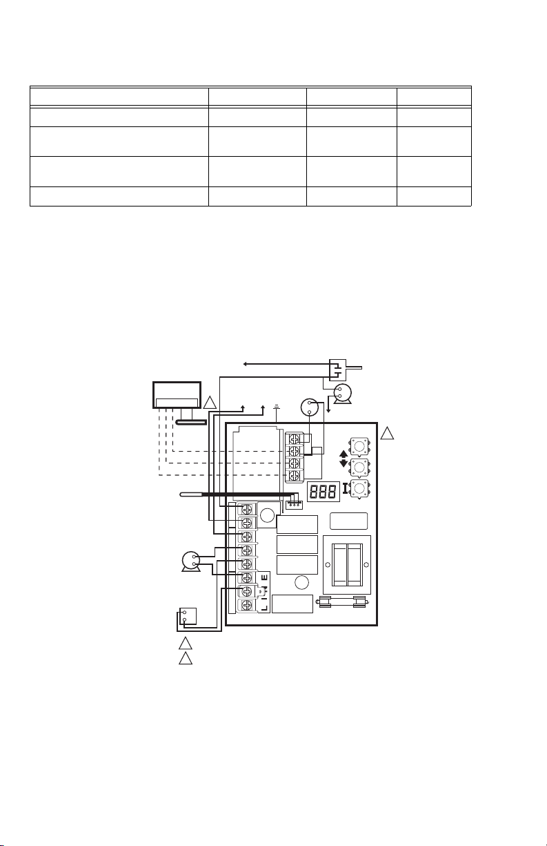
RÉGULATEURS À MAZOUT AQUASTAT® L7224A,C; L7248A,C,L
Tableau 5. Réglages de la purge thermique.
Nom du paramètre Valeur minimale Valeur maximale Défaut
Chute de la température de la chaudière Non réglable Non réglable 10 °F
Limite de température de purge
thermique
Taux de chute de température de purge
thermique
120 °F (ou Arrêt) 160 °F 140 °F (L7248)
Non réglable Non réglable 5 °F/minute
Délai de purge thermique 1 minute 10 minutes 2 minutes
VÉRIFICATION
Mettre le système en marche et observer au moins un
cycle complet pour s'assurer que le régulateur fonctionne
correctement. Consulter la section DÉPANNAGE pour
utiliser des DEL pour vous aider à vérifier le
fonctionnement du système.
MODULE DE RÉARMEMENT
D’EXTÉRIEUR
50022037-002
1 2 3 OT OT
CAPTEUR
D’EXTÉRIEUR
C7089U1006
CAPTEUR
CIRCULATEUR
(TENSION
SECTEUR)
TENSION
SECTEUR,
RELAIS DU
BRÛLEUR
À MAZOUT
(SOUS TENSION)
TENSION)
1
ZR
L1
L2
C2
B2
C1
B1
ZC
L1
(SOUS
L1
DÉPANNAGE
Lors de la tentative de diagnostic de la performance du
système, la référence de l'affichage DEL peut vous aider
à identifier les secteurs spécifiques qui ne fonctionnent
pas. Le message Err défilera dans l'affichage DEL suivi
d'un chiffre (1-8). Se reporter aux
obtenir une description de chaque erreur et des actions
suggérées.
AQUASTAT DE RÉSERVOIR
INDIRECT TENSION SECTEUR
CIRCULATEUR
L2
T
T3
LINE
DE RÉSERVOIR
INDIRECT
L2
2
1
Tableau 10 et 11 pour
2
MODULE DE RÉARMEMENT D’EXTÉRIEUR (EN OPTION).
1
2
POUR UNE MEILLEURE PERFORMANCE, RÉGLER DUU= ON (MARCHE).
Fig. 8. Système à zone de chauffage unique avec circulateurs et réservoir d'eau indirect L7224A,C; L7248L.
Module de réarmement d'extérieur facultatif.
9 68-0281EFS—06
MF32023
Page 26

RÉGULATEURS À MAZOUT AQUASTAT® L7224A,C; L7248A,C,L
Table 6. L7224/L7248 séquence de fonctionnement du régulateur.
Action Réponse système
Le thermostat fait une demande de chaleur. Le circulateur se met en marche lorsque la température de l'eau est
La température de la chaudière dépasse la
Limite haute.
supérieure au réglage limite basse (le cas échéant) ou supérieur à la
limite de température de purge thermique (tPL) si la purge thermique
est activée. La température de la chaudière est vérifiée. Le brûleur se
met en marche lorsque la température de l'eau est inférieure au
réglage limite haute moins le différentiel ou égale ou inférieure à la
limite de température de purge thermique (tPL) pour les chaudières à
démarrage à froid si la limite de température de purge thermique est
activée. Si tPL est activée, le brûleur peut également se mettre en
marche si la température de la chaudière refroidit à 10
minute ou si le délai de purge thermique (tPt) a expiré.
Si la fonction Temporisation anti-court cycle est activée, le brûleur ne
démarre pas avant que la Temporisation anti-court cycle entre les
cycles expire une fois la demande en chaleur satisfaite.
Le brûleur est éteint. Le brûleur redémarre lorsque la température de
l'eau chute sous le réglage Limite haute moins le différentiel. Si la
purge thermique est activée, le brûleur est allumé lorsque la limite de
température de purge thermique est atteinte, le délai de purge
thermique a expiré ou le taux de refroidissement de la température de
la chaudière dépasse 10
°F/minute.
°F ou plus par
Le thermostat est satisfait. Le circulateur et le brûleur s'éteignent.
La température de la chaudière chute sous le
réglage de Limite basse moins le différentiel
(si applicable).
Situation d'erreur 1-5. Si une situation d'erreur est détectée, toutes les sorties, sauf la sortie
Le brûleur est allumé, le circulateur est éteint. Le brûleur cesse de
fonctionner lorsque la température de l'eau dépasse le réglage Limite
basse. Le courant à la borne Zc est coupé..
ZC, sont coupées.
Le brûleur est éteint. La commande continue de fonctionner et
redémarre une fois l'erreur corrigée.
Durant la séquence de vérification des erreurs, le système s'assure de
l'absence de dérive dans le capteur et de corrosion dans les
connexions.
Situation d'erreur 6. La communication EnviraCOM n'est pas disponible.
Situation d'erreur 7. Le régulateur a réinitialisé les réglages Limite haute, Limite basse et
Situation d'erreur 8. Si la situation d'erreur est détectée, toutes les sorties, sauf la sortie ZC,
Situation d'erreur 9*. Le système continue de fonctionner sans fonctionnalité de réarmement
Situation d'erreur 10*. Le système continue de fonctionner en utilisant les paramètres de
Situation d'erreur 11*. Le système continue de fonctionner avec la température de chaudière
Différentiel à une valeur par défaut et continuera d'utiliser ces réglages
pendant le fonctionnement.
La performance du système sera dégradée.
sont coupées. Le brûleur est éteint. Le régulateur continue de
fonctionner et redémarre lorsque les trois touches utilisateur sont
enfoncées pendant plus de 60 secondes.
d'extérieur
réarmement d'extérieur activés lors de la programmation. Le code
d'erreur s'efface automatiquement.
réglée à Limite haute.
* Situation d'erreur seulement disponible lorsque le module de réarmement d'extérieur est installé.
68-0281EFS—06 10
Page 27

RÉGULATEURS À MAZOUT AQUASTAT® L7224A,C; L7248A,C,L
Table 7. L7224/L7248 séquence de fonctionnement du régulateur avec des zones multiples branchées par
l'intermédiaire de la borne ZR.
Action Réponse du système
La borne de demande de zone (ZR) est
branchée au L1 (demande de chaleur par la
zone).
La température de la chaudière dépasse la
Limite haute.
L'entrée Demande de zone est désactivée (les
zones sont satisfaites).
La température de la chaudière chute sous le
réglage Limite basse moins le différentiel (le
cas échéant).
La température de la chaudière est vérifiée. Le brûleur se met en
marche lorsque la température de l'eau est inférieure au réglage limite
haute ou égale ou inférieure à la limite de température de purge
thermique (tPL) pour les chaudières à démarrage à froid si la limite de
température de purge thermique est activée. Si tPL est activée, le
brûleur peut également se mettre en marche si la température de la
chaudière refroidit à 10
thermique (tPt) a expiré. La Temporisation anti-cycle court est utilisée,
consulter le
Le brûleur est éteint. Le brûleur redémarre lorsque la température de
l'eau chute sous le réglage Limite haute moins le différentiel. Si la
purge thermique est activée, le brûleur est allumé lorsque la limite de
température de purge thermique est atteinte, le délai de purge
thermique a expiré ou le taux de refroidissement de la température de
la chaudière dépasse 10 °F/minute.
Tableau 6.
°F ou plus par minute ou si le délai de purge
Le brûleur s'éteint.
Le brûleur s'allume et le régulateur de zone est désactivé. Le brûleur
s'éteint et le régulateur de zone se réactive lorsque la température de
l'eau dépasse le réglage Limite basse.
.
Table 8. Séquence de fonctionnement du régulateur avec l'appareil Basse limite externe branché par l'intermé-
diaire de la borne ZR.
Action Réponse du système
La borne de demande de zone (ZR) est
branchée au L1 (demande de chaleur par la
Limite basse externe).
La température de la chaudière dépasse la
Limite haute.
L'entrée Demande de zone est désactivée (la
Limite basse externe est satisfaite).
La température de la chaudière est vérifiée. Le brûleur démarre
lorsque la température de l'eau chute sous le réglage Limite haute. Le
circulateur s'éteint.
Le brûleur est éteint. Le brûleur redémarre lorsque la température de
l'eau chute sous le réglage Limite haute moins le différentiel.
Le brûleur est éteint.
Table 9. L7224, séquence de fonctionnement du régulateur avec l'eau chaude domestique branchée par l'inter-
médiaire de la borne ZR.
Action Réponse du système
La borne Demande de zone (ZR) est
branchée à L1 (demande de chaleur pour
l'eau chaude domestique).
La température de la chaudière dépasse la
Limite haute.
L'entrée Demande de zone est désactivée (la
demande en eau chaude domestique est
satisfaite).
La température de la chaudière est vérifiée. Le brûleur démarre
lorsque la température de l'eau chute sous le réglage Limite haute.
Le brûleur est éteint. Le brûleur redémarre lorsque la température de
l'eau chute sous le réglage Limite haute moins le différentiel.
Le brûleur est éteint.
11 68-0281EFS—06
Page 28

RÉGULATEURS À MAZOUT AQUASTAT® L7224A,C; L7248A,C,L
Table 10. Codes d'erreur DEL.
Code
d'erreur
Aquastat
Cause/Action
Alarme
EnviraCOM™
Err1 Défaillance du capteur Aquastat; vérifier le capteur d'eau. 18
Err2 Défaillance ECOM; vérifier le câblage EnviraCOM™. 18
Err3 Interférences électriques excessives ou fréquence hors plage. Défaillance du matériel;
remplacer le régulateur.
18, 58
Err4 Défaillance B1; vérifier le câblage B1/la tension. 64
Err5 Basse tension; vérifier L1-L2, 110 V c.a. 59
a
Err6
Avertissement : Fusible; vérifier les fils ECOM; remplacer le fusible. 92
Err7 Avertissement : EEPROM, HL, LL, Hdf, Ldf; réinitialisation aux valeurs par défaut. N/A
b
Err 8
Err9
Err 10
Err 11
a
Des avertissements sont générés pour indiquer que le système ne fonctionne pas de manière optimale; l'Aquastat
continue néanmoins de fonctionner et de maintenir la température de la chaudière. Dans l'éventualité où un module
de réarmement d'extérieur serait utilisé, les avertissements peuvent indiquer une situation d'erreur relative au réglage
de la courbe de compensation, un fonctionnement non optimal de plusieurs fonctions, une utilisation des réglages par
défaut de l'Aquastat ou une non exécution des algorithmes de réarmement d'extérieur. Les avertissements sont effa
cés une fois le(les) problème(s) résolu(s).
b
Pour effacer le code d'erreur Err 8, appuyer simultanément sur les trois touches utilisateur et les maintenir enfoncées
pendant 60 secondes. Le code d'erreur Err 8 s'efface et l'affichage retourne à la normale. Le code d'erreur Err 8 sert
à déceler les relais soudés sur l'Aquastat et n'affiche habituellement qu'à la fin de la durée de vie du régulateur. Si le
code d'erreur Err 8 s'affiche prématurément (avec des régulateurs pratiquement neufs), s'assurer de vérifier la réac
tion de tension au B1 lorsque le B1 devrait être coupé, puis de vérifier l'appel de courant à la borne b pour vous
assurer que le brûleur à mazout ne consomme pas trop de courant. Le code d'erreur Err 8 continuera de s'afficher si
la défaillance B1 n'est pas effacée.
Défaillance B1 répétée (tension présente à B1 lorsque l'entrée est désactivée); vérifier le
câblage/la tension à B1.
a
Avertissement : Défaillance du système de réarmement d'extérieur; communication
perdue au module de réarmement d'extérieur, Défaillance du module de réarmement
d'extérieur, détection de plusieurs capteurs de température extérieure sur le bus, ou
défaillance du capteur de température extérieure. Vérifier le câblage EnviraCOM (1,2,3),
vérifier le câblage du capteur.
a
Avertissement : Défaillance de la suralimentation; mode de suralimentation actif au
moins une fois par cycle pour les 60 derniers cycles consécutifs. Vérifier les réglages de
la courbe de compensation extérieure.
a
Défaillance du module d'eau chaude domestique/capteur; communication perdue vers le
module d'eau chaude domestique, défaillance du module d'eau chaude domestique ou
défaillance du capteur de température. Vérifier le câblage EnviraCOM (1,2,3), vérifier le
câblage du capteur.
25
50, 53, 149
150
146, 147, 148
-
-
Table 11. Guide de dépannage.
Condition du
système
La chaudière
est froide, la
maison est
froide.
Condition liée
au diagnostic
L'afficheur est
ÉTEINT.
L'afficheur est
ALLUMÉ.
Vérifier Action
Alimentation du système, 100 V
c.a.
24 V c.a. T-T Absence de 24 V; remplacer le régulateur.
Présence de 24 V; débrancher le
thermostat, court-circuit au T-T.
120 V c.a. à B1-B2 • Dans la négative, remplacer le régulateur.
Se reporter à Err sur l'afficheur. —
68-0281EFS—06 12
Mettre le système en marche.
La chaudière démarre, vérifier le câblage et le
thermostat.
• Dans l'affirmative, vérifier le brûleur et le
câblage.
Page 29

Condition du
système
La chaudière
est chaude, la
maison est
froide.
La chaudière
est chaude,
sans eau
chaude
potable.
RÉGULATEURS À MAZOUT AQUASTAT® L7224A,C; L7248A,C,L
Table 11. Guide de dépannage.
Condition liée
au diagnostic Vérifier Action
L'afficheur est
ALLUMÉ.
L'afficheur est
ALLUMÉ.
120 V c.a. à C1-C2 • 120 V c.a. à C1-C2, vérifier le câblage vers la
La chaudière se trouve sous la
température Limite basse,
attendre que la chaudière se
trouve au-dessus de la
température Limite basse.
Chaudière au-dessus de la LL
(Limite basse)? Dans l'affirmative,
s'assurer que la tension est de
120 V c.a. entre le ZC et le L2.
Réglages ELL (L7248L
seulement)
Chaudière au-dessus de LL?
Dans l'affirmative, s'assurer que la
tension est de 120
Signal de demande de la
chaudière provenant du chauffeeau (120 V c.a. à ZR-L2 ou
V c.a. sur T-T; dépend de
0
l’installation et du réglage « duu »)
Réglage « duu » • Régler duu sur Marche si la demande 120 V
Vérifier le module et le capteur
d'eau chaude domestique
pompe.
• Le câblage est en bon état, la pompe
fonctionne-t-elle?
• Dans la négative, remplacer la pompe.
• Si la pompe fonctionne, s'assurer de
l'absence d'air emprisonnée ou de vannes
de zone fermées.
—
• En l'absence d'une tension de 120 V c.a.,
remplacer le régulateur.
• Dans l'affirmative, vérifier les relais de zone,
les circulateurs et le câblage.
• Régler l'ELL à Arrêt pour le système
multizones (voir la
• Régler l'ELL à Marche pour la Limite basse
exter ne (voir la
• En l'absence d'une tension de 120 V c.a.,
vérifier C1-C2 (voir au-dessus)
• Dans l'affirmative, vérifier la régulateur Limite
basse externe.
• 24 V c.a. sur T-T (ou 0 V c.a. sur ZR-L2),
vérifier le câblage au chauffe-eau
• Câblage OK, vérifier le chauffe-eau
c.a. du chauffe-eau est connectée à ZR
• Régler duu sur Arrêt si la demande ouvert/
fermé du chauffe-eau est connectée à T-T
• Le module d'eau chaude domestique est mal
branché et/ou le capteur est mal positionné
Fig. 11).
Fig. 13).
13 68-0281EFS—06
Page 30

RÉGULATEURS À MAZOUT AQUASTAT® L7224A,C; L7248A,C,L
MF27115
1
2
C1
B1
ZC
L2
LINE
C2
ZR
L1
B2
T
T3
2
1
2
L7224
3
L2
1
2
1
4
5
6
ALIMENTATION. FOURNIR AU BESOIN UN
DISPOSITIF DE COUPURE ET UNE
PROTECTION CONTRE LES SURCHARGES.
LE BOÎTIER DE COMMANDE DOIT ÊTRE
BRANCHÉ À LA MASSE DE TERRE.
UTILISER LA VIS DE MISE À LA TERRE
FOURNIE.
CIRCULATEUR
(TENSION
SECTEUR)
TENSION
SECTEUR,
RELAIS DU
BRÛLEUR À
MAZOUT
THERMOSTAT
BASSE TENSION
ZONE 2
CAPTEUR
L1
(CHAUD)
R845A RELAIS ZONE 2
CIRCULATEUR
ZONE 2
VERS LES RELAIS R845A
ADDITIONNELS POUR D’AUTRES ZONES
THERMOSTAT
BASSE
TENSION
Fig. 9. L7224A,C système multizones avec connexions du circulateur.
68-0281EFS—06 14
Page 31

RÉGULATEURS À MAZOUT AQUASTAT® L7224A,C; L7248A,C,L
3
TH9421C
R7184
T
LIMIT
T
L1
3
L2
2
1
5
BORNE
ENVIRACOM™
VERS LE
CIRCUIT DE
2
L’ALARME
À DISTANCE
LÉGENDE BORNE À VIS
CONNEXION DE FIL SANS SOUDURE
1
ALIMENTATION. ASSURER AU BESOIN UN DISPOSITIF DE COUPURE ET
UNE PROTECTION CONTRE LES SURCHARGES.
FONCTION EN OPTION SUR DES MODÈLES SÉLECTIONNÉS.
2
3
SE REPORTER À L’ÉTIQUETTE DE L’APPAREIL POUR CONNAÎTRE LE
CODE DE COULEUR DE FIL.
MOTEUR DE
BRÛLEUR
ALLUMEUR
VANNE
CELLULE AU
CADMIUM
3
3
3
MOTEUR DE
BRÛLEUR
ALLUMEUR
CELLULE
AU CADMIUM
BOÎTIER DE
RACCORDEMENT
1
2
(SOUS TENSION)
1
VANNE
4
BORNE DE CONNEXION
RAPIDE 6 MM (1/4 PO)
MODULE DE RÉARMEMENT
D’EXTÉRIEUR
50022037-002
1 2 3 OT OT
L1
2
3
L2
CAPTEUR
CIRCULATEUR
(TENSION
SECTEUR)
4
LA VANNE EST OPTIONNELLE POUR LES MODÈLES SPÉCIFIÉS.
5
LA BORNE ENVIRACOM™ 3 EST ÉGALEMENT LA PREMIÈRE BORNE DU THERMOSTAT.
6
CAPTEUR D’EXTÉRIEUR ET MODULE DE RÉARMEMENT D’EXTÉRIEUR EN OPTION.
DUU DOIT ÊTRE RÉGLÉ SUR MARCHE SUR L’AQUASTAT.
7
1
6
7
CAPTEUR
D’EXTÉRIEUR
C7089U1006
L7224
ZR
L1
L2
C2
B2
C1
B1
ZC
AQUASTAT DE RÉSERVOIR
INDIRECT TENSION
SECTEUR
CIRCULATEUR
DE RÉSERVOIR
INDIRECT
L2
T
3
T
2
1
LINE
MF32025
Fig. 10. Système à zone unique L7224A,C avec circulateur et réservoir d'eau indirect avec thermostat
EnviraCOM™.
15 68-0281EFS—06
Page 32
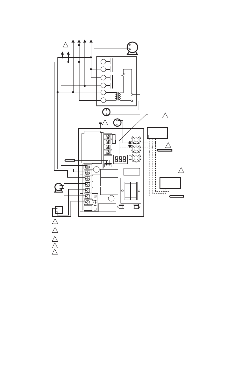
RÉGULATEURS À MAZOUT AQUASTAT® L7224A,C; L7248A,C,L
L1
(CHAUD)
CIRCULATEUR
(TENSION SECTEUR)
TENSION SECTEUR,
RELAIS DU
BRÛLEUR
À MAZOUT
VERS LES RELAIS R845A ADDITIONNELS
POUR D’AUTRES ZONES
1
L2
CAPTEUR
ELL=OFF (ARRÊT)
R845A RELAIS ZONE 2
THERMOSTAT
BASSE TENSION
ZONE 2
L7248L
ZR
L1
L2
C2
B2
C1
B1
ZC
6
5
3
4
1
2
2
LINE
T
T3
2
1
CIRCULATEUR
ZONE 2
THERMOSTAT
BASSE TENSION
BORNES
4
ENVIRACOM
50022037-002 MODULE DE
RÉARMEMENT D’EXTÉRIEUR
1 2 3 OT OT
3
C7089U1006
CAPTEUR
D’EXTÉRIEUR
50022037-005
MODULE D’EAU
CHAUDE DOMESTIQUE
1 2 3 TS TS
32003971-003
CAPTEUR DE
TEMPÉRATURE
5
ALIMENTATION. FOURNIR AU BESOIN UN DISPOSITIF DE COUPURE ET UNE PROTECTION
1
CONTRE LES SURCHARGES.
2
LE BOÎTIER DE COMMANDE DOIT ÊTRE BRANCHÉ À LA MASSE DE TERRE. UTILISER LA
VIS DE MISE À LA TERRE FOURNIE.
3
CAPTEUR D’EXTÉRIEUR ET MODULE DE RÉARMEMENT D’EXTÉRIEUR (EN OPTION).
BORNES ENVIRACOM.
4
5
CAPTEUR D’EXTÉRIEUR ET MODULE D’EAU CHAUDE DOMESTIQUE (EN OPTION).
Fig. 11. L7228l système multizones avec connexions du circulateur.
68-0281EFS—06 16
MF29655
Page 33
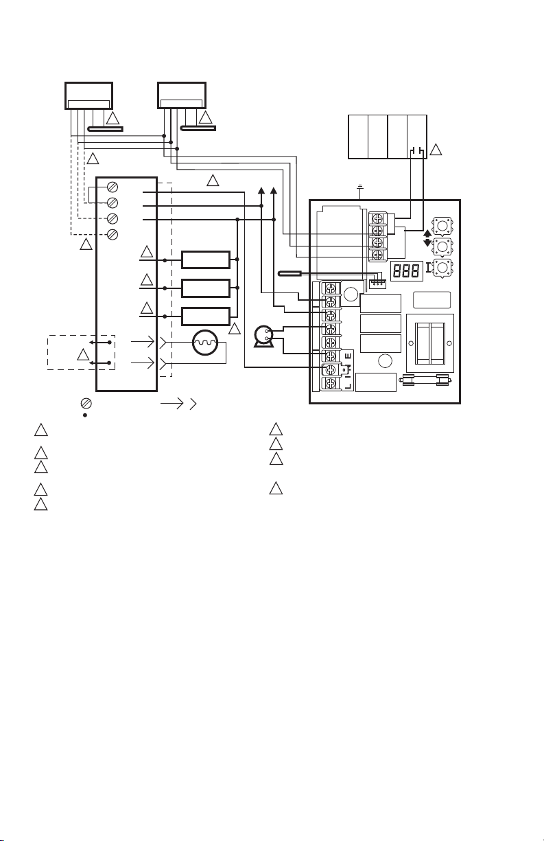
RÉGULATEURS À MAZOUT AQUASTAT® L7224A,C; L7248A,C,L
MF32024
ALIMENTATION. ASSURER AU BESOIN UN DISPOSITIF DE COUPURE ET
UNE PROTECTION CONTRE LES SURCHARGES.
FONCTION EN OPTION SUR DES MODÈLES SÉLECTIONNÉS.
SE REPORTER À L’ÉTIQUETTE DE L’APPAREIL POUR CONNAÎTRE LE
CODE DE COULEUR DE FIL.
LA VANNE EST OPTIONNELLE POUR LES MODÈLES SPÉCIFIÉS.
LA BORNE ENVIRACOM™ 3 EST ÉGALEMENT LA PREMIÈRE BORNE DU THERMOSTAT.
1
2
3
C1
B1
ZC
L2
LINE
C2
ZR
L1
B2
T
T
3
2
1
CAPTEUR
CIRCULATEUR
(TENSION
SECTEUR)
L7224
3
4
3
3
5
MOTEUR DE
BRÛLEUR
ALLUMEUR
VANNE
MOTEUR DE
BRÛLEUR
ALLUMEUR
VANNE
CELLULE
AU CADMIUM
BOÎTIER DE
RACCORDEMENT
VERS LE
CIRCUIT DE
L’ALARME
À DISTANCE
BORNE
ENVIRACOM™
R7184
LIMITE
L1
L2
2
CELLULE AU
CADMIUM
T
T
3
2
1
L1
(SOUS TENSION)
L2
1
LÉGENDE BORNE À VIS
BORNE DE CONNEXION
RAPIDE 6 MM (1/4 PO)
CONNEXION DE FIL SANS SOUDURE
CAPTEUR D’EXTÉRIEUR ET MODULE DE RÉARMEMENT D’EXTÉRIEUR EN OPTION.
MODULE D’EAU CHAUDE DOMESTIQUE EN OPTION.
CÂBLER UNIQUEMENT LES BORNES ENVIRACOM (1, 2, 3) SUR LE RÉGULATEUR À MAZOUT
PRIMAIRE EN CAS DE CONNEXION À UN SYSTÈME DE DIAGNOSTICS À DISTANCE, DANS
LE CAS CONTRAIRE CONNECTER À UN CAVALIER ENTRE LES BORNES TT.
LES BORNES DU TABLEAU DE ZONAGE PEUVENT AVOIR UNE ÉTIQUETTE DIFFÉRENTE.
VÉRIFIER LES CARACTÉRISTIQUES DU TABLEAU POUR LES INSTRUCTIONS DE CÂBLAGE.
6
7
8
1 2 3 TS TS
CAPTEUR DE
TEMPÉRATURE
32003971-003
7
MODULE D’EAU CHAUDE
DOMESTIQUE
50022037-005
9
TABLEAU DE RELAIS
MULTI-ZONES
T T
4
5
1 2 3 OT OT
CAPTEUR
D’EXTÉRIEUR
C7089U
6
MODULE DE RÉARMEMENT
D’EXTÉRIEUR
50022037-002
8
9
domestique (applications à réservoir indirect).
Fig. 12. Système multizones L7224/L7248 avec modules de réarmement d'extérieur et d'eau chaude
17 68-0281EFS—06
Page 34
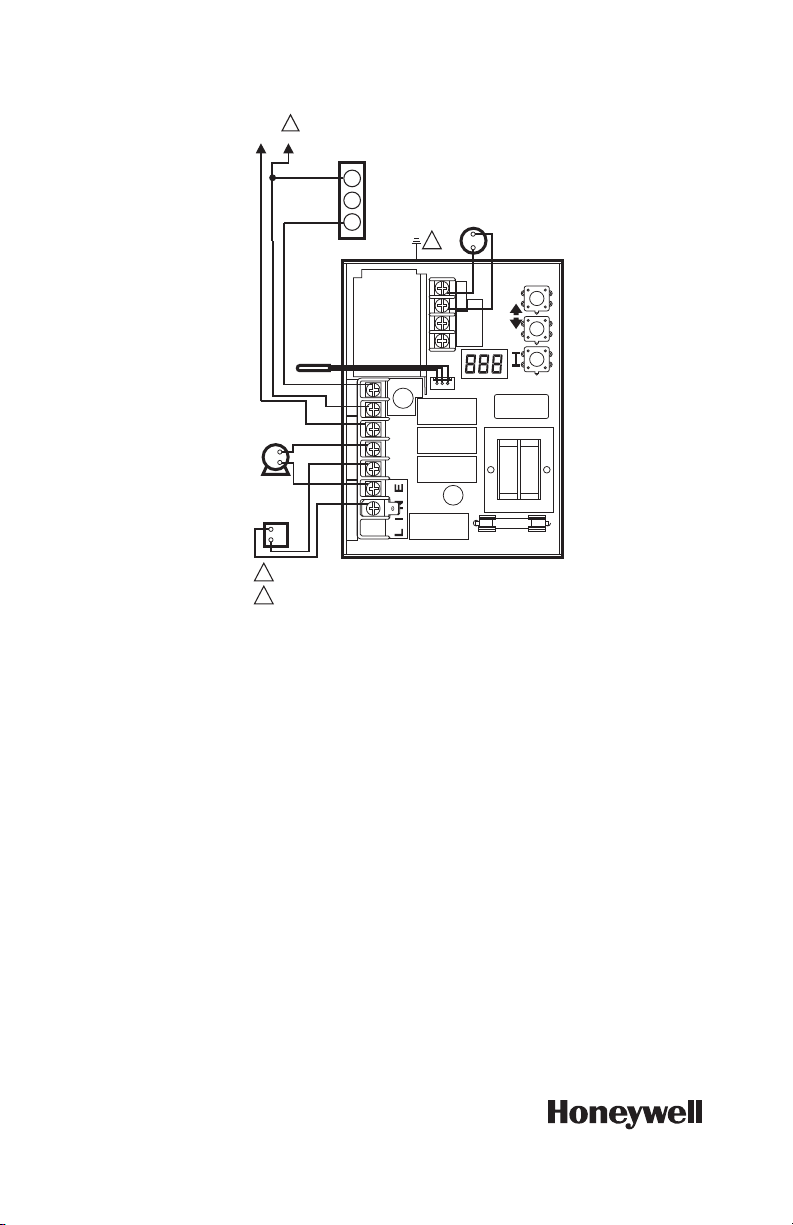
RÉGULATEURS À MAZOUT AQUASTAT® L7224A,C; L7248A,C,L
MF27113
1
2
W
L2
1
B
R
C1
B1
ZC
L2
LINE
C2
ZR
L1
B2
T
T3
2
1
2
L7248L
L1 (CHAUD)
CAPTEUR
CIRCULATEUR
(TENSION
SECTEUR)
TENSION
SECTEUR, RELAIS
DU BRÛLEUR
À MAZOUT
THERMOSTAT
BASSE
TENSION
ELL=ON (MARCHE)
L6006
RÉGULATEUR
LIMITE BASSE
ALIMENTATION. FOURNIR AU BESOIN UN DISPOSITIF DE COUPURE ET UNE
PROTECTION CONTRE LES SURCHARGES.
LE BOÎTIER DE COMMANDE DOIT ÊTRE BRANCHÉ À LA MASSE DE TERRE.
UTILISER LA VIS DE MISE À LA TERRE FOURNIE.
Fig. 13. L7248L Connexions limite basse externe.
Solutions de régulation et d’automatisation
Honeywell International Inc.
1985 Douglas Drive North
Golden Valley, MN 55422
customer.honeywell.com
® Marque de commerce déposée aux États-Unis
© 2012 Honeywell Inter national Inc.
Tous droits réservés
68-0281EFS—06 M.S. Rev. 09-12
Imprimé aux États-Unis
Page 35

Controladores electrónicos para
aceite L7224A,C; L7248A,C,L
Aquastat
®
APLICACIÓN
Los controladores electrónicos para aceite Aquastat®
L7224A,C y L7248A,C,L que cumplen con las
regulaciones 2012 proporcionan detección electrónica
de la temperatura en un controlador de límites
especificados por UL con una sola sonda detectora. Los
L7224A,C y L7248A,C,L controlan el circulador, el
quemador de aceite y la temperatura de la caldera. El
L7224/L7248 es apto para el "Reinicio de temperatura
exterior", que se habilita cuando está conectado al kit de
reinicio exterior W8735S1000. El reinicio exterior del
L7224/L7248 está destinado para todas las aplicaciones,
excepto para sistemas de serpentín sin tanque para
agua caliente doméstica. El cumplimiento con la
regulación 2012 del DOE (Departamento de Energía de
Estados Unidos) garantiza máxima eficacia sin interferir
con las exigencias de agua caliente doméstica.
Los modelos L7224A,C y L7248A,C,L reemplazan a los
controladores L8124A, L8124C, L7124A,C, L7148A y
L8148A. Los controles de la serie L7224A,C y
L7248A,C,L muestran el estatus y la información de
diagnóstico mediante un visualizador LED combinado
con luces LED, así como también con termostatos de
comunicación habilitados con EnviraCOM™ y
herramientas de diagnóstico, para mejorar el proceso de
diagnóstico.
Los controladores Aquastat L7224/L7248 están
destinados para uso en aplicaciones de tipo residencial.
IMPORTANTE
El uso del reinicio de temperatura exterior en
una aplicación de serpentín sin tanque, que
requiere una configuración de límite mínimo,
provocará una disminución en la efectividad y la
eficiencia del sistema.
INSTRUCCIONES DE INSTALACIÓN
ESPECIFICACIONES
Clasificación eléctrica:
Voltaje: 120 V CA, 60 Hz.
Alimentación eléctrica: máximo de 7 VA a 120 V CA más
cargas externas.
Corriente del termostato: 100 mA nominal a 24 V CA.
Relé del quemador:
7,4 A a 120 V CA a plena carga;
aflujo de corriente de 44,4 A, amperaje con rotor blo-
queado;
Carga menor de encendido: 360 VA.
Relé del circulador:
7,4 A a 120 V CA a plena carga; aflujo de corriente de
44,4 A, amperaje con rotor bloqueado.
Controlador de zonas (ZC): 7,4 A a 120 V CA a plena
carga;
aflujo de corriente de 44,4 A, amperaje con rotor blo-
queado.
NOTE: todas las cargas combinadas no pueden
exceder los 2000 VA.
Parámetros ambientales:
Temperatura: -30 °F a +150 °F (-34 °C a +66 °C).
Humedad: 0 a 95% de humedad relativa, sin conden-
sación.
Aprobaciones:
Reconocimiento de los componentes por parte de
Underwriters Laboratories Inc.
Reconocimiento de los componentes por parte de Cana-
dian Underwriters Laboratories Inc.
Cumplimiento y funcionamiento de acuerdo con el DOE 2012
El funcionamiento de este controlador puede retardar el funcionamiento del
quemador mientras el calor residual circula por fuera de la caldera.
NOTA:Este funcionamiento puede ser diferente de las revisiones electrónicas anteriores del
Aquastat®, las cuales no tenían la purga térmica implementada.
Page 36
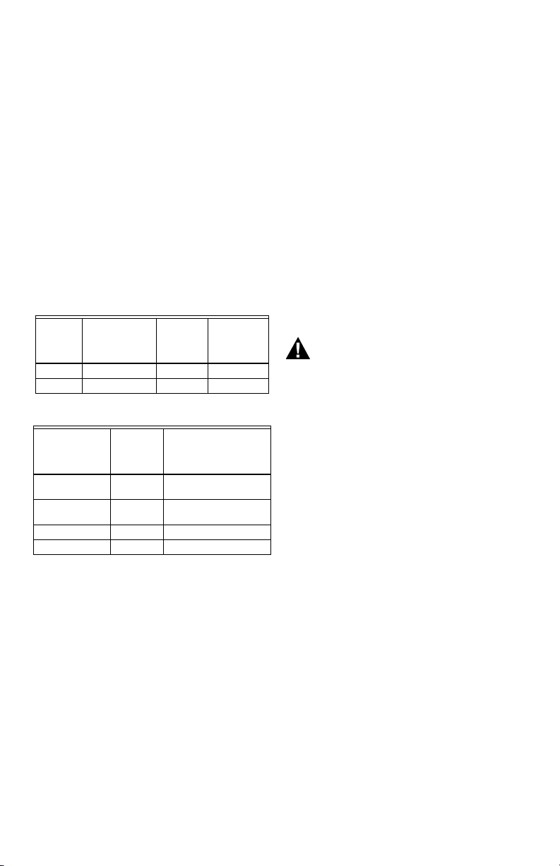
CONTROLADORES ELECTRÓNICOS PARA ACEITE L7224A,C; L7248A,C,L AQUASTAT®
ADVERTENCIA
Accesorios:
Kit inalámbrico de reinicio exterior W8735Y1000
Módulo de reinicio inalámbrico exterior W873ER1000
Sensor inalámbrico de temperatura exterior C7089R1013
(necesita W8735ER1000)
Kit de reinicio exterior AquaReset™ W8735S1000
(incluye el módulo de reinicio exterior 50022037-002 y
el sensor de temperatura exterior C7089U1006).
Kit para agua caliente doméstica AquaReset™
W8735S1008 (incluye el módulo para agua caliente
doméstica 50022037-005 y el sensor 32003971-003).
Módulo de alarma EnviraCOM™ W8735S3000
Sensor de temperatura exterior C7089U1006 (utilizado
con el 50022037-002).
Sensor de temperatura 32003971-003 (utilizado con el
50022037-005).
Sensor (consulte la Ta b l a 2 ).
Fusible para cartucho de vidrio 14000485-016 de 1/4 de
pulgada (6,35 mm) de diámetro y 1-1/4 pulgadas
(31,75 mm) de largo, 1 A, de acción retardada.
Compuesto conductivo de calor 120650.
Abrazadera del cilindro para sensor 121371AA.
Tabla 1. Cilindros para los controladores L7224A,C;
Número
de pieza
123869A 1/2 (12,7) NPT 3 (76,2) 1-1/2 (38,1)
123870A 3/4 (19,05) NPT 3 (76,2) 1-1/2 (38,1)
Tabla 2. Sensores para los controladores L7224A,C y
Número de
pieza
50001464-001 12 (304,8) Controles con montaje
50001464-003 24 (609,6) Controles con montaje a
50001464-004 36 (914,4)
50001464-005 48 (1219,2)
L7248A,C,L.
Tamaño de la
espita en
pulgadas (mm)
L7248A,C,L.
Longitud
en
pulgadas
(mm)
Inserción
en
pulgadas
(mm)
Aplicación
en cilindro
ras
Aislamiento
en pulgadas
(mm)
INSTALACIÓN
Cuando instale este producto...
1. Lea detenidamente estas instrucciones. De no
seguirlas, se podría dañar el producto o provocar
una situación peligrosa.
2. Verifique los valores nominales en el producto y en
las instrucciones, para asegurarse de que el
producto sea adecuado para la aplicación.
3. El instalador debe ser un técnico de servicio
capacitado y experimentado.
4. Después de terminar la instalación, verifique el
funcionamiento del producto tal como se indica en
estas instrucciones.
5. Ajuste el límite máximo, el límite mínimo y el
diferencial del límite mínimo según las
configuraciones recomendadas por el fabricante del
equipo original (OEM) de la caldera.
6. Registre la configuración máxima del límite máximo
del controlador reemplazado en el cuadro de texto
incluido en la etiqueta del inserto de la cubierta.
7. Registre la configuración del límite máximo al
momento de la instalación en el cuadro de texto
incluido en la etiqueta del inserto de la cubierta.
Peligro de descarga eléctrica.
Puede causar lesiones graves, muerte o daño
a la propiedad.
Desconecte el suministro eléctrico antes de
comenzar la instalación para evitar descargas
eléctricas o daños al equipo.
Montaje
Los modelos L7224A,C y L7248A,C,L están disponibles
para montaje en cilindro, en posición horizontal o vertical
o montaje a ras en un área remota con respecto a las
versiones con cilindro. Las dimensiones para las
diferentes opciones de montaje se muestran en la
Observe que cada identificación tendrá solo una opción
de montaje.
Fig. 1.
68-0281EFS—06 2
Page 37
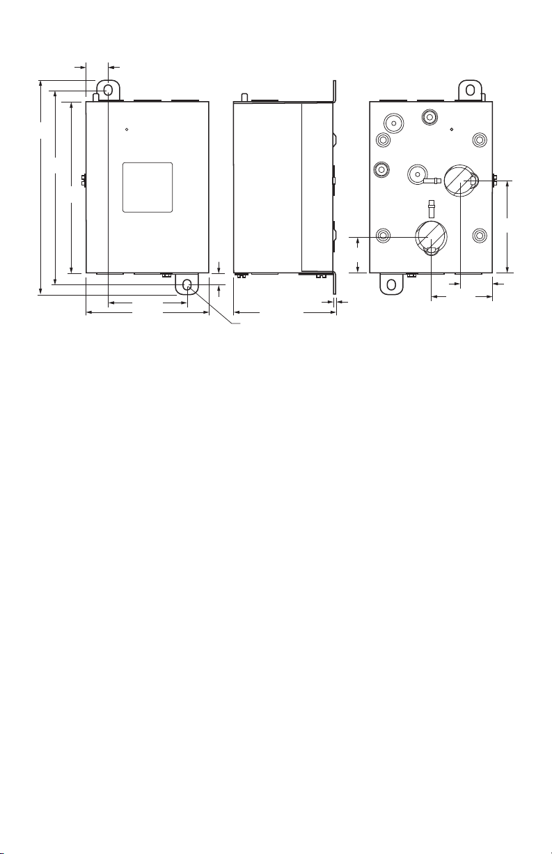
CONTROLADORES ELECTRÓNICOS PARA ACEITE L7224A,C; L7248A,C,L AQUASTAT®
M22147B
3/4
(75)
5-11/16
(145)
3/8
(10)
2-5/8 (67)
7-1/8
(181)
6-1/2
(166)
3-13/32 (86)
2x 1/4 (7) x 3/8 (9)
1/16 (2)
1-3/16
(30)
3-1/32
(77)
2-1/16 (53)
1-1/8 (29)
4-1/4 (109)
Fig. 1. Dimensiones del montaje de L7224A,C; L7248A,C,L en pulgadas (mm).
IMPORTANTE
El cilindro de inmersión debe encajar en el elemento sensor y el sensor debe quedar apoyado
contra la parte inferior del cilindro.
Instalación nueva
Pida los ensambles de cilindros por separado; consulte la
Tabl a 1 y el formulario N.º 68-0040, Cilindros de
inmersión y conectores de compresión para
controladores de temperatura. Las calderas
generalmente tienen perforaciones para que el cilindro
pueda montarse en posición horizontal, de modo que el
agua de la caldera que se encuentra a temperatura
promedio pueda circular libremente en el cilindro.
1. Desconecte la energía eléctrica y vacíe la caldera,
si corresponde.
2. Si no cuenta con una perforación, prepare una
perforación con rosca de tamaño adecuado cerca
de la parte superior de la caldera.
3. Cubra moderadamente las roscas del cilindro con
lubricante para tuberías.
NOTA: no intente ajustar utilizando la cubierta como
manija.
4. Coloque el cilindro en la perforación de la caldera y
ajústelo por completo.
5. Vuelva a llenar la caldera y verifique que no haya
ninguna filtración de agua.
6. Afloje, pero no quiete, el tornillo de la abrazadera
del cilindro.
7. Encaje la cubierta en el cilindro de manera que la
abrazadera de la cubierta se deslice sobre la brida
del cilindro.
8. Ajuste bien el tornillo de la abrazadera.
9. Introduzca el elemento sensor en el cilindro hasta
que toque fondo. Consulte la sección Instalación
del sensor de reemplazo para obtener detalles. (Si
es necesario, doble un poco el cable que se
encuentra dentro de la cubierta para mantener el
sensor contra la parte inferior del cilindro).
10. CONECTE la energía eléctrica.
11. Ajuste el límite máximo, el límite mínimo y el
diferencial del límite mínimo según las
configuraciones recomendadas por el OEM de la
caldera. (Vea la sección FUNCIONAMIENTO).
(Consulte los pasos 6 y 7 de la sección
INSTALACIÓN).
12. En los modelos L7248L, ajuste la opción ELL (límite
mínimo exterior) para que coincida con su
configuración (consulte la sección
FUNCIONAMIENTO y las
IMPORTANTE
Si utiliza un cilindro que encaje correctamente
en el sensor, obtendrá una mejor respuesta tér
mica. Introduzca el sensor hasta que quede
apoyado contra la parte inferior del cilindro. Uti
lice un cilindro de longitud adecuada y doble el
cable, si es necesario, para mantener el bulbo
contra la parte inferior del cilindro.
Si el cilindro no encaja bien en el sensor, utilice
el compuesto conductivo de calor (incluido en
los modelos TRADELINE®), tal como se indica a
continuación: pliegue la bolsa de plástico del
compuesto longitudinalmente y gírela
suavemente. Luego, corte el extremo de la bolsa
y utilice el extremo abierto de la bolsa para
colocarla a lo largo de todo el cilindro. Retire
lentamente la bolsa mientras la aprieta con
firmeza para distribuir el compuesto de manera
uniforme en el cilindro. Doble el cable, si es
necesario, para mantener el sensor contra la
parte inferior del cilindro y para mantener el
extremo externo del sensor en contacto firme
con la parte lateral del cilindro. Consulte la
2. Limpie el exceso de compuesto del extremo
externo del cilindro.
Fig. 11 y 13).
Fig.
-
-
3 68-0281EFS—06
Page 38
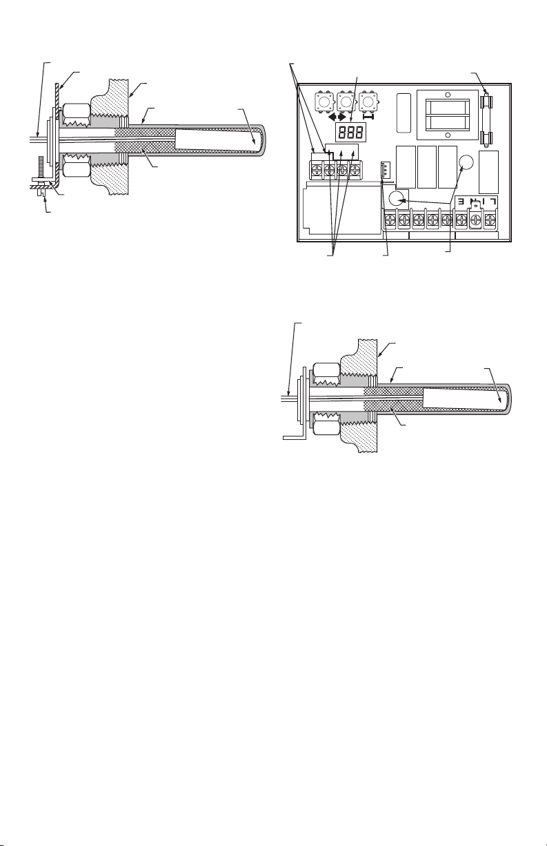
CONTROLADORES ELECTRÓNICOS PARA ACEITE L7224A,C; L7248A,C,L AQUASTAT®
CABLES DEL SENSOR
TORNILLO DE LA ABRAZADERA
DEL CILINDRO DE INMERSIÓN
ABRAZADERA
DEL CILINDRO DE INMERSIÓN
MS16120
COMPUESTO CONDUCTIVO
DE CALOR (OPCIONAL)
CUBIERTA DEL CONTROLADOR
CALDERA
CILINDRO
DE INMERSIÓN
SENSOR
TERMINALES DEL
Fig. 2. Posición del sensor en el cilindro de
inmersión.
Reemplazo del Aquastat montado a ras
Desconecte la energía eléctrica y retire el control viejo.
Consulte el inserto de la cubierta del control viejo para
identificar y marcar cada conductor externo a medida que
se desconecten. Si el cilindro viejo no es compatible con
la nueva instalación, retírelo y reemplácelo por un cilindro
nuevo compatible. Si el cilindro viejo es compatible,
utilícelo.
TERMOSTATO
TERMINALES
ENVIRACOM
Fig. 3. Circuito impreso con las conexiones del
sensor y los orificios del cilindro para los modelos de
PANTALLA
2
T
T3
CONECTOR
TM
DEL SENSOR
CABLES DEL SENSOR
1
montaje horizontal.
Reemplazo del Aquastat montado en cilindro
Desconecte la energía eléctrica y retire el control viejo.
Consulte el inserto de la cubierta del control viejo para
identificar y marcar cada conductor externo a medida que
se desconecten. Si el cilindro viejo no es compatible con
la nueva instalación, retírelo y proceda con las
instrucciones para la instalación nueva. Si el cilindro viejo
es compatible, utilícelo.
1. Afloje, pero no quite, el tornillo de la abrazadera del
cilindro que se encuentra en la parte lateral de la
cubierta del control.
2. Coloque la abrazadera del cilindro de inmersión
perfectamente sobre la brida del adaptador y ajuste
el tornillo de la abrazadera.
3. Introduzca el sensor en el cilindro, tal como se
muestra en las
Instalación del sensor de reemplazo para más detalles).
Fig. 2 y 3. (Consulte la sección
Fig. 4. Instalación del sensor de reemplazo.
Instalación del sensor de reemplazo
Desconecte la energía eléctrica y:
1. Con cuidado, desconecte el sensor del circuito
impreso halando suavemente del conector.
2. Hale suavemente el sensor desde el cilindro
térmico y a través del circuito impreso halándolo
por los cables conductores.
3. Con cuidado, alinee el sensor de reemplazo con el
orificio del circuito impreso y guíelo a través de la
cubierta Aquastat y dentro del cilindro. (Consulte la
Fig. 5).
4. Asegúrese de que el sensor esté completamente
asentado en la parte inferior del cilindro (consulte la
Fig. 4). Si es necesario, utilice un lápiz pequeño
para medir la profundidad del sensor en el cilindro.
5. Para conectar el sensor al circuito impreso,
presione el conector de la unidad del sensor sobre
el conector de acoplamiento del circuito impreso
(consulte la
6. Para sensores remotos (controladores Aquastat
montados a ras), asegúrese de utilizar la
abrazadera 121571AA (consulte la sección
Accesorios) para mantener el sensor firme en su
lugar.
Fig. 5).
FUSIBLE
LINE
L2
L1
ZR
C2
ORIFICIOS DEL
SENSOR
CALDERA
CILINDRO DE
INMERSIÓN
COMPUESTO CONDUCTIVO
DE CALOR (OPCIONAL)
B2
C1
SENSOR
B1
ZC
MS32186
MS22026
68-0281EFS—06 4
Page 39
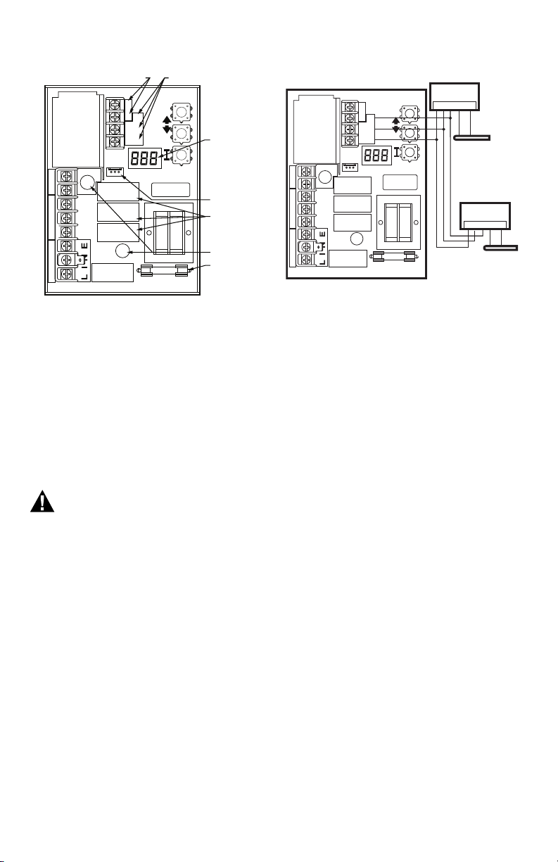
CONTROLADORES ELECTRÓNICOS PARA ACEITE L7224A,C; L7248A,C,L AQUASTAT®
ADVERTENCIA
C1
B1
ZC
L2
LINE
C2
ZR
L1
B2
T
T 3
2
1
TERMINALES
DEL TERMOSTATO
TERMINALES
ENVIRACOM
TM
PANTALLA
CONECTOR
DEL SENSOR
ORIFICIOS
DEL SENSOR
FUSIBLE
RELÉS
MS32187
C1
B1
ZC
L2
LINE
C2
ZR
L1
B2
T
T
3
2
1
1 2 3 OT OT
C7089U1006
SENSOR DE EXTERIORES
50022037-002
MÓDULO DE
REINICIO EXTERIOR
1 2 3 TS TS
50022037-005
MÓDULO PARA AGUA
CALIENTE DOMÉSTICA
32003971-003
SENSOR DE
TEMPERATURA
MS29651
Fig. 5. Circuito impreso con las conexiones del
sensor y los orificios del cilindro para los modelos de
montaje vertical.
Fig. 6. Cableado del módulo de reinicio exterior y del
módulo para agua caliente doméstica.
FUNCIONAMIENTO
Fusible
El fusible de 1 Amp ubicado cerca del transformador está
destinado a proteger el circuito EnviraCOM del cableado
incorrecto. El Aquastat continuará funcionando aunque el
fusible se dispare o se retire pero no será posible la
comunicación de EnviraCOM en el bus y aparecerá Err 6
en la pantalla. Consulte la
Tabl a 1 0.
CABLEADO
Peligro de descarga eléctrica.
Puede ocasionar lesiones graves o la muerte.
Desconecte el suministro eléctrico antes de
realizar las conexiones de cableado para evitar
descargas eléctricas o daños al equipo.
Todo el cableado debe cumplir con las ordenanzas y los
códigos eléctricos locales. No exceda las
especificaciones de la sección Aplicación cuando realice
el cableado de este control. Utilice cables calificados para
194 °F (90 °C) o más.
IMPORTANTE
Los terminales de estos controladores Aquastat
están aprobados para ser utilizados únicamente
con cables de cobre.
Siga los diagramas de cableado correspondientes que
figuran en el interior de la cubierta frontal de los modelos
L7224A,C; L7248A,C,L o en las
Consulte la Fig. 6 para ver las conexiones para el módulo
de reinicio exterior y el módulo para agua caliente
doméstica (DHW). En los diagramas de cableado
subsiguientes, estos módulos se mostrarán con una línea
de puntos para indicar que son opcionales.
Fig. 8-13.
General
Los controladores electrónicos de aceite L7224A,C y
L7248A,C,L Aquastat son dispositivos primarios de
seguridad con límite nominal diseñados para ser
utilizados con calderas a aceite con quemadores y
circuladores de voltaje de línea. Muchas calderas no
incluyen los compartimientos para el cableado o el control
como parte del diseño, pero tienen un cilindro de
inmersión reemplazable e integral que funciona como
accesorio de montaje para los controladores Aquastat. El
cableado hacia otros controles se realiza mediante un
conducto de metal flexible.
Para las calderas que incluyen un control montado de
forma remota (a ras), el cableado puede completarse con
un conducto o colocar detrás de la lámina de metal de la
caldera.
No se requiere un límite máximo electromecánico por
separado en un sistema que utilice este control a fin de
cumplir con los requisitos de Underwriters Laboratories
Inc. para ensambles de calderas a aceite, UL 726.
En los modelos L7224, el límite máximo, el límite mínimo,
el diferencial del límite mínimo y el tiempo del ciclo
anticorto pueden ajustarse a las configuraciones
recomendadas por el OEM de la caldera. En los modelos
L7248, el límite máximo y el tiempo del ciclo anticorto son
ajustables; consulte "Ajuste de las configuraciones".
El rango general del límite máximo es de 130 °F a 240 °F
(54 °C a 116 °C). Algunos dispositivos exclusivos pueden
tener diferentes rangos. Algunos modelos tienen rangos
limitados para el punto de referencia del límite máximo;
estos rangos limitados están indicados en la etiqueta del
dispositivo.
Algunos modelos también pueden ajustar el límite mínimo
y el diferencial del límite mínimo. El rango del límite
mínimo es de 110 °F a 220 °F (43 °C a 104 °C). Algunos
dispositivos exclusivos pueden tener diferentes rangos.
5 68-0281EFS—06
Page 40
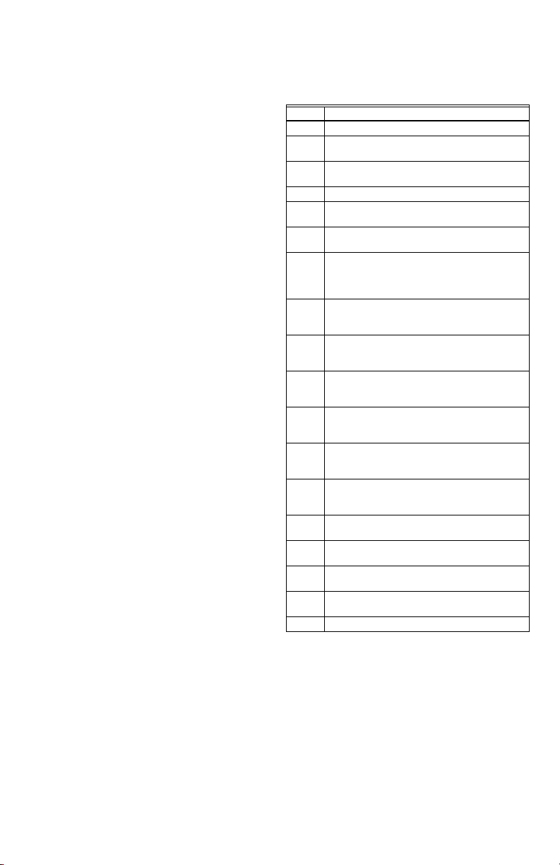
CONTROLADORES ELECTRÓNICOS PARA ACEITE L7224A,C; L7248A,C,L AQUASTAT®
La configuración Zr puede configurarse en agua caliente
doméstica (DHW), las zonas o en aplicaciones de
serpentín sin tanque dependiendo del L7224/L7248.
Si se instala un módulo de reinicio exterior W8735S1000
AquaReset™, la curva de reinicio puede configurarse
ingresando la temperatura exterior mínima, la
temperatura mínima (caldera) y la temperatura exterior
máxima en la pantalla de tres dígitos. El rango de la
temperatura exterior mínima es de -40 °F a 40 °F (-40 °C
a 4,4 °C) y tiene una configuración predeterminada de 0
°F (-18 °C). El rango de la temperatura exterior máxima
es de 30 °F a 70 °F (-1,1 °C a 21,1 °C) y tiene una
configuración predeterminada de 40 °F (4,4 °C). El rango
de la temperatura mínima (agua o caldera) es de 80 °F a
180 °F (26,7 °C a 82,2 °C) y tiene una configuración
predeterminada de 130 °F (54 °C). Consulte las
instrucciones para la instalación del "Módulo de reinicio
exterior" (formulario número 69-2335) para obtener más
información acerca de la configuración de la curva de
reinicio de la caldera y de todos los parámetros
relacionados.
Los modelos L7224A,C y L7248A,C,L están diseñados
para utilizarse con termostatos electromecánicos y
electrónicos de 24 V CA o con termostatos habilitados
con EnviraCOM™, y tienen terminales tipo tornillo para
una fácil conexión en campo.
Ajuste de las configuraciones
Para evitar cambios no autorizados de las
configuraciones del Aquastat, es necesario realizar un
procedimiento para ingresar al modo ADJUSTMENT
(ajuste). Para ingresar al modo ADJUSTMENT (ajuste),
presione simultáneamente los botones UP (arriba),
DOWN (abajo) e I (consulte la
segundos. Presione el botón I hasta que se muestre la
función que necesita ajustar:
Tabla 3. Características regulables.
Display Definition
HL_ High Limit (Límite máximo).
FP_ Protección contra escarcha (Encendido/
apagado) (solo en L7248L)
Hdf High Limit Differential (Diferencial del límite
máximo).
LL_ Low Limit. (Límite mínimo). (L7224A, C)
Ldf Low Limit Differential (Diferencial del límite
mínimo). (L7224A, C)
ELL External Low Limit (Límite mínimo exterior).
(L7248L only)
duu Entrada de petición de zona (ZR) configurada
como petición de agua caliente doméstica
(DHW) (ON [encendido]/OFF[apagado]).
(L7224A,C/L7248L)
ASC Anti Short-Cycle Timeout (Interrupción del ciclo
anticorto); (segundos); "OFF" (apagado) está
desactivado.
otL* Outdoor Temperature Low (Parámetro de
temperatura exterior baja [mínima] para la
curva de reinicio exterior). (°F or °C).
otH* Outdoor Temperature High (Parámetro de
temperatura exterior alta [máxima] para la curva
de reinicio exterior). (°F or °C).
btL* Boiler Temperature Low (Parámetro de
temperatura baja [mínima] de la caldera para la
curva de reinicio exterior).
bP* Boost Period (Período de refuerzo) (minutos).
"OFF" (apagado) se muestra si el refuerzo está
inactivo.
bS* Boost step (Fase de refuerzo [°F o °C] que se
muestra únicamente si el refuerzo está activo).
(bP=ON (encendido)
UUS* Temperatura de apagado en climas cálidos (°F
o °C).
tPL** Temperatura límite de purga térmica (°F o °C),
“OFF” (apagado) si está deshabilitado
tPt** Retardo de tiempo para purga térmica
(minutos), mostrado solo si tPL está habilitado
PC Ciclo de encendido/apagado (ON/OFF) de la
bomba
F-C Unidades de temperatura (°F o °C).
* Configuraciones disponibles para el ajuste en la pantalla
de tres dígitos únicamente si se instala el módulo de
reinicio exterior W8735S1000 AquaReset.
**Configuraciones disponibles para ajuste solo cuando el
kit de reinicio de exteriores AquaReset W8735S1000
NO está instalado.
Luego, presione los botones UP (arriba) o DOWN (abajo)
para mover el punto de referencia hasta el valor deseado,
para cambiar entre °F y °C o para activar (on) o
desactivar (off) el límite mínimo exterior. Después de 60
segundos sin presionar botones, el control regresará
automáticamente al modo RUN (ejecutar).
Fig. 5) durante tres
68-0281EFS—06 6
Page 41

CONTROLADORES ELECTRÓNICOS PARA ACEITE L7224A,C; L7248A,C,L AQUASTAT®
Pantalla
En el modo RUN (ejecutar), el Aquastat mostrará "bt"
(temperatura de la caldera) seguido por la temperatura
(es decir, 220), seguido por °F o °C.
Para ver las configuraciones de la caldera, presione I para
ver el parámetro que le interese. Por ejemplo, presione I y
aparecerá el límite máximo (HL), seguido por un número
de tres dígitos, es decir, 220, seguido por °F o °C. Si
presiona nuevamente el botón I (en los modelos L7224),
aparecerá el límite mínimo (LL) seguido por un número
de tres dígitos y el correspondiente denominador de
grados. Consulte la lectura de la pantalla,
Después de, aproximadamente, 60 segundos sin
presionar ninguna tecla, la pantalla entrará en el modo de
pantalla tenue. Para regresar al modo de pantalla
luminosa, simplemente presione cualquier tecla.
Tabl a 4 .
Tabla 4. Definiciones de la lectura de la pantalla.
La
2
pantalla
muestra
Texto Descripción
Err Código de error (si hubiera uno)
bT Temperatura de la caldera
HL
Límite máximo
HdF Diferencial del límite máximo
LL Límite mínimo (únicamente en el L7224)
Ldf Diferencial del límite mínimo
(únicamente en el L7224)
tt Estado del termostato local
ttE Estado del termostato EnviraCOM
brn Salida B1 (quemador)
(ON [encendido] u OFF [apagado])
Cir Salida C1 (circulador)
(ON [encendido] u OFF [apagado])
ZC Salida ZC (control de zonas)
(ON [encendido] u OFF [apagado])
Zr Orden de CALEFACCIÓN de ZR (peticiónde
zona) (ON [encendido] u OFF [apagado])
ELL Límite mínimo exterior habilitado
(únicamente en el L7248L)
duu Petición de zona (ZR) configurada como
petición de agua caliente doméstica
(únicamente en los modelos L7224, L7248L)
ASC Interrupción del ciclo anticorto
bSP
Punto de referencia de la caldera
dhc Módulo para agua caliente
domésticaconectado
ot
Temperatura exterior
otL
Temperatura exterior baja
otH
Temperatura exterior alta
btL
Temperatura baja de la caldera
bP
Período de refuerzo
bS
Fase de refuerzo
UUS
Temperatura de apagado en climas cálidos
1
La pantalla muestra la configuración local;no la configuración
modificada mediante uncontrol externo enviracom.
2
Las configuraciones son visibles únicamentesi el módulo de
reinicio exterior y el sensorde temperatura exterior están insta
lados y funcionan correctamente.
3
Las configuraciones son visibles únicamentesi el módulo para
agua caliente doméstica y el sensor están instalados y funcio
nan correctamente.
1
3
(YES [sí] o NO [no])
2
2
2
2
2
2
2
-
-
7 68-0281EFS—06
Page 42

CONTROLADORES ELECTRÓNICOS PARA ACEITE L7224A,C; L7248A,C,L AQUASTAT®
A
Funcionamiento
Los modelos L7224 y L7248 pueden encontrarse en
cualquiera de los cuatro estados de funcionamiento:
normal, límite máximo, límite mínimo y error. El
controlador va y viene entre el estado de límite máximo y
el estado normal y de límite mínimo, como parte del
funcionamiento normal. Únicamente los dispositivos que
tienen configuraciones de límite máximo están
restringidos para el estado normal y de límite máximo. Sin
embargo, el controlador ingresará en estado de error si se
presenta una condición anormal. Los estados de
funcionamiento son:
1. Normal: la temperatura de la caldera descendió por
debajo de la configuración de límite máximo
(menos el diferencial) y no superó la configuración
de límite máximo; o bien, la temperatura de la
caldera superó la configuración de límite mínimo y
no descendió por debajo de la configuración de
límite mínimo (menos el diferencial); o bien, la
entrada de petición de zona (ZR) no está siendo
alimentada con 120 V CA (únicamente en el
L7248L con ELL [límite mínimo exterior]
configurado en encendido).
2. High Limit (Límite máximo): la temperatura de la
caldera superó la configuración de límite máximo y
no descendió por debajo de la configuración de
límite máximo (menos el diferencial).
3. Low Limit (Límite mínimo): la temperatura de la
caldera descendió por debajo de la configuración
de límite mínimo (menos el diferencial del límite
mínimo) y no superó la configuración de límite
mínimo; o bien, la entrada de petición de zona (ZR)
está siendo alimentada con 120 V CA (únicamente
en el L7248L con ELL [límite mínimo exterior]
configurado en encendido).
4. Error: el controlador detectó una condición de error
(por ejemplo, un sensor abierto) y cerró la salida del
quemador. La salida del control de zonas (ZC) se
activa. El controlador continúa monitoreando el
sistema y automáticamente se reinicia si la
condición de error desaparece.
Consulte la Tab la 7. La secuencia de funcionamiento para
los modelos L7224/L7248 se muestra en la Tabl a 6 -9.
Controlador de límite máximo
El límite máximo enciende y apaga el quemador cuando
la temperatura del agua alcanza el punto de referencia. El
límite máximo se reinicia automáticamente después de
que la temperatura del agua desciende por debajo del
punto de referencia y por el diferencial. Los modelos
L7248 tienen el diferencial del límite máximo
predeterminado en 15 °F (8 °C). Los modelos L7224
tienen el diferencial del límite máximo predeterminado en
10 °F (6 °C).
Controlador de límite mínimo y circulador
Al registrarse un ascenso de temperatura, con el
diferencial ajustable en la configuración predeterminada
de 10 °F (6 °C), el circuito del quemador se desconecta y
el circuito del circulador se conecta (suponiendo que no
exista una orden de calefacción) en el punto de referencia
de límite mínimo. Al registrarse un descenso de
temperatura de 10 °F (6 °C) por debajo del punto de
referencia del límite mínimo, el circuito del quemador se
conecta y el circuito del circulador se desconecta.
Consulte la
Fig. 7.
EL INTERRUPTOR SE
DESCONECTA AL AUMENTAR LA
TEMPERATURA. EL QUEMADOR
CONFIGURACIÓN
DEL LÍMITE
MÁXIMO
CONFIGURACIÓN
DEL LÍMITE
MÍNIMO
1
L7224: DIFERENCIA DE
10 °F (6 °C)
L7248: DIFERENCIA DE
15 °F (8 °C)
DIFERENCIA DE
10 ºF (6 ºC)
CUANDO EL AGUA ALCANZA LA CONFIGURACIÓN DE LÍMITE MÍNIMO,
EL QUEMADOR SE APAGA O LA BOMBA DEL CIRCULADOR SE ENCIENDE
(CUANDO SE EMITE UNA ORDEN DE CALEFACCIÓN).
SE APAGA. EL CIRCULADOR
FUNCIONA CUANDO SE EMITE
UNA ORDEN DE CALEFACCIÓN.
EL INTERRUPTOR SE CONECTA
AL BAJAR LA TEMPERATURA.
EL QUEMADOR FUNCIONA
CUANDO SE EMITE UNA ORDEN
DE CALEFACCIÓN.
SIN UNA ORDEN DE CALEFACCIÓN,
EL INTERRUPTOR SE DESCONECT
AL AUMENTAR LA
TEMPERATURA.
EL INTERRUPTOR SE CONECTA
AL BAJAR LA TEMPERATURA, EL
QUEMADOR SE ENCIENDE PARA
MANTENER LA TEMPERATURA
MÍNIMA DEL AGUA.
EL CIRCULADOR ESTÁ APAGADO.
1
MS23364
Fig. 7. Puntos de referencia y diferenciales.
Función de ciclo anticorto
La función de ciclo anticorto permite la selección en
campo de un tiempo de retardo entre los ciclos del
quemador. Si se emite una orden de calefacción al
finalizar el ciclo de calefacción anterior y antes de que se
acabe el tiempo de retardo del ciclo anticorto, el
circulador podrá comenzar a funcionar, pero el quemador
no se encenderá hasta que haya transcurrido el tiempo.
El rango de tiempo del ciclo anticorto es de APAGADO a
cinco minutos.
NOTA: esta función se bloquea si se emite una orden
de agua caliente doméstica. Las órdenes de
agua caliente doméstica se brindan de
inmediato, sin retardos.
NOTA: cuando el Aquastat está conectado al control
primario de aceite o al termostato mediante el
bus EnviraCOM, el tiempo del ciclo anticorto no
se aplica para reciclar situaciones tales como la
pérdida de la llama o del flujo de aire. Solo se
aplica cuando no hay una orden.
ZR: petición de agua caliente doméstica (DHW)
El terminal ZR puede estar configurado para brindar una
petición de calefacción mediante un calentador indirecto
de agua. Este parámetro se configura a través de la
pantalla de tres dígitos (consulte la sección Ajuste de las
configuraciones en este documento). Una petición de
calefacción a través del terminal ZR tendrá prioridad
sobre todas las demás funciones, tales como la función
de ciclo anticorto o aquellas funciones habilitadas
mediante el módulo de reinicio exterior (consulte el
formulario N.º 69-2335EFS para obtener más
información).
Protección contra el congelamiento
La función de protección contra el congelamiento protege
la caldera y potencialmente la plomería de la caldera
contra posibles daños que pudiesen ocurrir si el agua que
se encuentra en el sistema comienza a congelarse. La
función de protección contra el congelamiento está
habilitada solo en el L7248 (modelos de arranque en frío).
68-0281EFS—06 8
Page 43

CONTROLADORES ELECTRÓNICOS PARA ACEITE L7224A,C; L7248A,C,L AQUASTAT®
La configuración predeterminada de la función está
habilitada (ON), pero puede deshabilitarse utilizando la
pantalla de 3 dígitos. Consulte “Ajuste de las
configuraciones” en la
Cuando la temperatura de la caldera desciende a la
temperatura límite de protección contra el congelamiento
(establecida en 40
encendido. Las salidas del circulador y ZC permanecen
en el mismo estado en que estaban antes de que se
habilitara la función de protección contra el
congelamiento. Pueden estar en ON (encendidas) u OFF
(apagadas) durante el ciclo de protección contra el
congelamiento.
Cuando la temperatura de la caldera alcance el límite de
protección contra el congelamiento más un diferencial fijo
°F, el quemador se apaga a menos que deba
de 10
permanecer encendido debido a una demanda diferente.
página 6.
°F [4.4 °C]) el quemador fuerza el
Funcionamiento de la purga térmica
La intención de la purga térmica es garantizar que el calor
residual utilizable en la caldera circule hasta que se agote
lo suficiente en el sistema antes de que se encienda el
quemador. A tal fin, en una demanda de calefacción, el
quemador no se encenderá mientras el circulador
funcione hasta que la temperatura de la caldera baje a la
temperatura de purga térmica o se supere el retardo de la
Tabla 5. Configuraciones de purga térmica.
Nombre del parámetro Valor mínimo Valor máximo
Caída de la temperatura de la caldera No ajustable No ajustable 10 °F
Límite de temperatura de la purga térmica 120 °F (o OFF
Índice de descenso de temperatura de la purga
térmica
Retardo de la purga térmica 1 minuto 10 minutos 2 minutos
purga térmica. Estos dos parámetros son ajustables.
Cuando la temperatura de la caldera alcance la
temperatura de purga térmica, el quemador se enciende.
La purga térmica solo se aplica a los modelos Aquastat
de arranque en frío (L7248) y no interfiere con la
demanda de calor del agua caliente doméstica o las
calderas equipadas con los accesorios Honeywell de
reinicio en exteriores. Para los modelos de arranque en
caliente donde deberá configurarse un límite mínimo, no
se aplica la purga térmica.
Además de la temperatura de purga térmica y los
parámetros de retardo de la purga térmica, otras dos
condiciones evitan que el Aquastat haga la purga térmica
para mantener el confort en el espacio:
• La temperatura de la caldera ha bajado 10 °F desde el
comienzo de la purga térmica.
• La temperatura se está enfriando a un índice mayor de
°F/minuto mientras el circulador está funcionando.
5
La función de purga térmica se aplica a una sola zona así
como a las aplicaciones de zonas múltiples.
Configuraciones de purga térmica
Algunos parámetros de purga térmica son configurables
mediante la pantalla de tres dígitos. Consulte “Ajuste de
las configuraciones” en la
puede deshabilitarse configurando el límite de
temperatura de la purga térmica en "OFF" (apagado).
[apagado])
No ajustable No ajustable 5 °F/minuto
página 6. La purga térmica
Val or
predeterminado
160 °F 140 °F (L7248)
Purga térmica y agua caliente doméstica
La función de purga térmica se deshabilita
automáticamente cuando se presenta una demanda de
agua caliente doméstica desde el terminal Zr para
garantizar que el agua caliente esté disponible de manera
oportuna. Consulte "ZR: petición de agua caliente
doméstica (DHW)" en la
página 8.
Ciclos de encendido/apagado de la bomba
La función de encendido/apagado de la bomba ejercita la
bomba del sistema durante 15 segundos después de un
período no ajustable de cinco días en los cuales no hubo
actividad en la caldera. La configuración predefinida de la
función de encendido/apagado (ON) de la bomba se
habilita pero puede deshabilitarse (OFF) utilizando la
pantalla de tres dígitos. Consulte “Ajuste de las
configuraciones” en la
página 6.
VERIFICACIÓN
Haga funcionar el sistema y observe, al menos, un ciclo
completo para asegurarse de que el controlador esté
funcionando bien. Consulte la sección LOCALIZACIÓN Y
SOLUCIÓN DE PROBLEMAS para utilizar el LED que le
ayudará a identificar el funcionamiento del sistema.
LOCALIZACIÓN Y SOLUCIÓN DE PROBLEMAS
Cuando intente diagnosticar el funcionamiento del
sistema, consulte el visualizador LED que le ayudará a
identificar las áreas específicas que no están funcionando
correctamente. El visualizador LED mostrará Err, seguido
de un dígito (1-8). Consulte las
una descripción de cada error y las acciones sugeridas.
9 68-0281EFS—06
Tabl a 1 0 y 11 para obtener
Page 44

CONTROLADORES ELECTRÓNICOS PARA ACEITE L7224A,C; L7248A,C,L AQUASTAT®
AQUASTAT DEL TANQUE INDIRECTO
LINE
DE VOLTAJE DE LÍNEA
L2
T
T3
2
1
CIRCULADOR
DEL TANQUE
INDIRECTO
MS32023
2
MÓDULO DE
REINICIO EXTERIOR
50022037-002
1 2 3 OT OT
SENSOR DE
EXTERIORES
C7089U
SENSOR
CIRCULADOR
DE VOLTAJE
DE LÍNEA
RELÉ DEL
QUEMADOR
DE ACEITE
DE VOLTAJE
DE LÍNEA
1
2
Fig. 8. L7224A,C; L7248L de una sola zona de calor con tanque de agua indirecto y circuladores. Módulo de
L1
(CON CORRIENTE)
L1
(CON
CORRIENTE)
1
EL MÓDULO DE REINICIO EXTERIOR ES OPCIONAL.
PARA MEJOR DESEMPEÑO CONFIGURE DUU= ON (ENCENDIDO).
L2
ZR
L1
L2
C2
B2
C1
B1
ZC
reinicio exterior opcional.
Tabla 6. Secuencia de funcionamiento de los controladores L7224/L7248.
Acción Respuesta del sistema
Órdenes de calefacción del
termostato.
La temperatura de la caldera
supera el límite máximo.
El circulador arranca cuando la temperatura del agua es superior a la configuración del
límite inferior (si fuese pertinente) o superior al límite de temperatura de purga térmica
(tPL) si la función de purga térmica está habilitada. Se verifica la temperatura de la
caldera. El quemador se enciende cuando la temperatura del agua es inferior a la
configuración del límite máximo menos el diferencial o está en el límite de la
temperatura de purga térmica (tPL) o por debajo de él en calderas de arranque en frío si
el límite de temperatura de purga térmica está habilitado. Si el tPL está habilitado, el
quemador puede también encenderse si la temperatura de la caldera está
descendiendo a razón de 10 °F o más por minuto o si el retardo de purga térmica (tPt)
terminó.
Si se habilita el tiempo de ciclo anticorto, el quemador no se encenderá hasta que
transcurra el tiempo del ciclo anticorto configurado entre los ciclos, luego de que se
haya cumplido la orden de calefacción anterior.
El quemador se apaga. El quemador se enciende nuevamente cuando la temperatura
del agua desciende por debajo de la configuración de límite máximo menos el
diferencial. Si la purga térmica está habilitada, el quemador se enciende bien cuando se
alcance el límite de temperatura de la purga térmica, el retardo de la purga térmica haya
terminado o el índice de enfriamiento de la temperatura de la caldera exceda de 10 °F/
minuto.
El termostato está a gusto. El circulador y el quemador se apagan.
La temperatura de la caldera
desciende por debajo de la
configuración de límite
mínimo menos el diferencial
(si corresponde).
Condiciones de error 1-5. Si se detecta una condición de error, todas las salidas, excepto el ZC, se cierran. El
El quemador se enciende y el circulador se apaga. El quemador se detiene cuando la
temperatura del agua supera la configuración de límite mínimo. El quemador se enciende
cuando la temperatura del agua es inferior a la configuración de límite máximo menos el
diferencial.
quemador está apagado. El controlador continúa funcionando y se enciende nuevamente
cuando el error se soluciona. Durante la secuencia de verificación del error, el sistema
controla si hay variaciones en el sensor o corrosión en las conexiones.
Condición de error 6. La comunicación EnviraCOM no está disponible.
68-0281EFS—06 10
Page 45

CONTROLADORES ELECTRÓNICOS PARA ACEITE L7224A,C; L7248A,C,L AQUASTAT®
Tabla 6. Secuencia de funcionamiento de los controladores L7224/L7248.
Acción Respuesta del sistema
Condición de error 7. El controlador reinició la configuración de límite máximo, límite mínimo y diferencial en
Condición de error 8. Si se detecta la condición de error, todas las salidas, excepto el ZC, se cierran. El
una configuración predeterminada y continuará funcionando con esas configuraciones. El
rendimiento del sistema disminuirá.
quemador está apagado. El controlador continúa funcionando y se encenderá
nuevamente cuando las tres teclas del usuario se presionen simultáneamente durante
más de 60 segundos.
Condición de error 9*. El sistema continúa funcionando sin la función de reinicio exterior.
Condición de error 10*. El sistema continúa funcionando con los parámetros de reinicio exterior habilitados en la
Condición de error 11*. El sistema continúa funcionando con la temperatura de la caldera configurada en el límite
programación.
El error desaparece automáticamente.
máximo.
* La condición de error está disponible únicamente si se instala el módulo de reinicio exterior.
Tabla 7. Secuencia de funcionamiento de los controladores L7224/L7248 con múltiples zonas conectadas
mediante el terminal ZR.
Acción Respuesta del sistema
El terminal de petición de zona (ZR) está
conectado a L1 (la zona emite una orden de
calefacción).
La temperatura de la caldera supera el límite
máximo.
La entrada de petición de zona se desactiva
(las zonas están a gusto).
La temperatura de la caldera desciende por
debajo de la configuración de límite mínimo
menos el diferencial (si corresponde).
Se verifica la temperatura de la caldera. El quemador se enciende
cuando la temperatura del agua es inferior a la configuración del
límite máximo o está en el límite de la temperatura de purga térmica o
por debajo de él (tPL) en calderas de arranque en frío si el límite de
temperatura de purga térmica está habilitado. Si el tPL está
habilitado, el quemador puede también encenderse si la temperatura
de la caldera está descendiendo a razón de 10 °F o más por minuto o
si el retardo de purga térmica (tPt) terminó. Se aplica el tiempo del
ciclo anticorto, consulte la
El quemador se apaga. El quemador se enciende nuevamente
cuando la temperatura del agua desciende por debajo de la
configuración de límite máximo menos el diferencial. Si la purga
térmica está habilitada, el quemador se enciende bien cuando se
alcance el límite de temperatura de la purga térmica, el retardo de la
purga térmica ha terminado o el índice de enfriamiento de la
temperatura de la caldera excede de 10 °F/minuto.
Tabl a 6 .
El quemador se apaga.
El quemador se enciende y el control de zonas se desactiva. El
quemador se apaga y el control de zonas se vuelve a activar cuando
la temperatura del agua supera la configuración de límite mínimo.
.
Tabla 8. Secuencia de funcionamiento del controlador con dispositivo de límite mínimo exterior conectado
mediante el terminal ZR.
Acción Respuesta del sistema
El terminal de petición de zona (ZR) está
conectado a L1 (el límite mínimo exterior
emite una orden de calefacción).
La temperatura de la caldera supera el límite
máximo.
La entrada de petición de zona se desactiva
(el límite mínimo exterior está a gusto).
Se verifica la temperatura de la caldera. El quemador se enciende
cuando la temperatura del agua es inferior a la configuración de límite
máximo. El circulador se apaga.
El quemador se apaga. El quemador se enciende nuevamente
cuando la temperatura del agua desciende por debajo de la
configuración de límite máximo menos el diferencial.
El quemador se apaga.
11 68-0281EFS—06
Page 46

CONTROLADORES ELECTRÓNICOS PARA ACEITE L7224A,C; L7248A,C,L AQUASTAT®
Tabla 9. Secuencia de funcionamiento del controlador L7224 con agua caliente doméstica conectada
mediante el terminal ZR.
Acción Respuesta del sistema
El terminal de petición de zona (ZR) está
conectado a L1 (el agua caliente doméstica
emite una orden de calefacción).
La temperatura de la caldera supera el límite
máximo.
La entrada de petición de zona se desactiva
(el agua caliente doméstica está a gusto).
Se verifica la temperatura de la caldera. El quemador se enciende
cuando la temperatura del agua es inferior a la configuración de límite
máximo.
El quemador se apaga. El quemador se enciende nuevamente
cuando la temperatura del agua desciende por debajo de la
configuración de límite máximo menos el diferencial.
El quemador se apaga.
Tabla 10. Códigos de error LED.
Código de
error del
Aquastat
Causa/acción
Alarma
EnviraCOM
Err1 El sensor Aquastat falló; verifique el sensor de agua. 18
Err2 ECOM falló; verifique el cableado del EnviraCOM™. 18
Err3 Hay demasiado ruido eléctrico o la frecuencia está fuera de alcance. El equipo falló;
reemplace el controlador.
18, 58
Err4 B1 falló; verifique el voltaje/cableado de B1. 64
Err5 Línea baja; verifique L1-L2, 110 V CA. 59
a
Err6
Advertencia: fusible; verifique los cables del ECOM, reemplace el fusible. 92
Err7 Advertencia: EEPROM, HL, LL, Hdf, Ldf; reinicie con los valores predeterminados. N/D
b
Err 8
Err9
Err 10
Err 11
a
Se emitirán advertencias para informar que el sistema no está funcionando de forma óptima, pero el Aquastat
continúa funcionando y mantiene la temperatura de la caldera. Si se utiliza un módulo de reinicio exterior, las
advertencias pueden indicar un error en la configuración de la curva de reinicio; una o más funciones no están
funcionando de forma óptima y el Aquastat regresa a las configuraciones predeterminadas o deja de hacer funcionar
los algoritmos de reinicio exterior. Las advertencias desaparecen cuando se resuelven el o los problemas.
b
Para borrar la condición Err 8, presione y mantenga presionadas simultáneamente las tres teclas del usuario durante
60 segundos. La condición Err 8 desaparece y la pantalla vuelve a su funcionamiento normal. La condición Err 8 está
diseñada para detectar relés soldados en el Aquastat; esto únicamente ocurre, en condiciones normales, cerca del
final de la vida útil del control. Si la condición Err 8 ocurre a comienzos de la vida útil de los controles, asegúrese de
controlar la retroalimentación de voltaje a B1, cuando B1 debe estar apagado, y verifique el consumo de corriente en
el terminal b para asegurarse de que el quemador de aceite no esté consumiendo corriente excesiva. La condición
Err 8 continuará repitiéndose si no se borra la falla de B1.
B1 falló nuevamente (hay voltaje en B1 cuando la salida está apagada); verifique el voltaje/
cableado de B1.
a
Advertencia: falla en el sistema de reinicio exterior; se perdió la comunicación con el módulo
de reinicio exterior, falla en el módulo de reinicio exterior, se detectaron múltiples sensores
de temperatura exterior en el bus, o bien, hay una falla en el sensor de temperatura exterior.
Verifique el cableado del EnviraCOM (1, 2, 3), verifique el cableado del sensor.
a
Advertencia: falla del refuerzo; el modo de refuerzo estuvo activo, al menos, una vez por
ciclo durante los últimos 60 ciclos consecutivos. Verifique las configuraciones de la curva de
reinicio exterior.
a
Falla en el sensor/módulo para DHW; se perdió la comunicación con el módulo para DHW,
falla en el módulo para DHW o falla en el sensor de temperatura. Verifique el cableado del
EnviraCOM (1, 2, 3), verifique el cableado del sensor.
25
50, 53, 149
150
146, 147,
148
68-0281EFS—06 12
Page 47

Condición del
sistema
La caldera
está fría, la
casa está fría.
La caldera
está caliente,
la casa está
fría.
La caldera
está caliente,
no hay agua
potable
caliente.
CONTROLADORES ELECTRÓNICOS PARA ACEITE L7224A,C; L7248A,C,L AQUASTAT®
Tabla 11. Guía de localización y solución de problemas.
Condición de
diagnóstico
La pantalla está
APAGADA.
La pantalla está
ENCENDIDA.
Energía del sistema: 120 V CA. Conecte la energía del sistema.
T-T de 24 V CA No hay 24 V; reemplace el control.
24 V presentes; desconecte el
termostato, T-T corto.
120 V CA en B1-B2 • Si no es así, reemplace el control.
Verificación Acción
La caldera se enciende, verifique el cableado y
el termostato.
• Si es así, verifique el quemador y el
cableado.
Consulte el Err de la pantalla. —
La pantalla está
ENCENDIDA.
La pantalla está
ENCENDIDA.
120 V CA en C1-C2 • 120 V CA en C1-C2, verifique el cableado
La temperatura de la caldera es
inferior a la temperatura de límite
mínimo, espere a que la caldera
supere la temperatura de límite
mínimo.
¿La caldera supera el LL (límite
mínimo)? Si es así, verifique que
existan 120 V CA entre ZC y L2.
Configuración de límite mínimo
exterior (únicamente en el
L7248L)
¿La caldera supera el LL (límite
mínimo)? Si es así, verifique que
haya 120 V CA en ZR-L2
(únicamente en el L7248L con
ELL [límite mínimo exterior]
configurado en encendido).
Señal de demanda de la caldera
emitida por el calentador de agua
(bien 120 V CA en ZR-L2, o 0 V
CA en T-T; depende de la
instalación y la configuración
“duu”)
configuración "ddu" • Configure ddu en ON si la demanda del
Revise el módulo DHW y el
sensor DHW
hacia la bomba.
• El cableado está bien, ¿está funcionando la
bomba?
• Si no es así, reemplace la bomba.
• Si la bomba está funcionando, verifique que
no haya aire atrapado ni válvulas de zona
cerradas.
—
• Si no hay 120 V CA, reemplace el control.
• Si es así, verifique los relés de zonas, los
circuladores y el cableado.
• Configure el límite mínimo exterior (ELL) en
apagado para los sistemas de zonas
múltiples (consulte la
• Configure el ELL en encendido para el límite
mínimo exterior (consulte la
• Si no hay 120 V CA, verifique C1-C2
(consulte más arriba).
• Si es así, verifique el control de límite
mínimo exterior.
• 24 V CA en T-T (o 0 V CA en ZR-L2), revise
el cableado hacia el calentador de agua
• Si el cableado está bien, revise el calentador
de agua
calentador de agua de 120 V CA está
conectada a ZR
• Configure ddu en OFF si la demanda del
calentador de agua abierta/cerrada está
conectada a T-T
• El módulo DHW no está conectado
adecuadamente y/o el sensor DHW está
colocado inadecuadamente
Fig. 11).
Fig. 13).
13 68-0281EFS—06
Page 48
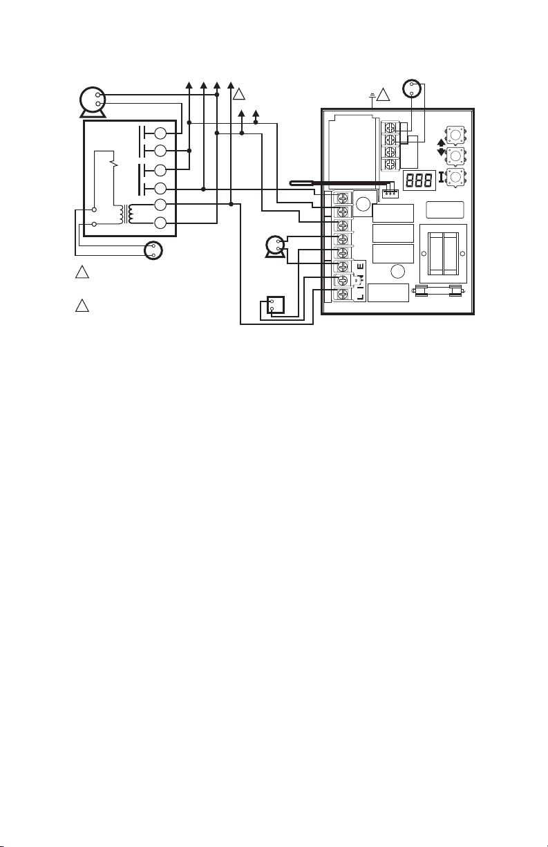
CONTROLADORES ELECTRÓNICOS PARA ACEITE L7224A,C; L7248A,C,L AQUASTAT®
É
A REL
CIRCULADOR
PARA ZONA 2
R845A RELÉ PARA ZONA 2
SUMINISTRO ELÉCTRICO. PROPORCIONE
1
LOS MEDIOS DE DESCONEXIÓN Y DE
PROTECCIÓN CONTRA SOBRECARGAS
SEGÚN SE REQUIERA.
LA CUBIERTA DEL CONTROL DEBE TENER
2
UNA CONEXIÓN A TIERRA. UTILICE EL
TORNILLO PARA CONEXIÓN A TIERRA INCLUIDO.
PARA OTRAS ZONAS
6
5
3
4
1
2
TERMOSTATO DE
BAJO VOLTAJE
PARA ZONA 2
S R845A ADICIONALES
1
L2
L1
(CON CORRIENTE)
SENSOR
CIRCULADOR
DE VOLTAJE
DE LÍNEA
RELÉ DEL
QUEMADOR DE
ACEITE DE
VOLTAJE DE
LÍNEA
ZR
L1
L2
C2
B2
C1
B1
ZC
L7224
2
T
T3
LINE
Fig. 9. Sistema de zonas múltiples del L7224A,C con conexiones para circuladores.
2
1
TERMOSTATO
DE BAJO
VOLTAJE
MS27115
68-0281EFS—06 14
Page 49
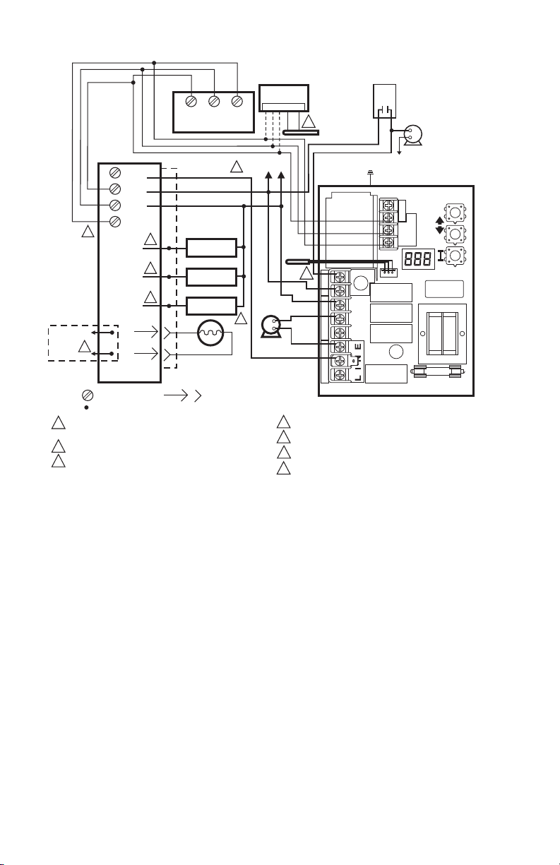
CONTROLADORES ELECTRÓNICOS PARA ACEITE L7224A,C; L7248A,C,L AQUASTAT®
MS32025
SUMINISTRO DE ENERGÍA. PROPORCIONE LOS MEDIOS DE DESCONEXIÓN
Y DE PROTECCIÓN CONTRA SOBRECARGAS SEGÚN SE REQUIERA.
FUNCIÓN OPCIONAL EN MODELOS SELECTOS.
CONSULTE LA ETIQUETA DEL DISPOSITIVO PARA VER EL CÓDIGO DE
COLOR DE LOS CABLES.
1
2
3
C1
B1
ZC
L2
LINE
C2
ZR
L1
B2
T
T
3
3
3
2
2
2
1
1
1
SENSOR
L7224
3
4
3
3
5
TH9421C
R7184
LIMIT
L1
L2
2
T
T
3
2
1
L2
1
LA VÁLVULA ES OPCIONAL EN MODELOS ESPECÍFICOS.
EL TERMINAL ENVIRACOM™ 3 TAMBIÉN ES EL PRIMER TERMINAL DEL TERMOSTATO.
MÓDULO DE REINICIO EXTERIOR Y SENSOR DE EXTERIORES OPCIONALES.
DUU DEBE ESTAR CONFIGURADO EN “ON” (ENCENDIDO) EN EL AQUASTAT.
4
5
6
1 2 3 OT OT
6
7
CIRCULADOR
DEL TANQUE
INDIRECTO
AQUASTAT DEL
TANQUE INDIRECTO
DE VOLTAJE DE LÍNEA
L2
7
CIRCULADOR
DE VOLTAJE
DE LÍNEA
MOTOR DEL
QUEMADOR
ENCENDEDOR
VÁLVULA
MOTOR DEL
QUEMADOR
ENCENDEDOR
VÁLVULA
CÉLULA
DE CADMIO
CAJA DE
EMPALMES
AL CIRCUITO
DE
ALARMA
REMOTA
TERMINAL
ENVIRACOM™
CÉLULA DE
CADMIO
L1 (CON
CORRIENTE)
LEYENDA TERMINAL DE TORNILLO
TERMINAL DE CONEXIÓN RÁPIDA
DE 1/4 DE PULGADA (6 MM)
CONEXIÓN DE CABLES SIN SOLDADURA
SENSOR DE
EXTERIORES
C7089U1006
MÓDULO DE
REINICIO EXTERIOR
50022037-002
EnviraCOM™.
15 68-0281EFS—06
Fig. 10. L7224A,C; L7248L con sistema de una zona con circulador y tanque de agua indirecto con termostato
Page 50
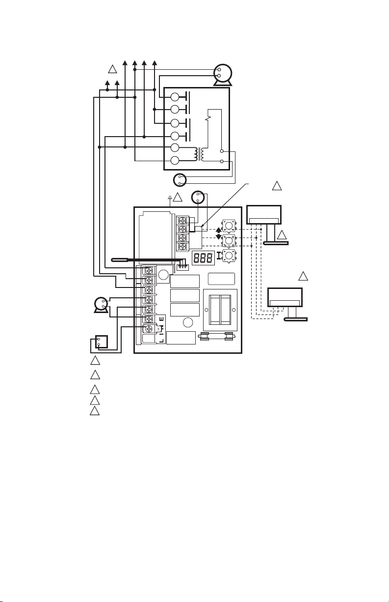
CONTROLADORES ELECTRÓNICOS PARA ACEITE L7224A,C; L7248A,C,L AQUASTAT®
L1
(CON
CORRIENTE)
CIRCULADOR
DE VOLTAJE
DE LÍNEA
RELÉ DEL
QUEMADOR
DE ACEITE DE
VOLTAJE DE LÍNEA
A RELÉS R845A ADICIONALES
PARA OTRAS ZONAS
1
L2
TERMOSTATO
VOLTAJE PARA ZONA 2
SENSOR
DE BAJO
L7248L
ZR
L1
L2
C2
B2
C1
B1
ZC
ELL=OFF (APAGADO)
CIRCULADOR
PARA ZONA 2
R845A RELÉ PARA ZONA 2
6
5
3
4
1
2
TERMOSTATO DE
2
LINE
BAJO VOLTAJE
T
T 3
2
1
TERMINALES
4
ENVIRACOM
50022037-002 MÓDULO DE
REINICIO EXTERIOR
1 2 3 OT OT
3
C7089U1006
SENSOR DE
EXTERIORES
50022037-005
MÓDULO PARA
AGUA CALIENTE
DOMÉSTICA
1 2 3 TS TS
5
32003971-003
SENSOR DE
TEMPERATURA
SUMINISTRO ELÉCTRICO. PROPORCIONE LOS MEDIOS DE DESCONEXIÓN Y DE
1
PROTECCIÓN CONTRA SOBRECARGAS SEGÚN SE REQUIERA.
2
LA CUBIERTA DEL CONTROL DEBE TENER UNA CONEXIÓN A TIERRA.
UTILICE EL TORNILLO PARA CONEXIÓN A TIERRA INCLUIDO.
3
MÓDULO DE REINICIO EXTERIOR Y SENSOR DE EXTERIORES OPCIONALES.
TERMINALES ENVIRACOM.
4
5
MÓDULO PARA AGUA CALIENTE DOMÉSTICA Y SENSOR DE TEMPERATURA OPCIONALES.
Fig. 11. Sistema de zonas múltiples del L7248L con conexiones para circuladores.
68-0281EFS—06 16
MS29655
Page 51
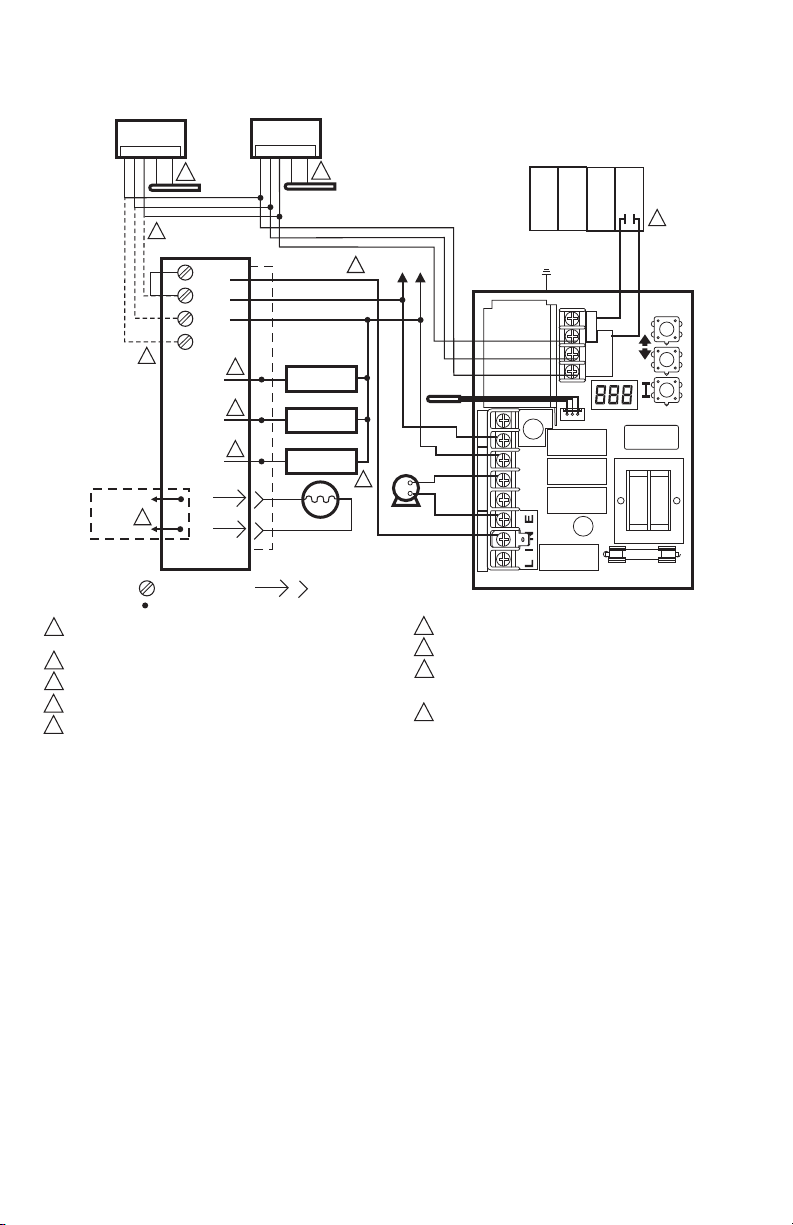
Ó
MÓDULO DE
REINICIO EXTERIOR
50022037-002
CONTROLADORES ELECTRÓNICOS PARA ACEITE L7224A,C; L7248A,C,L AQUASTAT®
DULO PARA AGUA
M
CALIENTE DOMÉSTICA
50022037-002
1 2 3 OT OT
6
8
R7184
T
T
2
1
5
TERMINAL
ENVIRACOM™
AL CIRCUITO
DE
ALARMA
REMOTA
LEYENDA TERMINAL DE TORNILLO
1
SUMINISTRO DE ENERGÍA. PROPORCIONE LOS MEDIOS DE DESCONEXIÓN Y DE
PROTECCIÓN CONTRA SOBRECARGAS SEGÚN SE REQUIERA.
FUNCIÓN OPCIONAL EN MODELOS SELECTOS.
2
3
CONSULTE LA ETIQUETA DEL DISPOSITIVO PARA VER EL CÓDIGO DE COLOR DE LOS CABLES.
LA VÁLVULA ES OPCIONAL EN MODELOS ESPECÍFICOS.
4
EL TERMINAL ENVIRACOM™ 3 TAMBIÉN ES EL PRIMER TERMINAL
5
DEL TERMOSTATO.
MOTOR DEL
QUEMADOR
ENCENDEDOR
VÁLVULA
2
CONEXIÓN DE CABLES SIN SOLDADURA
SENSOR DE
EXTERIORES
C7089U
LIMIT
L1
3
L2
CÉLULA DE
CADMIO
3
3
3
1 2 3 TS TS
SENSOR DE
TEMPERATURA
32003971-003
CÉLULA
DE CADMIO
CAJA DE
EMPALMES
MOTOR DEL
QUEMADOR
ENCENDEDOR
VÁLVULA
7
1
TERMINAL DE CONEXIÓN RÁPIDA
DE 1/4 DE PULGADA (6 MM)
L1 (CON
CORRIENTE)
CIRCULADOR
DE VOLTAJE
4
PANEL DE REPRODUCCIÓN
PARA MÚLTIPLES ZONAS
T T
L2
L7224
T
3
T
2
SENSOR
ZR
L1
DE LÍNEA
L2
C2
B2
C1
B1
ZC
6
MÓDULO DE REINICIO EXTERIOR Y SENSOR DE EXTERIORES OPCIONALES.
7
MÓDULO OPCIONAL PARA AGUA CALIENTE DOMÉSTICA.
8
CONECTE SOLAMENTE LOS TERMINALES ENVIRACOM (1, 2, 3) EN EL CONTROL
PRIMARIO DE ACEITE SI SE CONECTA A UN DISPOSITIVO DE DIAGNÓSTICO REMOTO;
DE LO CONTRARIO, CONECTE UN PUENTE ENTRE LOS TERMINALES TT.
9
LOS TERMINALES DEL PANEL DE ZONA PUEDEN TENER ETIQUETAS DIFERENTES.
VERIFIQUE LAS ESPECIFICACIONES DEL FABRICANTE DEL PANEL PARA OBTENER
INSTRUCCIONES ESPECÍFICAS SOBRE EL CABLEADO.
1
LINE
9
MS32024
Fig. 12. L7224/L7248 con sistema de zonas múltiples con módulos de agua caliente doméstica y de reinicio
exterior (aplicaciones con tanque indirecto).
17 68-0281EFS—06
Page 52
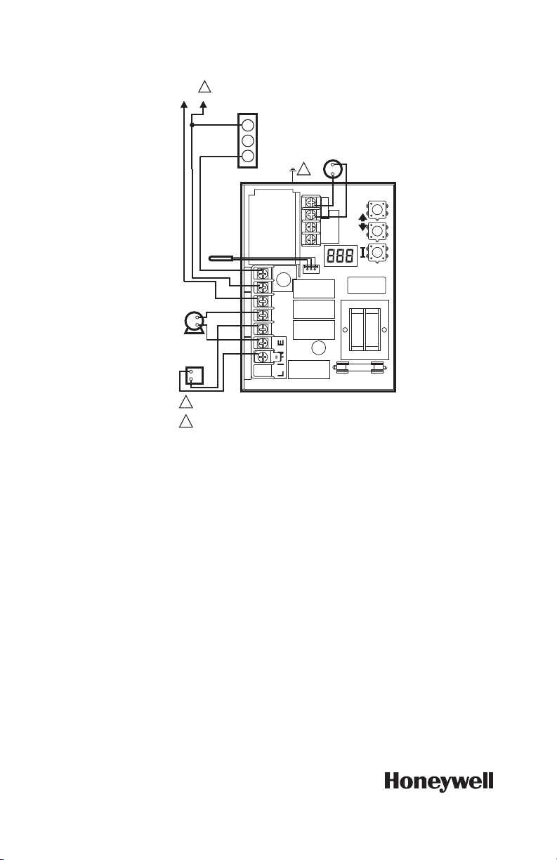
CONTROLADORES ELECTRÓNICOS PARA ACEITE L7224A,C; L7248A,C,L AQUASTAT®
ELL=ON (ENCENDIDO)
1
L2
L1 (CON CORRIENTE)
R
L6006
CONTROLADOR
W
DE LÍMITE MÍNIMO
B
L7248L
SENSOR
ZR
CIRCULADOR
DE VOLTAJE
DE LÍNEA
RELÉ DEL
QUEMADOR DE
ACEITE DE
VOLTAJE DE LÍNEA
1
SUMINISTRO ELÉCTRICO. PROPORCIONE LOS MEDIOS DE DESCONEXIÓN Y DE
PROTECCIÓN CONTRA SOBRECARGAS SEGÚN SE REQUIERA.
2
LA CUBIERTA DEL CONTROL DEBE TENER UNA CONEXIÓN A TIERRA. UTILICE EL
TORNILLO PARA CONEXIÓN A TIERRA INCLUIDO.
L1
L2
C2
B2
C1
B1
ZC
2
LINE
T
T3
2
1
TERMOSTATO
DE BAJO
VOLTAJE
MS27113
Fig. 13. Conexiones para el límite mínimo exterior del L7248L.
Automatización y control desenlace
Honeywell International Inc.
1985 Douglas Drive North
Golden Valley, MN 55422
customer.honeywell.com
® Marca Registrada e n los Estados Unidos
© 2012 Honeywell Inter national Inc. todos
Los Derechos Reservados
68-0281EFS—06 M.S. Rev. 09-12
Impreso en Estados Unidos
 Loading...