

Page 1

L7224 Series
Oil Electronic
Aquastat® Controller
TECHNICIAN’S QUICK REFERENCE GUIDE
The following service procedure provides a quick overview for
L7224 Series Controllers. For more information, refer to form
69-1384.
On the L7224U the High Limit, High Limit Differential, Low Limit,
and Low Limit Differential can be adjusted to the settings
recommended by the boiler OEM.
Adjusting Settings
To discourage unauthorized changing of Aquastat® settings, a
procedure to enter the adjustment mode is required. To enter the
adjustment mode, press the UP, DOWN, and I buttons
simultaneously for three seconds. Press the I button until the
feature requiring adjustment is displayed:
• HL—High Limit.
• LL—Low Limit.
• Ldf—Low Limit differential.
• F - C—°F or °C.
Then press the UP and/or DOWN buttons to move the set point to
the desired value. After 60 seconds without any button inputs, the
control will automatically return to the READ mode.
To use the L7224U in a cold start boiler application, disable the
Low Limit function by pressing the UP arrow button, DOWN arrow
button and I buttons simultaneously for three seconds. Then push
the I button until LL is displayed. Then press the down arrow
button until OFF is displayed.
Display
In the RUN mode, the Aquastat® will flash “bt” (boiler temp)
followed by the temperature (i.e., 220), followed by °F or °C.
To read boiler settings, press the I key to read the parameter of
interest. For example, press I (HL) High Limit is displayed,
followed by a three-digit number, i.e., 220, followed by °F or °C.
69-1957—1
Page 2
L7224 SERIES
Pressing the I button again will display the LL (Low Limit) followed
by a three-digit number and the corresponding degree designator.
See the table below for an explanation of display readout.
After approximately 60 seconds without any key presses, the
display will enter a dim display mode. To return to the bright
display mode, simply press and release any key.
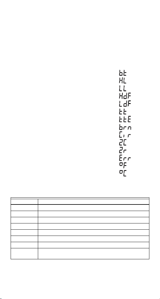
Display
Text Description
bt
f
c
Boiler Temperature
High LimitHL
Low LimitLL
High Limit DifferentialHdf
Low Limit DifferentialLdf
Local Thermostat Statustt
Enviracom Thermostat Statustte
Burner Statusbrn
Circulator Statuscir
Zone ControlZc
Zone RequestZr
Error Codeerr
Degrees Fahrenheit
Degrees Celsius
Shows
M22149
Table 1. LED Error Codes
Error Code Cause/Action
Err1 Sensor fault; check sensor.
Err2 ECOM fault; check EnviraCOM. wiring.
Err3 Hardware fault; replace control.
Err4 B1 fault; check B1 wiring/voltage.
Err5 Low Line; Check L1-L2, 110 Vac.
Err6 Fuse; Check ECOM wires, Replace fuse.
Err7 EEPROM, HL, LL, Hdf, Ldf, Reset to default values.
Err8 Repeated B1 fault (voltage present at B1 when
output is turned off); check B1 wiring/voltage.
69-1957—1 2
Page 3

L7224 SERIES
Table 2. L7224 Controller Operating Sequence
Action System Response
Thermostat
calls for heat.
Circulator starts when water temperature is
above Low Limit setting (if applicable). Boiler
temperature is checked. Burner starts when
water temperature is below High Limit setting.
Boiler exceeds
the High Limit.
Thermostat is
Burner is turned off. Burner restarts when the
water temperature drops below the High Limit
setting minus the differential.
Circulator and burner turn off.
satisfied.
Error conditions
1-5.
Error conditions
6-7.
Error condition 8.If the error condition is detected, all outputs
If an error condition is detected, all outputs
except ZC are shut down. Burner is off. Control
continues to function and restarts when error is
corrected. During the error check sequence, the
system checks for drift in the sensor and
corrosion in the connections.
If error condition 6 or 7 occurs, the control has
reset the High Limit, Low Limit and Differential
Setting to a default setting and will continue to
run at those settings. Performance of the system
will be degraded.
except ZC are shut down. Burner is off. Control
continues to function and restarts when all three
user keys have been pressed longer than 60
seconds.
Troubleshooting
When attempting to diagnose system performance, reference the
LED display to help identify specific areas not working properly.
The LED display will scroll “err”, followed by a digit (1-8). See
Table 1 for a description of the error and suggested actions. See
below for a troubleshooting guide.
Table 3. Troubleshooting Guide
System
Condition
Boiler is
cold,
house is
cold
a
. Refer to Fig. 5 for Display and LED locations.
b
. ZC LED ON indicates ZC terminal power is OFF.
c
. ZC LED OFF indicates ZC terminal power is ON.
Diagnostic
Condition Check Action
Display is OFF 120 Vac system
Display is ON;
TT-LED is OFF
Display is ON;
TT-LED is OFF
power.
24 Vac T-T No 24V; replace
24V present;
disconnect
thermostat,
short T-T
3 69-1957—1
a
.
Turn system power on.
control
Boiler starts, check
wiring and thermostat
Page 4

Table 3. Troubleshooting Guide
System
Condition
Boiler is
cold,
house is
cold
Boiler is
hot, house
is cold
a
. Refer to Fig. 5 for Display and LED locations.
b
. ZC LED ON indicates ZC terminal power is OFF.
c
. ZC LED OFF indicates ZC terminal power is ON.
Diagnostic
Condition Check Action
Display is ON;
TT-LED is ON
B1 LED is ON
Display is ON;
TT-LED is ON
Display is ON;
TT-LED is ON
120 Vac at B1-B2• If no, replace control.
Refer to err on
display
120 Vac at C1-C2• 120 Vac at C1-C2,
C1 LED is ON
Display is ON;
TT-LED is ON
C1 LED is OFF;
ZC LED is ON
Display is ON;
TT-LED is ON
ZC LED is
c
OFF
Boiler below the
Low Limit
temperature,
b
wait for boiler to
go above Low
Limit
temperature.
Boiler above
LL? If yes,
check for 120
Vac between ZC
and L2
a
.
• If yes, check burner
and wiring
—
check wiring to pump
• Wiring ok, is pump
running? If not,
replace the pump.
• If pump is running,
check for trapped air
or closed zone
valves.
• If no 120 Vac,
replace control.
• If yes, check zone
relays, circulators
and wiring.
Automation and Control Solutions
Honeywell International Inc. Honeywell Limited-Honeywell Limitée
1985 Douglas Drive North 35 Dynamic Drive
Golden Valley, MN 55422 Toronto, Ontario M1V 4Z9
customer.honeywell.com
® U.S. Registered Trademark
© 2006 Honeywell International Inc.
69-1957—1 Rev. 06-06
 Loading...