

Page 1
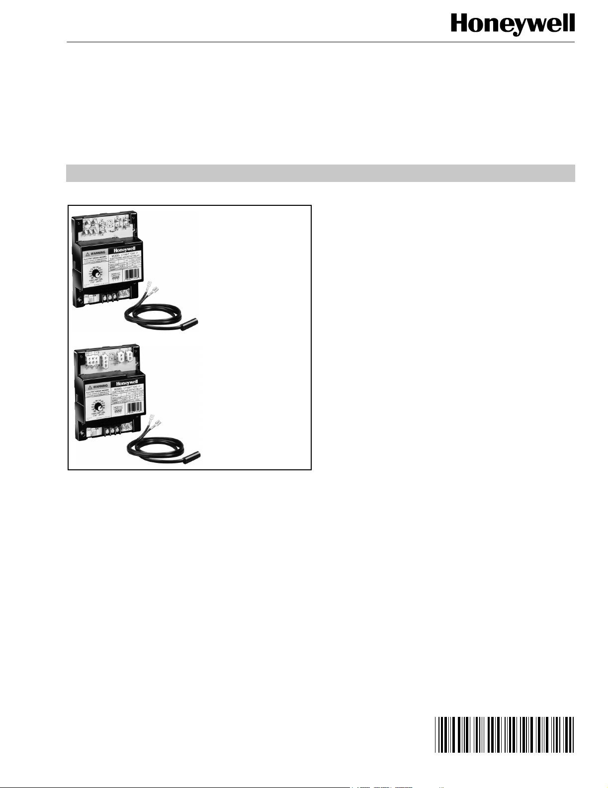
Electronic Aquastat® Controller
L7148F WITH QUICK CONNECTS
(SENSOR NOT INCLUDED)
L7148F WITH PLUG CONNECTIONS
(SENSOR NOT INCLUDED)
L7148F
PRODUCT DATA
FEATURES
• Available with quick connect or AMP® plug
connections. T, TV and Z terminals are provided
in a terminal block with screw connections.
• Vent damper plug optional.
• Separate high limit control not required.
• Software defined minimum/maximum limit settings.
• External 120 Vac to 24 Vac transformer, ordered
separately, is field replaceable and upgradable.
• Patented limit rated 209659A,B,C Sensors are
separately replaceable.
• Communications port for future field added advanced
feature modules.
• Flush mounted to sheet metal rather than spud
mounted to sensing well.
• 3/16 in. (5 mm) B1 quick connect and AMP plug
connections meet ANSI miswiring requirements.
• UL353 Limit Controls approval for both U.S. and
Canada.
• Meets UL 1998 Software Safety Standards.
• Diagnostic LED to assist in system troubleshooting.
GENERAL
The L7148F Electronic Aquastat® Controller is an immersion
type hydronic controller that provides high limit protection
and controls circulator, gas valve and optional vent damper
equipment. The complete L7148F system requires a sensor,
immersion well and transformer, all of which must be ordered
separately. See Table 1 for sensor specifications.
An external 120 Vac to 24 Vac transformer is required to
power the L7148F. For total external transformer VA
requirements, add the 10 VA requirement for the control,
gas valve load requirement (connections B1, B2), zone valve
connection requirement (see zone valve specifications), vent
damper requirement and VA requirement for any other
equipment. Total low voltage load must not exceed 4A.
® U.S. Registered Trademark
Copyright © 2001 Honeywell • All Rights Reserved
Contents
General ............................................................................. 1
Features ........................................................................... 1
Specifications ................................................................... 2
Ordering Information ........................................................ 2
Installation ........................................................................ 3
Adjustment ....................................................................... 5
Operation .......................................................................... 5
Checkout .......................................................................... 11
Troubleshooting ................................................................ 11
68- 0189- 2
Page 2

L7148F ELECTRONIC AQUASTAT® CONTROLLER
(
SPECIFICATIONS
IMPORTANT
The specifications given in this publication do
not include normal manufacturing tolerances.
Therefore, this unit may not exactly match the
listed specifications. Also, this product is tested
and calibrated under closely controlled conditions,
and some minor differences in performance can be
expected if those conditions are changed.
Standard Models
Models:
L7148F Electronic Aquastat Controller with quick
connect terminals, with or without vent damper plug
and communications port (for adding advanced feature
modules).
L7148F Electronic Aquastat Controller with AMP plug
connections, with or without vent damper plug and
communications port (for adding advanced feature
modules). AMP connector on wiring board for
transformer connection.
3/8
10)
4 (102)
4-11/16 (119)
7/16 (11)
4-1/2
(114)
1-3/16
(30)
6
(152)
1/2
(13)
1-5/8
(41)
(16)
M11500
5/8
High Limit Setpoint Range: 130°F to 240°F
(54°C to 116°C). (Select models may be different.)
Differential: Fixed 10°F (6°C). (Select models may
be different.)
Operating Voltage Range:
L1-L2 Line Voltage Power: Nominal, 120 Vac.
R-C 24V Transformer Output: Nominal, 24 Vac.
Minimum/Maximum Ambient Temperature:
-30°F (-9°C) with 2.0A 24V load.
150°F (66°C) with 2.0A 24V load.
Operating Relative Humidity: 0 to 95% RH non-condensing.
Electrical Ratings (60 Hz only):
B1-B2: 2.0A at 24 Vac.
C1-C2: Full Load 7.4A at 120 Vac; Locked Rotor,
44.4A at 120 Vac.
NOTE: Total Low Voltage load must not exceed 4.0A.
Case Dimensions: See Fig. 1.
ORDERING INFORMATION
Fig. 1. L7148F dimensions in in. (mm).
Mounting: Vestibule mount.
Approvals:
Underwriters Laboratories Inc. Component Recognized:
File No. MP466.
Canadian Underwriters Laboratories Inc. Component
Recognized: File No. MP466.
ANSI Miswiring: 3/16 in. (5 mm) B1 quick connect terminal
and AMP® plug connections meet ANSI Appliance
Miswiring Standard.
Material Safety Data Sheets (MSDS): For more information
on heat-conductive compound, see form 69-0955.
Accessories:
107408 Heat Conductive Compound (4 oz. can). For more
information, see form 69-0955, Heat Conductive
Compound.
121371AA Sensor Retaining Clamp.
32002656-001 Sensor Retaining Spring.
Sensor: Sensor available separately. For leadwire lengths
available, see Table 1.
When purchasing replacement and modernization products from your TRADELINE® wholesaler or distributor, refer to the
TRADELINE® Catalog or price sheets for complete ordering number.
If you have additional questions, need further information, or would like to comment on our products or services, please write or
phone:
1. Your local Home and Building Control Sales Office (check white pages of your phone directory).
2. Home and Building Control Customer Relations
Honeywell, 1885 Douglas Drive North
Minneapolis, Minnesota 55422-4386
In Canada—Honeywell Limited/Honeywell Limitée, 35 Dynamic Drive, Scarborough, Ontario M1V 4Z9.
International Sales and Service Offices in all principal cities of the world. Manufacturing in Australia, Canada, Finland, France,
Germany, Japan, Mexico, Netherlands, Spain, Taiwan, United Kingdom, U.S.A.
68-0189—2 2
Page 3
L7148F ELECTRONIC AQUASTAT® CONTROLLER
Immersion Well: Available separately. Contact your
distributor or Honeywell sales representative to order, or
refer to Accessories for Immersion Wells, Compression
Fittings, and Element Holders, form 68-0040.
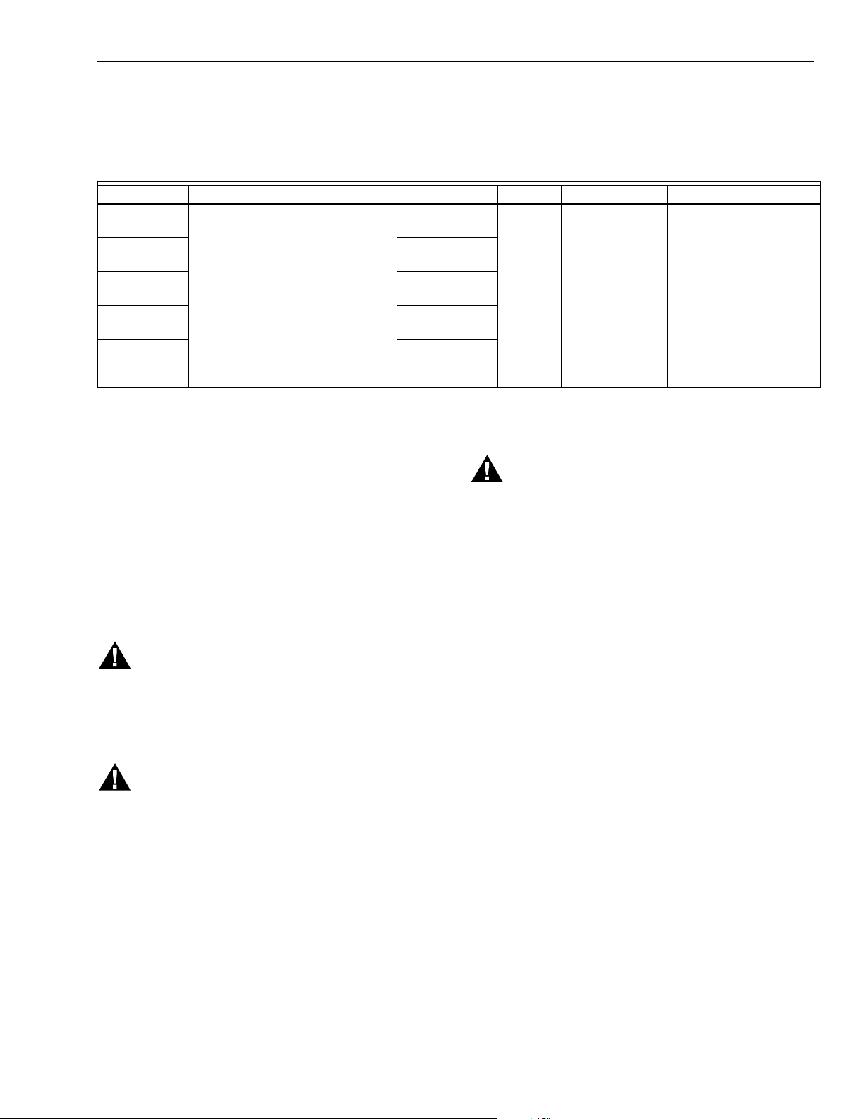
Table 1. Sensor Specifications.
Sensor Termination Lead Length Diameter Capsule Length Mounting Material
32004955-001 One 1/4 in. (6 mm) and one 3/16 in.
(5 mm) quick connect terminal.
32004955-002 18 in. (458 mm),
32004955-003 25 in. (610 mm),
32004955-004 36 in. (914 mm),
32004955-005 48 in. (1219
12 in. (304 mm),
18 gauge wire.
18 gauge wire
18 gauge wire.
18 gauge wire
mm), 18 gauge
wire.
INSTALLATION
When Installing this Product…
1. Read these instructions carefully. Failure to follow
them could damage the product or cause a hazardous
condition.
2. Check the ratings given in the instructions and on the
product to make sure the product is suitable for your
application.
3. Installer must be a trained, experienced service
technician.
4. After installation is complete, check out product
operation as provided in these instructions.
WARNING
Fire or Explosion Hazard.
Can cause property damage, severe injury or
death.
Use this product only in systems with a pressure
relief valve.
WARNING
Electrical Shock Hazard.
Can cause electrical shock or equipment damage.
Disconnect power supply before beginning wiring.
Never apply a jumper across (or short) terminals
B1 and B2. This will burn out the transformer.
Transfo rmer: Available separately with either quick connect
terminals or AMP plug connections. Contact your
distributor or Honeywell sales representative to order.
3/8 in.
(10 mm)
1-1/4 in.
(32 mm)
Compression Thermal
Mounting
WARNING
Fire or Explosion Hazard.
Can cause serious injury, death or property
damage.
Sensor must be fully inserted to bottom of well.
IMPORTANT
Sensor and immersion well are not provided and must be
purchased separately. Mounting screws must be obtained
locally. See Table 1 for sensor specifications. The sensor
is adaptable to existing immersion wells with a shell I.D. of
3/8 in. (10 mm). To order an immersion well, contact your
distributor or Honeywell sales representative, or refer to
Accessories for Immersion Wells, Compression Fittings,
and Element Holders, form 68-0040.
In new and replacement applications, mount the Electronic
Aquastat Controller on the vestibule away from heated
surfaces. Use four no. 6 screws, obtained locally, to mount
the control through the four mounting holes.
Mount the immersion well, purchased separately, where boiler
water of average temperature can circulate freely around it.
To insert the immersion well into the boiler:
The L7148F is not designed for spud mounting to the
sensing well.
1. Turn off all power and drain the boiler.
2. If no tapping is provided, prepare properly sized and
threaded tapping near the top of the boiler.
3. Coat the well threads sparingly with pipe dope, install
the well in the boiler tapping, and tighten securely.
4. Refill the boiler and check for water leakage.
plastic
3 68-0189—2
Page 4
L7148F ELECTRONIC AQUASTAT® CONTROLLER
R
4
IMPORTANT
• Sensor must be fully inserted to bottom of well.
• Remove all heat conductive compound from the well
prior to sensor insertion.
5. Insert the sensor into the well. Make sure the sensor fits
securely against the bottom of the well.
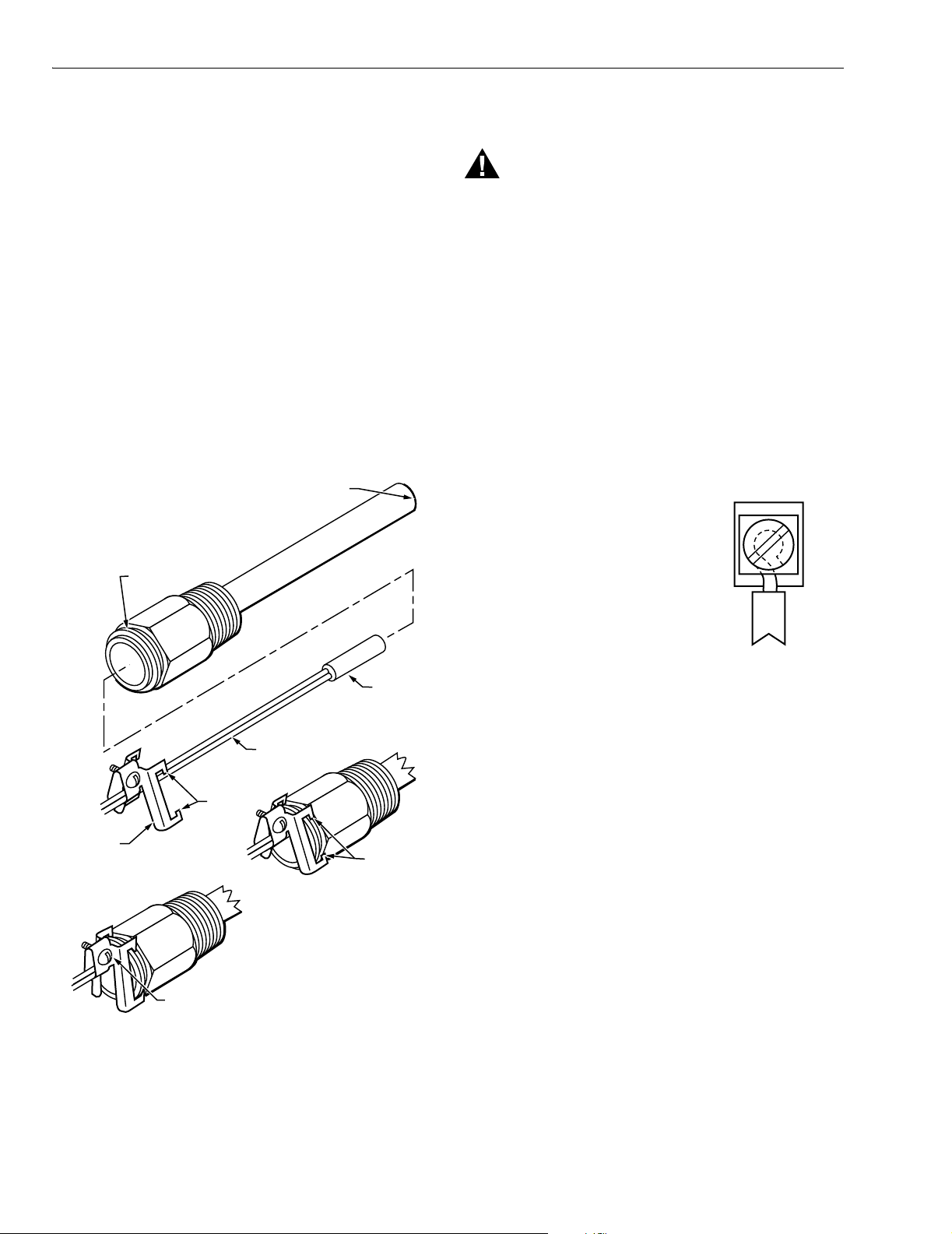
To secure sensor and leadwire with mounting clamp
(see Fig. 2.):
1. Loosen the draw nut and spread the jaws of the clamp.
2. Slide the jaws of the clamp over the mounting flange.
3. Adjust the sensor leadwire to fit through the groove in
the mounting clamp.
IMPORTANT
Do not overtighten the draw nut or a system
shut-down could occur.
4. Tighten the draw nut so that the clamp is firmly attached
to the well and the leadwire is held securely in place.
5. Secure excess leadwire to prevent disconnection of
sensor or removal from the well.
BOTTOM OF WELL
MOUNTING
FLANGE
Wiring
WARNING
Electrical shock hazard.
Can cause serious injury, death or equipment
damage.
Disconnect power supply before beginning wiring.
IMPORTANT
• An external transformer is required for operation.
The user must size the transformer for the specific
application.
• If L7148F is used to power zone valves, total low
voltage (24V) load must not exceed 4A. Use a
zoning panel such as the Honeywell R8889 when
load exceeds these ratings.
All wiring must comply with local electrical codes and
ordinances. Refer to the SPECIFICATIONS section when
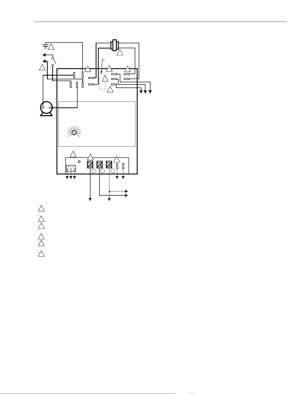
applying this control. For appropriate wiring diagrams, see
Fig. 3 through 10.
For screw terminal connections:
1. Strip 1/16 in. of insulation from the
wire end.
2. Insert the wire under the terminal
screw and contact plate.
3. Using a standard, flat-headed
screwdriver, tighten the screw until
the wire is firmly in contact with the
screw and contact plate.
4. Tighten the screw an additional
one-half turn.
M1148
SENSO
SENSOR
LEADWIRE
JAWS OF
CLAMP
CLAMP
MOUNTING FLANGE
TIGHTEN SCREW AND DRAW NUT
TO SECURE CLAMP
PLACE
JAWS OF
CLAMP OVER
M11483
Fig. 2. Secure sensor and leadwire with mounting
clamp or spring (see Accessories).
For quick connect terminal connections:
Connect the quick connect to the appropriate terminal on
the control. B1 and S1 are 3/16 in. (5 mm) quick connect
terminals; all other terminals are 1/4 in. (6 mm).
For AMP plug connections:
Connect the AMP plugs to the receptacles on the control.
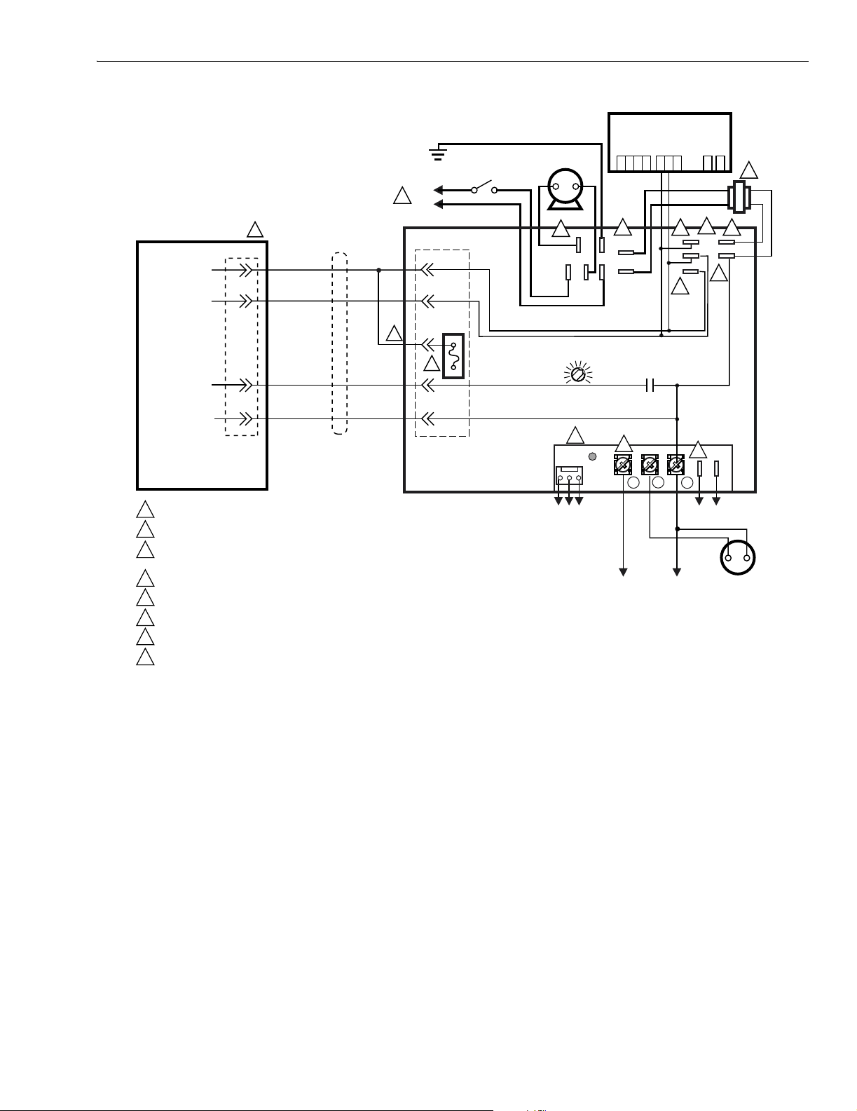
An AMP plug connection is shown in Fig. 8.
The L7148F and appropriately sized external transformer can
power up to three Honeywell V8043 Zone Valves. Additional
valves, in groups of three or less, require an additional
transformer, or use Honeywell R8889 Zone Valve Panel.
Follow the appropriate wiring diagrams when using zone
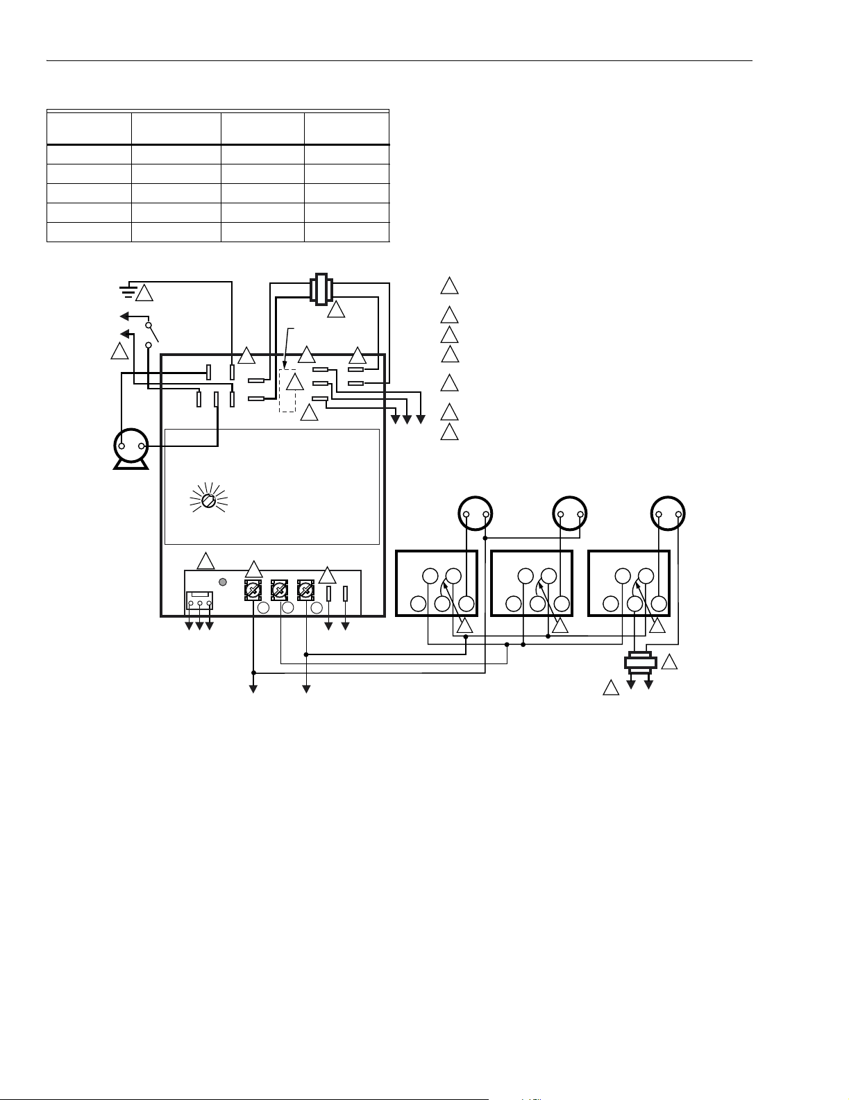
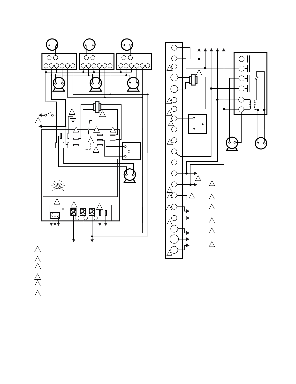
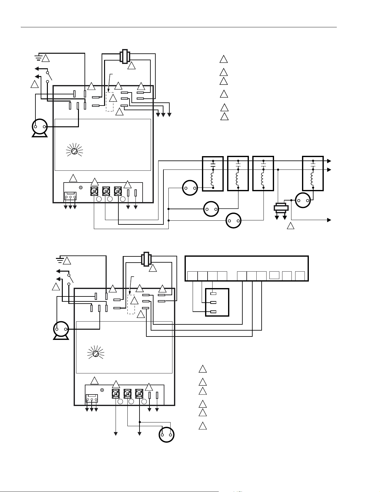
valves. See Fig. 4, 5, 7, and 9.
On systems requiring a vent damper, the Honeywell vent
damper can be connected directly to some L7148F Electronic
Aquastat models (Fig. 9) or S8610 Spark Ignition Modules
(Fig.8). With the vent damper plugged into the Electronic
Aquastat Controller, a fuse in the Electronic Aquastat
Controller blows when the thermostat first closes. Once
the fuse is blown, the Electronic Aquastat Controller does
not operate unless the vent damper is connected. With the
vent damper plugged into the S8610, a fuse in the ignition
module blows when first powered. Once the fuse is blown,
the ignition module does not operate unless the vent damper
is connected.
68-0189—2 4
Page 5
L7148F ELECTRONIC AQUASTAT® CONTROLLER
C
L
L
OPERATION
A system containing an L7148F Electronic Aquastat does
not require a separate high limit controller. The L7148F can
replace a Honeywell L4080 High-Limit Controller and an
R8225 Transformer. The L7148F does not provide a low limit
function. An external transformer, appropriately sized for the
specific application; a sensor, and an immersion well are
required for Aquastat¨ operation.
In the L7148F system without an advanced feature module,
the circulator is on any time there is a thermostat call for
heat. The addition of an advanced feature module may alter
operation. The burner is also on during a thermostat call for
heat unless the boiler water temperature exceeds the high
limit setting.
The L7148F Electronic Aquastat has three states of operation:
2
L1
L2
1
IRCULATOR
DISCONNECT
SWITCH
L7148F
CIRC
C2
L1
L2X
L1X
4
G
C1
L2X
L1X
L2
3
R
C
5
OPTIONAL VENT
DAMPER PLUG
4
C
B2
B1
R
R
6
4
COM
BURNER
CONTRO
24V HOT
TO VALVE
OR
IGNITION
CONTRO
normal, high-limit and reset: (The control moves back and
forth between the normal and high-limit states, as needed.
HIGH LIMIT DIAL
However, the control only enters the reset state when there
is an abnormal condition such as an internal error or shorted
sensor.)
4
COM
DATA
PORT
TO ADVANCED
FEATURE
MODULE
1
POWER SUPPLY. PROVIDE DISCONNECT MEANS
AND OVERLOAD PROTECTION AS REQUIRED.
2
GROUND MUST BE AN EARTH GROUND CONNECTION.
B1 AND S1 ARE 3/16 IN. QUICK CONNECT TERMINALS.
3
ALL OTHER TERMINALS ARE 1/4 IN.
C, COM, Z, B2, G ARE ALL CONNECTED INSIDE DEVICE.
4
5
FOR EXTERNAL TRANSFORMER VA REQUIREMENTS,
REFER TO APPLICA TION SECTION.
6
R IS A CONVENIENCE TERMINAL FOR 24V HOT
CONNECTION FOR USE WITH IGNITION CONTROLS.
4
C
THERMOSTAT
STATUS
W
R
TO BOILER
SENSOR
24VCOM
3
S1 S2
TO THERMOSTAT
OR SWITCH
CLOSURES
FOR ZONES
M17967
1. Normal: The control enters the normal state when the
temperature of the boiler drops below the high limit
setting minus 10°F (-12°C). The control exits the normal
state and returns to the high limit state when the
temperature of the boiler exceeds the high limit setting.
2. High limit: The control enters the high limit state when
the temperature of the boiler exceeds the high limit
setting. The control exits the high limit state and returns
to the normal state when the temperature of the boiler
drops to the high limit setting minus 10°F (-12°C).
3. Reset: Detects an error condition such as an open
sensor and shuts down all outputs. The control
continues to function and automatically restarts if the
error condition is corrected.
High Limit
The high-limit switch shuts off the burner (B1, B2 output) when
the boiler water temperature exceeds the high-limit setting.
Because heating systems differ, the correct temperature
setting for each system can vary. Follow the boiler
manufacturer recommendations for the proper setting. Turn
Fig. 3. External connections for L7148F.
the HIGH-LIMIT dial on the control until the desired setting is
directly below the indicator.
ADJUSTMENT
A manual adjustment potentiometer is used to set the high
limit controller. At the maximum setpoint of 240°F (116°C), the
calibration tolerance is plus 10°F (6°C) and minus 15°F (8°C).
(Meets ASME and UL353 Standards).
(Select models available with other ranges.)
NOTE: Setpoint Range: 130°F (54°C) to 240°F (116°C).
Differential: Fixed at 10°F (6°C).
Sequence of Operations
The state of the burner and circulator outputs are dependent
on the thermostat input mode (On/Off) and the current
operation mode (High limit/Normal/Reset). See Table 2
Sequence of Operations.
NOTE: Table 2 applies only to the operation of the Electronic
Aquastat Controller without an advanced feature
module. Advanced feature modules provide
additional functions such as boiler temperature
display and outdoor reset of high limit. Changes in
output states and operation modes caused by these
additional functions are not included.
5 68-0189—2
Page 6
L7148F ELECTRONIC AQUASTAT® CONTROLLER
.
L
L
Table 2. Sequence of Operation
Operation
Thermostat
Mode Burner Circulator
Off Normal Off Off
Off High Limit Off Off
On Normal On On
On High Limit Off On
Either Reset Off Off
L2X
L2X
L1X
6
L1X
5
C
W
2
1
2
1
DISCONNECT
SWITCH
L7148F
C2
L1
HIGH LIMIT DIAL
6
DATA
PORT
TO ADVANCED
FEATURE
MODULE
6 6
G
C1
L2
COM
THERMOSTAT
STATUS
R
C
4
OPTIONAL VENT
DAMPER PLUG
6
C
B2
B1
R
R
7
5
S1 S2
R
TO BOILER
SENSOR
COM
BURNER
CONTROL
24V HOT
TO V ALVE
OR
IGNITION
CONTROL
V8043F
END SWITCH
TH-TR
1
POWER SUPPLY. PROVIDE DISCONNECT MEANS
AND OVERLOAD PROTECTION AS REQUIRED.
2
GROUND MUST BE AN EARTH GROUND CONNECTION.
ADD JUMPER AS SHOWN.
3
FOR EXTERNAL TRANSFORMER VA REQUIREMENTS,
4
REFER TO APPLICATION SECTION.
5
B1 AND S1 ARE 3/16 INCH. QUICK CONNECT TERMINALS
ALL OTHER TERMINALS ARE 1/4 INCH.
6
C, COM, Z, B2, G ARE ALL CONNECTED INSIDE DEVICE.
7
R IS A CONVENIENCE TERMINAL FOR 24V HOT
CONNECTION FOR USE WITH IGNITION CONTROLS.
T87F
ZONE 1
TH
TR
3
T87F
ZONE 2
V8043F
END SWITCH
TH-TR
V8043F
END SWITCH
TH-TR
TH
TR
3
T87F
ZONE 3
TH
TR
3
4
1
L2
M11475B
24VCOM
(HOT)
L1
Fig. 4. Wiring L7148F with multizone valves.
68-0189—2 6
Page 7
L7148F ELECTRONIC AQUASTAT® CONTROLLER
L
L7148F
T87F
R845 RELAY
TT
4
C1
C2
COM
6
5
PUMP PUMP
2
4 4
G
L2X
L1X
L2
4
C
THERMOSTAT
STATUS
1
23
PUMP
DISCONNECT
SWITCH
L1
1
2
L7148F
L1
HIGH LIMIT DIAL
4
1
2
3
4
5
6
DATA
PORT
TO ADVANCED
FEATURE
MODULE
POWER SUPPLY. PROVIDE DISCONNECT MEANS AND OVERLOAD
PROTECTION AS REQUIRED.
GROUND MUST BE AN EARTH GROUND CONNECTION.
B1 AND S1 ARE 3/16 INCH QUICK CONNECT TERMINALS. ALL OTHER
TERMINALS ARE 1/4 INCH.
C, COM, Z, B2, G ARE ALL CONNECTED INSIDE DEVICE.
FOR EXTERNAL TRANSFORMER VA REQUIREMENTS, REFER TO
APPLICATION SECTION.
R IS A CONVENIENCE TERMINAL FOR 24V HOT CONNECTION FOR
USE WITH IGNITION CONTROLS.
TT
1
23
L2X
L1X
W
3
24VCOM
T87F
R845
4
6
5
R
C
5
OPTIONAL VENT
DAMPER PLUG
4
C
B2
B1
R
R
6
3
S1 S2
R
TO BOILER
SENSOR
TT
1
23
LOW
VOLTAGE
GAS VALVE
(VR8300)
CIRCULATOR
TR
TH
T87F
THTR
4
M11477B
5
R845
6
R
W
C
4
L2X
L1X
C
4
R
3
B2
4
B1
R
6
C1
C2
L1
L2
2
G
4
S1
3
S2
1
24V
DATA
COM
4
Fig. 6. Wiring L7148F in multizone system
TO ADDITIONAL R845A
RELAYS FOR OTHER ZONES
5
TR
THTR
TH
LOW VOLTAGE
GAS VALVE
(VR8300)
L1
(HOT)
1
1
L2
2
TO
BOILER
SENSOR
TO
ADVANCED
FEATURE
MODULE
POWER SUPPLY. PROVIDE DISCONNECT
MEANS AND OVERLOAD PROTECTION
AS REQUIRED.
2
GROUND MUST BE AN EARTH
GROUND CONNECTION.
3
B1 AND S1 ARE 3/16 INCH QUICK
CONNECT TERMINALS. ALL OTHER
TERMINALS ARE 1/4 INCH.
4
C, COM, Z, B2, G ARE ALL CONNECTED
INSIDE DEVICE.
5
FOR EXTERNAL TRANSFORMER
VA REQUIREMENTS, REFER TO
APPLICATION SECTION.
6
R IS A CONVENIENCE TERMINAL
FOR 24V HOT CONNECTION FOR
USE WITH IGNITION CONTROLS.
R845A RELAY ZONE 1
6
5
4
3
1
2
CIRCULATOR
ZONE 1
with R845 Switched Circulator.
24V
THERMOSTAT
M11481B
Fig. 5. Wiring L7148F in a gas-fired, forced hot
water, tankless, zoned, pump system.
7 68-0189—2
Page 8
L7148F ELECTRONIC AQUASTAT® CONTROLLER
.
C
.
C
2
L1
L2
1
IRCULATOR
DISCONNECT
SWITCH
L7148F
C2
L1
HIGH LIMIT DIAL
5
DATA
PORT
TO ADVANCED
FEATURE
MODULE
5 5
G
C1
L2X
L1X
L2
COM
5
C
STATUS
THERMOSTAT
W
Fig. 7. Typical three-wire zone valve hookup diagram.
L2X
L1X
3
OPTIONAL VENT
DAMPER PLUG
5
B2
B1
4
R
6
4
S1 S2
R
TO BOILER
SENSOR
R
C
C
R
COM
BURNER
CONTROL
24V HOT
TO V ALVE
OR
IGNITION
CONTROL
T87
ZONE 1
T87
ZONE2
1
POWER SUPPLY. PROVIDE DISCONNECT MEANS
AND OVERLOAD PROTECTION AS REQUIRED.
2
GROUND MUST BE AN EARTH GROUND CONNECTION.
FOR EXTERNAL TRANSFORMER VA REQUIREMENTS,
3
REFER TO APPLICATION SECTION.
4
B1 AND S1 ARE 3/16 INCH. QUICK CONNECT TERMINALS
ALL OTHER TERMINALS ARE 1/4 INCH.
C, COM, Z, B2, G ARE ALL CONNECTED INSIDE DEVICE.
5
R IS A CONVENIENCE TERMINAL FOR 24V HOT
6
CONNECTION FOR USE WITH IGNITION CONTROLS.
3
2
1
T87
ZONE 3
3
2
1
3
2
1
120V
(HOT)
L1
L2
1
T87
ZONE 4
3
2
1
M17972
L2X
L2X
L1X
6
L1X
5
C
W
2
L1
L2
1
IRCULATOR
DISCONNECT
SWITCH
L7148F
C2
L1
HIGH LIMIT DIAL
6
DATA
PORT
TO ADVANCED
FEATURE
MODULE
6 6
G
C1
L2
COM
THERMOSTAT
STATUS
R
C
4
OPTIONAL VENT
DAMPER PLUG
6
C
B2
B1
R
R
6
5
S1 S2
R
TO BOILER
SENSOR
24VCOM
S8610
MV MV/PV PV
THERMOSTAT
VENT
DAMPER
PLUG
GND
(BURNER)
VR8304
1
POWER SUPPLY. PROVIDE DISCONNECT MEANS
AND OVERLOAD PROTECTION AS REQUIRED.
2
GROUND MUST BE AN EARTH GROUND CONNECTION.
B1 AND S1 ARE 3/16 INCH QUICK CONNECT TERMINALS
3
ALL OTHER TERMINALS ARE 1/4 INCH.
C, Z, B2, G ARE ALL CONNECTED INSIDE DEVICE.
4
5
FOR EXTERNAL TRANSFORMER VA REQUIREMENTS,
REFER TO APPLICA TION SECTION.
R IS A CONVENIENCE TERMINAL FOR 24V HOT
6
CONNECTION FOR USE WITH IGNITION CONTROLS.
PV
PV
MV
MV
24V
GND
24V TH-W
SPARK
M11478B
Fig. 8. Wiring L7148F with S8610 Intermittent Pilot Ignition Module with automatic
vent damper plug and Honeywell D892/D896/M892/M896 Vent Damper.
68-0189—2 8
Page 9
L7148F ELECTRONIC AQUASTAT® CONTROLLER
S8600
24V GND
DISCONNECT
SWITCH
L1
1
L2
CIRCULATOR
24V
L2X
L1X
8
R
C
4
D892/D896/M892/M896
4
3
2
1
POLARIZED 4-PRONG
MALE MOLEX PLUG AND
4-PRONG FEMALE
MATING PLUG ON CABLE
1
POWER SUPPLY. PROVIDE DISCONNECT MEANS AND OVERLOAD PROTECTION AS REQUIRED.
2
REMOVE PLUG-IN THAT JUMPERS PINS 2 AND 3 WHEN USING VENT DAMPER.
AFTER VENT DAMPER IS PLUGGED INTO L7148F, FUSE BLOWS WHEN THERMOSTAT FIRST
3
CLOSES. AFTER FUSE BLOWS, L7148F OPERATES ONLY WHEN VENT DAMPER IS CONNECTED.
4
SEE VENT DAMPER PRODUCT SPECIFICATIONS FOR INTERNAL SCHEMATICS.
5
S1 IS A 3/16 INCH QUICK CONNECT TERMINAL; S2 IS 1/4 INCH.
6
THIS DEVICE HAS AMP© PLUGS.
7
C, COM, Z, B2, G ARE ALL CONNECTED INSIDE DEVICE.
8
FOR EXTERNAL TRANSFORMER VA REQUIREMENTS, REFER TO APPLICATION SECTION.
CABLE
L7148F
4
2
2
FUSE
3
3
5
1
6-PRONG FEMALE MOLEX
RECEPTACLE IN L7148F
AND 5-PRONG MALE
MOLEX PLUG ON CABLE
6
C1
C2
L1
L2
HIGH LIMIT DIAL
7
COM
DATA
PORT
STATUS
TO ADVANCED
FEATURE
MODULE
7
G
L2X
L1X
HIGH LIMIT CONTACTS
7
C
THERMOSTAT
W
6
7 7
B2
B1
R
3
5
S1 S2
R
TO BOILER
SENSOR
24VCOM
THERMOSTAT
C
R
6
M11480B
Fig. 9. Wiring L7148F with AMP plug connections and internal plug directly to
D892/D896/M892/M896 Vent Damper in hydronic intermittent pilot system.
9 68-0189—2
Page 10
L7148F ELECTRONIC AQUASTAT® CONTROLLER
V
C
L7148F
R
W
C
6
L2X
L1X
C
6
R
TO
ALVE OR
IGNITION
ONTROL
7
6
5
6
B1
6
B2
R
C1
C2
L1
L2
G
S1
S2
24V
DATA
COM
3
5
L1
(HOT)
1
L2
2
TO
BOILER
SENSOR
TO
ADVANCED
FEATURE
MODULE
T87F
ZONE 1
R882C
N.O.
N.C.
COM.
N.O.
N.C.
COM.
BW
W
CIRCULATOR
ZONE 1
1
POWER SUPPLY. PROVIDE DISCONNECT MEANS AND
OVERLOAD PROTECTION AS REQUIRED.
2
GROUND MUST BE AN EARTH GROUND CONNECTION.
FOR EXTERNAL TRANSFORMER VA REQUIREMENTS,
3
REFER TO APPLICA TION SECTION.
4
R882C IS PROVIDED WITH NEC CLASS 1 ENCLOSURE.
5
B1 AND S1 ARE 3/16 INCH QUICK CONNECT TERMINALS.
ALL OTHER TERMINALS ARE 1/4 INCH.
C, COM, Z, B2, G ARE ALL CONNECTED INSIDE DEVICE.
6
R IS A CONVENIENCE TERMINAL FOR 24V HOT CONNECTION
7
FOR USE WITH IGNITION CONTROLS.
T87F
ZONE 2
R882C
N.O.
N.C.
COM.
N.O.
N.C.
COM.
BW
CIRCULATOR
ZONE 2
T87F
ZONE 3
R882C
N.O.
N.C.
COM.
N.O.
N.C.
COM.
B
3 4
CIRCULATOR
ZONE 3
4
M11482B
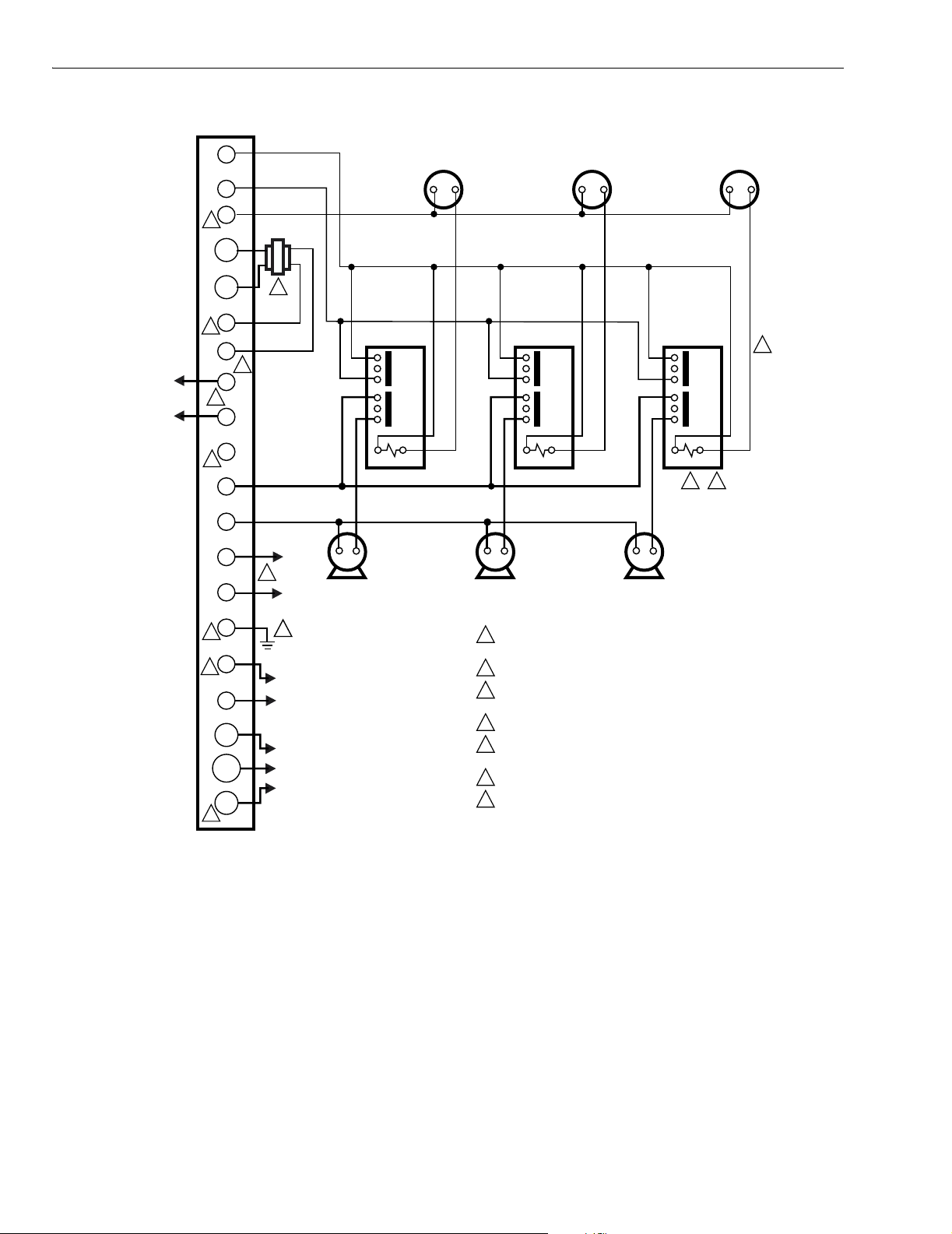
Fig. 10. Multizone system with R882C Switched Circulator.
68-0189—2 10
Page 11
L7148F ELECTRONIC AQUASTAT® CONTROLLER
24VCOM
C
2
L1
L2
1
IRCULATOR
DISCONNECT
SWITCH
L7148F
C2
L1
HIGH LIMIT DIAL
6
DATA
PORT
TO ADVANCED
FEATURE
MODULE
6 6
G
C1
L2X
L1X
L2
COM
6
C
THERMOSTAT
STATUS
L2X
L1X
OPTIONAL VENT
DAMPER PLUG
6
B2
B1
5
R
6
5
R
W
TO BOILER
SENSOR
R
C
4
C
R
S1 S2
TO THERMOSTAT
OR SWITCH
CLOSURES
FOR ZONES
PILOT BURNER
GROUND
(THROUGH
PILOT TUBING)
1
2
3
4
5
6
SV9501/SV9502;
SV9601/SV9602
24 VOLT
COMMON
24 VOLT
THERMOSTAT OR
PRESSURE SWITCH
POWER SUPPLY. PROVIDE DISCONNECT MEANS
AND OVERLOAD PROTECTION AS REQUIRED.
GROUND MUST BE AN EARTH GROUND CONNECTION.
B1 AND S1 ARE 3/16 INCH QUICK CONNECT TERMINALS.
ALL OTHER TERMINALS ARE 1/4 INCH.
C, Z, B2, G ARE ALL CONNECTED INSIDE DEVICE.
FOR EXTERNAL TRANSFORMER VA REQUIREMENTS,
REFER TO APPLICA TION SECTION.
R IS A CONVENIENCE TERMINAL FOR 24V HOT
CONNECTION FOR USE WITH IGNITION CONTROLS.
24 VOLT
HOT
EFT
OUTPUT
M11479B
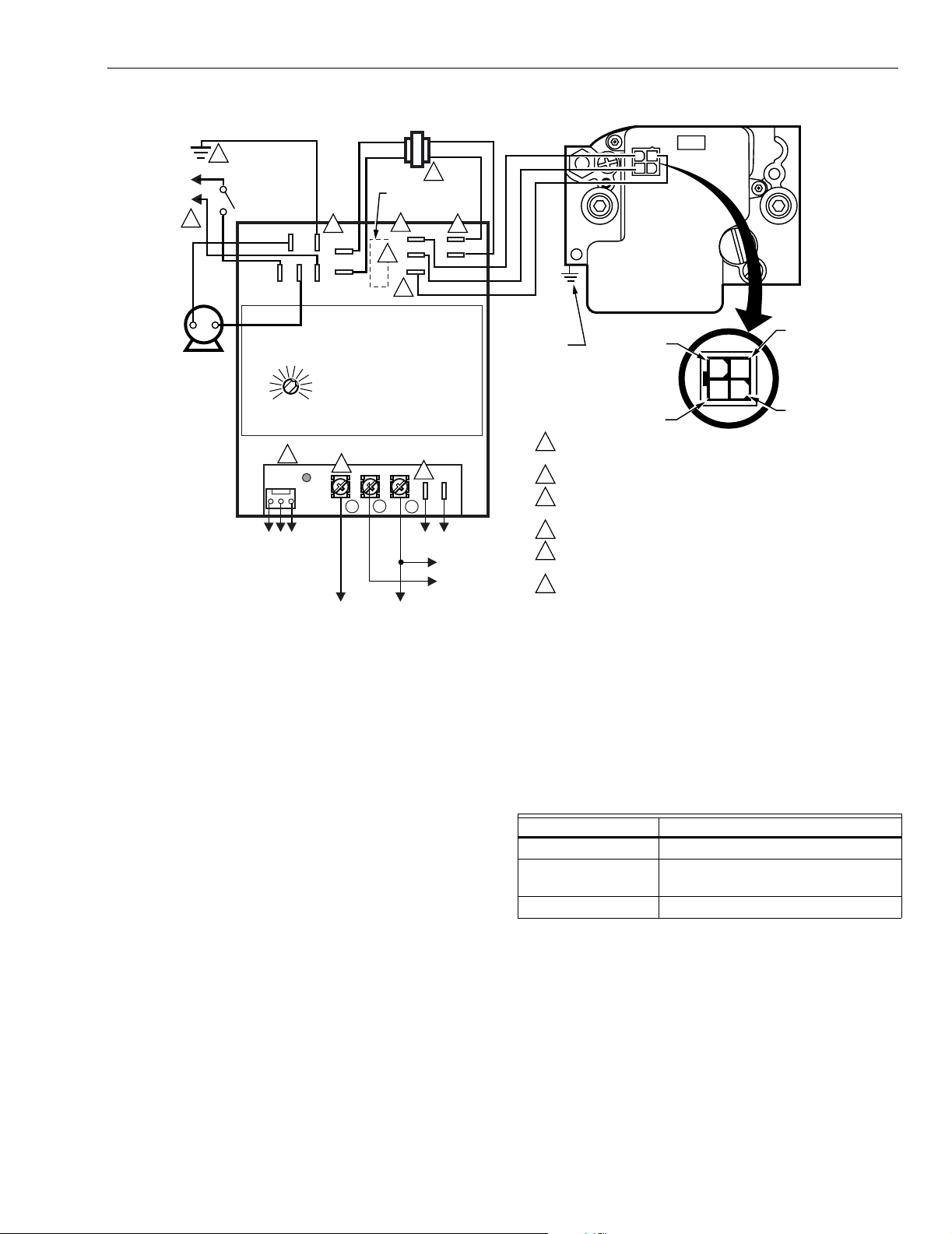
Fig. 11. Wiring L7148F with SV9501/SV9502/SV9601/SV9602 SmartValve™ System Controls.
CHECKOUT
Check to make certain that the Electronic Aquastat Controller
has been properly installed and adjusted. Put the system
into operation and observe the action of the device through
several cycles to make certain that it provides proper control
TROUBLESHOOTING
When attempting to diagnose system performance,
reference to the diagnostic LED can help to identify specific
areas not working properly. Table 3 shows the LED codes.
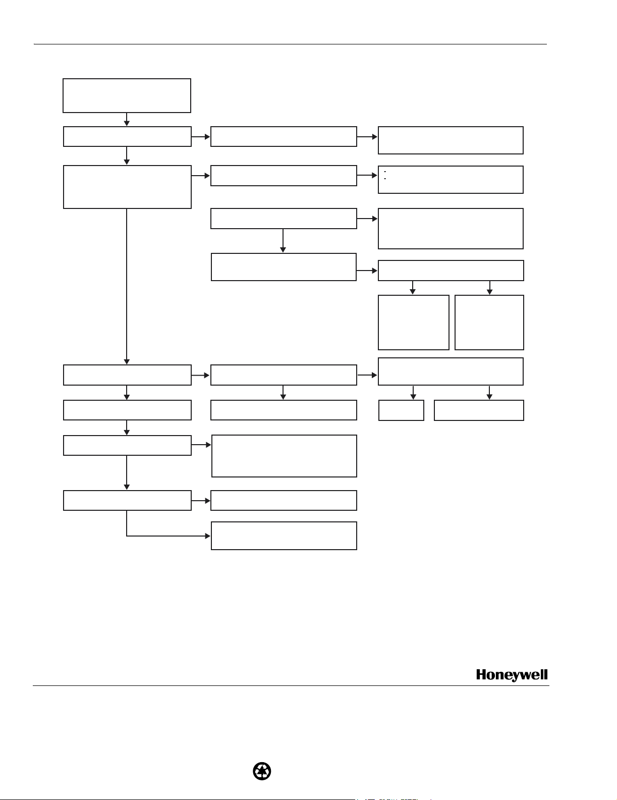
Fig. 12 provides a troubleshooting chart.
of the system as described in the Operation section.
Table 3. LED Codes.
Number of Blinks Indication
Constant On Power on—normal operation.
2 Sensor error—check connection
and/or replace sensor.
3 or 4 L7148F failures—replace control
11 68-0189—2
Page 12
L7148F ELECTRONIC AQUASTAT® CONTROLLER
START
BOILER IS COLD.
BOILER IS NOT REACHING PROPER
TEMPERATURE OR WILL NOT TURN ON.
CHECK: L7148F DIAGNOSTIC LED ON?
YES
SET ROOM THERMOSTAT AT 10 DEGREES
ABOVE ROOM TEMPERATURE.
SET BOILER 10 DEGREES (OR MORE)
ABOVE CURRENT WATER TEMPERATURE.
BOILER TURNS ON?
YES
CHECK: CIRCULATOR PUMP RUNNING?
YES
BOILER SHUTS OFF AT
HIGH LIMIT SETTING?
NO
BOILER SHUTS OFF ABOVE
HIGH LIMIT SETTING?
NO
(BELOW HIGH LIMIT)
NO
CHECK FOR 120 VAC AT L1X, L2X.
CHECK FOR 24 VAC AT R, C.
NO
SHORT TERMINALS W-R (T-TW) ON L7148F.
BOILER STARTS?
CHECK: L7148F DIAGNOSTIC LED FLASHING?
NO
L7148F IN RESET MODE (WAIT FIVE
CHECK:
MINUTES FOR CONTROL TO RESET).
VENT DAMPER OPEN?
NO
120 VAC AT C1, C2?
YES
L7148F IS OKAY. CHECK OTHER SYSTEM
COMPONENTS: CIRCULATOR. ZONE VALVES.
YES
CHECK:
TRIADICATOR ACCURACY.
SENSOR FULLY INSERTED INTO WELL.
THERMO WELL IN GOOD CONDITION.
THERMO WELL LOCATED PER
BOILER OEM INSTRUCTIONS.
NO
TURN POWER ON;
CHECK ALL WIRING CONNECTIONS;
REPLACE TRANSFORMER AS APPROPRIATE.
YES
THERMOSTAT OR THERMOSTAT WIRING
PROBLEM. CHECK SYSTEM PER
INSTRUCTIONS PROVIDED WITH THERMOSTAT.
YES
TWO BLINKS:
CHECK SENSOR CONNECTIONS.
IF GOOD, REPLACE SENSOR.
THREE OR FOUR BLINKS:
INTERNAL ERROR, REPLACE L7148F.
YES
CHECK FOR 24V AT B1, B2.
NO
CHECK VENT DAMPER
CABLE AND
CONNECTIONS.
REPLACE VENT
DAMPER CABLE OR
DAMPER AS
APPROPRIATE.
CHECK:
NO
REPLACE
L7148F.
ROOM THERMOSTAT STILL SET
10 DEGREES ABOVE CURRENT
ROOM TEMPERA TURE?
YES
L7148F IS OKAY.
CHECK IGNITION AND
GAS VALVE SYSTEM
AS DESCRIBED
IN LITERATURE
PROVIDED WITH
THOSE PRODUCTS.
RESET THERMOST AT AND
REPEA T VOLTA GE CHECK.
YES
NO
CHECK:
L7148F DIAGNOSTIC LED FLASHING?
NO
YES
TWO BLINKS: REPLACE SENSOR.
THREE OR FOUR BLINKS: REPLACE L7148F.
TRIADICATOR ACCURACY.
CHECK:
THERMO WELL LOCATED PER
BOILER OEM INSTRUCTIONS.
M20069
Fig. 12. L7148F troubleshooting flowchart.
Home and Building Control Home and Building Control Honeywell International Honeywell Europe S.A. Honeywell Latin American
Honeywell Honeywell Limited-Honeywell Limitée Home and Building Control 3 Avenue du Bourget Region
1985 Douglas Drive North 35 Dynamic Drive Honeywell Building 1140 Brussels 480 Sawgrass Corporate Parkway
Golden Valley, MN 55422 Scarborough, Ontario 17 Changi Business Park Central 1 Belgium Suite 200
68-0189—2 G.R. Rev. 10-01 www.honeywell.com
M1V 4Z9 Singapore 486073 Sunrise FL 33325
Printed in U.S.A. on recycled
paper containing at least 10%
post-consumer paper fibers.
 Loading...