

Page 1
L7124U Universal Oil
Electronic Aquastat® Controller
INSTALLATION INSTRUCTIONS
APPLICATION
The L7124U Universal Oil Electronic Aquastat®
Controller provides electronic temperature sensing in a
UL limit-rated control with a single sensing probe. The
L7124U controls circulator, oil burner and boiler
temperature. The L7124U replaces the L8124A, L8124C
and L8148A Controllers.
General
The L7124U Universal Oil Electronic Aquastat®
Controller is a primary safety limit-rated device designed
for use with oil fired boilers with line voltage burners and
circulators. The boilers do not include wiring or control
compartments as part of the design, but are provided
with an integral, replaceable, immersion well that is the
mounting hardware for the L7124U. Wiring to the other
controls is done through flexible metal conduit. A
separate electromechanical high-limit is not required in a
system that uses this control.
A manually-adjusted potentiometer is used to set the
High Limit. The overall range of the High Limit dial is from
130°F to 240°F (54°C to 116°C). The High Limit is
calibrated for accuracy at 212°F (100°C). Some models
have limited ranges on the high limit setpoint; this limited
range is listed on the device label, but the potentiometer
travels the full mechanical distance.
Some models also have a Low Limit and Low Limit
Differential adjustment. The range of the Low Limit dial is
from 110°F to 220°F (43°C to 104°C). Rotating the Low
Limit potentiometer fully counterclockwise disables
the low limit function and turns on the Low Limit
Disabled LED.
The L7124U is designed for use with 24 Vac electronic
and electromechanical thermostats and has screw-type
terminals for easy field connection.
SPECIFICATIONS
Electrical Ratings:
Voltage: 120 Vac, 60 Hz.
Power: 10 VA maximum at 120 Vac plus external loads.
Thermostat current: 100 mA nominal at 24 Vac.
Burner Relay:
7.4A at 120 Vac Full Load Amperage (FLA);
44.4A inrush Locked Rotor Amperage (LRA);
Plus Ignition Load: 360 VA.
Circulator Relay:
7.4A at 120 Vac FLA; 44.4A inrush LRA.
Zone Controller (ZC): 7.4A at 120 Vac FLA;
44.4A inrush LRA.
Differential Ratings:
High Limit Differential: 15°F subtractive.
Low Limit Differential: Adjustable 10°F to 25°F
subtractive from Low Limit setpoint.
Environmental Ratings:
Temperature: -30°F to +150°F (-34°C to +66°C).
Humidity: 0 to 95% relative humidity,
noncondensing.
Approvals:
Underwriters Laboratories Inc. Component Recognized:
Pending approval.
Canadian Underwriters Laboratories Inc. Component
Recognized: Pending approval.
Accessories
Accessories (Ordered Separately):
120650 Heat Conductive Compound
124904 Well Adapter
32002190-001 Relay
32004955-001 Sensor
4074GYZ Fuse, 1A (10-pack package)
Table 1. Wells for L7124U Controller.
Part
Number
123869A 1/2 NPT 3 1-1/2
123870A 3/4 NPT 3 1-1/2
Spud Size
(in.)
Insertion
(in.)
Insulation
(in.)
® U.S. Registered Trademark
Copyright © 2001 Honeywell • All Rights Reserved
69- 1232- 2
Page 2
L7124U UNIVERSAL OIL ELECTRONIC AQUASTAT® CONTROLLER
INSTALLATION
When Installing this Product...
1. Read these instructions carefully. Failure to follow
them could damage the product or cause a
hazardous condition.
2. Check the ratings given in the instructions and on
the product to make sure the product is suitable for
your application.
3. The installer must be a trained, experienced
service technician.
4. After installation is complete, check out product
operation as provided in these instructions.
WARNING
Electrical Shock Hazard.
Can cause serious injury or death.
Disconnect power supply before beginning
installation to prevent electrical shock or
equipment damage.
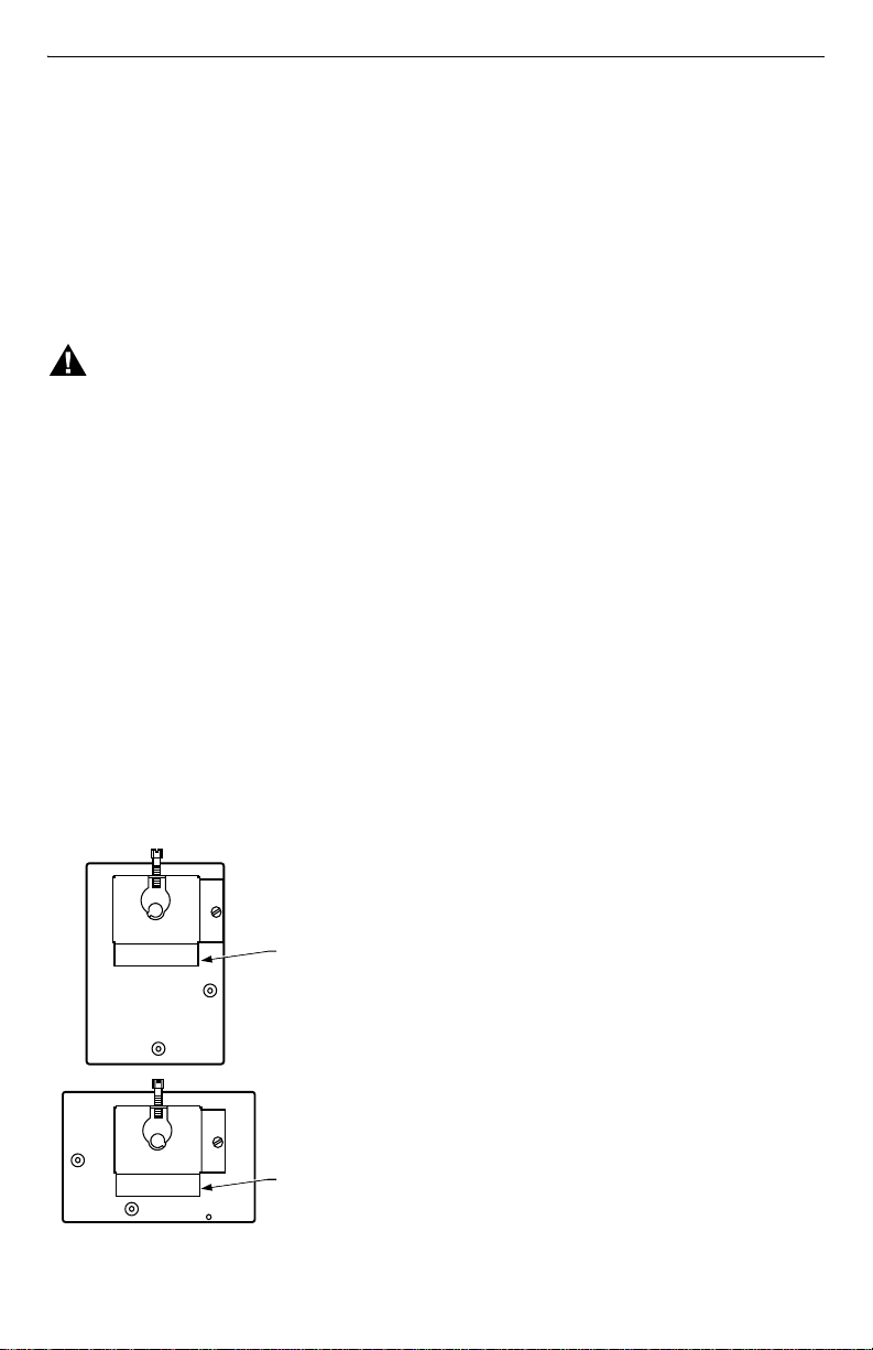
Mounting
The L7124U has a case that can be converted for either
horizontal or vertical mounting. See Fig. 1.
IMPORTANT
Immersion well must fit sensing element and
sensor bulb must rest against bottom of well.
New Installation
Order well assemblies for the L7124U separately; see
form 68-0040, Wells and Fittings for Temperature
Controllers. Boilers usually have tappings that allow
the well to be mounted horizontally so boiler water of
average temperature can circulate freely.
1. Turn off all power and drain the boiler.
2. If no tapping is provided, prepare properly sized
and threaded tapping near the top of the boiler.
3. Sparingly coat the well threads with pipe dope.
BRACKET POSITION FOR
VERTICAL MOUNTING
BRACKET POSITION FOR
HORIZONTAL MOUNTING
M8890
Fig. 1. Case designed for vertical
or horizontal mounting.
69-1232—2 2
NOTE: Do not attempt to tighten by using the case as a
handle.
4. Install the well in the boiler tapping and tighten
securely.
5. Refill boiler and check for water leakage.
6. Loosen but do not remove the clamp screw on the
L7124U case.
7. Insert the sensor element into the well until it
bottoms. (If necessary, slightly bend the tube inside
the case to hold the sensor against the bottom of
the well.)
NOTE: Some models have an adjustable wire length to
3 in. (76 mm). For these models, pull out extra
wire length from inside the case, if needed.
8. Fit the case into the well so the clamp on the case
slides over the flange on the well.
9. Securely tighten the clamp screw.
IMPORTANT
Best thermal response is obtained with a well
that snugly fits the sensor. Insert the sensor
until it rests against the bottom of the well. use
a well of correct length and bend the wiring, if
necessary, to hold the bulb against the bottom
of the well.
If the well is not a snug fit on the sensor, use
the heat-conductive compound (furnished with
TRADELINE models) as follows: Fold the
plastic bag of compound lengthwise and twist it
gently. Then snip off end of bag and work the
open end of the bag all the way into the well.
Slowly pull out the bag while squeezing it firmly
to distribute compound evenly in the well. Bend
the wiring, if necessary, to hold the sensor
against the bottom of the well and to hold outer
end of the sensor in firm contact with the side of
the well. See Fig. 2. Wipe excess compound
from the outer end of the well.
Replacement Installation
Turn off all power and remove the old control. Refer
to the cover insert of the old control to identify and tag
each external lead as it is disconnected. If the old well is
unsuitable for the new installation, remove it and proceed
with instructions for new installation. If the old well is
suitable, use it and an immersion well adapter (ordered
separately) for the installation. (The well clamp may fit
directly over the flange of the existing well spud and
using the adapter may not be necessary.) The adapter
has a flange at the wide end that fits into the well clamp
and is slotted lengthwise to accommodate the sensor
wire.
1. Loosen but do not remove the well clamp screw on
the side of the control case.
2. Pull out the wire until the sensor bottoms in the
well. Place adapter, if used, around the sensor wire
so it fits into the slot. See Fig. 2.
3. Make sure the wide end of the adapter fits into the
hole in the case. Position immersion well clamp
snugly over the flange of the adapter and tighten
the clamp screw.
4. Insert the sensor into the well as shown in Fig. 2.
(Distribute the heat-conductive compound in the
tube prior to bulb insertion.)
5. Securely tighten the setscrew against the adapter.
Page 3
L7124U UNIVERSAL OIL ELECTRONIC AQUASTAT® CONTROLLER
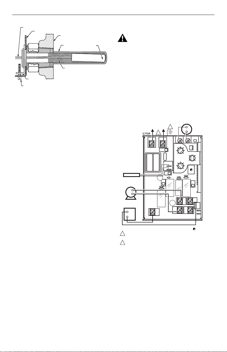
SENSOR WIRES
CONTROLLER CASE
IMMERSION
WELL CLAMP
IMMERSION WELL
CLAMP SCREW
BOILER
IMMERSION
WELL
HEAT-CONDUCTIVE COMPOUND
(OPTIONAL)
SENSOR
M16120
Fig. 2. Position of sensor in immersion well.
WIRING
WARNING
Electrical Shock Hazard.
Can cause serious injury or death.
Disconnect power supply before making wiring
connections to prevent electrical shock or
equipment damage.
All wiring must comply with local electrical codes and
ordinances. Do not exceed the specifications in the
Application section when wiring this control.
IMPORTANT
The terminals on these Aquastat® Controllers
are approved for use with copper wire only.
Follow the appropriate wiring diagrams shown on the
inside of the front cover of the L7124U or in Fig. 3 and 4.
LINE VOLTAGE
CIRCULATOR
SENSOR
L2
L1
(HOT)
L1
T1
1
PWR
SENSOR
2
1
C
ZC
2
F01
LOW VOLTAGE
THERMOSTAT
TL2T TSTAT
HIGH
LIMIT
DIFF.
LL
LOW
LIMIT
DSBL
B
ZC
LINE VOLTAGE OIL
BURNER RELAY
B2
1
POWER SUPPLY. PROVIDE DISCONNECT MEANS
AND OVERLOAD PROTECTION AS REQUIRED.
2
CONTROL CASE MUST BE CONNECTED TO EARTH
GROUND. USE GROUNDING SCREW PROVIDED.
C1
C2
ZR
LEGEND: = LED
B1
M17776
Fig. 3. L7124U single zone connections.
3 69-1232—2
Page 4

L7124U UNIVERSAL OIL ELECTRONIC AQUASTAT® CONTROLLER
R
TO ADDITIONAL R845A
L
B
SENSOR
LINE VOLTAGE
CIRCULATOR
INE VOLTAGE OIL
URNER RELAY
2
1
L1
PWR
T1
F01
SENSOR
2
1
C
ZC
B2
C2
LOW
VOLTAGE
THERMOSTAT
TL2T TSTAT
HIGH
LIMIT
DIFF.
LL
LOW
LIMIT
DSBL
B
ZC
C1
ZR
B1
RELAYS FOR OTHER ZONES
1
L1
(HOT) L2
LEGEND: = LED
1
POWER SUPPLY. PROVIDE DISCONNECT MEANS
AND OVERLOAD PROTECTION AS REQUIRED.
2
CONTROL CASE MUST BE CONNECTED TO EARTH
GROUND. USE GROUNDING SCREW PROVIDED.
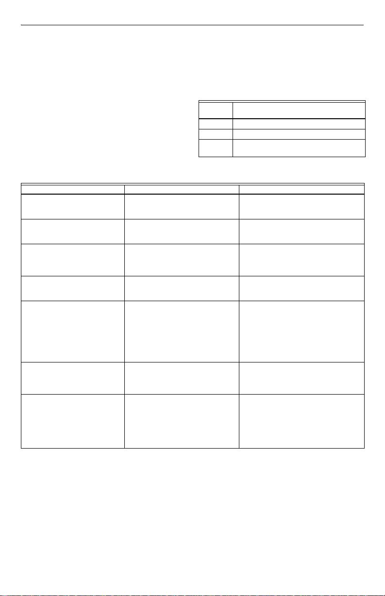
Fig. 4. L7124U multizone system with circulator connections.
R845A RELAY ZONE 2
6
5
3
4
1
2
ZONE 2
LOW VOLTAGE
THERMOSTAT
ZONE 2
CIRCULATO
M17777
69-1232—2 4
Page 5

OPERATION
).
L7124U UNIVERSAL OIL ELECTRONIC AQUASTAT® CONTROLLER
High Limit Controller
The high limit opens and turns off the burner when the
water temperature reaches the setpoint. The high limit
automatically resets after the water temperature drops
past the setpoint and through the 15°F (8°C) differential.
Low Limit and Circulator Controller
On a temperature rise, with the adjustable differential at
the minimum setting of 10°F (6°C), the burner circuit
breaks and the circulator circuit makes at the low limit
setpoint. On a temperature drop of 10°F (6°C) below the
low limit setpoint, the burner circuit makes and the
circulator circuit breaks. See Fig. 5.
CAUTION
Equipment Damage Hazard.
Can cause improper operation
1. Setting the Low Limit above the High Limit
disables the device.
2. Setting the Low Limit less than 15°F (8°C)
below the High Limit results in improper
circulator function.
SWITCH BREAKS ON
TEMPERATURE RISE.
HIGH LIMIT
SETTING
LOW LIMIT
SETTING
1
WHEN WATER REACHES LOW LIMIT SETTING, THE BURNER SHUTS
OFF OR THE CIRCULATOR PUMP STARTS (WHEN CALLING FOR HEAT
Fig. 5. Setpoints and differentials.
BURNER TURNS OFF.
CIRCULATOR OPERATES
ON A CALL FOR HEAT.
SWITCH MAKES ON
TEMPERATURE FALL.
BURNER OPERATES ON A
CALL FOR HEAT.
WITH NO HEATING
DEMAND, SWITCH BREAKS
ON TEMPERATURE RISE.
SWITCH MAKES ON
TEMPERATURE FALL,
BURNER IS ON TO
MAINTAIN MINIMUM
WATER TEMPERATURE.
CIRCULATOR IS OFF.
M21059
1
The L7124U can be in any of four operational states:
Normal, High-Limit, Low-Limit and Error. The controller
moves back and forth from High-Limit to Normal to
Low-Limit state as part of normal operation. However, the
controller enters only the Error state when there is an
abnormal condition such as an internal error or a bad
sensor. The operating states are:
1. Normal: Boiler temperature has gone below the
high limit setting (minus the fixed differential) and
has not exceeded the high limit setting; or, the
boiler temperature has gone above the low limit
setting and has not gone below the low limit setting
(minus the fixed differential).
2. High-Limit: Boiler temperature has gone above the
high limit setting and has not dropped below the
high limit setting (minus the fixed differential).
3. Low-Limit: Boiler temperature has gone below the
low limit setting (minus the low limit differential) and
has not gone above the low limit setting.
4. Error: The controller has detected an error
condition (e.g., open sensor) and has shut down
the burner output. The circulator and ZC output are
energized. The controller continues to function
and automatically restarts if the error condition
clears.
The operating sequence for the L7124U is shown in
Table 2.
CHECKOUT
Put the system into operation and observe operation
through at least one complete cycle to make sure that the
controller operates properly.
Table 2. L7124U Controller Operating Sequence.
Action System Response
Thermostat
calls for
heat.
Boiler
exceeds the
high limit.
Thermostat
is satisfied.
Error
condition.
Circulator starts when water temperature is
above low limit setting (if applicable).
Boiler temperature is checked.
Burner starts when water temperature is
below high limit setting and above low limit
setting.
Burner is turned off. Burner restarts when
the water temperature drops below the
high limit setting minus the differential.
Circulator and burner turn off.
When an error condition is detected, all
outputs except C and ZC are shut down.
Burner is off. Control continues to function
and restarts when error is corrected.
During the error check sequence, the
system checks for drift in the sensor and
corrosion in the connections.
5 69-1232—2
Page 6
L7124U UNIVERSAL OIL ELECTRONIC AQUASTAT® CONTROLLER
TROUBLESHOOTING
When attempting to diagnose system performance,
references to the LED can help to identify specific areas
not working properly. The LED are:
PWR—ON indicates 24 Vac power present.
C—ON indicates circulator relay energized.
TSTAT—ON indicates thermostat call for heat.
ZC—ON indicates power to zoning.
B—ON indicates burner relay energized.
LL/DSBL—
Table 4. Corrective Action .
System Condition Check Corrective Action
Boiler is cold, house is cold. PWR LED Off Check:
PWR LED On
TSTAT LED Off
PWR LED On
TSTAT LED On
B (burner) LED On
PWR LED On
TSTAT LED On
LL/DSBL LED Flashing
Boiler is hot, house is cold. PWR LED On
TSTAT LED On
C (circulator) LED On
PWR LED On
TSTAT LED On
C (circulator), ZC (zone circulator)
LED Off
PWR LED On
TSTAT LED On
ZC LED on
• ON indicates Low Limit function selected.
• OFF indicates Low Limit disabled.
• Flashing indicates error. See Table 3 and
Troubleshooting Guide, Table 4.
Table 3. LED Error Codes.
Number
of Blinks Cause
2 Sensor Error (Open or shorted sensor.)
3 System error(s); e.g., setpoint POT failure.
4 Safety relay has welded, device requires
.
replacement.
— 120 Vac system power.
— 1A fuse on L7124U.
Check:
— Thermostat
— Thermostat wiring
—Check:
—120 Vac B1-B2.
— If no, replace burner relay.
— If yes, check burner and wiring.
Refer to LED diagnostics, Table 3.
Check:
— 120 Vac, C1-C2.
— If no, replace circulator relay.
— Check for circulation, air entrap-
ment, water flow.
— If yes, check circulator and wiring.
— Check for circulation, air entrap-
ment, water flow.
Check:
— Boiler below low limit temperature,
wait for boiler to above low limit
temperature.
Check:
— Boiler above low limit.
— If yes, check for 120 Vac between
ZC and L2.
— If no, replace ZC relay .
— If yes, check switch relays, zone
circulators and wiring.
69-1232—2 6
Page 7

7 69-1232—2
Page 8

Home and Building Control Home and Building Control
Honeywell Honeywell Limited-Honeywell Limitée
1985 Douglas Drive North 35 Dynamic Drive
Golden Valley, MN 55422 Scarborough, Ontario
M1V 4Z9
69-1232—2 G.R. Rev. 12-01 www.honeywell.com
Printed in U.S.A. on recycled
paper containing at least 10%
post-consumer paper fibers.
 Loading...