

Page 1
L641
FEATURES
DESCRIPTION
SURFACE CONTACT
THERMOSTAT
PRODUCT DATA
• Versions available for use as a cylinder thermostat
in domestic hot water installations
• Versions available for use as a pipe thermostat in
fan-coil applications
• Version available for use as a pipe thermostat in
frost protection applications
• Version available for use as a pipe thermostat to
limit the supply water temperature in underfloor
heating and solid fuel systems
• The S.P.D.T. switching action is accomplished by a
snap-action MICRO SWITCH which is actuated by a
bimetal temperature sensing element
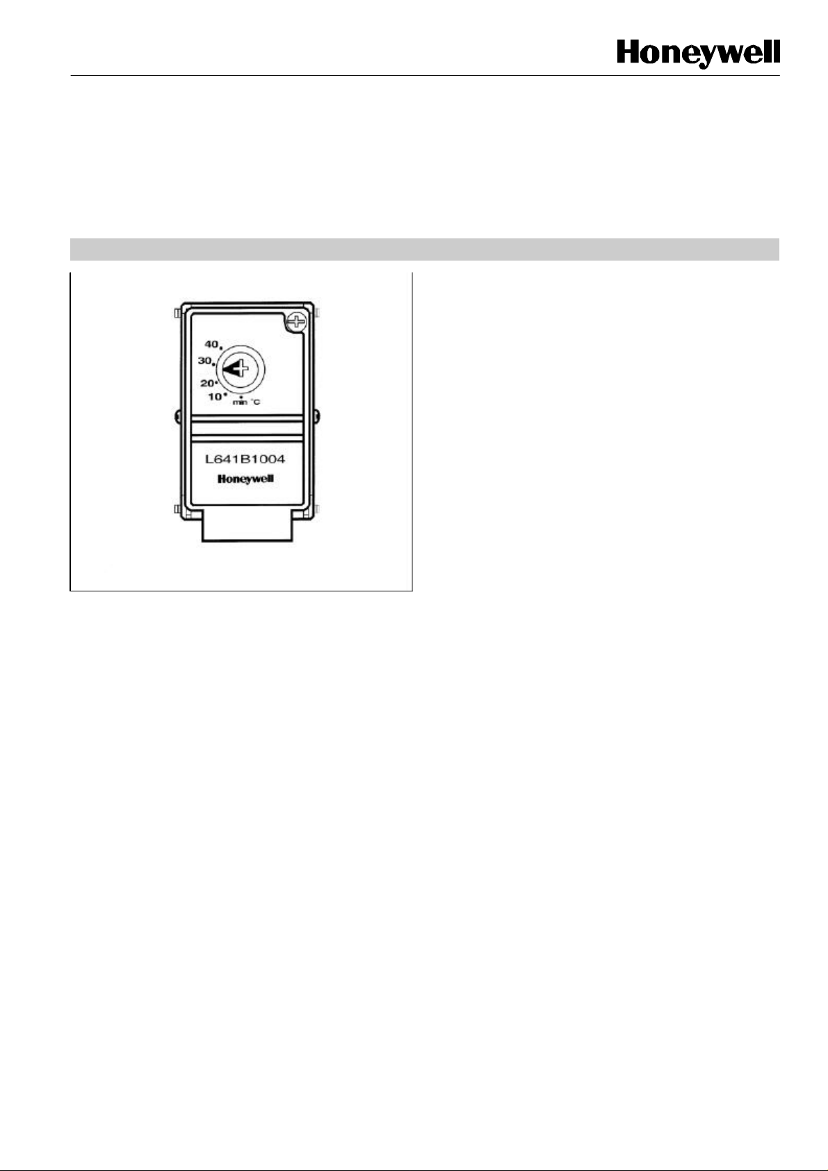
The L641 is a surface contact thermostat designed to sense
the water temperature in storage cylinders and water pipes,
and to provide temperature control, temperature limiting, and
temperature feedback functions.
L641A mounts directly onto domestic hot water cylinders and
can be wired to directly switch a wet central heating
circulating pump, or boiler, or to operate spring return and
motor open/motor close zone valves.
L641B mounts directly onto a pipe and can provide high limit,
low limit or frost protection in wet central heating systems or
automatic summer/winter changeover in XE70 and XE90 fancoil control systems.
• The desired temperature control point is set by the
clearly scaled temperature selector on the front
cover
• Wiring terminals are easily accessible
• Tamperproof temperature setting (L641B)
• Screwdriver slot temperature setting, with optional
manual setting knob supplied (L641A)
• Approvals - B.E.A.B. (meets EN 60730)
EN0R8444
Page 2
L641 SURFACE CONTACT THERMOSTAT
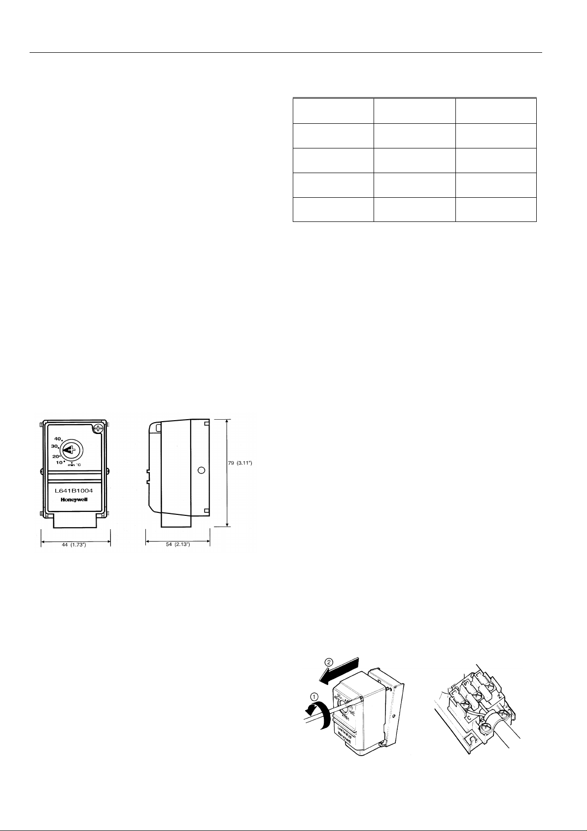
DIMENSIONS
SPECIFICATIONS
INSTALLATION
Dimensions in
millimetres (inches in brackets)
Supply
voltage
: 230 V~, 50...60 Hz
ORDERING SPECIFICATION
Switch action : S.P.D.T. Type 1CL
Switch rating : 4(2) A, 230 V~
Temperature
setting range
Differential : Approximately 10 K non-adjustable
Surface
temperature
range
Ambient
temperature
range
Mounting : L641A mounts directly onto cylinder
Dimensions : 44 x 79 x 54mm (1.73" x 3.11" x
Wiring : 3 terminals with wiring clamps,
: see table
: 0 to 95oC
: 0 to 70oC
using fixing strap provided
L641B mounts directly onto pipes
using fixing springs provided
2.13")
(w x h x d)
2
Model Application Temperature
Setting Range
L641Al039 Cylinder
Thermostat
L641Bl004 Low Limit Pipe
Thermostat
L641B1012 High Limit Pipe
Thermostat
L641Bl020 High Limit Pipe
Thermostat
Min, 40 to 80 o C
Min, 10 to 40o C
50 to 95oC
40 to 95oC
Mounting
The L641A cylinder thermostat should be mounted 1/4 to 1/
of the way from the bottom of the domestic hot water cylinder
after removing a section of the insulation and cleaning the
surface.
The L641B pipe thermostat should be positioned less than
0.6 m (2') from the boiler, or on a supply pipe to a fan-coil
unit, close to the 3-port control valve.
3
IMPORTANT
1. The installer must be a trained service
engineer
2. Disconnect the power supply before beginning
installation
Wiring
Cover removal Wiring to terminals
EN0R 8444 2
Page 3

L641 SURFACE CONTACT THERMOSTAT
APPLICATION
High Limit
Limit Control in Pipes
D.H.W. Storage Cylinders
Low Limit
L641A1039
L641Al039
L641Bl004
L641Bl012
L641Bl020
DHW Storage
Tanks/
Cylinders
(see note 1)
4
High Limit
Underfloor
Heating
Systems (see
note 2)
4 4
4 4
High Limit
Solid Fuel
Systems (see
note 2)
Low Limit
Frost
Protection
(see note 3)
4 4
Fan-Coil Unit
Summer/
Winter
Changeover
for 2-pipe
units (see
note 4)
Notes
1. The L641A should be mounted 1/4 to 1/3 of the way from the bottom of the cylinder.
2. The L641B should be mounted less than 0.6 m (2') from the boiler.
3. The L641B should be mounted on the boiler return pipe and used in conjunction with the T4360A FrostStat.
4. The L641B should be set to approx. 25o C and mounted on the supply pipe close to the 3-port control valve
such as to sense the water temperature even when the valve is closed.
Water Temperature Sensing and
and Tanks
For Underfloor Heating
For Solid Fuel Systems
For Frost Protection of
Exposed Pipework
T4360A FrostStat
3 EN0R 8444
Page 4

L641 SURFACE CONTACT THERMOSTAT
Note:
WIRING DIAGRAMS
L641A1039
L641B1012
L641B1004 Automatic
L641B1004
L641B1004 Automatic Summer/
Summer/Winter
Changeover for 2-pipe
DHWS ControL
Heating Load
Terminal 2 used on Honeywell
Y-Plan systems
Timer
Set to
25oC
L641B1020
High Limit
Heating Load and
existing controls
Contacts C and 1 break on
temperature rise
Set to
25oC
For wiring details
refer to the
appropriate XE70
or XE90 Product
Data sheet.
(ENOR8402, 8403,
8406)
Summer/Winter Changeover
Low Limit
(Frost
Winter Changeover XE70 series
Typical wiring
Protection)
XE70 Series
Connected to override existing
time and temperature controls
Contacts C and 1 make on
temperature fall
Fan coil
Unit
Honeywell Control Systems Limited Helping You Control Your World
Newhouse Industrial Estate
Motherwell ML1 5SB
United Kingdom
EN0R 8444
 Loading...