

Page 1
L6008A Remote Bulb Aquastat® Controller
Installation Instructions for the Trained Service Technician.
Application
This remote bulb, immersion-type controller operates in
response to temperature changes in hydronic heating systems and in other heated liquids. It provides spdt switching
for three wire circuit applications, combining low limit and
circulator control.
Switch ratings are shown on the inside cover. The
electrical requirements of controlled equipment must not
exceed these ratings.
The R to B contacts make to start the boiler when the
boiler water temperature drops to the dial setting less the
differential. The R to W contact breaks to prevent circulator
operation. When the boiler water temperature rises to the
dial setting, R to B breaks and R to W makes. See Fig. 1.
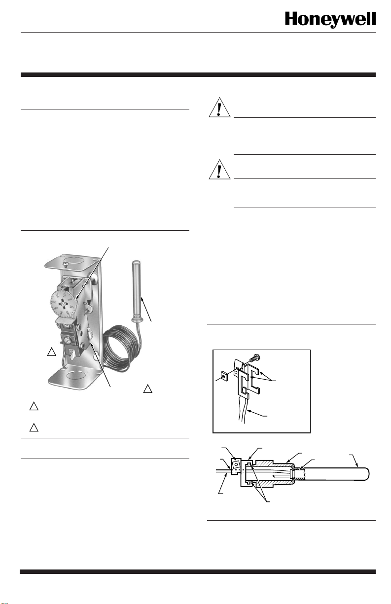
Fig. 1—Internal view of L6008A.
2
1
ONLY MODELS WITH ADJUSTABLE DIFFERENTIAL HAVE
ADJUSTMENT WHEEL. STANDARD MODELS ARE FIXED AT
APPROXIMATELY 5
SELECT MODELS HAVE SCREW TERMINAL, NOT TAB
2
TERMINAL.
o
F (3o C).
SETPOINT
INDICATING
DIAL
DIFFERENTIAL
ADJUSTMENT
WHEEL
IMMERSION
BULB
1
M8814
Installation
WHEN INSTALLING THIS PRODUCT…
1. Read these instructions carefully. Failure to follow
them could damage the product or cause a hazardous condition.
2. Check the ratings given in the instructions and on the
product to make sure the product is suitable for your application.
3. Installer must be a trained, experienced service technician.
4. After installation is complete, check out product operation as provided in these instructions.
WARNING
CAN CAUSE PROPERTY DAMAGE,
SEVERE INJURY OR DEATH.
This product is intended for use only in systems
with a pressure relief valve.
CAUTION
Disconnect the power supply before beginning
installation to prevent electrical shock or equipment damage.
The installation should be done only by a qualified ser-
vice person.
The remote temperature-sensing bulb can either be installed in an immersion well that extends into the boiler or
tank, or it can be directly immersed in the liquid. See Fig. 2.
For installations not using a well, secure the remote bulb with
a compression fitting or boiler fitting. See Fig. 3 and 4.
Order well, compression fitting, or boiler fitting separately. Sizes available: 1/2-in., 3/4-in. N. P. T. spud. Well, if
used, must snugly fit sensing bulb for good thermal response.
Insert bulb until it rests against bottom of well, then hold it
there while tightening the tubing clamp.
Fig. 2—Immersion well mounting.
JAWS
SPREAD JAWS
TO FIT OVER
RIDGE ON SPUD
OF WELL
SCREWDRIVER
INSERT— MOUNTING CLAMP
DRAW
NUT
B
TUBING
MOUNTING
CLAMP
A
SPUD
BULB
WELL
M8777
J.H. • Rev. 1-95 • ©Honeywell Inc. 1995 • Form Number 95-5880—1
Page 2
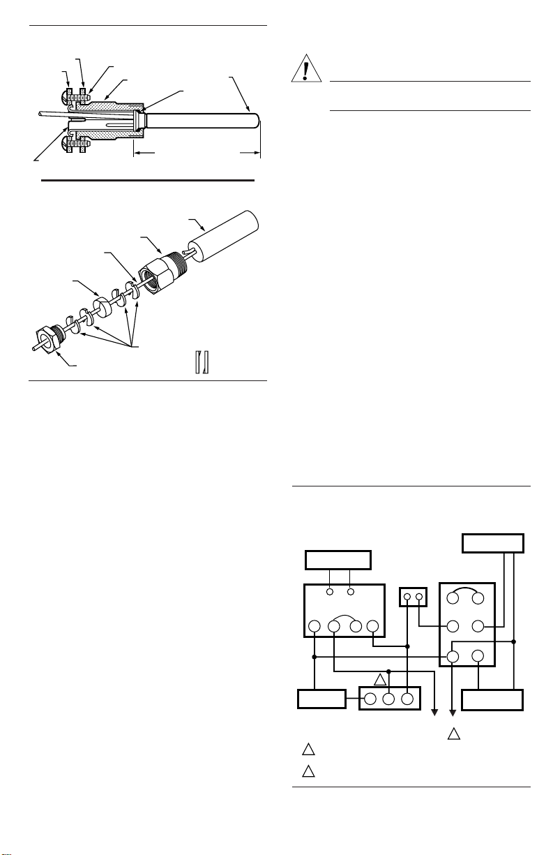
Fig. 3—Mounting with compression fitting.
CLAMP B
CLAMP A
SPLIT SLEEVE
CLAMP SCREWS (2)
BULB
COMPRESSION
FITTING
INSERTION LENGTH
APPROX. 3-3/16 in. (81 mm)
SEALING
WASHER
BULB
M8815
Fig. 4—Mounting with boiler fitting.
IMMERSION
BULB
BOILER PLUG
CAPILLARY TUBING
COMPOSITION DISK
(SLOTTED)
EXAMPLE OF SLOTTED WASHERS
ASSEMBLED
PACKING NUT
IN PAIRS:
M8816
The boiler manufacturer usually provides a tapping for
inserting the Aquastat® Controller sensing element. Locate
this tapping in a representative point where typical water
temperature can be measured. Do not locate the bulb or
protecting immersion well close to a hot or cold water inlet or
a steam coil.
If the system is filled, drain the system to a point below the
boiler tapping, or wherever the sensing bulb is to be installed.
Install the bulb in the supply line of an indirect water
heater, in the direct water heater itself, or in the feed riser,
about 6 in. above the boiler. If the riser is valved, the bulb can
be installed between the boiler and the valve.
TO MOUNT THE CASE
1. Remove the cover and fasten the case to the wall or
panel, using the three mounting holes in the back of the case.
2. If desirable, reroute tubing to run through any of the
other three corner notches in the case. Be careful not to bend
tubing sharply or kink it. Bends should be at least one in.
radius.
TO INSTALL REMOTE BULB
Immersion Well Mounting
1. Screw the well into the boiler, tank, or pipe tapping.
2. Insert bulb into the well, pushing tubing until the bulb
bottoms in the well.
3. Attach a retainer clamp to the end of the well spud.
Loosen the draw nut and spread the jaws of the clamp with a
screwdriver if necessary.
4. With the retainer clamp attached to the well spud (be
sure jaws of clamp hook over ridge at end of spud, as shown
at points A), adjust tubing to fit through retainer clamp
groove, as shown at point B.
5. Tighten draw nut so that retainer clamp is firmly
attached to well spud and tubing is held securely in place.
CAUTION
Do not secure draw nut so tightly that retainer
clamp could collapse tubing.
MOUNTING WITH COMPRESSION FITTING
l. Screw the fitting into the boiler or pipe tapping.
2. Slide the sealing washer onto the bulb.
3. Insert the bulb into the boiler fitting until the bulb
bottoms.
4. Slide the split sleeve into the fitting.
5. Place the clamps A and B on the assembly so that the
sleeve is drawn into the fitting when the screws are tightened.
NOTE: Be sure that the nub on clamp A engages space
between the sleeve and the clamp.
6. Tighten clamp screws evenly.
MOUNTING WITH BOILER FITTING
l. Screw the fitting into the boiler or pipe tapping.
2. Place the packing nut on the tubing.
3. Slide the bulb completely through the fitting.
4. Place the composition disk and four slotted brass
washers on the tubing in the order shown in Fig. 4. Turn brass
washers so that the slots are 180 degrees to each other.
5. Slide the seal assembly into the fitting and tighten the
packing nut.
WIRING
Be sure all wiring agrees with applicable codes, ordinances, and regulations for wire size, type of insulation, and
enclosure. The controllers are provided with conduit knockouts in the top and bottom of case.
Refer to Fig. 5 for a typical connection diagram.
Fig. 5—Typical connection diagram for an oil-
fired hydronic heating system that provides
year around domestic hot water.
BURNER MOTOR
24V THERMOSTAT
RA89A RELAY
2
1 3
CIRCULATOR
POWER SUPPLY. PROVIDE DISCONNECT MEANS AND
1
OVERLOAD PROTECTION AS REQUIRED.
SELECT MODELS HAVE 1/4 IN. TAB TERMINAL FOR W
2
TERMINAL.
L4008A OR E
HIGH LIMIT
CONTROLLER
4
2
W
B
L6008A
CIRCULATOR
LOW LIMIT
CONTROLLER
R
RA817A
PROTECTORELAY™
CONTROL
T
1
2
IGNITION
TRANSFORMER
L1
L2
(HOT)
1
T
3
4
M8785
95-5880—1 2
Page 3

Adjustments
Checkout
Set the differential to correspond with the boiler
manufacturer recommendations. To adjust models with adjustable differential, rotate the wheel on the back of the snap
switch until the desired reading is aligned with the V notch in
the frame. The wheel provides an adjustment from 5 to 30
degrees (F). Replace the cover on the Aquastat® Controller.
Adjust the control point to correspond with the boiler
manufacturer’s recommendations. To adjust, insert a screwdriver in the slotted screw-type head located beneath the
window in the cover. Turn the scale to the desired control
point.
Check to make certain that the Aquastat® Controller is
installed and adjusted properly.Operate the system and observe the action of the device through several cycles to make
certain that it provides proper low limit cut-out protection
and circulator control. Make any further adjustments needed.
3 95-5880—1
Page 4

Home and Building Control Home and Building Control Helping You Control Your World
Honeywell Inc. Honeywell Limited—Honeywell Limitée
1985 Douglas Drive North 740 Ellesmere Road
Golden Valley, MN 55422 Scarborough, Ontario
M1P 2V9
Printed in Mexico
QUALITY IS KEY
 Loading...