

Page 1
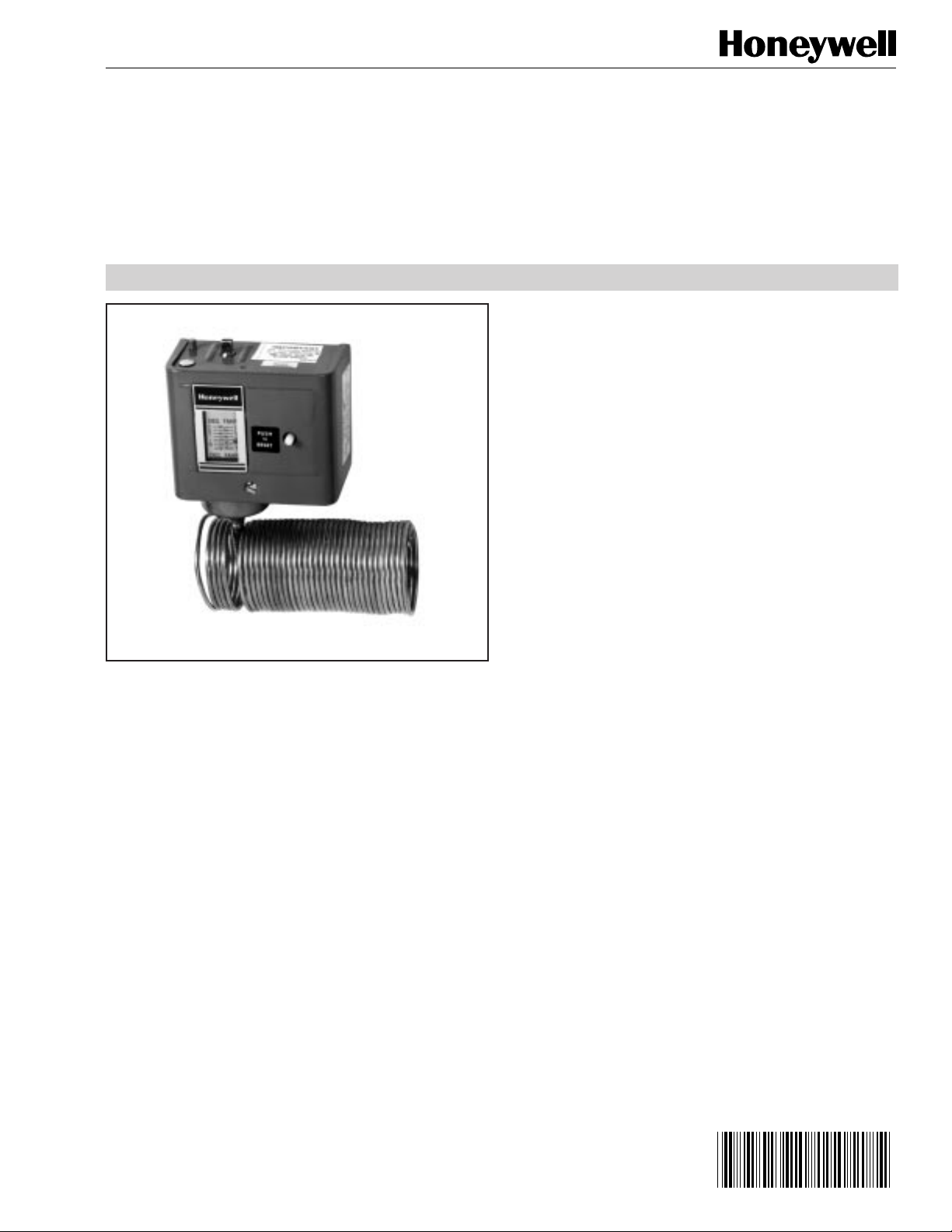
L482A Low Limit
Controller
SPECIFICATION DATA
FEATURES
• Mounts horizontally or vertically on a wall or panel, or
directly on sheet metal duct
• Manual reset
• Two spst switches
RC38
GENERAL
The L482A Low Limit Controller provides temperature or limit
control of air conditioning systems by operating electric
motors for dampers, valves, compressors, or fans. It
responds to the lowest temperature to which any one-foot
portion of the 20-foot, temperature-sensitive element is
exposed. It can be used to close electrically operated
dampers, open electrically operated valves or to shut off
compressor or fan motors when the element senses
temperatures below a critical point. The L482A can also act
as a frost alarm sensor in storehouses or other locations
where low temperatures would damage building contents.
DESCRIPTION
The L482A Low Limit Controller provides temperature or limit
control of air conditioning systems by operating electric
motors for dampers, valves, compressors, or fans.
Copyright © 1986 Honeywell Inc. • All Rights Reserved
74-3935
Page 2
L482A LOW LIMIT CONTROLLER
SPECIFICATIONS
Model:
❑ L482A Low Limit Controller with two spst snap switches
Switching Action:
Main switch (M2) opens on a drop to setpoint; auxiliary switch
(M1) closes. Manually reset.
Temperature Setpoint Range:
15 to 55F (-9 to 13C), stop limits minimum to 34F (2C)
Sensing Means:
20 ft (6.1m) sensing element. Controller operates at coldest
one-foot portion of element.
Temperature Setting Means:
Slotted screw at top of device. Setpoint is indicated through
scale opening in cover.
Differential:
Nonadjustable and additive; 5F (3K)
Listing:
UL Listed
CSA Listed
Electrical Ratings (Amperes):
Pilot Duty Rating (Both Poles):
125 VA, 24 to 600V ac; 57.5 VA, 120 to 300V dc
Switch Number M2 (Main)
Voltage 120Vac208Vac240Vac277V
ac
Full Load 16.0 9.2 8.0 —
Locked Rotor 96.0 55.2 48.0 —
Non-inductive 16.0 9.2 8.0 7.2
Switch Number M1 (Auxiliary)
Full Load 6.0 3.3 3.0 —
Locked Rotor 36.0 19.8 18.0 —
Non-inductive 6.0 6.0 6.0 6.0
Accessories:
Bag assemblies for immersing sensing element in water coil
(includes 1/2-14 NPT plug):
7617M 3/4 in. (19 mm) long opening for sensing element
7617ABY 1-3/8 in. (35 mm) long opening for sensing
element
CCT1802 Grommet for mounting element in hole in duct wall
CCT2600 Clips for mounting element inside duct
7640HX Kit for installing sensing element when access
into duct is not possible
Ambient T emperatures:
Case:
Maximum: 140F (60C)
Minimum: 20F (-7C) or more above setpoint
Element:
Maximum: 250F (121C)
Finish:
Gray enamel
Mounting Means:
Mounting holes under cover
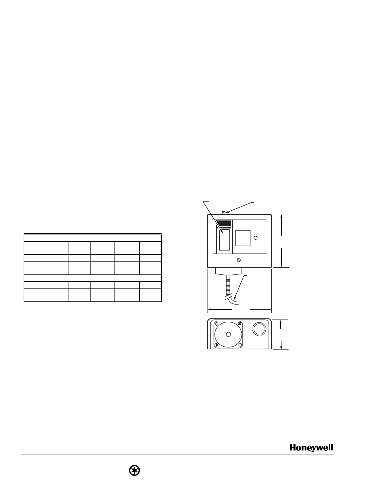
Dimensions In Inches (Millimeters):
SETPOINT
SCALE
PUSH
RESET
TO
1/8 INCH
BY 20 FT
SENSING
ELEMENT
SETPOINT
ADJUSTMENT
4-11/16
(119)
By using this Honeywell literature, you agree that Honeywell will have no
liability for any damages arising out of your use or modification to, the
literature. You will defend and indemnify Honeywell, its affiliates and
subsidiaries, from and against any liability, cost, or damages, including
attorneys’ fees, arising out of, or resulting from, any modification to the
literature by you.
Home and Building Control
Honeywell Inc.
Honeywell Plaza
P.O. Box 524
Minneapolis MN 55408-0524
Honeywell Latin American Division
Miami Lakes Headquarters
14505 Commerce Way Suite 500
Home and Building Control
Honeywell Limited-Honeywell Limitée
740 Ellesmere Road
Scarborough Ontario
M1P 2V9
Honeywell Europe S.A.
3 Avenue du Bourget
B-1140 Brussels Belgium
Miami Lakes FL 33016
74-3935 10-86
74-3935
Printed in U.S.A. on recycled paper
containing at least 10% post-consumer paper fibers
2
3-63/64
(101)
2-3/32
(53)
C277
Honeywell Asia Pacific Inc.
Room 3213-3225
Sun Hung kai Centre
No. 30 Harbour Road
Wanchai
Hong Kong
Helping You Control Your World
 Loading...