

Page 1
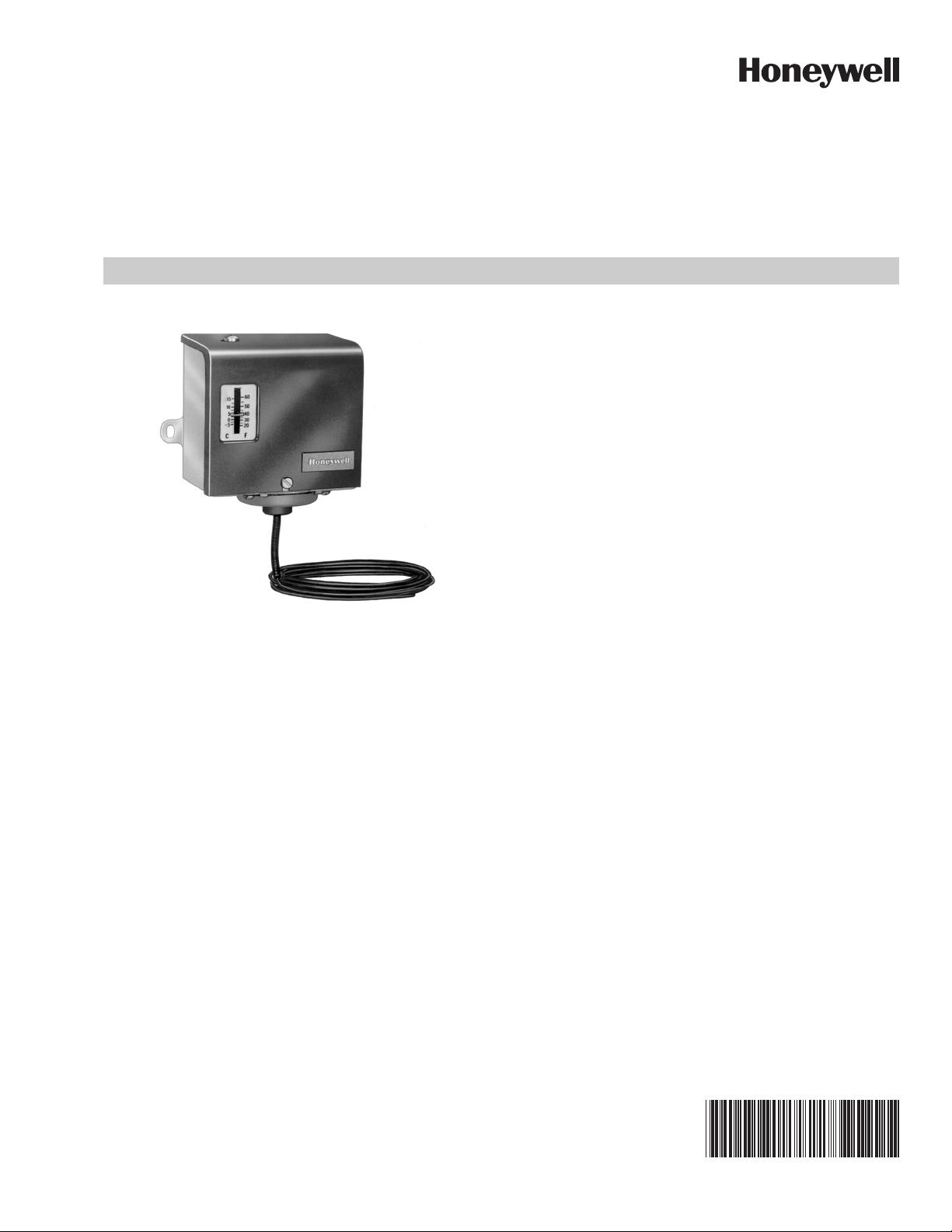
L480B,G Temperature Controllers
PRODUCT DATA
FEATURES
• Typical applications include freezer cabinets, display
cases, beverage coolers, milk cooling tanks and air
conditioners.
• The L480B can act as a frost alarm operator in
storehouses, orchards, or other locations where frost
could damage crops or equipment.
• The L480B automatically recycles. It has a single-pole,
double-throw (spdt) switch that can be wired to make
an alarm circuit at the setpoint.
• The L480G is a manual reset model. Its single-pole,
single-throw (spst) switch locks out the control circuit
on temperature fall to the setpoint.
• A dual temperature scaleplate is provided for both
Fahrenheit and Celsius readings.
• The temperature range is 20°F to 60°F (-5°C to +15°C).
• The L480B,G has a 20 foot (6 meter) sensing element
APPLICATION
The L480B,G Temperature Controllers operate electric
dampers, valves, and compressor or fan motors to provide
temperature or limit control of air conditioning systems and
refrigeration units.
with no sensing bulb.
• The enclosed snap switch is dustproof and
moistureproof for trouble-free operation.
• The controller can be mounted horizontally or
vertically on a wall or panel, or directly on the
compressor case.
Contents
Application ........................................................................ 1
Features ........................................................................... 1
Specifications ................................................................... 2
Ordering Information ........................................................ 2
Installation ........................................................................ 2
Operation and Checkout ................................................... 4
60-2203-05
Page 2
L480B,G TEMPERATURE CONTROLLERS
CAUTION
SPECIFICATIONS
Models:
L480B Temperature Controller with spdt snap switch, auto-
matic recycling.
L480G Temperature Controller with spst snap switch, manual
reset.
Switching Action:
L480B: Breaks control circuit and makes another circuit
(makes R-B and breaks R-W) on temperature fall.
Automatically recycles.
L480G: Breaks control circuit on temperature fall. Manual
reset.
Electrical Ratings (Amperes):
See Table 1.
DC Rating: 0.2A at 120 Vdc, 0.1A at 240 Vdc.
Pilot Duty Rating: 125 VA
Table 1. Full Load and Locked Rotor Ampere ratings.
L480B,G 120 Vac 240 Vac
Full Load 10.2 6.5
Locked Rotor 61.2 39.0
Ambient Temperature Range:
-20°F to +125°F (-11°C to +52°C).
Maximum Sensor Temperature:
225°F (107°C).
Operating Temperature Range:
20°F to 60°F (-5°C to +15°C); Dual Fahrenheit/Celsius
scaleplate.
Temperature Sensing Means:
20 ft (6m) element, no sensing bulb.
Temperature Setting Means:
A slotted screw at the top of the controller. The setpoint is
indicated through a scale opening in the cover.
Differential:
Nonadjustable, additive, and fixed, 10°F (6°C) maximum.
Finish:
Gray.
Mounting Means:
Mounting lugs located on back of case.
Dimensions:
See Fig. 1.
Approvals:
Underwriters Laboratories Inc., Listed: File Number
SA481, Vol. No. 2, dated 02-09-66; Guide No. SDFY2.
Canadian Standards Association Certified: Listing G, File
No. LR1620; Guide No. 400-E-0.
Accessories:
314439 Clips for mounting element inside duct. Specify
quantity needed when ordering.
7640HX Assembly Kit for installing tubing when access
into duct is not possible.
For Immersion well assemblies, see Honeywell
TRADELINE® Catalog.
113665 Grommet.
INSTALLATION
When Installing this Product...
1. Read these instructions carefully. Failure to follow them
could damage the product or cause a hazardous condition.
2. Check the ratings given in the instructions and on the
product to make sure the product is suitable for your
application.
3. Installer must be a trained, experienced service technician.
4. After installation, check out the product as provided in
these instructions.
Disconnect the power supply before installation to
prevent electrical shock or possible equipment
damage.
ORDERING INFORMATION
When purchasing replacement and modernization products from your TRADELINE® wholesaler or distributor, refer to the
TRADELINE® Catalog or price sheets for complete ordering number. If you have additional questions, need further information,
or would like to comment on our products or services, please write or phone:
1. Your local Honeywell Environmental and Combustion Controls Sales Office (check white pages of your phone directory).
2. Honeywell Customer Care
1885 Douglas Drive North
Minneapolis, Minnesota 55422-4386
3. http://customer.honeywell.com or http://customer.honeywell.ca
International Sales and Service Offices in all principal cities of the world. Manufacturing in Belgium, Canada, China, Czech
Republic, Germany, Hungary, Italy, Mexico, Netherlands, United Kingdom, and United States.
60-2203—05 2
Page 3

L480B,G TEMPERATURE CONTROLLERS
CAUTION
CAUTION
7/8 (22) DIAMETER HOLE
FOR 1/2 INCH CONDUIT
CONNECTION
MANUAL RESET
MODEL ONLY
2-9/16 (65)
(MANUAL
RESET
MODEL
ONLY)
1-1/16
(27) (2)
1-1/16
(27)
3-5/16
(84)
3/16
(5) (2)
5/16
(8) (2)
3-5/16 (84)
3-11/16 (94)
2-5/16 (59)
2-9/32
(58)
M11026A
Fig. 1. L480 Temperature Controller dimensions in in. (mm).
Location
Locate the sensing element where it can sense the average
temperature of the space or liquid to be controlled. The
L480B,G case must be located where the ambient temperature
is at least 20°F (11°C) above the scale range setpoint. Do not
locate the element near a hot or cold inlet.
NOTE: The L480B,G case and excess element must be
located where ambient temperature is always at
least 20°F (11°C) above the setpoint of the controlled medium. For settings above the midpoint
of the temperature range, it may be necessary to
locate the controller case close to a steam pipe or
other warmsurface and to be sure the element
does not extend across a cold surface.
Mounting
Fasten the controller to a rigid vertical or horizontal surface
through the holes in the two mounting lugs projecting from
either side of the controller case.
Do not uncoil more element or capillary than is
required for the application. Do not sharply bend
the element or capillary or more than necessary—
bending hardens the element and makes it brittle.
Bends must have at least a one in. (25 mm) radius.
Do not make bends close to the control or pull on
the element or capillary. If the element or capillary
can be subjected to vibration, protect any surface
that makes contact.
Mounting the Element
Strap the element on a coil; for example, in an area where
freezing can occur, or mounted in a duct. Use as much of the
element as necessary for maximum protection.
Use metal straps to fasten the element to the coil to be
controlled.
Use clips (available as listed in Accessories section) for
mounting the element in a duct. See Fig. 2.
WIRING
To prevent possible electrical shock or equipment
damage, disconnect power supply before wiring
the L480B,G Temperature Controller.
All wiring must be in compliance with local codes and ordinances. Refer to installation and wiring information supplied
with the equipment to be controlled and to Fig. 3 and 4.
IMPORTANT
L480B,G Temperature Controllers are approved for
use with copper wire only
3 60-2203—05
Page 4

L480B,G TEMPERATURE CONTROLLERS
DUCT
WALL
CAPILLARY
TUBING
113665
GROMMET
AVERAGING
ELEMENT
USE NO. 10
SHEETMETAL
SCREWS
314439
CLIP
BEND HERE
IF NECESSARY
M11027
L1 (HOT)
ALARM
CONTROLLED
EQUIPMENT
L2
L480B
POWER SUPPLY. PROVIDE DISCONNECT MEANS AND OVERLOAD
PROTECTION AS REQUIRED.
SWITCH MAKES R-B, BREAKS R-W ON TEMPERATURE
FALL TO SETPOINT.
1
1
2
2
R
B
W
M11039
L1 (HOT)
CONTROLLED
EQUIPMENT
L2
L480G
POWER SUPPLY. PROVIDE DISCONNECT MEANS AND OVERLOAD
PROTECTION AS REQUIRED.
SWITCH BREAKS ON TEMPERATURE FALL TO SETPOINT.
MUST BE MANUALLY RESET.
1
1
2
2
M11040
OPERATION AND CHECKOUT
Operation
The L480B Temperature Controller has an spdt switch and
automatically recycles. It breaks the control circuit and makes
another circuit (makes R-B and breaks R-W) on temperature
fall.
Fig. 2. Use 314439 Clips to mount L480B,G Temperature
Controller element in duct.
Fig. 3. Typical hookup for L480B Temperature Controller
with alarm circuit.
Fig. 4. Typical hookup for L480G Temperature Controller.
The L480G Temperature Controller has an spst. It breaks the
control circuit on temperature fall and must be manually reset
to resume operation.
Temperature Setting
Turn the temperature adjustment screw (located on the top of
the L480 case) to move the indicator on the front of the case
to the desired cutoff point. The L480 has a fixed, additive
differential of 10°F (6°C) above the control setpoint.
NOTE: Slight changes in temperature setting can be
required to correct for altitude changes. The
operating point drops approximately 1°F (0.6°C)
per 1000 ft (305m) above sea level.
Checkout
With the system operating, increase the temperature setting
until the switch operates. Cooling equipment should turn off
and the alarm circuit (if used) should be energized.
Decrease the temperature setting. The alarm should
deenergize, and the equipment should return to normal
operation.
By using this Honeywell literature, you agree that Honeywell will have no liability for any damages arising out of your use or modification to,
the literature. You will defend and indemnify Honeywell, its affiliates and subsidiaries, from and against any liability, cost, or damages,
including attorneys’ fees, arising out of, or resulting from, any modification to the literature by you.
Automation and Control Solutions
Honeywell International Inc.
1985 Douglas Drive North
Golden Valley, MN 55422
customer.honeywell.com
On manual reset models, reset the red plunger to resume
normal operation.
® U.S. Registered Trademark
© 2014 Honeywell International Inc.
60-2203—05 M.S. Rev. 04-14
Printed in United States
 Loading...