

Page 1
APPLICATION
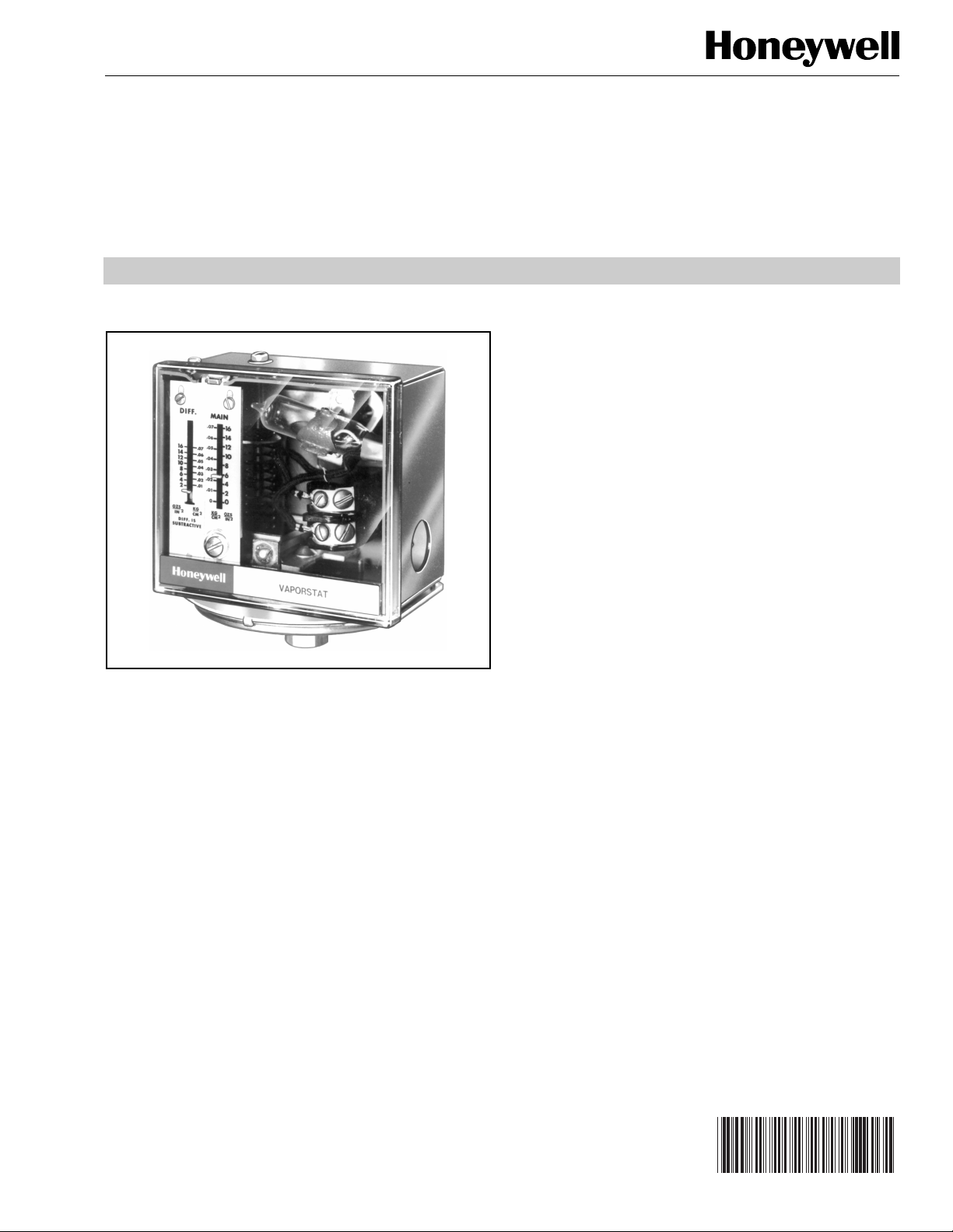
The L408A,B and L608A VaporStat® Controllers are line
voltage pressure controllers that provide operating control or
automatic limit protection for pressure systems of up to 4 psi
(0.28 kg/cm2 or 27.6 kPa).
L408A,B; L608A
VaporStat® Controllers
PRODUCT DATA
FEATURES
• Primarily for use in vapor heating systems, but also
may be used with liquids, air, and other
noncombustible gases
• Stainless steel diaphragm also allows use with
ammonia, oxygen, distilled water, and similar media.
• L408A and B models have an spst switch; L408A
breaks and L408B makes when pressure rises to the
main scale setpoint.
• L608A models have an spdt switch that breaks R-B
when pressure rises to the main scale setpoint.
• Dustproof, trouble-free mercury switch.
• Maximum surge pressure of 15 psi (103.4 kPa).
• All models have an adjustable subtractive differential.
• Adjustments are made by screws on top of case.
• Scaleplates are marked in English (psi) and metric
• Case has clear plastic cover so that pressure settings
• Leveling indicator visible through cover.
• Hexagonal fitting with 1/4-18 NPT internal threads for
• Can also be surface mounted by screws through holes
2
(kg/cm
and switch action can be observed.
direct mounting to the 14026 Steam Trap (siphon loop),
which is included.
(knockouts) in back of case.
) units.
® U.S. Registered Trademark
Copyright © 2003 Honeywell International Inc.
All Rights Reserved
Contents
Application ........................................................................ 1
Features ........................................................................... 1
Specifications ................................................................... 2
Ordering Information ........................................................ 2
Installation ........................................................................ 3
Wiring ............................................................................... 5
Setting and Checkout ....................................................... 6
Service Information .......................................................... 7
60-2158-5
Page 2
L408A,B; L608A VAPORSTAT® CONTROLLERS
SPECIFICATIONS
IMPORTANT
The specifications given in this publication do not
include normal manufacturing tolerances. Therefore,
this unit may not match the listed specifications
exactly. Also, this product is tested and calibrated
under closely controlled conditions, and some minor
differences in performance can be expected if those
conditions are changed.
Models:
L408A,B and L608A VaporStat® Controllers. See Tables 1, 2,
and 3 below. All models include a 14026 Steam Trap
(siphon loop), which is necessary for boiler installations.
Table 3. Operating Ranges Available for All Models.
Pressure Ranges Midscale Subtractive Differential (Adjustable)
English Units kg/cm
0 to 16 oz/in.
0 to 4 psi 0 to 0.28 0 to 27.6 4 to 16 0.02 to 0.07 1.7 to 6.9
0 to 16 oz/in.
2
2
0 to.0.07 0 to 6.9 2 to 16 0.01 to 0.07 0.9 to 6.9
0 to 0.7 0 to 6.9 3.5 to 16 0.02 to 0.07 1.6 to 6.9
2
kPa oz/in.
Model Switch Type
L408A Spst Breaks
L408B Spst Makes
L608A Spdt Breaks R-B; makes
Table 2. Switch Contact Ratings (in amperes at 50/60 Hz).
Model Load
L408A,B Full Load 8.0 5.1 2.4 1.2
L608A Full Load 8.0 5.1 2.0 1.0
Table 1. Models Available.
Switch Action on
Pressure Rise
R-W.
120
240
Vac
Vac
Locked Rotor 48.0 30.6 24.0 12.0
Noninductive 10.0 5.0 5.0 2.0
Locked Rotor 48.0 30.6 20.0 10.0
Noninductive 10.0 5.0 8.0 4.0
2
kg/cm
2
120
Vdc
kPa
240
Vdc
Maximum Surge Pressure:
15 psi (1.05 kg/cm
Switch:
Mercury switch in all models.
Pressure Sensing Element:
Stainless steel diaphragm.
Maximum Ambient Temperature:
150°F (66°C).
2
or 103.4 kPa).
Minimum Ambient Temperature:
-35°F (-37°C); also refer to note under Location and Mounting
in the Installation section.
Adjustment Means:
Screws on top of controller case. Scales are marked in psi
and kg/cm
Electrical Connections:
Internal screw terminals; holes in side of case for 1/2 inch
conduit.
2
.
ORDERING INFORMATION
When purchasing replacement and modernization products from your TRADELINE® wholesaler or distributor, refer to the
TRADELINE® Catalog or price sheets for complete ordering number.
If you have additional questions, need further information, or would like to comment on our products or services, please write or
phone:
1. Your local Honeywell Automation and Control Products Sales Office (check white pages of your phone directory).
2. Honeywell Customer Care
1885 Douglas Drive North
Minneapolis, Minnesota 55422-4386
In Canada—Honeywell Limited/Honeywell Limitée, 35 Dynamic Drive, Scarborough, Ontario M1V 4Z9.
International Sales and Service Offices in all principal cities of the world. Manufacturing in Australia, Canada, Finland, France,
Germany, Japan, Mexico, Netherlands, Spain, Taiwan, United Kingdom, U.S.A.
60-2158—5 2
Page 3
L408A,B; L608A VAPORSTAT® CONTROLLERS
)
M19770
Mounting Means:
Hexagonal fitting on diaphragm has 1/4-18 NPT internal
threads for mounting on a pipe or steam trap (siphon loop).
Also can be surface mounted by screws through two holes
(knockouts) in back of case.
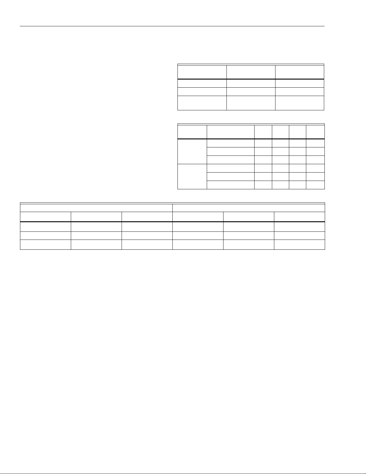
Dimensions:
See Fig. 1; also Fig. 2 for mounting steam trap (siphon loop).
Weight:
2 lb, 4 oz. (1.02 kg).
Finish:
Gray.
Approvals:
Underwriters Laboratories Inc. Listed: File No. MP466, Vol.
10; Guide No. MBPR.
Canadian Standards Association Certified: File No. LR1620;
Guide No. 400-E-0.
Replacement Parts:
129178 Thermoplastic Cover.
4-1/2 (114)
COVER
4-11/32 (110)
CASE
1-61/64
(50)
1-5/32
(29)
1-15/16
(49)
14026 Steam Trap (siphon loop)—1/4 inch black iron pipe;
included with all models.
Accessories:
33312B Knurled Adjustment Knob—with setscrew; fits on
main scale pressure adjusting screw.
4074BWJ Limit Stop Assembly—to limit setpoint ranges:
includes 129564 Range Stop, 107194 Range Stop Screw,
and 23466 Wrench.
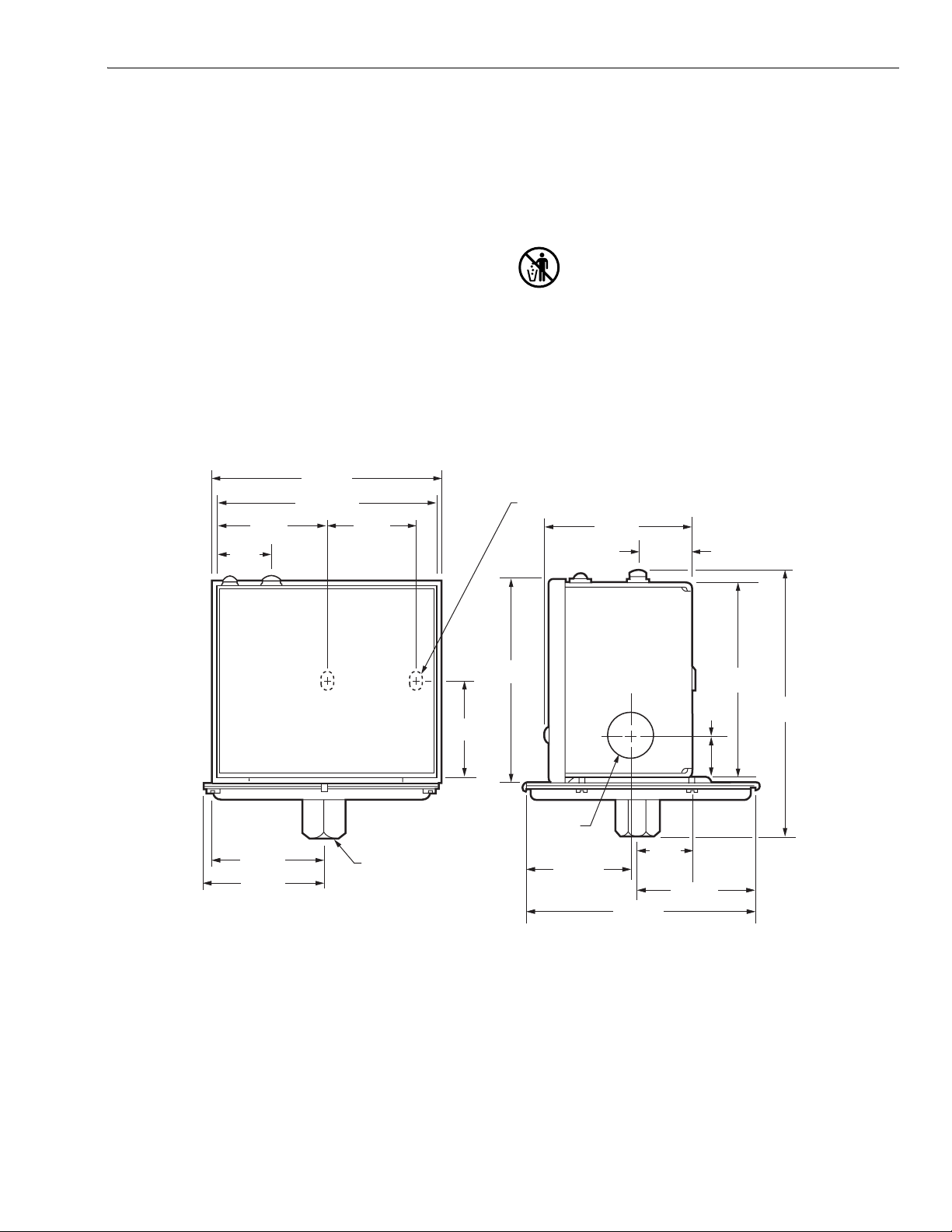
MERCURY NOTICE
If this control is replacing a control that contains
mercury in a sealed tube, do not place your old control
in the trash. Dispose of properly. This control also
contains mercury in a sealed tube. It must also be
disposed of properly when it is replaced.
Contact your local waste management authority for
instructions regarding recycling and the proper
disposal of an old control.
3/16 (9) x 21/64 (8) KNOCKOUT (2)
2-3/4 (70)
1-1/16 (27)
1-13/16
2-1/8 (54)
2-1/4 (57)
1/4 – 18 NPT
Fig. 1. Mounting dimensions of the L408A,B and L608A VaporStat® controllers in inches
(millimeters in parentheses).
INSTALLATION
When Installing This Product…
1. Read these instructions carefully. Failure to follow them
could damage the product or cause a hazardous
condition.
2. Check the ratings given in the instructions and on the
(46)
3-7/8
(98)
7/8
(22) DIA.
1-3/16 (30)
product to make sure the product is suitable for your
application.
4-1/2 (114)
1-1/16
(27)
2-1/4 (57)
13/16
(21)
3-23/32
(95)
5-1/8
(130
3. Installer must be a trained, experienced service
technician.
4. After installation is complete, check out product
operation as provided in these instructions.
3 60-2158—5
Page 4

L408A,B; L608A VAPORSTAT® CONTROLLERS
(
PRESSURE
A
WARNING
Electrical Shock Hazard.
Can cause severe injury, death or property
damage.
Disconnect the power supply before beginning
installation to prevent electrical shock or possible
equipment damage.
CAUTION
Equipment Damage Hazard.
Improper use with a compressor can damage the
controller.
When using the controller with a compressor, install a
dampening device (such as a needle valve, header, or
surge tank) to dampen pulsations that can damage the
controller or reduce its life.
IMPORTANT
1. Locate the controller where the ambient temperature
will not exceed 150°F (66°C).
2. Use pipe compound sparingly to avoid clogging the
hole in the pipe or diaphragm fitting.
3. Do not tighten the controller by hand by holding the
case.
4. The controller must be accurately leveled for proper
operation.
Location and Mounting
Leveling
A VaporStat® Controller must be accurately leveled for proper
operation. It is level when the leveling indicator hangs freely
with its pointer directly over the index mark inside on the back
of the case. Level the controller by carefully bending the
steam trap (siphon loop).
Mounting Alongside a Pressure Gauge
To mount the controller alongside a pressure gauge, remove
the gauge. In its place, install a steam trap (siphon loop) with a
tee on top. Using elbows and pipe nipples, mount the
controller and pressure gauge on the ends of the tee. See Fig.
2. Level the controller after installation.
GAUGE
1
2-1/4
(57.2)
DIA.
INCORRECT
4-1/2 TO 5-1/2
114.3 TO 139.7)
PRESSURE
CONTROLLER
TEE
CORRECT
14026
STEAM TRAP
(SIPHON LOOP)
NOTE: For most accurate operation, supplemental heat
BOILER
BOILER
should be added to installations where the
temperature falls below -20°F (-29°C). Never locate
1
the controller where the temperature falls below
-35°F (-37°C), as mercury in the switch will freeze at
this temperature.
When used with steam boilers, always mount the controller
above the water line in the boiler. A steam trap (siphon loop)
must always be connected between the controller and the
Fig. 2. Correct and incorrect mounting of a steam trap
(siphon loop) with approximate dimensions in inches
1/4 IN. BLACK IRON PIPE WITH 1/4 - 18 NPT EXTERNAL
TRHEADS ON BOTH ENDS. BEND THE STEAM TRAP
(SIPHON LOOP) TO LEVEL THE CONTROLLER.
(millimeters in parentheses).
M8934
boiler (see Fig. 2) to prevent boiler scale and corrosive vapors
from attacking the diaphragm. The loop on the steam trap
must always be perpendicular to the face of the controller. If
the loop is parallel to the controller, expansion or contraction
of the loop will tip the controller and cause the switch to
operate inaccurately.
The controller can be mounted (1) alongside the pressure
gauge, (2) in a fitting on the boiler provided by the
manufacturer, (3) at a remote location in case of excessive
vibration, or (4) in a special mounting on a low water cutoff.
Make all pipe connections in accordance with approved
standards. When making pipe connections, use pipe
compound sparingly to seal the joints. Excess pipe compound
may clog the small hole in the fitting and prevent the controller
from operating properly. To avoid leaks and damage to the
case, use a parallel jaw wrench on the controller hexagonal
Mounting on a Boiler
If it is not convenient to mount the controller alongside the
pressure gauge, install a steam trap (siphon loop) in the fitting
provided by the boiler manufacturer. Screw the controller
directly on the steam trap and level the controller.
Mounting at a Remote Location
If there is excessive vibration at the boiler which may
adversely affect the operation of the controller, the controller
should be mounted at a remote location.All piping from the
boiler must be suitable and solidly mounted. The piping must
be properly pitched to drain all condensation back to the
boiler. A steam trap (siphon loop) must be mounted between
the remote piping and the controller. Level the controller after
installation.
fitting. Do not tighten the controller by hand by holding the
case.
60-2158—5 4
Page 5

L408A,B; L608A VAPORSTAT® CONTROLLERS
L
(
D
D
SPDT
WIRING
WARNING
Electrical Shock Hazard.
Can cause severe injury, death or property
damage.
Disconnect the power supply before beginning wiring.
More than one disconnect may be required.
1. All wiring must comply with applicable electrical codes,
ordinances and regulations. Use NEC Class 1 (line
voltage) wiring.
2. For normal installations, use moisture-resistant NO. 14
wire suitable for at least 167°F (75°C) if you are using
the controller with a flame safeguard primary control or
at least 194°F (90°C) if you are using it with a
programming control.
3. For high temperature installations, use moisture-
resistant No. 14 wire, selected for a temperature rating
above the maximum operating temperature.
4. Disconnect the power supply before beginning wiring to
prevent electrical shock and equipment damage.
5. All models have a terminal block inside the cover (see
Fig. 3) and a 7/8 in. (22 mm) hole in one side for 1/2 in.
(13 mm) conduit, cable or wires. Remove the front cover
by loosening the screw at the bottom of the main scale.
6. Refer to Fig. 4 through 7 for typical hookups. Follow the
burner or boiler manufacturer wiring diagram, if
provided.
7. Make sure the loads do not exceed the Switch Contact
ratings in the Specifications section.
8. Replace the front cover when wiring is complete.
RISE
RISE
RISE
SPST
CONTROLLER
2
L1
(HOT)
POWER
SUPPLY
L2
1
L2
1
PROVIDE DISCONNECT MEANS AND OVERLOAD PROTECTION
AS REQUIRED.
HIGH LIMIT–L408A BREAKS WHEN PRESSURE RISES TO SET POINT.
2
LOW LIMIT–L408B BREAKS WHEN PRESSURE FALLS TO SET POINT
MINUS DIFFERENTIAL.
OPERATING CONTROLER–L408A BREAKS WHEN PRESSURE RISES
TO SET POINT, AND MAKES AGAIN WHEN PRESSURE FALLS TO
SET POINT MINUS DIFFERENTIAL.
FLAME
SAFEGUARD
CONTROL,
MOTOR, OR
OTHER LOAD
M19772
Fig. 4. L408 used as a limit or as an operating controller.
CONTROLLER
(HIGH LIMIT)
2
B
W
R
1
HOT)
POWER
SUPPLY
L2
1
L2
ALARM
FLAME
SAFEGUAR
CONTROL,
MOTOR, OR
OTHER LOA
1
PROVIDE DISCONNECT MEANS AND OVERLOAD PROTECTION
W
R
B
L408A L408B L608A
BREAKS ON
PRESSURE
RISE TO
SETPOINT
Fig. 3. L408A,B and L608A terminal blocks and internal
MAKES ON
PRESSURE
RISE TO
SETPOINT
schematics.
BREAKS R-B,
MAKES R-W ON
PRESSURE RISE
TO SETPOINT
M19771
Fig. 5. L608A used as a high limit, with an alarm circuit.
AS REQUIRED.
BREAKS R TO B AND MAKES R TO W WHEN PRESSURE
2
RISES TO SETPOINT.
M8938
5 60-2158—5
Page 6

L408A,B; L608A VAPORSTAT® CONTROLLERS
L
(
D
D
SPDT
9
MAIN SCALE SETPOINT
L
L
))
)
3
L
Y
MAIN SCALE
S
CONTROLLER
(LOW LIMIT)
2
B
W
R
1
HOT)
POWER
SUPPLY
L2
1
L2
FLAME
SAFEGUAR
CONTROL,
MOTOR, OR
OTHER LOA
the differential adjusting screw until the differential setting
indicator is at the desired value. The scales are marked in psi
and kg/cm
408A
2
.
PRESSURE
RISE
(SWITCH BREAKS)
SUBTRACTIVE
DIFFERENTIAL
DIFFERENTIAL SETTING
(SWITCH MAKES)
MAIN SCALE SETPOINT
(SWITCH MAKES)
ALARM
1
PROVIDE DISCONNECT MEANS AND OVERLOAD PROTECTION
AS REQUIRED.
BREAKS R TO W AND MAKES R TO B WHEN PRESSURE
2
FALLS TO SETPOINT MINUS DIFFERENTIAL.
M8937
Fig. 6. L608A used as a low limit, with an alarm circuit.
SPDT
CONTROLLER
W
2
B
L1
(HOT)
POWER
SUPPLY
1
2
1
L2
PROVIDE DISCONNECT MEANS AND OVERLOAD PROTECTION
AS REQUIRED.
BREAKS R TO B AND MAKES R TO W WHEN PRESSURE
RISES TO SETPOINT.
WHITE
RED
R
BLUE
BLACK
BLACK
LINE VOLTAGE
TWO-POSITION MOTOR
CLOSED
W1
(LOW FIRE)
R1
OPEN
B1
(HIGH FIRE)
L1
L2
M644B
M893
Fig. 7. L608A controlling an M644B Motor.
408B
608A
PRESSURE
RISE
PRESSURE
RISE
SUBTRACTIVE
DIFFERENTIAL
DIFFERENTIAL SETTING
(SWITCH BREAKS)
MAIN SCALE SETPOINT
(BREAKS R-B, MAKES R-W
SUBTRACTIVE
DIFFERENTIAL
DIFFERENTIAL SETTING
(MAKES R-B, BREAKS R-W
Fig. 8. L408A,B and L608A operating points.
DIFFERENTIAL
ADJUSTING
SCREW
CALEPLATES
DIFFERENTIAL
SETTING
INDICATOR
DIFF.
MAIN
3.5
3
12
.8
10
2.5
.7
.6
2
8
.5
1.5
6
.4
.3
4
1
.2
2
.5
.1
0
PSI
50
40
30
20
10
0
ADJUSTING
SCREW
M1977
MERCUR
SWITCH
SETTING AND CHECKOUT
Setting
In all models, the differential is subtractive from the main scale
setpoint. The upper operating point is determined by the main
scale setpoint, while the lower operating point is determined
MAIN SCALE
SETTING
INDICATOR
DIAPHRAGM
ASSEMBLY
LEVELING
INDICATOR
Fig. 9. Setting a VaporStat® Controller.
INDEX
MARK
POINTER
M19774
by the main scale setting less the differential setting.
Operating points are shown in Fig. 8.
Adjust the main scale setpoint for the desired operating
pressure by turning the main scale adjusting screw (see Fig.
9) on the top of the case until the main scale setting indicator
is at the desired value. Adjust the differential setting by turning
60-2158—5 6
Checkout
After the controller has been installed, wired, and set, it should
be tested with the system in operation. First allow the system
to stabilize. Then observe the operation of the controller while
rasing and lowering its setpoint. Pressure should increase
when the setpoint is raised and decrease when the setpoint is
lowered.
Page 7

Also check the make and break points of the controller. If they
M19775
do not agree with a separate, accurately calibrated, pressure
gauge, a slight adjustment of the scaleplate(s) may be
necessary.
Use accurate pressure testing equipment when checking out
the controller. Do not rely on inexpensive gauges. The
controllers are carefully calibrated at the factory.
Boiler Installation
If the controller is being used on a boiler installation, test it as
follows:
1. Note the boiler pressure by checking the boiler pressure
gauge. (To perform this test properly, the boiler should
have a pressure reading near the middle of the
controller main scale range.)
2. Turn the main scale adjusting screw (see Fig. 9) until
the main scale setting indicator on the controller
corresponds to the boiler pressure gauge reading.
3. The L408A should break the control circuit automatically
when the boiler pressure gauge reading equals or
slightly exceeds the controller setting.
OHMMETER
L408A,B; L608A VAPORSTAT® CONTROLLERS
DIFF.
MAIN
50
3.5
3
12
40
.8
10
2.5
.7
.6
30
2
8
.5
1.5
6
.4
20
.3
4
1
.2
10
2
.5
.1
0
0
PSI
W
R
B
SET POINT
DECREASE
NOTE: The L408B should make the circuit under the same
circumstances. The L608A should make the R-W
and break the R-B circuit under the same
circumstances.
4. If the controller is operating properly, turn the main scale
adjusting screw (see Fig. 9) until the main scale setting
indicator is at the desired setpoint.
If a Controller Seems to Operate Improperly
If the controller is suspected of operating improperly, it may be
checked further as follows (see Fig. 10):
1. Disconnect all power to the controller, loosen the cover
screw and remove the cover.
2. Disconnect the wires from the controller.
3. Connect an ohmmeter between the switch terminals.
4. Lower the setpoint of the controller (simulating a
pressure increase) through a range greater than the
differential. The switch should either make or break,
depending on the model of the controller. (An L408A
should break, an L408B should make, and an L608A
should break R-B and make R-W.) If it makes, the
ohmmeter will read zero; if it breaks, the ohmmeter will
read infinity.
5. Raise the setpoint of the controller (simulating a
pressure decrease) through a range greater than the
differential. The switch should break or make, just the
opposite of the result in step 4.
ZERO
ADJ
AN L608A IS SHOWN. AN L408 HAS ONLY 2 TERMINALS (SPST
1
SWITCHINGS); AN L408A WILL BREAK AND AN L408B WILL MAKE
WHEN THE SET POINT IS DECREASED FAR ENOUGH.
(ZERO OHMS WHEN R-W MAKES)
Fig. 10. Checking a VaporStat
INFINITY
®
controller.
CAUTION
Equipment Damage Hazard.
Failure to follow checkout instructions can
damage components or systems.
Do not put the system into service until you have
satisfactorily completed all applicable tests described
in this Checkout section, in the Checkout section of
the applicable instruction sheet for the flame
safeguard control,
SERVICE INFORMATION
Calibration
The controller was carefully calibrated during manufacture
and should not require recalibration. Most calibration errors
are caused by improper leveling. The controller should be
level if the pointer on the leveling indicator is directly over the
index mark (see Fig. 9). In some cases, the leveling indicator
may not be accurate enough. The pointer may be over the
index mark but the controller still may not be operating within
the tolerance of its scale setting. In that case, carefully bend
the steam trap (siphon loop) until the controller switches
properly.
7 60-2158—5
Page 8

L408A,B; L608A VAPORSTAT® CONTROLLERS
Maintenance
The cover of the controller should be in place at all times to
protect the internal components for dirt, dust, and physical
damage. Routine maintenance should consist of occasional
inspection and blowing or brushing away an accumulated dirt
and dust. To ensure proper functioning of the controller at all
times, an operational check of the entire system should be
performed during routine maintenance checks.
Automation and Control Solutions
Honeywell International Inc. Honeywell Limited-Honeywell Limitée
1985 Douglas Drive North 35 Dynamic Drive
Golden Valley, MN 55422 Scarborough, Ontario
60-2158—5 G.R. Rev. 10-03 www.honeywell.com
M1V 4Z9
Printed in U.S.A. on recycled
paper containing at least 10%
post-consumer paper fibers.
 Loading...