

Honeywell IS-215T Installation Instructions Manual
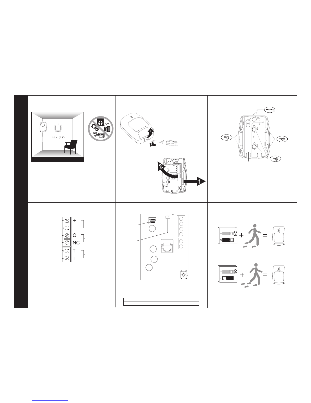
❶ Select the mounting location.
❹ Wire the unit.
❸ Mount the unit.
Mounting Location Guidelines
• 2.3 m (7’6”) mounting height
• Avoid direct or reflected sunlight
• Aim sensor away from windows or heating/
cooling devices
• Sensor must have a clear line-of-sight to
protected area
• Push outward on the
PCB latch and lift the
PCB out of the housing.
• Slide the wire through the wire channel and wire
access in the back housing.
• Mount the back housing flat against a wall or in a
corner.
• Replace the PCB.
•
Connect wires as shown using 0.64 - 1.63 mm
2
(14 to 22 AWG) wire size. Observe proper
polarity.
Corner
Mount
Wire Channel
Wall Mount
IS-215T Passive Infrared Motion Sensor Installation Instructions
❷ Separate the sensor housings and re-
move the printed circuit board (PCB).
Corner
Mount
Wiring Knockouts
POWER
12VDC
10mA
ALARM
16VDC
90mA
TAMPER
30VDC
0.5A
❺ Configure the sensor sensitivity.
• Configure the IS-215T for the sensitivity best
suited to the application.
ON
OFF
SENSITIVITY SWITCH SW2 POSITION
High (pulse count 1)
Low [Normal] (pulse count 2)
❻ Walk-test the sensor.
High Sensitivity: 2-4 Steps
(Pulse Count 1)
Switch
• Use a small screwdriver to
push in the housing latch
at the bottom of the sensor,
and gently pull apart the
housings.
Alarm
LED
Low [Normal] Sensitivity: 3-5 Steps
(Pulse Count 2)
© 2004 Honeywell International Inc. • Honeywell and IntelliSense are registered trademarks of Honeywell International Inc.
All other trademarks are the properties of their respective owners. All rights reserved.
IS-215T Passive Infrared Motion Sensor Product Information
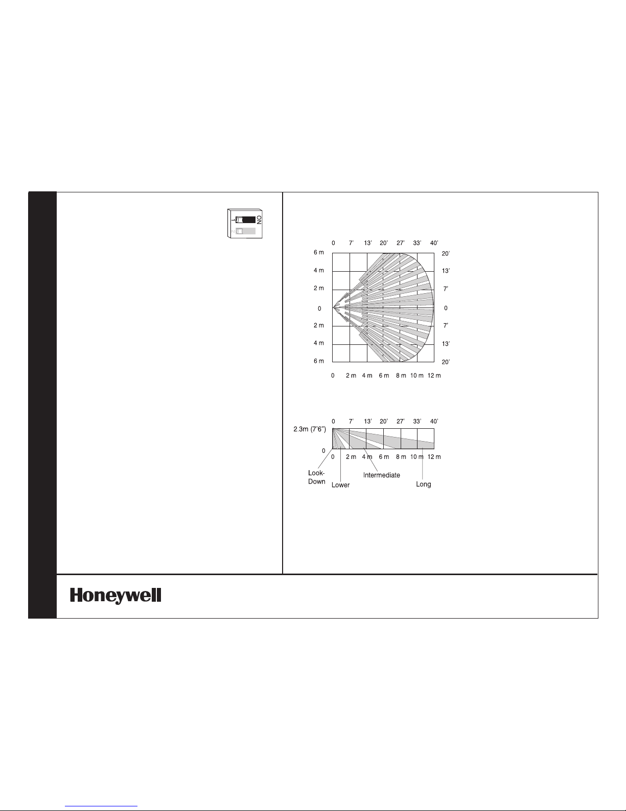
ALARM LED DISABLE
After walk-testing the sensor, disable the alarm
LED by turning Switch S1 to the OFF position.
SPECIFICATIONS
Range:
12 m x 12 m
40' x 40'
Power requirements:
10 - 14 VDC, w/LED - Alarm:
10mA max.; w/o LED - Alarm:
7mA max.; 12 VDC
3V peak-to-peak at nominal
12 VDC
Alarm relay:
Form A SPST,
90 mA, 16 VDC,
15 Ohm protective resistor
Tamper switch
Closed with cover in place
0.5 A, 30 VDC
RFI immunity:
30 V/m
10 MHz - 1000 MHz
PIR White light immunity:
6,500 Lux
PIR sensitivity:
Switch selectable
low [normal] (pulse count 2)
3-5 steps
high (pulse count 1) 2-4 steps
PIR fields of view:
dual element,
44 long range zones
14 intermediate, 8 lower,
4 look-down
Operating temperature:
-10
o
C to +55o C (14° F to 131° F)
Relative humidity:
5% to 95% noncondensing
Dimensions:
8.57 cm x 6.03 cm x 3.81 cm
(3-3/8" H x 2-3/8" W x 1-1/2" D)
Weight:
66.62 g (2.35 oz)
Packaged Product is 92.14 g
(3.25 oz)
Approvals/listings:
CE
cULus
C-Tick
EN 50131-1
Security Grade 2
Environmental Class II
Important: For UL Certificated installations, the IS215T must
be connected to a UL listed power supply or UL listed control
unit capable of providing a minimum of four hours of standby
power.
Suitable for connection to an EN 60950 Class II Limited Power
Source.
TOP VIEW
Wide Angle Lens
DETECTION PATTERNS
SIDE VIEW
Wide Angle Lens
5-051-680-40 Rev C
 Loading...