

Honeywell 3GL, 3GLC, ILP5 Installation Manual
3GL/3GLC GSM and ILP5 Ethernet Communications Module
Installation Guide
For Documentation and Online Support: http://www.security.honeywell.com/hsc/resources/MyWebTech
General Information
The 3GL/3GLC and ILP5 Communications Modules allow the LYNX Touch L5200/L5200CN and L7000/L7000CN controls
to communicate with the Central Station via the GSM cellular network or the Internet/Ethernet.
Installing the 3GL/3GLC in the LYNX Touch Series Control
IMPORTANT: Ensure that SIM card and the connector board are securely installed in the 3GL/3GLC before
installing the module in the control.
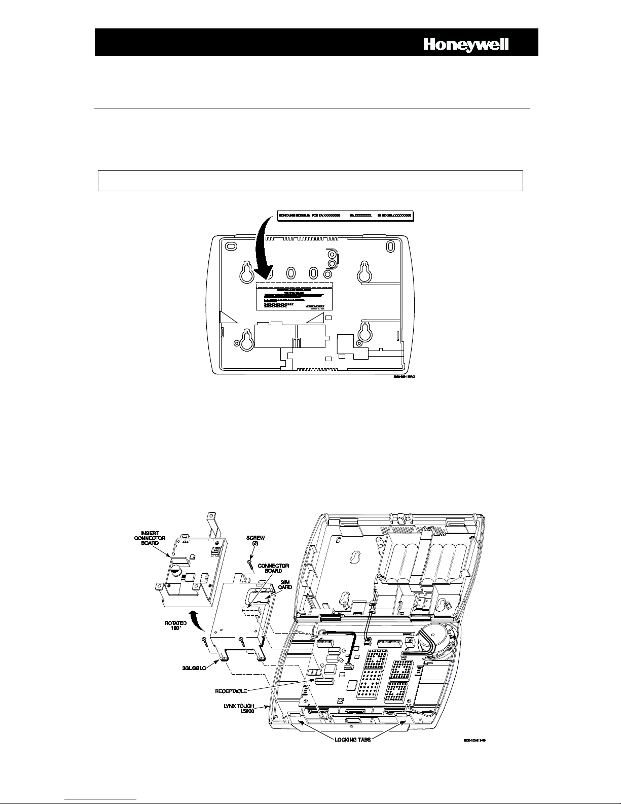
1. Install the provided FCC/IC label (800-19221) on the control’s case back (see diagram below).
Typical FCC/IC Label Location (L5200 shown)
2. Release the LYNX Touch front case from the back case by depressing the two locking tabs at the top of the unit with
the blade of a medium size screwdriver (see diagram below).
3. Install the 3GL/3GLC into the LYNX Touch control front case as shown. Ensure that the connector board is properly
seated into the receptacle on the control.
4. Secure the 3GL/3GLC with the three provided screws.
5. Enable the 3GL/3GLC device, configure alarm reporting and module supervision and register the device. Refer to the
“Program the Radio” and “Diagnostics” sections in the LYNX Touch Series Installation and Setup Guide (P/N 80016082 or higher).
Installing the 3GL/3GLC in the LYNX Touch (L5200 Shown)
Installing the ILP5 in the LYNX Touch Series Control
IMPORTANT: Ensure that the connector board and cable are securely installed in the ILP5 before installing
the module in the control.
1. Release the LYNX Touch front case from the back case by depressing the two locking tabs at the top of the unit with
the blade of a medium size screwdriver (see diagram below).
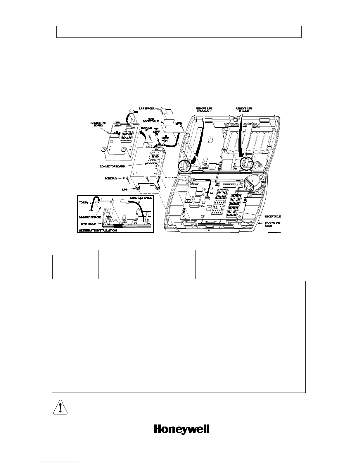
2. Using a wire cutter or knife cut the plastic tabs that secure the ILP5 spacer to the back case of the LYNX Touch.
3. Remove the ILP5 receptacle knockout from the left side of the LYNX Touch back case.
4. Install the ILP5 into the LYNX Touch control front case as shown. Ensure that the connector board is properly seated
into the receptacle on the control.
5. Secure the ILP5 with the three provided screws.
6. Insert the ILP5 receptacle and spacer into the slot on the back case.
7. Secure the communications cable to the tie wrap point on the ILP5 with the provided tie wrap.
8. Enable the ILP5, configure alarm reporting and module supervision and register the device. Refer to the “Program the
Radio” and “Diagnostics” sections in the LYNX Touch Series Installation and Setup Guide (P/N 800-16082 or higher).
Installing the ILP5 in the LYNX Touch (L5200 Shown)
Electrical Specifications
3GL/3GLC
ILP5
Voltage Input
5V (provided by the control panel)
5V (provided by the control panel)
Current
83 mA, 100 Base T with traffic, 41 mA , 10 Base T with traffic
Idle
15 mA, standby
Average
300mA, average transmit
Peak
1.6A peak transmit, 25% duty cycle
FEDERAL COMMUNICATIONS COMMISSION (FCC) STATEMENTS
The user shall not make any changes or modifications to the equipment unless authorized by the Installation Instructions or User's Manual. Unauthorized changes
or modifications could void the user's authority to operate the equipment.
FCC CLASS B STATEMENT
This equipment has been tested to FCC requirements and has been found acceptable for use. The FCC requires the following statement for your information:
This equipment generates and uses radio frequency energy and if not installed and used properly, that is, in strict accordance with the manufacturer's instructions,
may cause interference to radio and television reception. It has been type tested and found to comply with the limits for a Class B computing device in accordance
with the specifications in Part 15 of FCC Rules, which are designed to provide reasonable protection against such interference in a residential installation.
However, there is no guarantee that interference will not occur in a particular installation. If this equipment does cause interference to radio or television reception,
which can be determined by turning the equipment off and on, the user is encouraged to try to correct the interference by one or more of the following measures:
• If using an indoor antenna, have a quality outdoor antenna installed.
• Reorient the receiving antenna until interference is reduced or eliminated.
• Move the radio or television receiver away from the receiver/control.
• Move the antenna leads away from any wire runs to the receiver/control.
• Plug the receiver/control into a different outlet so that it and the radio or television receiver are on different branch circuits.
• Consult the dealer or an experienced radio/TV technician for help.
INDUSTRY CANADA CLASS B STATEMENT
This Class B digital apparatus complies with Canadian ICES-003.
Cet appareil numérique de la classe B est conforme à la norme NMB-003 du Canada.
FCC / IC STATEMENT
This device complies with Part 15 of the FCC Rules, and RSS 210 of IC. Operation is subject to the following two conditions: (1) This device may not cause
harmful interference (2) This device must accept any interference received, including interference that may cause undesired operation.
Cet appareil est conforme à la partie 15 des règles de la FCC & de RSS 210 des Industries Canada. Son fonctionnement est soumis aux conditions suivantes: (1)
Cet appareil ne doit pas causer d' interférences nuisibles. (2) Cet appareil doit accepter toute interférence reçue y compr is les interférences causant une réception
indésirable.
RF Exposure Warning
The antenna(s) used for this transmitter must be installed to provide a separation distance of at least 7.8 in (20 cm) from all persons and must not be
co-located or operated in conjunction with any other transmitter except in accordance with FCC multi-transmitter product procedures.
Mise en Garde
Exposition aux Frequences Radio: L'antenne (s) utilisée pour cet émetteur doit être installée à une distance de séparation d'au moins 7,8 pouces
(20 cm) de toutes les personnes.
Ê800-18964V1ÇŠ
800-18964V1 9/14 Rev. A
2 Corporate Center Drive, Suite 100
P.O. Box 9040, Melville, NY 11747
Copyright © 2014 Honeywell International Inc.
www.honeywell.com/security
 Loading...