

Page 1
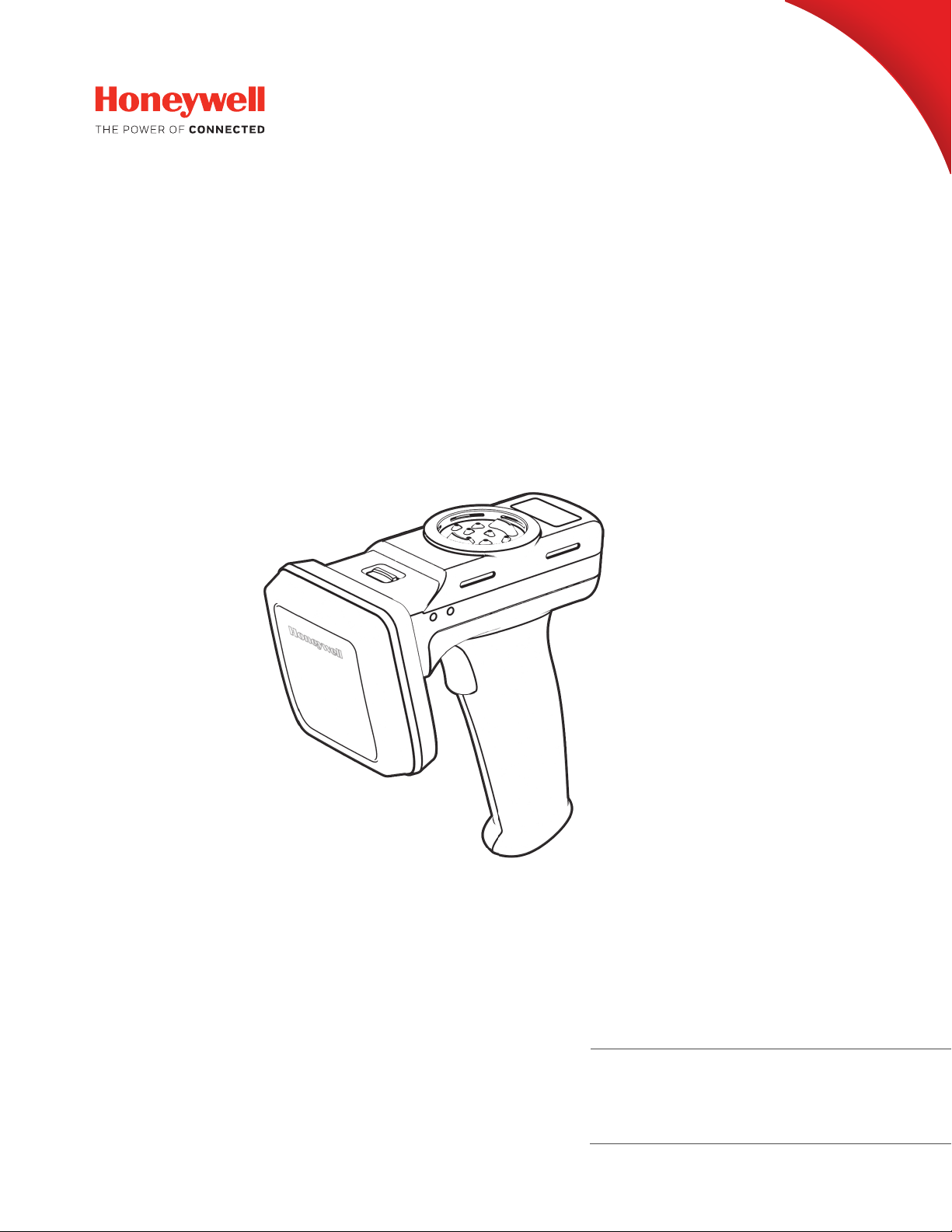
IH21
Bluetooth® UHF RFID Reader
User Guide
Page 2

Disclaimer
Honeywell International Inc. (“HII”) reserves the right to make changes in specifications and other information contained in
this document without prior notice, and the reader should in all cases consult HII to determine whether any such changes
have been made. The information in this publication does not represent a commitment on the part of HII.
HII shall not be liable for technical or editorial errors or omissions contained herein; nor for incidental or consequential
damages resulting from the furnishing, performance, or use of this material. HII disclaims all responsibility for the selection and use of software and/or hardware to achieve intended results.
This document contains proprietary information that is protected by copyright. All rights are reserved. No part of this document may be photocopied, reproduced, or translated into another language without the prior written consent of HII.
Copyright 2018 Honeywell International Inc. All rights reserved.
Web Address:
ePop-Loq®, TSL ASCII, and logos are registered trademarks owned by Technology Solutions (UK) Ltd (TSL®.)
Other product names or marks mentioned in this document may be trademarks or registered trademarks of other companies and are the property of their respective owners.
For patent information, refer to www.hsmpats.com.
www.honeywellaidc.com
Page 3

TABLE OF CONTENTS
Customer Support ........................................................................................................................ iii
Technical Assistance ............................................................................................................. iii
Product Service and Repair ................................................................................................ iii
Limited Warranty .................................................................................................................... iii
Send Feedback ........................................................................................................................ iii
Chapter 1 - Introduction..................................................................................1
IH21 Features.................................................................................................................................. 1
Battery Installation or Removal ................................................................................................ 2
Charging ............................................................................................................................................ 3
UHF Antenna Installation or Removal ................................................................................... 4
Locking the Antenna .............................................................................................................. 5
ePop-Loq®......................................................................................................................................... 5
Components ..............................................................................................................................5
Installation ................................................................................................................................. 6
Removal....................................................................................................................................... 6
Button Operation............................................................................................................................ 7
Reading Transponders................................................................................................................. 7
LED Status ........................................................................................................................................ 8
MicroSD Card................................................................................................................................... 9
Install a MircoSD Card........................................................................................................... 9
Remove a MicroSD Card .................................................................................................... 10
Auto Run File (AUTO.TXT).................................................................................................. 10
Log File (LOG.TXT) ............................................................................................................... 11
Software Development.............................................................................................................. 11
IH21 Bluetooth UHF RFID Reader i
Page 4

Chapter 2 - Connections ............................................................................... 13
Connecting with USB .................................................................................................................13
Overview.................................................................................................................................... 13
USB Operating Modes.........................................................................................................13
Changing the USB Operating Mode.............................................................................. 13
Connecting with Bluetooth® Wireless Technology ......................................................... 14
Comparison of Bluetooth Operating Modes..............................................................14
Change the Bluetooth Operating Modes ....................................................................15
Chapter 3 - Maintenance And Troubleshooting ...................................... 17
Maintenance.................................................................................................................................. 17
Troubleshooting ...........................................................................................................................17
ii IH21 Bluetooth UHF RFID Reader
Page 5

Customer Support
Technical Assistance
To search our knowledge base for a solution or to log in to the Technical Support
portal and report a problem, go to www.hsmcontactsupport.com.
For our latest contact information, see www.honeywellaidc.com/locations.
Product Service and Repair
Honeywell International Inc. provides service for all of its products through service
centers throughout the world. To obtain warranty or non-warranty service, return
your product to Honeywell (postage paid) with a copy of the dated purchase
record. To learn more, go to www.honeywellaidc.com and select Service & Repair at
the bottom of the page.
Limited Warranty
For warranty information, go to www.honeywellaidc.com and click Get Resources >
Product Warranty.
Send Feedback
Your feedback is crucial to the continual improvement of our documentation. To
provide feedback about this manual, contact the Honeywell Technical Communications department at [email protected].
IH21 Bluetooth UHF RFID Reader iii
Page 6

iv IH21 Bluetooth UHF RFID Reader
Page 7
CHAPTER
1
INTRODUCTION
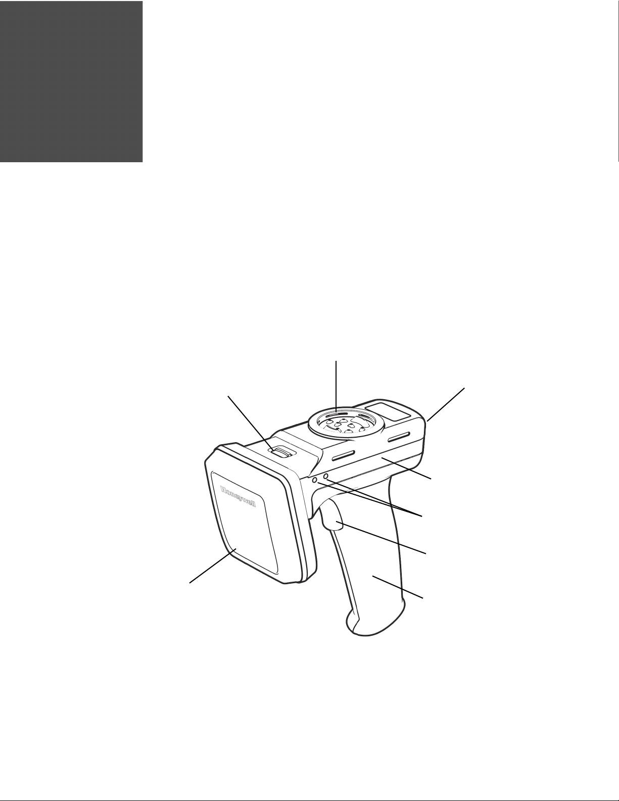
Antenna Release Latch
Main Body
Docking Connector
UHF Antenna
Status LEDs
Trigger Handle
ePop-Loq® socket
Trigger Button
Honeywell’s IH21 UHF Reader provides Ultra High Frequency (UHF) Radio Frequency Identification (RFID). The reader can be used stand alone or paired with a
Honeywell Mobility Computer. It can be used with UHF transponders including the
EPC Global Class 1 Generation 2 transponders.
IH21 Features
IH21 Bluetooth UHF RFID Reader 1
Page 8
Battery Installation or Removal
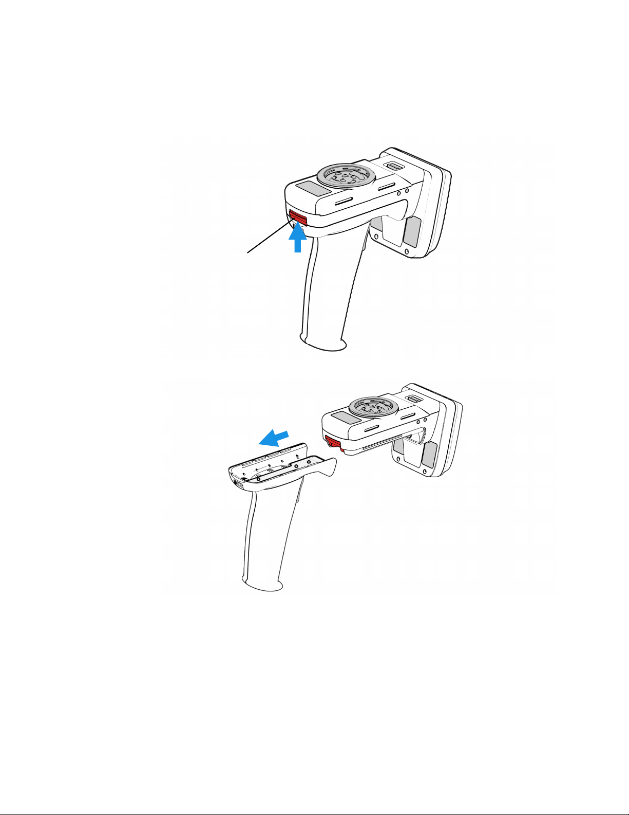
Trigger Handle
Release Latch
The battery is charged using a docking station and therefore is unlikely to need to
be changed once installed.
1. Push release latch up on the reader’s trigger handle.
2. Slide handle back.
2 IH21 Bluetooth UHF RFID Reader
Page 9
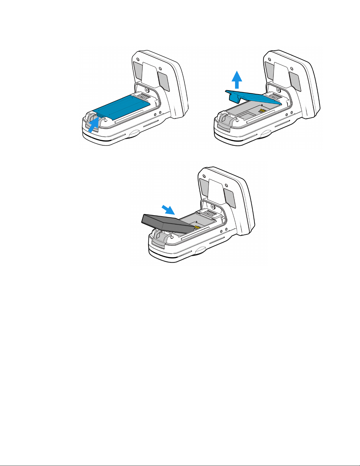
3. Remove battery cover. Push battery cover toward the UHF Antenna, and then
lift battery cover up.
4. Insert the top end of the battery into the reader, and press battery down.
5. Attach the battery cover. Make sure that the cover clicks into place.
6. Attach the handle. Make sure that the handle clicks into place.
Charging
To comply with international shipping regulations, the battery is discharged to less
than 30% of their maximum capacity. It is therefore recommended that you fully
charge the battery before using the reader for the first time.
IH21 Bluetooth UHF RFID Reader 3
Page 10
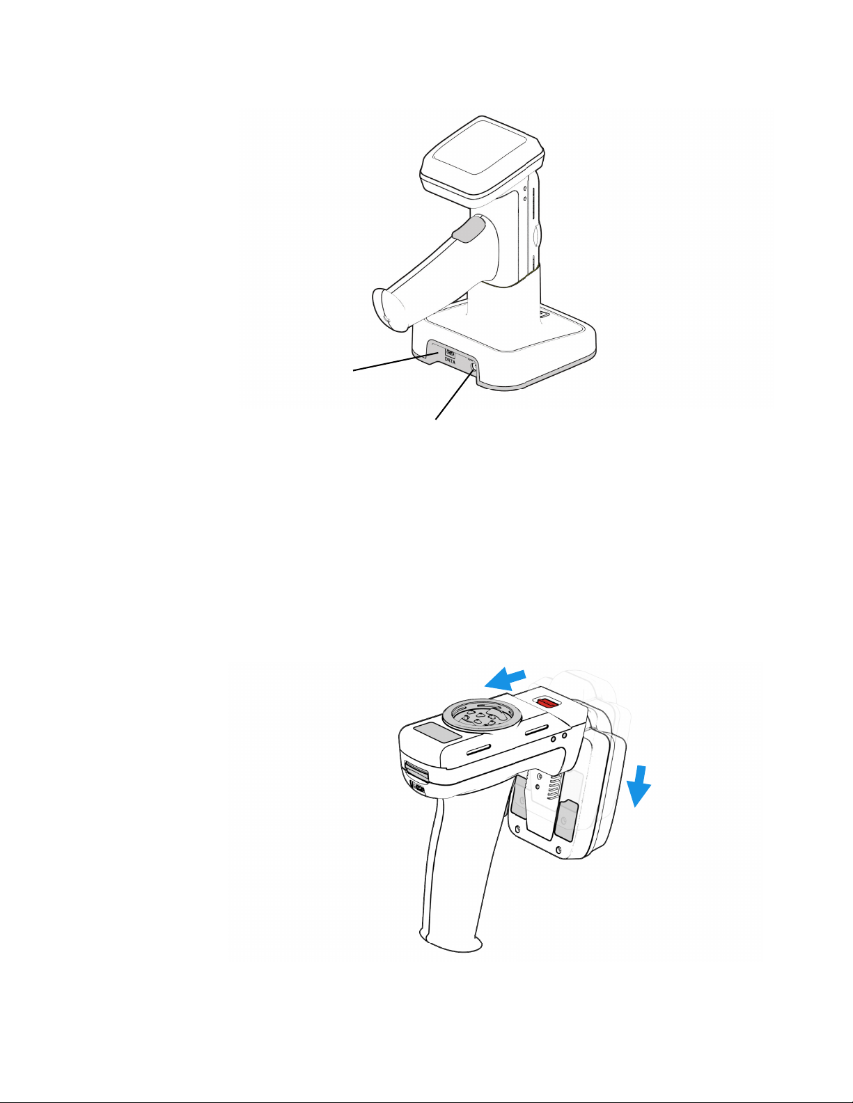
The reader can be charged using the dedicated IH21 docking station. The docking
USB Port
DC Power Jack
station has inputs for power and mini USB.
UHF Antenna Installation or Removal
The UHF antenna can be detached from the main body of the reader.
1. Remove the Honeywell mobility device from the reader.
2. Turn off power to the reader.
3. At the same time, press the antenna release latch back and pull the antenna
downward.
4 IH21 Bluetooth UHF RFID Reader
Page 11
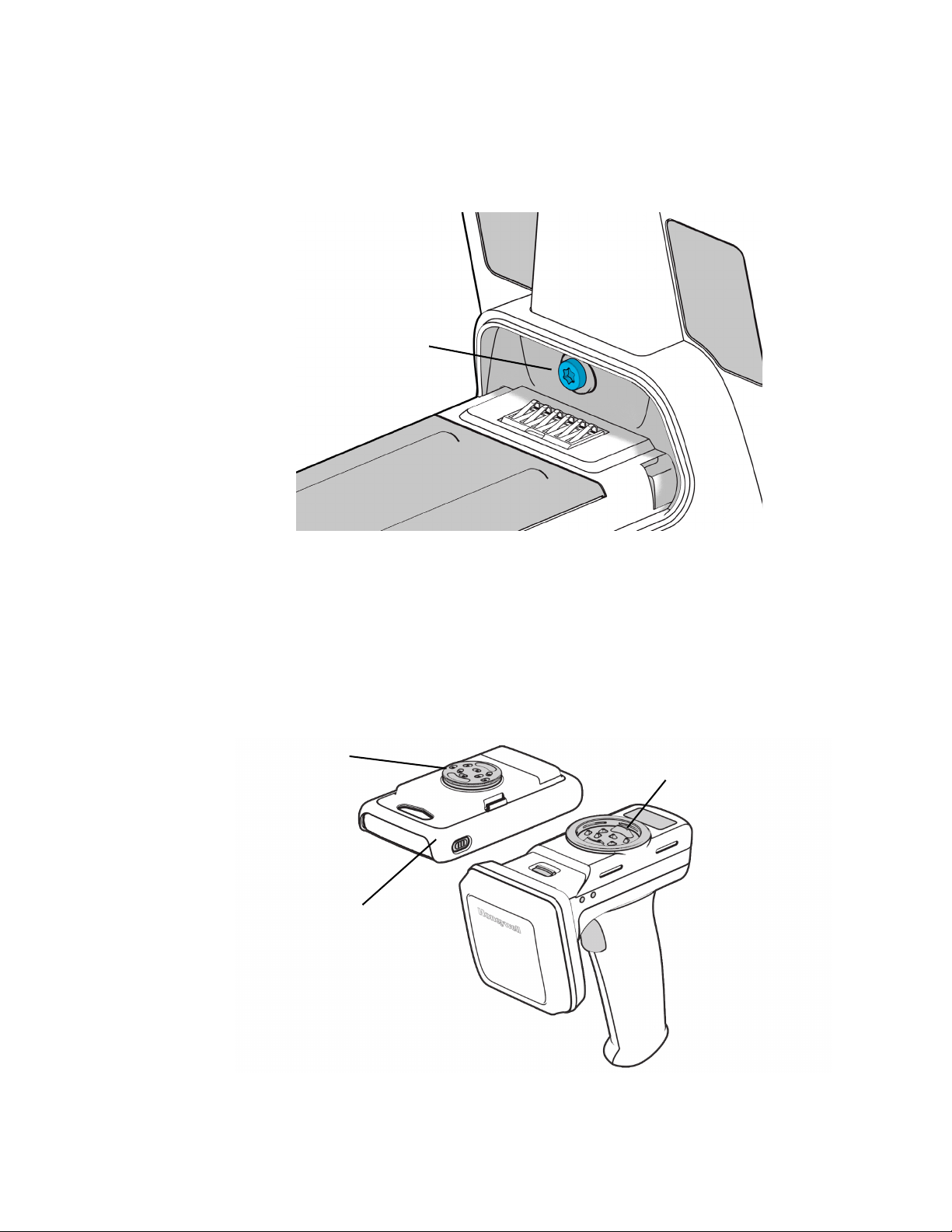
Locking the Antenna
Insert Screw Here
ePop-Loq case
ePop-Loq stud
ePop-Loq socket
The antenna can be locked into position.
1. Remove the reader’s trigger handle.
2. Insert a M2.5x5mm Torx pan head screw into the handle and antenna.
3. Attach the handle.
ePop-Loq®
Components
IH21 Bluetooth UHF RFID Reader 5
Page 12
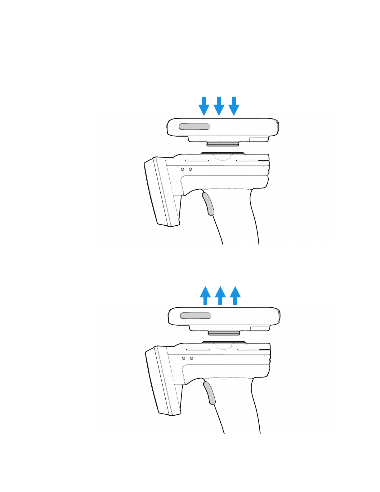
Installation
1. Ensure the mobility computer is fitted into the ePop-Loq case.
2. Check the socket and stud are clean and free from dirt or debris.
3. Align the stud with the socket, ensuring that it is parallel, and press the two
parts together firmly until they click into place.
Removal
Pull the case parallel away from the reader. Do not twist devices when separating.
6 IH21 Bluetooth UHF RFID Reader
Page 13

Button Operation
The default configuration of the reader scans for UHF transponders as the primary
function. The reader will continue to scan for UHF transponders while the button is
pressed. It will stop scanning once the button is released (and the current operation completes.)
• To initiate, press and hold the trigger button.
• To terminate, release the trigger button.
Reading Transponders
RFID transponders can be read when they are in range of the antenna. The antenna
is located on the front of the reader. The range at which a transponder can be read
depends on the transponder type and size and the number of transponders in the
field.
IH21 Bluetooth UHF RFID Reader 7
Page 14
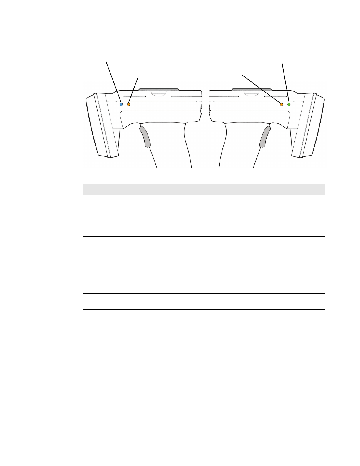
LED Status
Charge Status
Charge Status
Bluetooth Status
Read Indicator
LED Status
Blue slow flash (50% on, 50% off) The reader is awake, but there is no
connection.
Blue constant The reader is awake and connected to a host.
Short green flash The reader has successfully read a tag,
barcode, or executed the alert command.
Green slow flash (50% on, 50% off) Antenna error.
Orange slow flash (50% on, 50% off) Battery low warning (<10% capacity
remaining.) Recharge immediately.
Orange short single slow flash Battery charging with battery level less than
33%.
Orange short double flash Battery charging with battery level less than or
equal to 66%.
Orange short triple flash Battery charging with battery level greater than
or equal to 66%.
Orange rapid flash There is a charge error/battery fault.
Orange constant The reader is fully charged.
All off The reader is off and not charging.
8 IH21 Bluetooth UHF RFID Reader
Page 15
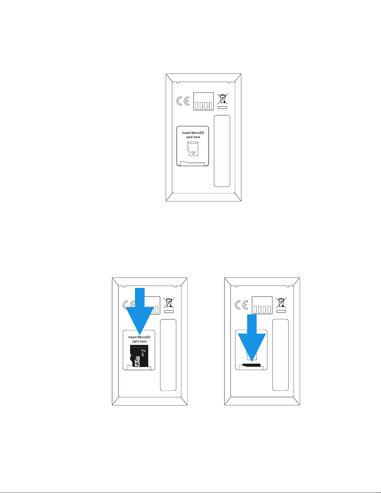
MicroSD Card
A microSD card can be installed in the reader. The card should be SD/SDHC compatible, FAT16 or FAT32, and up to 32 GB.
Install a MircoSD Card
1. Remove the trigger handle.
2. Remove the battery cover and battery.
3. Slide the microSD card into the marked slot, and then push and release the
microSD card to lock it into place.
4. Install the battery.
5. Attach the handle.
IH21 Bluetooth UHF RFID Reader 9
Page 16

Remove a MicroSD Card
1. Remove the trigger handle.
2. Remove the battery cover and battery.
3. Push and release the microSD card. The card will eject and can be removed.
Auto Run File (AUTO.TXT)
Once a SD card is installed, an Auto Run file can be created on the SD card. The
Auto Run file contains a list of ASCII commands that are executed as the reader
powers up. The file should be located at the root of the card and called “AUTO.TXT.”
Although the file can contain any valid ASCII 2 commands, one per line, it is
intended that these have the take no action ‘-x’ flag specified to allow the default
parameters for any command to be changed from the firmware defaults as the unit
boots without actually executing the command.
Example: To change the carrier power of the inventory command from 29dBm to 20dm
‘.iv -o20 -x’ would be appended to the Auto Run file. As the behavior with command
parameters this will set the output power for the inventory command until a new
value is send with this command. Therefore, the inventories executed by the trigger,
which executes ‘.iv’ will use the modified output power.
The Auto Run file can be manually created on the card before it is inserted into the
reader or the ASCII 2 command Write Command to Auto Run File ‘.wa’ can be used.
The Read Auto Run File ‘.ra’ can be used to read back the contents of the Auto Run
file or delete the file from the card.
10 IH21 Bluetooth UHF RFID Reader
Page 17

Log File (LOG.TXT)
Once a SD card is installed and logging is enabled a log file is created on the SD
card. The file is located at the root of the card and called “LOG.TXT.” All the lines
from every response to every command that is executed by the reader (including
those performed from trigger actions) are appended to the end of the file. Events
such as Power Up are also appended to the file.
The ASCII 2 Read Log File command (‘.rl’) is provided to enable or disable logging,
to read the log file from the card or to delete the log file from the card.
Note: The log file can quickly become large relative to the speed at which it can be
downloaded using the Read Log File Command.
Start of a sample log output:
DT: 2013-11-15t16:46:58
EV: Log File created
CS: .ws -sa4 -sbepc -ds300833B2DDD9014000000000 -s106 -so0002 -
sts2 -dbepc -da330DE29525C0210005F5F88A -d106 -do002
WW: 0
ME: No Transponder Found
ER: 005
DT: 2013-11-15T17:58:28
EV: Disconnected
DT: 2013-11-15T17:59:28
EV: Sleep
DT: 2013-11-18T09:18:21
EV: Wake up
CS: .al -dlon
OK:
DT: 2013-11-18T09:19:22
EV: Sleep
DT: 2013-11-18T10:07:42
EV: Wake up
DT: 2013-11-18T10:07:42
EV: Connected USB
CS: .al -dlon
OK:
CS: .iv LCMD 000000-qss0 -qta
EP: 330DE29525C0210005F5F8F2
EP: 221001500000000000000027
OK:
Software Development
To make full use of the functionality of the reader, a customized software application will be required.
IH21 Bluetooth UHF RFID Reader 11
Page 18

The reader incorporates TSL’s unique ASCII protocol for faster and easier application development. This sophisticated parameterized ASCII protocol provides the
developer a powerful set of commands that carry out multiple actions locally within
the Bluetooth reader. This approach enables multiple tag operation executed using
simple pre-configured ASCII commands while not only speeds integration of the
reader into applications, but also abstracts the developer from some of the complexities of the underlying Native API. Simple, text based commands are sent to the
reader and responses are returned as text. This allows straightforward access to
RFID tag functions such as inventory, read, and write.
12 IH21 Bluetooth UHF RFID Reader
Page 19

CHAPTER
2
CONNECTIONS
Connecting with USB
Overview
The IH21 UHF Reader has an ePop-Loq® mount which allows compatible devices
with custom applications to communicate with the reader via USB instead of Blue-
tooth®.
• USB connection will be passed through ePop-Loq to the attached device (via the
ePop-Loq case.)
• USB connection to the reader requires a custom application that supports the
ASCII protocol over USB.
• If the reader is placed into the charge cradle with an attached ePop-Loq mobility
device, the USB will be disconnected, and both the IH21 and the device will
charge.
USB Operating Modes
The ePop-Loq on the reader may operate in two modes. Charge-Only or Chargeand-Data:
• Charge-Only: The mobility device mounted will charge when the reader is placed
in the charging cradle, but will never use the USB data connection
• Charge-and-Data: The mobility device will use the USB data connection when
not in the charging cradle.
Note: The USB connector on the charging cradle is always available when the reader is
docked.
Changing the USB Operating Mode
The factory default mode is Charge-Only.
IH21 Bluetooth UHF RFID Reader 13
Page 20

The USB operating mode maybe changed by adding commands to an AUTO.TXT
file placed in the root directory of the microSD card in the reader.
Note: The ePop-Loq USB mode is non-volatile and the command may be safely removed
from the AUTO.TXT file after it has been run once.
Set USB mode to Charge-Only
1. Create a blank AUTO.TXT file.
2. Add the following command (without quotations): “.fd -ep co”.
3. Place the file within the root directory of the microSD card in the reader.
4. Restart the reader.
Set USB mode to Charge-and-Data
1. Create a blank AUTO.TXT file.
2. Add the following command (without quotations): “.fd -ep cd”.
3. Place the file within the root directory of the microSD card in the reader.
4. Restart the reader.
Connecting with Bluetooth® Wireless Technology
Comparison of Bluetooth Operating Modes
The reader supports two modes of operation over Bluetooth. When connected via
USB the reader always supports the ASCII 2 protocol, but when connected over
Bluetooth the reader can either be set to use the ASCII 2 protocol (Bluetooth SPP
Mode) or it can appear as a Bluetooth keyboard (Bluetooth HID Mode.)
Bluetooth® SPP Mode Bluetooth® HID Mode
Apps need to be written with specific support
for the reader.
The reader can be discovered and paired in the
Bluetooth Settings or from within the App, but
when the App controls the connection:
• Connects when instructed by the App.
• Disconnects when instructed by the App.
• The reader powers off when no longer
connected and idle.
• The App needs to connect to restore.
Apps receive and interpret ASCII 2 Protocol
responses when the user triggers a UHF or
barcode scan.
Apps can use the reader without modification.
Reader is discovered and paired in the Host
Bluetooth Settings (often appears as a
Keyboard):
• After pairing the reader connects
automatically.
• If idle, the reader sleeps and the
connection is dropped.
• The reader, when woken, automatically
reconnects to the host device.
Apps receive input as key strokes from the
reader, including tab and return/enter keys.
14 IH21 Bluetooth UHF RFID Reader
Page 21

Bluetooth® SPP Mode Bluetooth® HID Mode
The App can respond and react intelligently to
responses.
• Duplicate responses can be ignored or
counted.
• Incoming tag data can be truncated,
stripped, or transformed into alternative
representations: Hex, ASCII, GS1 EPC URI,
etc..
The App can change the readers behavior. The reader can only send scanned data to the
The reader’s behavior and command
parameters are controlled in real time by the
App, e.g. the trigger action can change to suit
the task that the user is performing; the App
can allow the user to specify inventory output
power.
Configuration is held within the App (an
configuration in the AUTO.TST is likely to be
overridden by the App settings.)
All read activity, by default, is saved to a log file
if an SD Card is fitted.
The reader types text for each barcode/UHF
scan received.
• The tag values can be returned in Hex or
ASCII representations.
• Up to two additional characters can be
inserted before and after the text sent.
• The reader cannot truncate or strip values
from tag data.
host. The host cannot change the reader’s
behavior.
The reader’s behavior, such as the action of the
reader’s trigger switch, the inventory output
power the idle sleep timeout, and other
command parameters can be configured only
once at start-up.
All configuration is held in an AUTO.TXT file
stored on a SD card. Removing the SD card or
deleting the AUTO.TXT and power-cycling the
unit restores default settings.
All reader activity, by default, is saved to a log
file if a SD card is fitted.
Change the Bluetooth Operating Modes
The IH21 reader can be operated in SPP mode where the reader is controlled by a
custom written application or in HID mode, where the reader behaves like a Blue-
tooth keyboard.
Preparation
Download and install the “PC Firmware Downloader” from Honeywell’s website at
www.honeywellaidc.com.
Switch to Bluetooth HID Mode
1. Delete existing pairings to the reader.
2. Launch the firmware downloader (Desktop Firmware Loader.)
3. Connect the reader to the computer via USB. The driver should install
automatically and the downloader should prompt as the com port arrives and
select the com port automatically (“COMn arrived.)
4. Select Action > Reset Bluetooth to HID mode.
5. Disconnect the reader from the computer.
6. Wake the reader by pulling the trigger. The blue LED will flash.
IH21 Bluetooth UHF RFID Reader 15
Page 22

7. Pair to the reader on the device.
8. Scanned data should now be typed into the current application on the device.
Switch to Bluetooth SSP Mode
1. Delete existing pairings to the reader.
2. Launch the firmware downloader (Desktop Firmware Loader.)
3. Connect the reader to the computer via USB. The driver should install
automatically and the downloader should prompt as the com port arrives and
select the com port automatically (“COMn arrived.)
4. Select Action > Reset Bluetooth to SPP mode (wait for the process to
complete.)
5. Disconnect the reader from the computer.
6. Wake the reader by pulling the trigger. The blue LED will flash.
7. Pair to the reader on the device.
8. Launch an Application (e.g. RFID Explorer) to use the reader.
16 IH21 Bluetooth UHF RFID Reader
Page 23

CHAPTER
3
MAINTENANCE AND TROUBLESHOOTING
Maintenance
For trouble-free service please observe the following tip when using the IH21
Reader:
• Protect the IH21 Reader from temperature extremes. Do not leave it on the
dashboard of a car on a hot day and keep it away from heat sources.
Troubleshooting
Symptoms Possible Cause Action
Nothing happens when the
button is pressed.
The orange LED flashes rapidly
when charging.
The host Bluetooth® discovery
does not find the reader.
Opening the Bluetooth virtual
com port does not connect to
the reader.
If the LEDs are not on, then the
battery may need to be
charged.
The reader may have button
actions disabled.
There is a battery fault. Replace the battery pack.
The battery pack temperature
is outside recommended limits.
The reader has powered off. Press the button and ensure
The reader is out of range. Move the reader closer to the
The Bluetooth® friendly name
of the reader has been
changed.
The host has paired to a
different Bluetooth device.
The host Bluetooth function
has an error.
Charge the reader.
Check the reader configuration
and restore to defaults.
Ensure charging only occurs
between 41°F and 104°F (5°C
and 40°C.)
the blue LED is flashing.
host.
Check the Bluetooth friendly
name or restore the reader to
factory defaults.
Pair to the required reader.
Warm boot the host. If this
does not help, delete the reader
from the favorites list and repair.
IH21 Bluetooth UHF RFID Reader 17
Page 24

Symptoms Possible Cause Action
Bluetooth pairing fails. The PIN on the reader has been
changed.
Other symptoms. Other fault. Run ASCII Remote Diagnostic
Set the Bluetooth PIN to a
known value.
and contact Support.
18 IH21 Bluetooth UHF RFID Reader
Page 25

Page 26

™
Honeywell
9680 Old Bailes Road
Fort Mill, SC 29707
www.honeywellaidc.com
IH21-EN-UG REV A
08/18
 Loading...