

Page 1

HVE1/HVE4/HVE8
Audio/Video Encoder
Audio/Video Encoder
HVE1 HVE1X
HVE4 HVE4X
HVE8 HVE8X
Getting Started Guide
Document 800-15611V2 – Rev A – 10/2013
Page 2

Revisions
Issue Date Revisions
A 08/2013 New document
V1 Rev A 10/2013 Removed Preliminary status. Adjusted alignment and layout. Minor text changes
throughout.
V2 Rev A 10/2013 Replaced the photo of the HVE8(X) back panel. Corrected the callouts in Fig 3.
Removed references to the microSD card and PoE for HVE8(X). Replaced "SADP
(IP finder) software" with "IP Utility".
Page 3
Cautions and Warnings
CAUTION
THIS SYMBOL INDICA TESTHAT
DANGEROUSVOLTAGE
CONSTITUTING A RISKOF
ELECTRIC SHOCK ISPRESENT
WITHIN THE UNIT.
CAUTION:TO REDUCE THE RISK OF ELECTRIC
SHOCK, DO NOT REMOVETHE COVER.
NO USER-SERVICEABLE PARTS INSIDE.
REFER SERVICING TOQUALIFIED SERVICE
PERSONNEL.
THIS SYMBOL INDICA TESTHAT
IMPORTANT OPERATING AND•
MAINTENANCE INSTRUCTIONS
ACCOMPANY THIS UNIT.
RISK OF ELECTRIC
SHOCK
DO NOT OPEN
Installation and servicing should be performed only by qualified and experienced technicians to conform to all local
codes and to maintain your warranty.
CAUTION 12 V DC models require the use of CSA Certified/UL Listed Class 2 power
adapters to ensure compliance with electrical safety standards.
Regulatory Statements
FCC Compliance Statement
Information to the User: This equipment has been tested and found to comply with the limits for a Class A digital
device, pursuant to part 15 of the FCC Rules. These limits are designed to provide reasonable protection against
harmful interference when the equipment is operated in a commercial environment. This equipment generates, uses,
and can radiate radio frequency energy and, if not installed and used in accordance with the instruction manual, may
cause harmful interference to radio communications. Operation of this equipment in a residential area is likely to cause
harmful interference in which case the user will be required to correct the interference at his own expense.
Canadian Compliance Statement
This Class A digital apparatus complies with Canadian ICES-003.
Cet appareil numérique de la Classe A est conforme à la norme NMB-003 du Canada.
Note Changes or modifications not expressly approved by the party responsible for
compliance could void the user’s authority to operate the equipment.
Document 800-15611V2 Rev A
10/2013
Page 4
10 | HVE1/HVE4/HVE8 Encoders Getting Started Guide
Manufacturer’s Declaration of Conformance
North America
The equipment supplied with this guide conforms to UL 60950-1 and CSA C22.2 No. 60950-1.
Europe
The manufacturer declares that the equipment supplied is compliant with the essential requirements of the EMC
directive 2004/108/EC, conforming to the requirements of standards EN 55022 for emissions, EN 50130-4 for immunity,
and EN 60950 for electrical equipment safety.
Waste Electrical and Electronic Equipment (WEEE)
Correct Disposal of this Product (applicable in the European Union and other
European countries with separate collection systems).
This product should be disposed of, at the end of its useful life, as per applicable
local laws, regulations, and procedures.
Important Safeguards
BEFORE OPERATING OR INSTALLING THE UNIT, READ AND FOLLOW ALL INSTRUCTIONS.
AFTER INSTALLATION, retain the safety and operating instructions for future reference
1. HEED WARNINGS - Adhere to all warnings on the unit and in the operating instructions.
2. INSTALLATION
• Install in accordance with the manufacturer’s instructions.
• Installation and servicing should be performed only by qualified and experienced technicians to conform to
all local codes and to maintain your warranty.
• Do not install the unit in an extremely hot or humid location, or in a place subject to dust or mechanical
vibration. The unit is not designed to be waterproof. Exposure to rain or water may damage the unit.
• Any wall or ceiling mounting of the product should follow the manufacturer’s instructions and use a
mounting kit approved or recommended by the manufacturer.
3. POWER SOURCES - This product should be operated only from the type of power source indicated on the
marking label. If you are not sure of the type of power supplied to your facility, consult your product dealer or
local power company.
4. HEAT - Situate away from items that produce heat or are heat sources such as radiators, heat registers, stoves,
or other products (including amplifiers).
www.honeywell.com/security
Page 5

| 11
5. WATER AND MOISTURE - Do not use this unit near water or in an unprotected outdoor installation, or any area
classified as a wet location.
6. MOUNTING SYSTEM - Use only with a mounting system recommended by the manufacturer, or sold with the
product.
7. ATTACHMENTS - Do not use attachments not recommended by the product manufacturer as they may result in
the risk of fire, electric shock, or injury to persons.
8. ACCESSORIES - Only use accessories specified by the manufacturer.
9. CLEANING - Do not use liquid cleaners or aerosol cleaners. Use a damp cloth for cleaning.
10. SERVICING - Do not attempt to service this unit yourself as opening or removing covers may expose you to
dangerous voltage or other hazards. Refer all servicing to qualified service personnel.
11. REPLACEMENT PARTS - When replacement parts are required, be sure the service technician has used
replacement parts specified by the manufacturer or have the same characteristics as the original part.
Unauthorized substitutions may result in fire, electric shock or other hazards.
Installation
The HVE1(X)/HVE4(X)/HVE8(X) encoders are highly advanced surveillance equipment that should be installed with
care. Please ensure that you install a manufacturer-recommended HDD (HVE8(X) models only). See Table 1-1 for a list
of recommended HDDs.
During encoder installation:
• Use brackets for racking mounting.
• Ensure that there is ample room for audio and video cables.
• When installing the cables, ensure that the bend radius of the cables is no less than five times its diameter.
• Connect both the alarm and the RS-485 cable.
• Allow at least 2cm (~0.75 inch) of space between rack-mounted devices.
• Ensure that the encoder is grounded.
• Ensure that the environmental temperature is within -10°C–55°C (14°F–131°F).
• Ensure that the environmental humidity is within 10%–90%.
Installing the Hard Disk Drive (HDD)
This section applies only to HVE8(X) models that have room for a Hard Disk Drive (HDD) for recording.
Preparing for Installation
This encoder comes from the factory without a HDD. Follow these instructions to install a HDD that is appropriate for
your situation according to the total capacity calculated in terms of the Schedule Recording Settings. The installation
and removal of the hard disk should be done by qualified professionals.
800-15611V2 - A - 10/2013
Page 6

12 | HVE1/HVE4/HVE8 Encoders Getting Started Guide
Before installing a HDD for HVE(X), please ensure the power is disconnected from the device. Only a
factory-recommended HDD should be used for this installation.
Table 1 Tested Compatible HDDs
SEAGATE
Capacity HDD Model
3T ST3000VX000-9YW1
ST2000VX000-9YW1
2T ST2000VX002-1AH1
ST2000VM003-1CT1
ST1000VM002-9ZL1
1T ST31000322CS
ST1000VX000-9YW1
ST31000526SV
500G ST3500410SV
ST3500411SV
ST3250312CS
250G ST3250310SV
ST3250820SV
WD
Capacity HDD Model
2T WD20EURS-63S
1T WDC WD10EVDS-63U
Required Tools: Screwdriver
Installing the HDD
1. Use the screwdriver to unfasten the screws on both sides and the rear panel of the encoder, then remove the
cover from the chassis and set aside.
www.honeywell.com/security
Page 7

| 13
Install Secure
Connect the power cord Connect the data line
Figure 1 Removing the Cover
2. Place the HDD into the slot on the chassis, and then secure it in position by tightening the screws at the bottom
of the chassis.
Figure 2 Installing and Securing the HDD
3. Remove the HDD data line from the accessories box. Plug one end of the data line to the circuit board, and the
other end to the data line port on the HDD. Connect the power cord to the HDD in the same way.
Figure 3 Connecting the Data Line and the Power Cord
4. Replace the chassis cover, and then tighten the screws on both sides and the rear panel of the encoder.
800-15611V2 - A - 10/2013
Page 8

14 | HVE1/HVE4/HVE8 Encoders Getting Started Guide
About the Encoder
HVE1(X)
Front Panel
Figure 4 HVE1 Front Panel
Table 2 HVE1 Front Panel
Interface Element Function
1 PWR LED Indicator Lights red when the device is powered on.
Lights orange when an SD card is inserted.
2 VIDEO IN BNC connector for video input.
3 LINE IN 3.5mm connector for two-way audio input. Connect to an audio input
device or an active pick-up, a microphone, etc.
4 AUDIO OUT 3.5mm connector for audio output. Connect an audio output device,
such as a loudspeaker.
5 microSD microSD interface for data storage, up to 32GB, Class 6 and above.
6 RESET Restore to the factory default settings by holding the RESET button for
more than 15 seconds after the power is turned on.
www.honeywell.com/security
Page 9

Rear Panel
| 15
Figure 5 HVE1 Rear Panel
Table 3 HVE1 Rear Panel
Interface Element Function
1 ALARM IN/OUT Relay alarm input/output. The maximum voltage/current supported
by the relay output is 12 V / 1 A.
Note The alarm output terminal provides no JP2 pin.
2 RS-485 RS-485 connection for pan, tilt, zoom control.
3 LAN 10M/100Mbps adaptive Ethernet interface (PoE).
The right LED indicator lights green when the network cable is
connected. The left LED indicator blinks orange when data is
transmitting/receiving.
4 DC 12V 12 V DC power supply
5 GND Ground
Note The HVE1 model encoder does not support/supply a beeper/audio alert.
800-15611V2 - A - 10/2013
Page 10

16 | HVE1/HVE4/HVE8 Encoders Getting Started Guide
HVE4(X)
Front Panel
Figure 6 HVE4 Front Panel
Table 4 HVE1 Front Panel
Interface Element Function
1 PWR LED Indicator Lights red when the device is powered on.
Lights orange when the SD card is inserted.
2 LINE IN 3.5mm connector for a two-way audio input. Connect to an audio input
device or an active pick-up, a microphone, etc.
3 AUDIO OUT 3.5mm connector for audio output. Connect an audio output device,
such as a loudspeaker.
4 VIDEO IN BNC connectors for video input.
5 AUDIO IN Input for audio.
www.honeywell.com/security
Page 11

Rear Panel
| 17
Figure 7 HVE4 Rear Panel
Table 5 HVE1 Rear Panel
Interface Element Function
1 ALARM IN Relay alarm input.
2 ALARM OUT Relay alarm output. The maximum voltage/current supported by the
relay output is 12 V / 1 A.
3 RS-232 Serial interface for configuring the encoder’s parameters, or for using
as a transparent channel.
4 RS-485 RS-485 connection for pan, tilt, zoom control.
5 RESET Restore to the factory default settings by holding the RESET button
for more than 15 seconds after the power is turned on.
6 microSD microSD interface for data storage, up to 32GB, Class 6 and above.
7 LAN 10M/100Mbps adaptive Ethernet interface (PoE).
The right LED indicator lights green when the network cable is
connected. The left LED indicator blinks orange when data is
transmitting/receiving.
8 DC12V 12 V DC power supply
9 GND Ground
Note The HVE4 model encoder does not support/supply a beeper/audio alert.
800-15611V2 - A - 10/2013
Page 12

18 | HVE1/HVE4/HVE8 Encoders Getting Started Guide
124567
3
810 11
9
HVE8(X)
Front Panel
Figure 8 NVE8 Front Panel
Table 6 HVE1 Front Panel
Interface Element Function
1 POWER Lights red when the device is powered on.
2 STATUS Lights red when data is being read from or written to the HDD.
3 Tx/Rx Does not light when the encoder is not connected to the network.
Blinks green when data is being transmitted or received.
Blinks at a higher frequency when the data that is being transmitted or
received is large.
Rear Panel
Figure 9 HVE8 Rear Panel
Table 7 HVE1 Rear Panel
Interface Element Function
1 VIDEO IN BNC connectors for video input.
2 LINE IN 3.5mm connector for two-way audio input. Connect to an audio input
device or an active pick-up, a microphone, etc.
3 AUDIO OUT 3.5mm connector for audio output. Connect an audio output device,
4 AUDIO IN Input for audio.
www.honeywell.com/security
such as a loudspeaker.
Page 13

| 19
Table 7 HVE1 Rear Panel
Interface Element Function
5 LAN 10/100/1000 Mbps adaptive Ethernet interface.
The right LED indicator lights green when the network cable is
connected. The left LED indicator blinks orange when data is
transmitting/receiving.
6 RESET Restore to the factory default settings by holding the RESET button
for more than 15 seconds after the power is turned on.
7 RS-232, RS-485 Serial interface for configuring the encoder’s parameters, or for using
as a transparent channel.
RS-485 connection for pan, tilt, zoom control.
8 ALARM IN Relay alarm input.
9 ALARM OUT Relay alarm output.
10 DC12V 12 V DC power supply
11 GND Ground
Installing the IP Utility
Note Before installing the Honeywell IP Utility, ensure that your encoder is connected
to your network through a CAT5 Ethernet cable.
Note We recommend that you disable any Norton’s AntiVirus software that might be
running on your workstation.
To discover the IP device and configure the network settings, you must first install the IP Utility. For more information,
see the user guide on the software CD that came with your encoder, or go to the Honeywell web site. You must have
Windows administrator privileges for the workstation onto which the Honeywell IP Utility is being installed.
1. Insert the software CD. Autorun will start the installation. If autorun does not start, browse to the CD drive, and run
Honeywell IP Utility Setup.exe.
2. Follow the steps in the InstallShield wizard.
3. Log on to the IP Utility by double-clicking the IP Utility icon ( ) on the desktop. The main IP Utility page
appears.
800-15611V2 - A - 10/2013
Page 14

20 | HVE1/HVE4/HVE8 Encoders Getting Started Guide
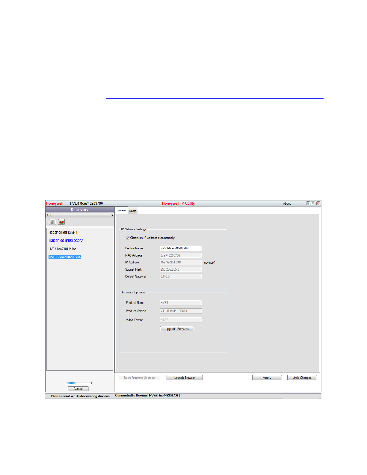
Figure 10 IP Utility
Configuring Network Parameters
If you do not know the IP address of the encoder, and this is not the first time you are using the encoder, then you can
use IP Utility or the Serial port tools to find the encoder’s IP address, and to configure the IP address or other network
parameters. We recommend that you change the default IP address for the first use.
Note For the first-time user, the default user name is admin, and the default password
is 1234. The default IP address is 192.168.0.250.
www.honeywell.com/security
Page 15

| 21
Searching for Online Devices
Automatically Searching for Online Devices
After you log on to the IP Utility, the devices on the network are automatically discovered and listed in the Discovery
pane. After the initial discovery, auto-refresh continues to discover newly added network devices.
Figure 11 Found Devices
Note Found devices will appear automatically 15 seconds after they go online. They
will disappear from the list 45 seconds after they go offline.
Manually Searching for Online Devices
Click the Refresh button to manually refresh the Online Device list. The newly discovered devices will be added
to the list.
800-15611V2 - A - 10/2013
Page 16
22 | HVE1/HVE4/HVE8 Encoders Getting Started Guide
Note You can click Up or Down buttons on each column heading to reorder the
information. Click >> to expand the device table, and to hide the network
parameter panel on the right side. Click << to show the network parameter
panel.
Modifying Network Parameters
1. Click to select a connected device from the device list the device. The network parameters for the selected device
will appear in the Modify Network Parameters panel on the right side.
2. Configure the network settings.
• Automatically – Click to select Obtain an IP Address automatically, enter the Device Name, then click Apply.
The network settings are automatically assigned from the network server.
• Manually – Click to deselect Obtain an IP Address automatically, then enter the Device Name, IP Address,
Subnet Mask, and Gateway. Then click Apply.
Figure 12 Editing Network Parameters in the Modify Network Parameters Window
www.honeywell.com/security
Page 17

Note Check the IP network settings before clicking Apply. Incorrect values might cause
a failure when connecting the tool to the device.
Note Contact your network administrator if you have any network-related issues or
questions about your network.
Connecting to an Online IP Device
1. Connect to your IP device by double-clicking it in the Discover pane, or by selecting it and clicking .
The name for the connected device turns bold and blue, and the Launch Browser button becomes active.
2. Click Launch Browser. The Honeywell IP Utility login window opens.
| 23
Figure 13 Honeywell IP Utility Window
Accessing an HVE Encoder Through a Web Browser
The HVE encoders can be accessed through a Web browser for configuration and operation.
Table 8 Supported Web Browsers
Microsoft Internet Explorer 6, 7, 8, 9
Mozilla Firefox 3.5 and above
800-15611V2 - A - 10/2013
Page 18

24 | HVE1/HVE4/HVE8 Encoders Getting Started Guide
Table 8 Supported Web Browsers
Google Chrome 8 and above
Apple Safari 5.0.2 and above
Windows XP SP1 and above (32-bit)
1. Open the web browser.
2. Enter the encoder’s IP address (default: 192.168.0.250), and then press Enter on your keyboard.
The login window appears.
Note When the HTTPS feature is enabled, the system uses the HTTPS login mode
(https://192.168.0.250) by default when you enter the IP address. You can also
enter http://IP address/index.asp (for example, http://192.168.0.250/index.asp)
if you want to use the HTTP mode to log into the device.
Figure 14 Login Window
3. Enter the user name (default: admin) and password (default: 1234) to log into the system.
Starting Live View
1. In the Live View window, click to select a playing window.
2. Double-click a camera from the device list to start Live View.
www.honeywell.com/security
Page 19

Figure 15 Live View Window
3. Click to start Live View for all of the cameras in the device list.
| 25
Table 9 Controls on the Live View Window
Icon Function
Select the viewing window division.
Start/stop live view.
Capture pictures in the live view mode.
Manually start/stop recording.
Enable PTZ control (must be supported by the connected camera)
Previous/next page.
Audio on/off.
Start/stop two-way audio.
Note Before using two-way audio or recording with audio, please configure the Stream
Type to Video & Audio under Remote ConfigurationCamera
SettingsVideo Settings.
Opening and Closing Full-Screen Mode
You can double-click on the live video to switch to the full-screen view mode. To switch back to the normal mode,
double-click on the live video again.
800-15611V2 - A - 10/2013
Page 20

26 | HVE1/HVE4/HVE8 Encoders Getting Started Guide
Operating PTZ Control
Before you begin:
• Ensure the encoder is connected to a camera/dome which supports pan/tilt/zoom control. Connect the R+ and
R- terminals on the PTZ unit or speed dome to the RS-485 T+ and RS-485 T- terminals on the encoder.
• Ensure that the baud rate, PTZ control, and address configured in the RS-485 Settings interface (Remote
Configuration
pan/tilt unit or speed dome.
PTZ Control
In Live View mode, you can use the PTZ control buttons to control the pan/tilt/zoom of the camera lens.
There are 8 directional buttons (up, down, left, right, upper left, upper right, bottom left, bottom right) on the display
window when the mouse is located in the relative positions. Click these directional buttons to control the PTZ
movement.
Serial Port Settings 485 Serial Port) are the same as the parameters of the connected
Figure 16 PTZ Controls
Table 10 PTZ Controls
Button Function
Zoom in (+) and out (-).
Focus near (+) and far (-).
Iris open (+) and close (-).
Click to turn On/Off a light (available the connected
PTZ camera supports a light).
Click to turn On/Off the wiper (available when the
connected PTZ camera supports a wiper function).
Slide the bar to set the PTZ speed from level 1 to 7.
Recording
Before you begin:
• Ensure the encoder is connected to a HDD or a network disk.
• Ensure the HDD or network disk has been initialized for the first-time use.
The following instructions apply to Scheduled recording.
www.honeywell.com/security
Page 21

| 27
Click to Enable
Record Schedule
Click to select All
Day or Customize
Scheduled Recording
1. Click Configuration Remote Configuration Camera SettingsSchedule Settings to enter the Recording
Schedule settings interface.
2. Select a camera for configuration.
3. Check to enable Enable Record Schedule.
Figure 17 Schedule Settings Window
4. Click Edit to enter the Edit Schedule window.
5. Select a day of the week for the schedule.
6. Click to select All Day or to Customize a time period.
Figure 18 Edit Schedule Window
The customized option allows you to set the start and end times for each recording period.
800-15611V2 - A - 10/2013
Page 22

28 | HVE1/HVE4/HVE8 Encoders Getting Started Guide
Note Time periods cannot overlap. You can configure up to 8 time periods.
7. Select a Recording Type from the drop-down menu. Select from Normal, Motion, Alarm, Alarm & Motion, and
Motion Alarm.
• To copy these recording configurations to the other days of the week, click Select All, and then click Copy.
• To copy these recording configurations to select days of the week, click the selection checkbox for that day,
and then click Copy.
8. On the Schedule Settings interface, click Advanced to configure advanced recording parameters.
9. Click Save to save the above settings.
Playback
Through a Web browser, you can remotely play back the recorded video.
1. Click the Playback tab to open the playback interface.
Figure 19 Playback Tab Interface
2. Click to select a camera from the device list for playback.
3. Select the date from the calendar, and then click Search.
www.honeywell.com/security
Page 23

Figure 20 Calendar
4. Click Play to play the recorded video.
Figure 21 Recorded Video Playing in the Playback Window
| 29
Use the buttons on the playback toolbars to control playback
Figure 22 Playback Toolbars
Table 11 Playback Controls
Button Function Button Function
Select the playback
window division.
Stop playback. Slow playback
Fast forward. Play single frames.
Stop playing all channels. Capture an image
Download all video files. Start/stop clipping video files.
Audio on/off.
5. Select a time for playback.
• Click and drag the progress bar to locate the exact playback point.
Play/pause.
800-15611V2 - A - 10/2013
Page 24

30 | HVE1/HVE4/HVE8 Encoders Getting Started Guide
Figure 23 Progress Bar
OR
• Enter the time in the time selector and click to locate the playback point.
Figure 24 Time Selector
The color of the video on the progress bar indicates the type of video.
Figure 25 Playback Video Types
Log
The operation, alarm, exception, and device information can be stored in log files, which can be viewed and exported
at any time.
Before you begin:
• Ensure that the connected encoder has a HDD or a network disk. The Log function works only with an encoder
that has a HDD or a network disk.
• Ensure the HDD or network disk has been initialized for first-time use.
1. Click the Log tab.
2. Set the log search conditions to refine your search. Select the Major Type, Minor Type, Start Time, and End Time.
3. Click Search to search the log files.
The log files that meet the search conditions display on the Log window.
Figure 26 Found Log Files
www.honeywell.com/security
Page 25

Note Up to 100 log files can be displayed at a time.
Saving Log Files
Click to save the found log files to a local directory.
| 31
800-15611V2 - A - 10/2013
Page 26

www.honeywell.com/security
+1 800 323 4576 (North America only)
https://www.honeywellsystems.com/ss/techsupp/index.html
Document 800-15611V2 – Rev A – 10/2013
© 2013 Honeywell International Inc. All rights reserved. No part of this publication may be reproduced by any means without written
permission from Honeywell. The information in this publication is believed to be accurate in all respects. However, Honeywell cannot
assume responsibility for any consequences resulting from the use thereof. The information contained herein is subject to change
without notice. Revisions or new editions to this publication may be issued to incorporate such changes.
 Loading...