

Page 1

Operation & Programming Manual
TM
ScanDome
HSDC-251N/P, HSDC-231N/P
Please read this manual thoroughly before use and keep it handy for future reference.
Rev.060210
llI Dome Camera
Page 2

Warnings and Cautions
OR MOISTURE. DO NOT INSERT ANY METALLIC OBJECTS THROUGH THE VENTILATION GRILLS OR
EXPLANATION OF GRAPHICAL SYMBOLS
The lightning flash with arrowhead symbol, within an equilateral triangle, is intended to
alert the user to the presence of uninsulated "dangerous voltage" within the product's
The exclamation point within an equilateral triangle is intended to alert the user to the
WARNING
TO REDUCE THE RISK OF FIRE OR ELECTRIC SHOCK, DO NOT EXPOSE THIS PRODUCT TO RAIN
OTHER OPENINGS ON THE EQUIPMENT.
CAUTION
enclosure that may be of sufficient magnitude to constitute a risk of electric shock to
persons.
presence of important operating and maintenance (servicing) instruction in the literature
accompanying the product.
2
Page 3

FCC COMPLIANCE
CE COMPL
IANCE STATEMENT
FCC INFORMATION: THIS EQUIPMENT HAS BEEN TESTED AND FOUND TO
COMPLY WITH THE LIMITS FOR A CLASS A DIGITAL DEVICE, PURSUANT TO
PART 15 OF THE FCC RULES. THESE LIMITS ARE DESIGNED TO PROVIDE
REASONABLE PROTECTION AGAINST HARMFUL INTERFERENCE WHEN
THE EQUIPMENT IS OPERATED IN A COMMERCIAL ENVIRONMENT. THIS
EQUIPMENT GENERATES, USES, AND CAN RADIATE RADIO FREQUENCY
ENERGY AND IF NOT INSTALLED AND USED IN ACCORDANCE WITH THE
INSTRUCTION MANUAL, MAY CAUSE HARMFUL INTERFERENCE TO RADIO
COMMUNICATIONS. OPERATION OF THIS EQUIPMENT IN A RESIDENTIAL
AREA IS LIKELY TO CAUSE HARMFUL INTERFERENCE IN WHICH CASE THE
USER WILL BE REQUIRED TO CORRECT THE INTERFERENCE AT HIS OWN
EXPENSE.
CAUTION: CHANGES OR MODIFICATIONS NOT EXPRESSLY APPROVED BY
THE PARTY RESPONSIBLE FOR COMPLIANCE COULD VOID THE USER'S
AUTHORITY TO OPERATE THE EQUIPMENT.
THIS CLASS A DIGITAL APPARATUS COMPLIES WITH CANADIAN ICES-003.
CET APPAREIL NUMÉRIQUE DE LA CLASSE A EST CONFORME À LA NORME
NMB-003 DU CANADA.
WARNING
THIS IS A CLASS A PRODUCT. IN A DOMESTIC ENVIRONMENT THIS
PRODUCT MAY CAUSE RADIO INTERFERENCE IN WHICH CASE THE USER
MAY BE REQUIRED TO TAKE ADEQUATE MEASURES.
3
Page 4

IMPORTANT SAFEGUARDS
1. Read these instructions.
2. Keep these instructions.
3. Heed all warnings.
4. Follow all instructions.
5. Do not use this apparatus near water.
6. Clean only with dry cloth.
7. Do not block any ventilation openings. Install in accordance with the
manufacturer's instructions.
8. Do not install near any heat sources such as radiators, heat
registers, stoves, or other apparatus (including amplifiers) that
produce heat.
9. Do not defeat the safety purpose of the polarized or grounding-type
plug. A polarized plug has two blades with one wider than the other.
A grounding type plug has two blades and a third grounding prong.
The wide blade or the third prong is provided for your safety. If the
provided plug does not fit into your outlet, consult an electrician for
replacement of the obsolete outlet.
10. Protect the power cord from being walked on or pinched particularly
at plugs, convenience receptacles, and the point where they exit from
the apparatus.
11. Only use attachments/accessories specified by the manufacturer.
12. Unplug this apparatus during lightning storms or when unused for
long periods of time.
13. Refer all servicing to qualified service personnel. Servicing is
required when the apparatus has been damaged in any way, such as
when the power-supply cord or plug has been damaged, liquid has
been spilled or objects have fallen into the apparatus, the apparatus
has been exposed to rain or moisture, does not operate normally, or
has been dropped.
14. CAUTION - THESE SERVICING INSTRUCTIONS ARE FOR USE
BY QUALIFIED SERVICE PERSONNEL ONLY. TO REDUCE THE
RISK OF ELECTRIC SHOCK DO NOT PERFORM ANY SERVICING
OTHER THAN THAT CONTAINED IN THE OPERATING
INSTRUCTIONS UNLESS YOU ARE QUALIFIED TO DO SO.
15. Use Certified/Listed Class 2 power supply transformer only.
4
Page 5

Table of Contents
Chapter 1 — Introduction...................................................................................................................7
1.1 Features.....................................................................................................................................................7
1.2 Typical System Configuration...............................................................................................................8
Chapter 2 — Installation and Configuration....................................................................................9
2.1 Unpacking the box...................................................................................................................................9
2.2 Basic Configuration of ScanDome Camera System...........................................................................9
2.3 Principle of Termination......................................................................................................................10
2.4 Dome Camera Address (ID)................................................................................................................11
2.5 Setting Protocols....................................................................................................................................12
2.6 Connections............................................................................................................................................12
2.7 Mounting the Dome Camera...............................................................................................................14
2.8 Power on and Boot-up Sequence........................................................................................................14
Chapter 3 — Program and Operation..............................................................................................16
3.1 FUNCTION............................................................................................................................................16
3.1.1 HOME FUNCTION (MENU =>FUNCTION => HOME FUNCTION).....................................................17
3.1.2 PRESET ( MENU => FUNCTION => PRESET Short Cut :PRST ).........................................................18
3.1.3 PATTERN (MENU => FUNCTION => PATTERN or Shortcut: PTRN).................................................19
3.1.4 SCAN ( MENU => FUNCTION => SCAN or Shortcut: SCAN)................................................................21
3.1.5 TOUR (or MENU => FUNCTION => TOUR, Short Cut: TOUR ).............................................................22
3.2 ALARM ( MENU => ALARM)...........................................................................................................23
3.3 SCREEN.................................................................................................................................................25
3.3.1 LANGUAGE( MENU => SCREEN => LANGUAGE)................................................................................25
3.3.2 PRIVACY ZONE ( MENU => SCREEN => PRIVACY ZONE)................................................................26
3.3.3 NORTH DIRECTION ( MENU => SCREEN => NORTH DIRECTION).................................................27
3.3.4 ZONE TITLE ( MENU => SCREEN => ZONE TITLE).............................................................................27
3.3.5 CAMERA TITLE ( MENU => SCREEN => CAMERA TITLE)................................................................28
3.4 CAMERA ( MENU => CAMERA)....................................................................................................29
5
Page 6

3.4.1 FOCUS CONTROL( MENU => CAMERA => FOCUS CONTROL)........................................................29
3.4.2 WB (white balance) ( MENU => CAMERA => WB CONTROL)..............................................................29
3.4.3 AE CONTROL ( MENU => CAMERA => AE CONTROL).....................................................................30
3.4.4 BLC/BMB SETUP ( MENU è CAMERA èBLC/BMB SETUP)..........................................................30
3.4.5 SHARPNESS CONTROL ( MENU => CAMERA =>SHAPENESS)........................................................31
3.4.6 DIGITAL ZOOM ( MENU => CAMERA =>DIGITAL ZOOM)................................................................31
3.4.7 NIGHT SHOT MENU ( MENU => CAMERA =>NIGHT SHOT).............................................................31
3.4.8 CAMERA DEFAULT ( MENU => CAMERA =>CAMERA DEFAULT).................................................32
3.5 SETUP ( MENU => SETUP)...............................................................................................................32
3.5.1 FLIP (MENU => SETUP => FLIP)..............................................................................................................32
3.5.2 SPEED (MENU => SETUP => SPEED)........................................................................................................32
3.5.3 PRESET FREEZE (MENU => SETUP => PRESET FREEZE)....................................................................32
3.5.4 PANNING RANGE (MENU => SETUP => PANNING RANGE)..............................................................33
3.5.5 TILT OVER ANGLE (MENU => SETUP => TILT OVER ANGLE).........................................................33
3.5.6 CALIBRATION (MENU => SETUP => CALIBRATION)..........................................................................33
3.4.7 LINE LOCK CONTROL ( MENU => CAMERA => L/L CONTROL)....................................................34
3.5.8 FACTORY DEFAULT (MENU => SETUP => FACTORY DEFAULT)...................................................34
3.5.9 ERASE DATA (MENU => SETUP => ERASE DATA)...............................................................................34
3.5.10 SYSTEM INFORMATION (MENU => SETUP => ERASE DATA)........................................................35
Appendix A — Specifications............................................................................................................36
Appendix B — Troubleshooting.......................................................................................................39
6
Page 7

Chapter 1 — Introduction
1.1 Features
The ScanDome TMIII dome camera features a high resolution ExView HAD CCD
enhanced lowlight sensitivity. User friendly, on-screen pull-down menus and short-cuts make it
easy to setup and program functions.
System information aides trouble shooting by displaying the hardware and software version of
the dome driver, baud rate, and protocol.
• Built-in 23x or 25x times optical power zoom camera.
True Night Shot function with ExView HAD and IR cut filter removal mechanism
• 248 Presets programmed with view direction, zoom, BLC, BMB.
• 4 Patterns record and play back user preference of surveillance path up to 240 sec.
*)option
imager for
• 16 Scans : 8 speed steps from slow to medium panning with smooth DiagonalScan.
• 8 Tours : Each tour consists up to 64 Preset, Pattern, Scan and other Tours.
Tour can be expanded up to 500 different functions using nested Tours.
Smooth DiagonalScan mode and programmable Individual dwell time camera functions.
(Speed, Dwell time, BLC, BMB, Focus, IRIS of the preset)
• 8 Alarm inputs with 0~8 priority / 2 Auxiliary outputs programmable NC & NO.
• 8 Privacy Zones : Video off or up to 8 masked blocks and 8 mask color selectable
• 64 steps of variable speed from 0.1°/sec to 90°/sec.
Max manual speed 360°/sec with Turbo key pressed, Preset speed is 380°/sec.
Minimum adjustable angle is 0.0375° with SingleStep move function.
• Programmable user preferences of speed (Slow, Medium, Fast).
• Addressable up to 999 camera IDs (Extendable up to 3999 in factory mode).
• Built-in RS-485/422 receiver driver.
• On-site software upgrade and upload/download of programmed data into the KBD/Dome.
• Built-in power-line surge protection and lightning protection.
• Capable of fail-safe Hot Swap.
• Optional Tinted Bubble, Indoor & Outdoor pendant housing with heater & blower, Indoor Flush
Mount, Parapet mount & Roof Top mount.
7
Page 8

1.2 Typical System Configuration
Additional ScanDome joystick controllers and a variety of external switching devices such as
multiplexers(MUXes) and Digital Video Recorders (DVRs) may be incorporated to accommodate
the needs from the small to large surveillance/security system. Figure 1 illustrates a small
sample installation.
Figure 1 – Typical System Configuration
8
Page 9

Chapter 2 — Installation and Configuration
2.1 Unpacking the box
The package contains the following.
Quantity Component
1 ScanDomeTMIII (Dome Camera)
1 Instruction Manual (this document)
3 Assembly Screws for Attaching ScanDome
3 Plastic Anchor
1 3-Pin Connector
1 4-Pin Connector
2 8-Pin Cable Assembly
3 3-Bolt Spacer(Use for HSGN-502 and HSG-502F only)
2.2 Basic Configuration of ScanDome Camera System.
POWER
STP AWG # 22
AC 24V
BNC MONITOR
TERMINATION
VIDEO
TXB(DOME1 -)
TXA(DOME1+)
TXB
TXA
RXB
RXA
RX-
RX+
TX-
TX+
GND
ON
COM2
NC2
NO2
GND
SW2
AL5
AL6
AL7
J2 J1
RS-422
FULL DUPLEX MODE
RXA(RX+)
RXB(RX -)
TXB(TX-)
TXA(TX+)
TXA
TXB
RXA
RXB
POWER
AC 24V
FGND
AC-
AC+
FG
24V~
24V~
SW1
J5J7
COM1
NC1
NO1
GND
AL1
AL2
AL3
AL4AL8
RS-485 or
RS-422 HALF DUPLEX MODE
TXA(TX+)
TXB(TX-)
TXB
TXA
RXB
RXA
Figure 2 – Basic installation diagram
9
Page 10

Address(ID)
Address(I
D)
The dome camera must be installed by qualified service personnel. Before installing the dome
camera system this instruction manual must be read thoroughly and understood fully. Dome
cameras must be set up properly before starting the installation. This involves properly setting
configuration switches. Figure 3 shows the location of these switches.
0
0
0
1
1
1
9
9
9
2
2
2
8
8
8
3
3
3
7
7
7
4
4
4
6
6
6
5
5
5
Selection Switches
Selection Switches
S1 S2 S3
S6S5S4
Protocol Selection Switches
Figure 3– Layout of Switches
2.3 Principle of Termination
Every device which is connected at the end of the communication data line must be terminated
by either DIP switch setting or appropriate devices such as a termination jumper to prevent
potential control signal errors.
See Figure 4 for termination switch settings and Figure 5 for examples of devices requiring
termination. Note : Total length of the cable for communication should not exceed 1.2Km.
SW2 1 2
ON
SW2
1 2
Terminated ON ON
Not terminated OFF OFF
Figure 4– Setting Dome Camera Termination
10
Page 11

S1:Dome1 port Termination ON
SW2:Termination ON
S1:Dome1 port Termination ON
SW2:Termination ON SW2:Termination ON
SW2:Termination ON
S1:Dome1 port Termination ON
SW2:Termination ON
DVR Termination ON
DVR Termination ON
SW2:Termination ON
S4:DVR port Termination ON
DVR Termination ON
SW2:Termination ON
DVR Termination ON
SW2:Termination ON
S1:Dome1 port Termination ON
SW2:Termination ON
S3:Dome2 port Termination ON
SW2:Termination ON
SW2:Termination ON
TERMINATION ON
Figure 5- Termination Diagram
2.4 Dome Camera Address (ID)
Each dome camera must have a unique address (ID). Identical IDs on the same line may
damage the control circuit caused by an electrical short. When installing multiple dome cameras
or a DVR, it is recommended that the dome camera IDs be identical to the camera port of the
DVR.
Cam Port 1 = Dome ID1, Cam Port 2 = Dome ID 2 … Cam Port 16 = Dome ID 16.
If more than 16 dome cameras are installed using two or more DVRs the following formula is
useful to determine the Dome ID: ID =16x(n-1)+m ( where n= number of DVR, m=Camera Port)
11
Page 12
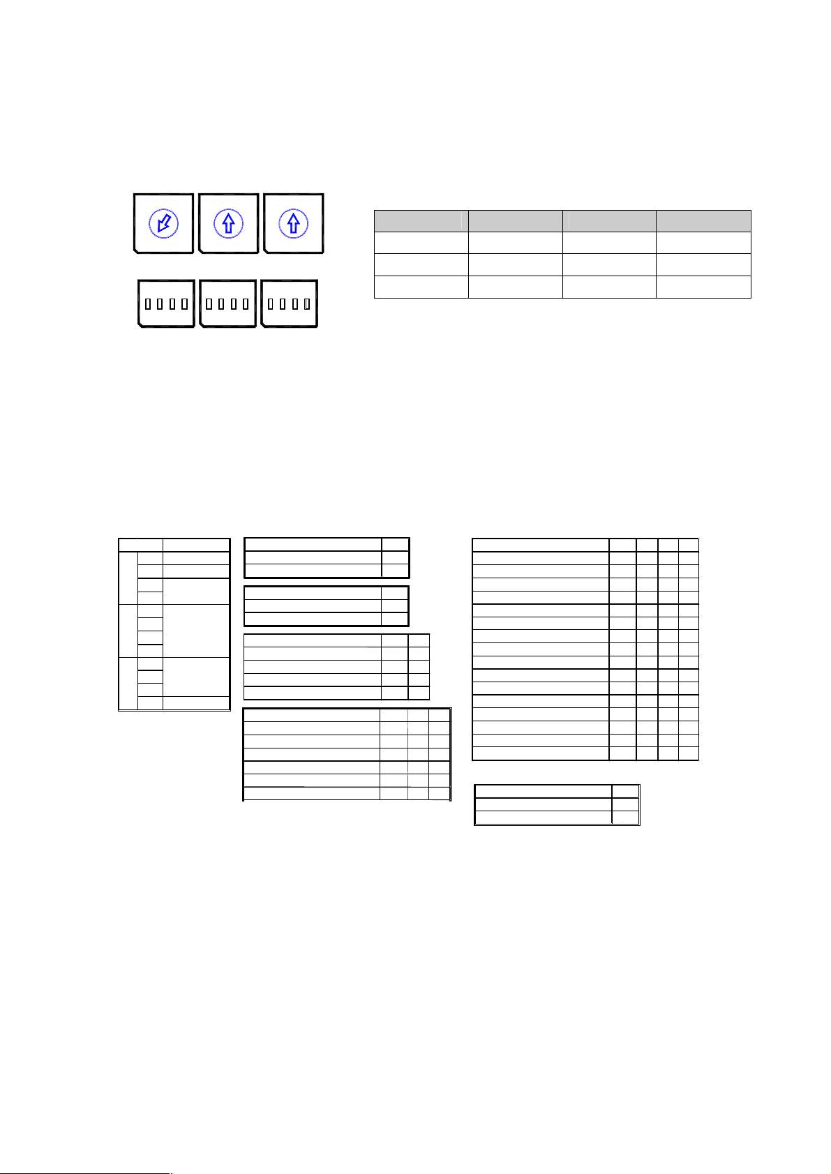
Refer to Figures 6 for setting the dome camera address (ID) and protocol selection.
OFF
ON
D3 D4
On
On On
D5 D6 D7 D8
S2
PD On
VN
SN On On On
DC
On On On On
D9
On
On
S1
456
3
2
7
8
9
1
0
S4
on on on
S2
5
6
4
3
2
7
8
9
1
0
S5
S3
5
6
4
3
2
9
1
0
S6
7
8
DOME ID
S3 S2 S1
1 0 0 1
.
999
. . .
9 9 9
Figure 6– Setting Dome Camera Address (ID) and Protocol
2.5 Setting Protocols
A ScanDome camera is capable of negotiating with multiple protocols if the communication
speed is matched (same baud rate i.e., 9600 bps). See Figure 7 for the appropriate protocol
switch settings.
Note : Consult service personnel if a dome camera is installed with a device other than a
ScanDome Controller.
Dip s/w
S4
S5
S6
Function
D1 VIDEO
D2 COMM.
D3
Camera
D4
D5
D6
Protocol
D7
D8
D9
Baud rate
D10
D11
D12Extended ID
VIDEO D1
NTSC Off
PAL On
COMMUNICATION D2
RS-422 On
RS-485 Off
Camera
Default
RESERVED
RESERVED
RESERVED
Baud rate
2400 bps
4800 bps
9600 bps
19200 bps
38400 bps
57600 bps
2.6 Connections
• How to Connect RS485/422
The dome camera has a built-in RS-485/422 receiver so that it can be controlled
remotely by an external control device such as a joystick controller or DVR.
Protocol
S2/E,PL,ER,PH(No)
S2/E,PL,ER,PH(Even) On Off Off Off
PL
RESERVED
Off Off
Off
Off On
D10 D11
Off Off Off
Off Off On
Off On Off
Off On On
Off Off
Off On
RESERVED
RESERVED
RESERVED
RESERVED
VCL
KD6
Factory Default
Extended Dome ID D12
0~999 On
1000~3999 Off
Figure 7– Protocol Selection tables
Off Off Off Off
Off On Off Off
On On Off Off
Off Off On Off
Off On Off
Off On On Off
Off
Off Off Off On
On Off Off On
Off On Off On
On On Off On
Off Off On On
On Off On On
Off On On On
RS-485: Connect the TXA(Tx+) and TXB(Tx-) of the RS485 control devices ( KDB,
DVR…)to RX+, RX- of the dome camera.
12
Page 13

RS-422: Connect TXA(Tx+) and TXB(Tx-) of the control device to RX+, RX- and
TX+, TX- of the dome camera respectively. You need to select RS-422 mode at S4.
RS-485 does not allow for a star connection layout. A splitter is required if a star
connection layout is desired. RS-485 guarantees 1.2 Km of data line routing. A
repeater is recommended to extend over 1.2 Km.
• Connecting Video output
See page 9 Figure 2 – Basic installation diagram
• Connecting Alarms
AL1 to 8 (Alarm In)
Magnetic, PIR or other external sensor devices can be used to signal the dome
camera reacting to an event.
ㅡㅡ See Chapter 3 — Program and Operation for configuring alarm input.
TX+
GND
FG
RX-
RX+
TX-
24V~
24V~
J5J7
SW1
SW2
COM2
NC2
NO2
GND
AL5
AL6
AL7
J2 J1
COM1
NC1
NO1
GND
AL1
AL2
AL3
AL4AL8
Pin configuration of the supplied alarm cable JP4 and JP2
GND (Ground)
NOTE: All the connectors marked GND are common.
Connect the ground of the Alarm input and/or alarm output to the GND connector.
NO / NC (Normally Opened or Normally Closed dry contact relay output)
The dome camera can activate external devices such as buzzers or lights using dry
contact relays. Connect the device to the NO(NC) (Alarm Out) and COM (Common)
connectors. See Chapter 3 — Program and Operation for configuring alarm output.
• Connecting the Power
Connect AC 24V 1000mA power to the dome camera.
Use certified / Listed Class 2 power supply transformer only.
13
Page 14

2.7 Mounting the Dome Camera
Lock CW
Unlock CCW
Once all DIP switches are set appropriately and all external connections are made, the dome
camera can be mounted.
The ScanDome camera is designed to mount on a structural surface supporting loads up to 5
Kg. See Figure 8.
c
o
c
o
Fasten Screw
Figure 8 – Example of a ceiling mounted installation
2.8 Power on and Boot-up Sequence
When the power is applied to the dome camera, it will start a boot-up sequence. When boot-up
is done, the following information is displayed on the monitor screen.
14
Page 15

:0001
Preset No.
Preset Title
Or Area Title
Information
Alarm Display
Pan & Tilt Angle
RAM TEST
CHECK NO. : OK!
CHECK AAAA : OK!
CHECK 5555 : OK!
SCANDOMEIII Vx.xxx
CAMERA TYPE xxxx
WAIT DOME SETTING.
INIT TILT ORIGIN SET OK
INIT PAN ORIGIN SET OK
INIT CAMERA SET OK
On Screen Display in normal control mode
001 PRESET W→
EMPTY DATA !
ALARM:1
360.0,090.0 DOME NO.
Compass Direction
Dome Camera Title
Dome Camera ID
15
Page 16

Chapter 3 — Program and Operation
Dome Camera Selection
Before you start programming or operating a dome camera, you should make the dome camera
be under control of the joystick controller. In other words, the dome camera that you want to
effect changes must be currently selected.
Example: Pressing 1 , 6 and CAM key sequentially will select dome camera 16. The selected
dome camera ID will be displayed on the monitor.
Principle of joystick usage in the programming (editing) mode
Button or Joystick movement in menu Function
Joystick left or right
Go into the sub-menu items.
Execute the command(exit)
Change value.
Navigate through the menu items.
Joystick up or down
Joystick down
Zoom handle twist
SHFT + Joystick
ESC
Home or Off button Delete value or name of the field.
Navigate through the menu items.
Finish editing title.
Change value.(Increase / Decrease)
Enter editing title mode.
PTZ control mode.
Escape from the menu without change.
3.1 FUNCTION
Pressing the MENU button on the keyboard controller, the following On-screen MAIN MENU will
be shown on your monitor screen.
MAIN MENU
FUNCTION
ALARM
SCREEN
CAMERA
SETUP
EXIT
16
Page 17

Locate the cursor on the FUNCTION item and then push the joystick to the right to enter
FUNCTION menu.
FUNCTION
HOME FUNCTION
PRESET
PATTERN
SCAN
TOUR
EXIT
3.1.1 HOME FUNCTION (MENU =>FUNCTION => HOME FUNCTION)
After HOME FUNCTION item has been selected, follow the directions below to set HOME
function.
FUNCTION : Tour/ Preset/ Pattern/ Scan
NUMBER : - - TIME : 10~240 Seconds
OPERATION : ENABLE/ DISABLE
The HOME function invokes predefined functions such as Preset, Tour, Pattern, or Scan
function after the keyboard controller has been idle for a programmed time.
Follow the steps below to program the Home function:
1. Select the camera number by pressing No. and CAM
HOME FUNCTION
FUNCTION : NONE
NUMBER : --TIME : 240 SEC
OPERATION : DISABLE
SAVE AND EXIT
2. Press MENU to display the main menu on the monitor.
3. Push the Joystick to the right on “FUNCTIONS”.
4. Enter Home Function menu by pushing the Joystick to the right.
5. Push the Joystick to the right/ left (or twist CCW/CW) to scroll Tour, Pattern, Auto Scan
and Preset functions.
6. Select Function Number by pushing the Joystick down, and twist the Joystick to the
CCW/CW (or push right/left). The executable function number will be scrolled. If selected
function is not programmed, it won’t change. Go to setup function first.
17
Page 18

7. Pushing the Joystick down and twist the Joystick to CCW/CW (or push the stick to
right/left) to set waiting time.
8. Locate the cursor on OPERATION option by pushing the Joystick down. Choose
operation status Enable or Disable by pushing the Joystick to the right or to the left (or
twist CCW/CW).
3.1.2 PRESET ( MENU => FUNCTION => PRESET Short Cut :PRST )
Preset memorizes pan, tilt, zoom, focus and iris settings. Once programmed, pressing
combination of 0 ~9 numbers and a Preset button on your controller automatically calls up the
preset position. Presets may be assigned to alarm actions or as the “home” position for the
dome camera.
Locate the cursor on the PRESET item and then push the joystick to the right to enter PRESET
menu.
FUNCTION
HOME FUNCTION
PRESET
PATTERN
SCAN
TOUR
EXIT
There are 31 pages of preset programming menu. Each page can hold 8 presets. Locate the
cursor on “PREV NEXT”, preset menu pages can be scrolled by pushing the Joystick to
the Left or Right on the “PREV NEXT”.
PRESET 01/31
NO. F I B TITLE
001 A A F xxxxxxxxxxxxxxxx
002 M M O ---------------003 - - - ---------------004 - - - ---------------005 - - - ---------------006 - - - ---------------007 - - - ---------------008 - - - ---------------PREV NEXT
SAVE AND EXIT
F : Focus I : IRIS B : BLC
X : 16 digit of preset title
- : not defined
█ : Current cursor position
F : A(Auto Tracking)/M(Manual Tracking)
I : A(Auto Iris)/M(Manual Iris)
B : F(BLC OFF)/O(BLC ON)/A(Auto BLC)/B(BMB)
18
Page 19

Follow the steps below to program the Preset positions.
1. Select the camera number by pressing 0 ~9 and CAM.
2. Simply press PRST button to enter preset menu. ( MENU => FUNCTION => PRESET)
3. Select the empty preset location to be programmed using the Joystick up/down. If
selected location is not empty, pressing PRST button will show your predefined position.
4. After selecting an empty position, press and hold SHFT/PGM then use the Joystick to
control the direction of the camera and lens.(Or twist zoom handle or hit zoom button to
start PTZ control for view selection.)
5. After aiming the camera (view direction and lens control) at specific position, release
SHFT/PGM button(or hit the focus button). The selected location No. field will be filled with
“A A F”. Push the joystick to the right to select each Focus/ Iris /BLC mode using zoom
handle.
6. Move the cursor to the title field to edit/enter the title. Rotate the handle CW and CCW or
press Tele or Wide button to scroll through the alphanumeric characters. Push the
handle to right or left to select next or previous digit.
7. To finish entering the title, push the Joystick up/downward.
8. Locate the cursor on “PREV NEXT” item to select the previous/next page of presets,
scroll the page by pushing the Joystick to the Left on “PREV NEXT”.
9. Repeat steps 2 through 8 for each additional preset position.
10. Select Save and Exit by pushing the Joystick to the right. Press ESC to exit the Preset
menu without saving.
NOTE: Press the Home or OFF button at programmed position to delete a programmed preset view.
Shortcut of Preset Program.
Select direction of the camera, zoom and focus to be programmed, then press No. (1~248), and
then press SHFT, PRST subsequently. The current view will be stored to the selected preset
number if position is empty. If selected preset number is not empty, “PRESET EXISTING”
message will be displayed on the monitor and you will be prompted to overwrite.
Example: 1, 0 + PGM + PRST will memorize current view as preset No. 10. In this case, focus
and Iris mode will be memorized as auto and dwell time will be set to 3 sec.
3.1.3 PATTERN (MENU => FUNCTION => PATTERN or Shortcut: PTRN)
The Pattern function stores user’s control of the selected dome camera for up to 240 seconds. 4
patterns can be stored in 240 seconds of total recording space. Stored pattern is played back by
pressing No.+ PTRN buttons subsequently.
19
Page 20

PATTERN SETUP
NO. TITLE SEC
01 : xxxxxxxxxxxxxxxx 000
02 : xxxxxxxxxxxxxxxx 041
03 : xxxxxxxxxxxxxxxx 010
04 : xxxxxxxxxxxxxxxx 020
TOTAL :
071
SAVE AND EXIT
Follow the steps below to program the Pattern:
1. Press MENU key to display the main menu on the monitor.
2. Simply press the PTRN key. (or MENU => FUNCTION =>PATTERN)
3. Select the empty Pattern number to be programmed by pushing the Joystick Up or Down.
If SEC column is not 000, then the selected No. of pattern is already recorded.
4. Press and hold down the SHFT/PGM key while controlling the camera direction and zoom
with the Joystick. Your controls will be automatically recorded until you release the
SHFT/PGM key. You can repeat this procedure until you are satisfied with the pattern
recorded. (Or twist zoom handle or hit zoom button to start PTZ control for view selection
and hit the Focus button to stop.)
5. Scroll down to the Save and Exit option and push the Joystick to the right to save and
exit.
6. You can title the selected Pattern by twisting the Joystick. Rotate the handle clockwise
or counterclockwise to scroll through the alphanumeric characters, push the handle to right
or left to select next or previous space.
7. Pressing ESC will not save currently recorded data and exits to the previous menu mode.
Press the HOME or OFF button at any programmed position to delete the programmed
pattern.
NOTE: If total recording time reaches 240 seconds, it will automatically stop for a moment and
start recording again. Previous data will be overwritten.
20
Page 21

3.1.4 SCAN ( MENU => FUNCTION => SCAN or Shortcut: SCAN)
The Scan function supports up to 16 programmed section of angles at 8 programmable speeds.
SPEED(MODE) : 1/ 2 / 3/ 4/ 5/ 6/ 7/ 8/ SLOW / MEDIUM
Follow the steps below to program Scans.
1. Press the SCAN key to enter Auto Scan menu directly. (or MENU => FUNCTION =>
SCAN).
SCAN MENU 01/16
SCAN 01 : AUTOSCAN01
SPEED : 1~8/SLW/MID
START : 127.1, 027.0
END : 157.7, 080.7
DIR. : CCW
SWAP : OFF
SAVE AND EXIT
1: SLOWER ↔ 8 FASTER
SLW : smooth DiagonalScan in slowest speed
MID : smooth DiagonalScan in medium speed
DiagonalScan shows moving path from start point to end point including
tilt and zoom simultaneously.
2. Select an Auto Scan number by pushing the Joystick left or right.
3. Twist the Joystick to enter the title by scrolling through the alphanumeric characters
and pushing the handle to the right or left to move to the next space. Press ENTR key or
push the Joystick down to finish title mode.
4. Push the Joystick downward to select “SPEED” and set the speed by twisting the
Joystick clockwise or counterclockwise or moving the Joystick left/ right to select
the auto scan speed.
5. When finish entering the title, select “START ANGLE” with the Joystick. Hold down the
SHFT/PGM key while selecting the start position using the Joystick. Current panning
position will be displayed. Release SHFT/PGM key to complete the selection of the start
position. (Or twist zoom handle or hit zoom button to start PTZ control for view selection
and hit the Focus button to stop.)
6. Push the Joystick downward to select “END ANGLE.” Hold down the SHFT/PGM key
while moving the Joystick to select the end position. The end position angle should be
larger than start position. Release the SHFT/PGM key to complete the selection of the end
position. (Or twist zoom handle or hit zoom button to start PTZ control for view selection
and hit the Focus button to stop.)
7. Push the Joystick downward to select “DIR.” Set the scan direction by moving the
Joystick left and right to select the auto scan direction.(CW or CCW)
21
Page 22

8. Push the Joystick downward to select “SWAP” and set the swap by moving the
Joystick left and right to select the swap ON or OFF.
9. Select Save and Exit by pushing the Joystick to the right. Press ESC to exit the
program without saving.
NOTE: Press 17 + SCAN to automatically calls up the auto-pan function.
3.1.5 TOUR (or MENU => FUNCTION => TOUR, Short Cut: TOUR)
There are 8 programmable Tours. Each Tour consists of up to 8 Preset positions, Patterns,
Scans or other Tours. Using second-level Tours, it can be expanded to over 56 functions in a
single Tour. However tours second level Tours will be ignored when called by a Tours. This can
be best illustrated by the following example:
If Tour 01 : Preset 02, Preset 03,Tour 02, Tour 03
Tour 02 : Preset 05, Preset 06, Tour 04, Preset 05
Tour 03 : Preset 07, Pattern 01
Tour 04 : Preset 08. Preset 05, Pattern 01
Tour1 executes as follows:
Preset 02 è Preset 03 è Preset 05 è Preset 06 è Preset 05 è Preset 07 è Pattern
01 è ... (Repeat) ---Tour 04 in Tour 02 will be skipped in Tour 01
Tour 02 executes as follows:
Preset 05 è Preset 06 è Preset 08 è Preset 05 è Pattern 01 èPreset 05 …
Repeat (Tour4 is still valid if called directly from Tour2.)
TOUR 01:xxxxxxxxxxxxxxxx 01/08
FUNC NO S DW TITLE
PRST 248 S 99 ---------------PTRN 004 S 99 ---------------SCAN 016 S 99 ---------------TOUR 008 S 99 ----------------
---- --- - -- ----------------
---- --- - -- ----------------
---- --- - -- ----------------
---- --- - -- ----------------
PREV NEXT
SAVE AND EXIT
xxxxx : 16 digits of title for tour label
- - - : blank preset position
Speed : Fast (Normal)/ Slow V. Scan/ Medium V. Scan
DWell : 03-99 Sec
PRST : Preset 1~248
PTRN : PATTERN 1~4
SCAN : SCAN 1~16
TOUR : TOUR 2~8
22
Page 23

Follow the steps below to program the Tours:
1. Press MENU => FUNCTION => TOUR, Short Cut: TOUR MENU to display the main menu
on the monitor. No. + SHFT+TOUR will open directly Tour No.
2. Choose an empty location of function by pushing the Joystick up or down.
3. Stored Preset view can be recalled by pressing Prst button, the camera will move to the
stored Preset view.
4. To place predefined functions as a Tour, press the function buttons (such as Tour, Ptrn,
or Scan ,Prst ). Then select function No. by twisting the Zoom handle. (Programmed
function No. will be scrolled). To remove functions from the Tour, press the HOME or Off
button, blank position mark (- - -) will be displayed. You can overwrite the programmed
position.
5. Repeat Step 2 through 4 for each desired position. Each title will be displayed on top of the
line.
6. Up to 8 Presets, Tours, Patterns Scans can be selected for a Tour. You can expand the
Tour sequence by calling other programmed tours. Push the Joystick handle to right or
left while the cursor is on the top of the line (TOUR 01) to select another page of the Tour
menu. (TOUR 01)
7. You can enter a title for the selected Tour by twisting the Joystick while the cursor is on
the top of the line (TOUR 01). Rotate the handle clockwise or counterclockwise to scroll
through the alphanumeric characters. Push the handle to the right or left to select the next
or previous digit.
8. Select Save and Exit by pushing the Joystick to the right. Press ESC to exit the program
without saving.
NOTE: All functions should be programmed before being referred to in the tour menu. Otherwise
functions won’t be selectable by item 4 in the procedure.
3.2 ALARM ( MENU => ALARM)
MAIN MENU
FUNCTION
ALARM
SCREEN
CAMERA
SETUP
EXIT
Locate the cursor on ALARM item in the main menu and push the joystick to the right for
ALARM programming of the camera.
23
Page 24

NO : Alarm input number
FUNC : Priority 1~8 calls Preset(xxx),
Priority 0 supports dedicated functions like a Pattern(Pxx), Tour(Txx), Scan(Sxx).
PRI : Lower No. has higher priority, Equal priority alarms will be serviced repeatedly.
IN : NO/NC - normally open /Closed, OFF - ignore
OUT : OUT1~OUT2 - Relay out 1,2 OFF - No output.
HLD : Alarm will be held for programmed time (01 to 99 seconds)
LATCH : ON - Shows all alarms including past alarm, OFF - Shows activated alarms only.
There are 9 levels of priority. 0 : Highest priority supports repeated/dedicated functions
like a Pattern(Pxx), Tour(Txx), Scan(Sxx). 1~8: Same level of alarm calls presets one
after the other.
Ex) Alarm 01 calls Pattern 01, After alarm 01 is released alarm 02, 03 will call preset 48
and preset 01
1. Press Menu to display the main menu on the monitor. Select the Alarm option by pushing
the Joystick up or down and push to right to enter the detail menu.
ALARM SETUP
NO FUN PRI IN OUT HLD LATCH
01 P01 0 OFF OFF 001 OFF
02 048 4 OFF OFF 001 OFF
03 001 4 OFF OFF 001 OFF
04 --- 3 OFF OFF 001 OFF
05 --- 3 OFF OFF 001 OFF
06 --- 3 OFF OFF 001 OFF
07 --- 3 OFF OFF 001 OFF
08 --- 3 OFF OFF 001 OFF
SAVE AND EXIT
2. Select the alarm input number by pushing the Joystick up or down and select the
column you wish to setup. Selected position will be highlighted.
3. Select the Preset, Status of Input (NC/NO/OFF), and Output (OUT1~2/OFF) by pushing
the Joystick to the right or to the left.
4. To increase or decrease the preset number or to change the status or output number, twist
the Joystick clockwise or counterclockwise. In case of preset, programmed preset
number will be scrolled.
5. Locate the cursor on Save and exit and push the Joystick to the Save and exit.
Press ESC to exit the program without saving.
24
Page 25

3.3 SCREEN
Pressing the MENU button on the keyboard controller, the following On-screen MAIN MENU will
be shown on your monitor screen.
Locate the cursor on the SCREEN item and then push the joystick to the right to enter SCREEN
menu.
MAIN MENU
FUNCTION
ALARM
SCREEN
CAMERA
SETUP
EXIT
SCREEN MENU
LANGUAGE
PRIVACY ZONE
NORTH DIRECTION
ZONE TITLE
CAMERA TITLE
EXIT
3.3.1 LANGUAGE( MENU => SCREEN => LANGUAGE)
Push the joystick handle to the right to select LANGUAGE options.
Preferred language will be scrolled when you push the joystick to the right on LANGUAGE
ENGLISH.
LANGUAGE SETUP
LANGUAGE ENGLISH
SAVE AND EXIT
25
Page 26

3.3.2 PRIVACY ZONE ( MENU => SCREEN => PRIVACY ZONE)
Locate the cursor on the PRIVACY ZONE item and then push the joystick to the right to enter
the menu.
This function disables the viewing of restricted areas for privacy reasons. Mask up to 8
unwanted views in a camera.
1. Select the Privacy Zone option by pushing Joystick Up or Down and push to right to
enter the detail menu.
SCREEN MENU
LANGUAGE
PRIVACY ZONE
NORTH DIRECTION
ZONE TITLE
CAMERA TITLE
EXIT
PRIVACY ZONE SETUP
NO TITLE METHOD
01 xxxxxxxxxxxxxxxx ON BLOCK
02 xxxxxxxxxxxxxxxx OFF V.OFF
03 NONE ---04 NONE ---05 NONE ---06 NONE ---06 NONE ---08 NONE ---COLOR : BLUE
SAVE AND EXIT
2. Select the privacy zone number by pushing the Joystick up or down.
3. To enter the zone name, rotate the handle clockwise or counterclockwise. You can select
alphanumeric characters by rotating the handle. Move to the next character position by
pushing the Joystick to the right. To finish entering the title, push the Joystick down or
press the ENTR key.
4. To adjust the “marked” (privacy) area, press and hold down the SHFT/PGM key and then
use the Joystick (direction and zoom) until you get desired view. Release the key, the
right column will be set to ON. (Or twist zoom handle or hit zoom button to start PTZ
control for view selection and hit the Focus button to exit from control mode.)
5. You can overwrite an existing zone. Use the Home key to delete the marked zone, or push
the Joystick to the right or left to turn the stored zone On or Off.
6. Select the mask color by pushing the Joystick left or right
26
Page 27

7. Select the Save and Exit option by pushing the Joystick up or down. Save and exit the
DISPLAY : ON
program by pushing the Joystick to the right. Press ESC to exit the program without
saving.
Press the HOME orOff button to delete programmed privacy zone.
3.3.3 NORTH DIRECTION ( MENU => SCREEN => NORTH DIRECTION)
Push the joystick handle to the right to select NORTH DIRECTION options.
1. Select DISPLAY option whether display or not.
2. Move to POSITION item to set north direction, press and down the SHFT/PGM key and
then use the Joystick (direction and zoom) until you get desired direction. Release the
key then current pan angle will be displayed on position item. (Or twist zoom handle or hit
zoom button to start PTZ control for view selection and hit the Focus button to exit from
control mode.)
NORTH DIRECTION
DISPLAY : OFF
POSITION : 000.0
SAVE AND EXIT
3.3.4 ZONE TITLE ( MENU => SCREEN => ZONE TITLE)
Enter a specific name in sectioned angle between START and END.
DISPLAY : ON/OFF zone title on the screen
1. Press MENU => SCREEN => ZONE TITLE to display zone title menu on the monitor.
2. Select the zone number by pushing the Joystick up or down. Select Start, End or number
column to be set by pushing the handle to the right or left. The selected column will be
highlighted.
ZONE TITLE 01/04
NO TITLE START END
01 WINDOW 123.4 345.6
02 ----- ----03 ----- ----04 ----- ----05 ----- ----06 ----- ----PREV NEXT
SAVE AND EXIT
27
Page 28

3. Twist the joystick handle on the No. column to enter zone title. You can select alphanumeric
characters by rotating the handle. Move to the next character by pushing the Joystick to
the right. To finish entering the title, push the Joystick down.
4. To adjust panning limit, press the SHFT/PGM key and hold down. Then use the Joystick
to go the desired direction. The end limit must be in an increasing direction. (Start < End).
(Or twist zoom handle or hit zoom button to start PTZ control for view selection and hit the
Focus button to exit from control mode.)
5. PREV NEXT : got to previous page or next page of the menu
6. Save and exit the program by pushing the Joystick to the right. Press ESC to exit the
program without saving.
3.3.5 CAMERA TITLE ( MENU => SCREEN => CAMERA TITLE)
Push the joystick handle to the right to select CAMERA TITLE options.
CAMER TITLE
TITLE : CAM NO.
DISPLAY : ON
POSITION : ON
SAVE AND EXIT
1. Twist the joystick handle on the TITLE : CAMERA NO. to enter camera title. You can
select alphanumeric characters by rotating the handle. Move to the next character by
pushing the Joystick to the right. To finish entering the title, push the Joystick down.
3. Select DISPLAY option whether TITLE display or not.
4. Select POSITION option whether coordinate angle display or not.
5. Save and exit with joystick handle to right ( Or ESC to exit without saving)
28
Page 29

3.4 CAMERA ( MENU => CAMERA)
NOTE: The menu features will vary depending on the camera module installed in your dome
camera.
CAMERA MENU
FOCUS CONTROL
WB CONTROL
AE CONTROL
BLC/BMB SETUP
SHARPNESS : 10 (0~15)
DIGITAL ZOOM : OFF (2X/4X/MAX)
NIGHT SHOT
CAMERA DEFAULT
SAVE AND EXIT
3.4.1 FOCUS CONTROL( MENU => CAMERA => FOCUS CONTROL)
MODE : AUTO / MANUAL
CAUTION: Avoid continuous, 24-hour use of the auto focus heavy movement condition.
This will shorten the lifespan of the lens.
FOCUS SETUP
MODE : MANUAL
SAVE AND EXIT(ESC TO EXIT)
3.4.2 WB (white balance) ( MENU => CAMERA => WB CONTROL)
WB SETUP
MODE : ATW
CONT : AUTO
EXIT
29
Page 30

MODE ATW / INDOOR / OUTDOOR / MWB / AWC(ONE PUSH) / AWC(AUTO)
CONT AUTO / 0~99 (in MWB) / LOCK (in AWC(ONE PUSH))
Use the ATW mode for normal use.
CONT modes are controllable only in AWC(ONE PUSH) and MWB Mode
Push the Joystick to the right or left to change.
3.4.3 AE CONTROL ( MENU => CAMERA => AE CONTROL)
Depending on your dome camera, you will see either the following screen or the next.
MODE : AUTO / SHUTTER FIX / IRIS FIX / GAIN FIX / MANUAL
SLOW SHUTTER : OFF/X2/X4/X8/X16/X32/X64/X128
IRIS : CLOSE / F28/ F22 / F19 / F16 / F14 / F11 / F9.6 / F8.0 / F6.8 /
GAIN : 8 DB / 10 DB / …… / 38 DB
SHUTTER : 1/60(1/50), 1/100(1/120),. .. ,1/1000, 1/2000, 1/4000, 1/10000.
NOTE : Values in ( ) are for PAL Camera.
AE SETUP
MODE : AUTO
SLOW SHUTTER : X128
IRIS : F2.4
GAIN : 8 DB
BRIGHT : 8
SHUTTER : 1/60
SAVE AND EXIT
F5.6 / F4.8 / F4.0 / F3.4 / F2.8 / F2.4 / F2.0
3.4.4 BLC/BMB SETUP ( MENU è CAMERA èBLC/BMB SETUP)
Objects in front of bright backgrounds will be clearer with BLC ON/AUTO/BMB.
*) BMB[Black Mask BLC] : It is another function of BLC. It mask the excessive light to dark level
and make brighter to see object around the excessive light.
BLC : OFF, ON, AUTO, BMB
BMB LEVEL : 1 ~ 7
(As BMB level lower, BMB masked range enlarge more and more)
BLC/BMB SETUP
BLC : OFF
BLOCK SET
PREVIEW
BMB LEVEL : 07
EXIT
30
Page 31

Select BMB operated area depending on circumstance, for using BMB more effectively. Screen
is divided 16 areas, each area is set separately.
BLC/BMB SETUP
BLC : BMB
BLOCK SET
1 2 3 4
01 - - - 02 - * * 03 - * * 04 - - - -
SET→FAR/NEAR,EXIT→ESC
SELECT→TELE/WIDE
PREVIEW→OPEN/CLOSE
3.4.5 SHARPNESS CONTROL ( MENU => CAMERA =>SHAPENESS)
The higher, the more enhanced edges in the picture. (0~15).
3.4.6 DIGITAL ZOOM ( MENU => CAMERA =>DIGITAL ZOOM)
OFF - Optical zoom only
2x, 4x, Max. - Digitally magnifies up to 2x, 4x 10x respectively.
3.4.7 NIGHT SHOT MENU ( MENU => CAMERA =>NIGHT SHOT)
The NIGHT SHOT option removes the IR Cut filter of the camera and makes the camera
sensitive to near infrared.
If NIGHT SHOT mode of the selected camera is set to Manual, 10+ ON will enable the NIGHT
SHOT mode, 10+ OFF will turn off the NIGHT SHOT mode.
MODE : MANUAL / AUTO
NIGHT SHOT SETUP
MODE : MANUAL
LOCAL CONTROL : OFF
EXIT
AUTO – Camera automatically goes into B&W mode at low light.
31
Page 32

MANUAL - Manually controls the Night Shot mode in LOCAL
CONTROL option. On/Off Night Shot mode remotely by pressing 10+
ON/ 10 + OFF.
3.4.8 CAMERA DEFAULT ( MENU => CAMERA =>CAMERA DEFAULT)
Returns all changed camera values to factory default .
CAMERA DEFAULT
ARE YOU SURE : (Y/N)
YES : ENTER OR MENU KEY
NO : ESC KEY
3.5 SETUP ( MENU => SETUP)
SETUP MENU
FLIP : ON/OFF
SPEED : FAST
PRESET FREEZE : ON/OFF
PANNING RANGE
TILT OVER ANGLE
CALIBRATION
LINE LOCK CONTROL
FACTORY DEFAULT
ERASE DATA
SYSTEM INFORMATION
EXIT
3.5.1 FLIP (MENU => SETUP => FLIP)
When the ScanDome camera is mounted on a ceiling, you can set one of three ways in how it
can track a target moving in a path directly below the camera:
ON - When the camera reaches the floor directly above the moving object, the dome camera
tracks the object smoothly with a digitally corrected image.
OFF – The dome camera does not perform a flip.
3.5.2 SPEED (MENU => SETUP => SPEED)
User can select preferable speed curves of manual control.( FAST / SLOW / MED)
3.5.3 PRESET FREEZE (MENU => SETUP => PRESET FREEZE)
This option is used to set the pause previous image until the preset action is complete.
32
Page 33

3.5.4 PANNING RANGE (MENU => SETUP => PANNING RANGE)
When the dome camera is installed near a wall, panning range can be limited by user.
When the dome camera is installed near a wall or corner, panning range can be limited by
user.
PANNING RANGE SETUP
RIGHT LIMITE : 000.0
LEFT LIMT : 000.0
ENABLE : DISABLE/ENABLE
SWAP RIGHT LEFT
SAVE AND EXIT
3.5.5 TILT OVER ANGLE (MENU => SETUP => TILT OVER ANGLE)
This option is used to set the limit of the horizontal view angle so that the trim ring or ceiling does
not obstruct the horizontal image when zooming out (wide angle).
ON: In some installations it is desirable for the dome camera to be able to see above the
horizon. When this option is chosen, the dome will tilt up over the horizon (About 5 degrees).
When the lens is zoomed out, you can see the ceiling line. But when the lens is zoomed in,
the viewing angle is narrower, and the ceiling line disappears.
W/O BUBBLE : The tilt range of the camera is limited to see the horizon so the picture
shows part of the ceiling line.
WITH BUBBLE : The tilt range of the camera is limited to see below the horizon (- 10
degrees).
VIEW ANGLE SETUP
TILT OVER ANGLE : W/O BUBBLE
SAVE AND EXIT
3.5.6 CALIBRATION (MENU => SETUP => CALIBRATION)
CALIBRATION
ORIGIN RESET
ORIGIN POSITION MOVE
ORIGIN OFFSET : DISABLE
AUTO CALIBRATION : OFF
SAVE AND EXIT
33
Page 34

ORIGIN RESET: Calibrate the ORIGIN point.
ORIGIN POSITION MOVE : Adjust the small amount of position error from re-
installation.
AUTO CALIBRATION : The dome camera calibrates automatically when the
deviation of dome position by force or vibration is detect.
( over 2 degrees )
3.4.7 LINE LOCK CONTROL ( MENU => CAMERA => L/L CONTROL)
MODE INTERNAL / EXTERNAL Adjusts phase of picture with other
PHASE 0~255 cameras in EXTERNAL mode.
EXIT (ESC TO EXIT)
LINE LOCK SETUP
MODE : INTERNAL
PHASE : (0~255)
EXIT
3.5.8 FACTORY DEFAULT (MENU => SETUP => FACTORY DEFAULT)
Programmed data go back to initial state as ex-factory
FACTORY DEFAULT
ARE YOU SURE : (Y/N)
YES : ENTER OR MENU KEY
NO : ESC KEY
3.5.9 ERASE DATA (MENU => SETUP => ERASE DATA)
Erase programmed data in the EEPROM of the selected dome camera. Press MENU or ENTER
button to erase data, ESC key to exit without erasing. Origin offset value is not affected.
ERASE PROGRAMMED DATA
ARE YOU SURE : (Y/N)
YES : ENTER OR MENU KEY
NO : ESC KEY
34
Page 35

CAUTION: Unless you download the data into a safe place, all the data in the selected dome
camera will be lost. (Refer to Download/ Upload data function in the Keyboard
Configuration utility)
3.5.10 SYSTEM INFORMATION (MENU => SETUP => ERASE DATA)
This screen shows information of the dome camera for service or trouble shooting
SYSTEM INFORMATION
CAMERA TYPE : XXXXXXX
H/W VERSION : V1.0
ROM VERSION : V1.0
PROTOCOL : S2E
BUADRATE : 9600BPS
EXIT
35
Page 36

Appendix A — Specifications
Lens
Camera(HSDC-231N/P)
Image Sensor 1/4" Super HAD Color CCD (Sony)
Picture elements
Horizontal Resolution 470 / 460 lines(NTSC/PAL)
Lens
View angle
Minimum Illumination
S/N ratio more than 50dB
Camera(HSDC-231NX/PX)
Image Sensor 1/4" Exview Color CCD (Sony)
Picture elements
Horizontal Resolution 470 / 460 lines(NTSC/PAL)
NTSC : 768x494 Approx. 380K pixels
PAL : 752x582 Approx. 440K pixels
23x optical zoom with auto focus
10x digital zoom
F1.6 to F3.8, f=3.8mm to 87.4mm
Approx. 50.7° (WIDE end) to 2.36° (TELE end)
1.0 lx ( 30 IRE ) ; Day & Night OFF
0.1 lx ( 30 IRE ) ; Day & Night ON
0.01 lx ; Field integration x128 ON
0.001 lx ( 30 IRE ) ; Night ON+Field integration x128 ON
NTSC : 768x494 Approx. 380K pixels
PAL : 752x582 Approx. 440K pixels
23x optical zoom with auto focus
Lens
View angle
Minimum Illumination
S/N ratio more than 50dB
Camera(HSDC-251N/P)
Image Sensor 1/4" Super HAD Color CCD (Sony)
Picture elements
Horizontal Resolution 470 / 460 lines(NTSC/PAL)
10x digital zoom
F1.6 to F3.8, f=3.8mm to 87.4mm
Approx. 50.7° (WIDE end) to 2.36° (TELE end)
0.7 lx ( 30 IRE ) ; Day & Night OFF
0.06 lx( 30 IRE ) ; Day & Night ON
0.005 lx ; Field integration x128 ON
0.0005 lx ( 30 IRE ) ; Night ON+Field integration x128 ON
NTSC : 768x494 Approx. 380K pixels
PAL : 752x582 Approx. 440K pixels
36
Page 37

Lens
25x optical zoom with auto focus
10x digital zoom
F1.6 to F3.7, f=3.8mm to 95mm
View angle
Approx. 56.2° (WIDE end) to 2.4° (TELE end)
1.0 lx ( 30 IRE ) ; Day & Night OFF
Minimum Illumination
0.1 lx ( 30 IRE ) ; Day & Night ON
0.01 lx ; Field integration x128 ON
0.001 lx ( 30 IRE ) ; Night ON+Field integration x128 ON
S/N ratio more than 50dB
Camera(HSDC-251NX/PX)
Image Sensor 1/4" Exview Color CCD (Sony)
Picture elements
NTSC : 768x494 Approx. 380K pixels
PAL : 752x582 Approx. 440K pixels
Horizontal Resolution 470 / 460 lines(NTSC/PAL)
25x optical zoom with auto focus
Lens
10x digital zoom
F1.6 to F3.7, f=3.8mm to 95mm
View angle
Approx. 56.2° (WIDE end) to 2.4° (TELE end)
0.7 lx ( 30 IRE ) ; Day & Night OFF
Minimum Illumination
0.06 lx( 30 IRE ) ; Day & Night ON
0.005 lx ; Field integration x128 ON
0.0005 lx ( 30 IRE ) ; Night ON+Field integration x128 ON
S/N ratio more than 50dB
Controller specifications
General
Certification CE EMC, FCC CLASS A
Electrical
Input Voltage 18 to 30 VAC; 24 VAC nominal, built-in power-line surge
Power Requirement 24 VAC/VDC 850mA
Power Consumption Maximum 20W
Alarm Output 2 Normal relays 24 VDC/1A Max (selectable NC/NO)
Alarm Input 8 Normal dry contact (selectable NC/NO)
Control RS-485/422 baud rate:2400~38400bps (default:9600bps)
Access Time 0.75 second maximum preset recall time
ID (Camera Address) 999 (Factory mode selectable over 999 camera)
37
Page 38

Mechanical
Dimension See Figure 10
Weight Approx 1.2 kg
Pan Angle
Speed
Preset reliability
Flip
Autoscan 16 auto scan include vector scan/1 Auto Pan
Preset Position 248 positions with camera status (16-character title)
Tour 8 tours
Pattern Four patterns, 240 second
On-Screen Display Displays camera ID and area name on screen
Environment
Operating temperature
Operating humidity 0 to 90%RH (non-condensing)
Storage temperature
Specifications are subject to change without notice.
360° continuous rotation
0.1° to 90°/sec. (proportional to zoom)
360°/sec. maximum (with Turbo key pressed)
Preset Speed : 380°/sec
0.2°
Rotate 180° at bottom of tilt
0°C to 50°C (32°F to 122(F)
-20°C to 60°C (4°F to 140°F)
Figure 10– Dimension
38
Page 39

Appendix B — Troubleshooting
If problems occur, verify the installation of the camera with the instructions in this manual. Isolate
the problem from the equipments in the system and refer to the equipment manual for further
information.
Problem Solution
Verify that power is connected to all pieces of
equipment in the system.
No video.
Verify that the power switches are in the ON position.
Check that the BNC connectors are inserted properly.
(see Figure 4).
Poor video quality.
Dome cameras lose their positions.
Camera number does not match the
multiplexer number.
Picture is torn when switching Adjust phase of Line Lock.
Check the voltage level of the dome camera.
Check the power supply voltage (nominal 24VAC)
Reset the cameras using the Dome configuration
menus.
Check if there is unusual sound.
Check the voltage level of the dome camera.
Check the camera ID and insert the BNC cable into
the proper input of the multiplexer.
39
 Loading...