

Honeywell HSDC-251N, HSDC-231N, HSDC-251P, HSDC-231P Operation & Programming Manual

Operation & Programming Manual
TM
ScanDome
HSDC-251N/P, HSDC-231N/P
Please read this manual thoroughly before use and keep it handy for future reference.
Rev.060210
llI Dome Camera

Warnings and Cautions
OR MOISTURE. DO NOT INSERT ANY METALLIC OBJECTS THROUGH THE VENTILATION GRILLS OR
EXPLANATION OF GRAPHICAL SYMBOLS
The lightning flash with arrowhead symbol, within an equilateral triangle, is intended to
alert the user to the presence of uninsulated "dangerous voltage" within the product's
The exclamation point within an equilateral triangle is intended to alert the user to the
WARNING
TO REDUCE THE RISK OF FIRE OR ELECTRIC SHOCK, DO NOT EXPOSE THIS PRODUCT TO RAIN
OTHER OPENINGS ON THE EQUIPMENT.
CAUTION
enclosure that may be of sufficient magnitude to constitute a risk of electric shock to
persons.
presence of important operating and maintenance (servicing) instruction in the literature
accompanying the product.
2

FCC COMPLIANCE
CE COMPL
IANCE STATEMENT
FCC INFORMATION: THIS EQUIPMENT HAS BEEN TESTED AND FOUND TO
COMPLY WITH THE LIMITS FOR A CLASS A DIGITAL DEVICE, PURSUANT TO
PART 15 OF THE FCC RULES. THESE LIMITS ARE DESIGNED TO PROVIDE
REASONABLE PROTECTION AGAINST HARMFUL INTERFERENCE WHEN
THE EQUIPMENT IS OPERATED IN A COMMERCIAL ENVIRONMENT. THIS
EQUIPMENT GENERATES, USES, AND CAN RADIATE RADIO FREQUENCY
ENERGY AND IF NOT INSTALLED AND USED IN ACCORDANCE WITH THE
INSTRUCTION MANUAL, MAY CAUSE HARMFUL INTERFERENCE TO RADIO
COMMUNICATIONS. OPERATION OF THIS EQUIPMENT IN A RESIDENTIAL
AREA IS LIKELY TO CAUSE HARMFUL INTERFERENCE IN WHICH CASE THE
USER WILL BE REQUIRED TO CORRECT THE INTERFERENCE AT HIS OWN
EXPENSE.
CAUTION: CHANGES OR MODIFICATIONS NOT EXPRESSLY APPROVED BY
THE PARTY RESPONSIBLE FOR COMPLIANCE COULD VOID THE USER'S
AUTHORITY TO OPERATE THE EQUIPMENT.
THIS CLASS A DIGITAL APPARATUS COMPLIES WITH CANADIAN ICES-003.
CET APPAREIL NUMÉRIQUE DE LA CLASSE A EST CONFORME À LA NORME
NMB-003 DU CANADA.
WARNING
THIS IS A CLASS A PRODUCT. IN A DOMESTIC ENVIRONMENT THIS
PRODUCT MAY CAUSE RADIO INTERFERENCE IN WHICH CASE THE USER
MAY BE REQUIRED TO TAKE ADEQUATE MEASURES.
3

IMPORTANT SAFEGUARDS
1. Read these instructions.
2. Keep these instructions.
3. Heed all warnings.
4. Follow all instructions.
5. Do not use this apparatus near water.
6. Clean only with dry cloth.
7. Do not block any ventilation openings. Install in accordance with the
manufacturer's instructions.
8. Do not install near any heat sources such as radiators, heat
registers, stoves, or other apparatus (including amplifiers) that
produce heat.
9. Do not defeat the safety purpose of the polarized or grounding-type
plug. A polarized plug has two blades with one wider than the other.
A grounding type plug has two blades and a third grounding prong.
The wide blade or the third prong is provided for your safety. If the
provided plug does not fit into your outlet, consult an electrician for
replacement of the obsolete outlet.
10. Protect the power cord from being walked on or pinched particularly
at plugs, convenience receptacles, and the point where they exit from
the apparatus.
11. Only use attachments/accessories specified by the manufacturer.
12. Unplug this apparatus during lightning storms or when unused for
long periods of time.
13. Refer all servicing to qualified service personnel. Servicing is
required when the apparatus has been damaged in any way, such as
when the power-supply cord or plug has been damaged, liquid has
been spilled or objects have fallen into the apparatus, the apparatus
has been exposed to rain or moisture, does not operate normally, or
has been dropped.
14. CAUTION - THESE SERVICING INSTRUCTIONS ARE FOR USE
BY QUALIFIED SERVICE PERSONNEL ONLY. TO REDUCE THE
RISK OF ELECTRIC SHOCK DO NOT PERFORM ANY SERVICING
OTHER THAN THAT CONTAINED IN THE OPERATING
INSTRUCTIONS UNLESS YOU ARE QUALIFIED TO DO SO.
15. Use Certified/Listed Class 2 power supply transformer only.
4

Table of Contents
Chapter 1 — Introduction...................................................................................................................7
1.1 Features.....................................................................................................................................................7
1.2 Typical System Configuration...............................................................................................................8
Chapter 2 — Installation and Configuration....................................................................................9
2.1 Unpacking the box...................................................................................................................................9
2.2 Basic Configuration of ScanDome Camera System...........................................................................9
2.3 Principle of Termination......................................................................................................................10
2.4 Dome Camera Address (ID)................................................................................................................11
2.5 Setting Protocols....................................................................................................................................12
2.6 Connections............................................................................................................................................12
2.7 Mounting the Dome Camera...............................................................................................................14
2.8 Power on and Boot-up Sequence........................................................................................................14
Chapter 3 — Program and Operation..............................................................................................16
3.1 FUNCTION............................................................................................................................................16
3.1.1 HOME FUNCTION (MENU =>FUNCTION => HOME FUNCTION).....................................................17
3.1.2 PRESET ( MENU => FUNCTION => PRESET Short Cut :PRST ).........................................................18
3.1.3 PATTERN (MENU => FUNCTION => PATTERN or Shortcut: PTRN).................................................19
3.1.4 SCAN ( MENU => FUNCTION => SCAN or Shortcut: SCAN)................................................................21
3.1.5 TOUR (or MENU => FUNCTION => TOUR, Short Cut: TOUR ).............................................................22
3.2 ALARM ( MENU => ALARM)...........................................................................................................23
3.3 SCREEN.................................................................................................................................................25
3.3.1 LANGUAGE( MENU => SCREEN => LANGUAGE)................................................................................25
3.3.2 PRIVACY ZONE ( MENU => SCREEN => PRIVACY ZONE)................................................................26
3.3.3 NORTH DIRECTION ( MENU => SCREEN => NORTH DIRECTION).................................................27
3.3.4 ZONE TITLE ( MENU => SCREEN => ZONE TITLE).............................................................................27
3.3.5 CAMERA TITLE ( MENU => SCREEN => CAMERA TITLE)................................................................28
3.4 CAMERA ( MENU => CAMERA)....................................................................................................29
5

3.4.1 FOCUS CONTROL( MENU => CAMERA => FOCUS CONTROL)........................................................29
3.4.2 WB (white balance) ( MENU => CAMERA => WB CONTROL)..............................................................29
3.4.3 AE CONTROL ( MENU => CAMERA => AE CONTROL).....................................................................30
3.4.4 BLC/BMB SETUP ( MENU è CAMERA èBLC/BMB SETUP)..........................................................30
3.4.5 SHARPNESS CONTROL ( MENU => CAMERA =>SHAPENESS)........................................................31
3.4.6 DIGITAL ZOOM ( MENU => CAMERA =>DIGITAL ZOOM)................................................................31
3.4.7 NIGHT SHOT MENU ( MENU => CAMERA =>NIGHT SHOT).............................................................31
3.4.8 CAMERA DEFAULT ( MENU => CAMERA =>CAMERA DEFAULT).................................................32
3.5 SETUP ( MENU => SETUP)...............................................................................................................32
3.5.1 FLIP (MENU => SETUP => FLIP)..............................................................................................................32
3.5.2 SPEED (MENU => SETUP => SPEED)........................................................................................................32
3.5.3 PRESET FREEZE (MENU => SETUP => PRESET FREEZE)....................................................................32
3.5.4 PANNING RANGE (MENU => SETUP => PANNING RANGE)..............................................................33
3.5.5 TILT OVER ANGLE (MENU => SETUP => TILT OVER ANGLE).........................................................33
3.5.6 CALIBRATION (MENU => SETUP => CALIBRATION)..........................................................................33
3.4.7 LINE LOCK CONTROL ( MENU => CAMERA => L/L CONTROL)....................................................34
3.5.8 FACTORY DEFAULT (MENU => SETUP => FACTORY DEFAULT)...................................................34
3.5.9 ERASE DATA (MENU => SETUP => ERASE DATA)...............................................................................34
3.5.10 SYSTEM INFORMATION (MENU => SETUP => ERASE DATA)........................................................35
Appendix A — Specifications............................................................................................................36
Appendix B — Troubleshooting.......................................................................................................39
6

Chapter 1 — Introduction
1.1 Features
The ScanDome TMIII dome camera features a high resolution ExView HAD CCD
enhanced lowlight sensitivity. User friendly, on-screen pull-down menus and short-cuts make it
easy to setup and program functions.
System information aides trouble shooting by displaying the hardware and software version of
the dome driver, baud rate, and protocol.
• Built-in 23x or 25x times optical power zoom camera.
True Night Shot function with ExView HAD and IR cut filter removal mechanism
• 248 Presets programmed with view direction, zoom, BLC, BMB.
• 4 Patterns record and play back user preference of surveillance path up to 240 sec.
*)option
imager for
• 16 Scans : 8 speed steps from slow to medium panning with smooth DiagonalScan.
• 8 Tours : Each tour consists up to 64 Preset, Pattern, Scan and other Tours.
Tour can be expanded up to 500 different functions using nested Tours.
Smooth DiagonalScan mode and programmable Individual dwell time camera functions.
(Speed, Dwell time, BLC, BMB, Focus, IRIS of the preset)
• 8 Alarm inputs with 0~8 priority / 2 Auxiliary outputs programmable NC & NO.
• 8 Privacy Zones : Video off or up to 8 masked blocks and 8 mask color selectable
• 64 steps of variable speed from 0.1°/sec to 90°/sec.
Max manual speed 360°/sec with Turbo key pressed, Preset speed is 380°/sec.
Minimum adjustable angle is 0.0375° with SingleStep move function.
• Programmable user preferences of speed (Slow, Medium, Fast).
• Addressable up to 999 camera IDs (Extendable up to 3999 in factory mode).
• Built-in RS-485/422 receiver driver.
• On-site software upgrade and upload/download of programmed data into the KBD/Dome.
• Built-in power-line surge protection and lightning protection.
• Capable of fail-safe Hot Swap.
• Optional Tinted Bubble, Indoor & Outdoor pendant housing with heater & blower, Indoor Flush
Mount, Parapet mount & Roof Top mount.
7

1.2 Typical System Configuration
Additional ScanDome joystick controllers and a variety of external switching devices such as
multiplexers(MUXes) and Digital Video Recorders (DVRs) may be incorporated to accommodate
the needs from the small to large surveillance/security system. Figure 1 illustrates a small
sample installation.
Figure 1 – Typical System Configuration
8

Chapter 2 — Installation and Configuration
2.1 Unpacking the box
The package contains the following.
Quantity Component
1 ScanDomeTMIII (Dome Camera)
1 Instruction Manual (this document)
3 Assembly Screws for Attaching ScanDome
3 Plastic Anchor
1 3-Pin Connector
1 4-Pin Connector
2 8-Pin Cable Assembly
3 3-Bolt Spacer(Use for HSGN-502 and HSG-502F only)
2.2 Basic Configuration of ScanDome Camera System.
POWER
STP AWG # 22
AC 24V
BNC MONITOR
TERMINATION
VIDEO
TXB(DOME1 -)
TXA(DOME1+)
TXB
TXA
RXB
RXA
RX-
RX+
TX-
TX+
GND
ON
COM2
NC2
NO2
GND
SW2
AL5
AL6
AL7
J2 J1
RS-422
FULL DUPLEX MODE
RXA(RX+)
RXB(RX -)
TXB(TX-)
TXA(TX+)
TXA
TXB
RXA
RXB
POWER
AC 24V
FGND
AC-
AC+
FG
24V~
24V~
SW1
J5J7
COM1
NC1
NO1
GND
AL1
AL2
AL3
AL4AL8
RS-485 or
RS-422 HALF DUPLEX MODE
TXA(TX+)
TXB(TX-)
TXB
TXA
RXB
RXA
Figure 2 – Basic installation diagram
9

Address(ID)
Address(I
D)
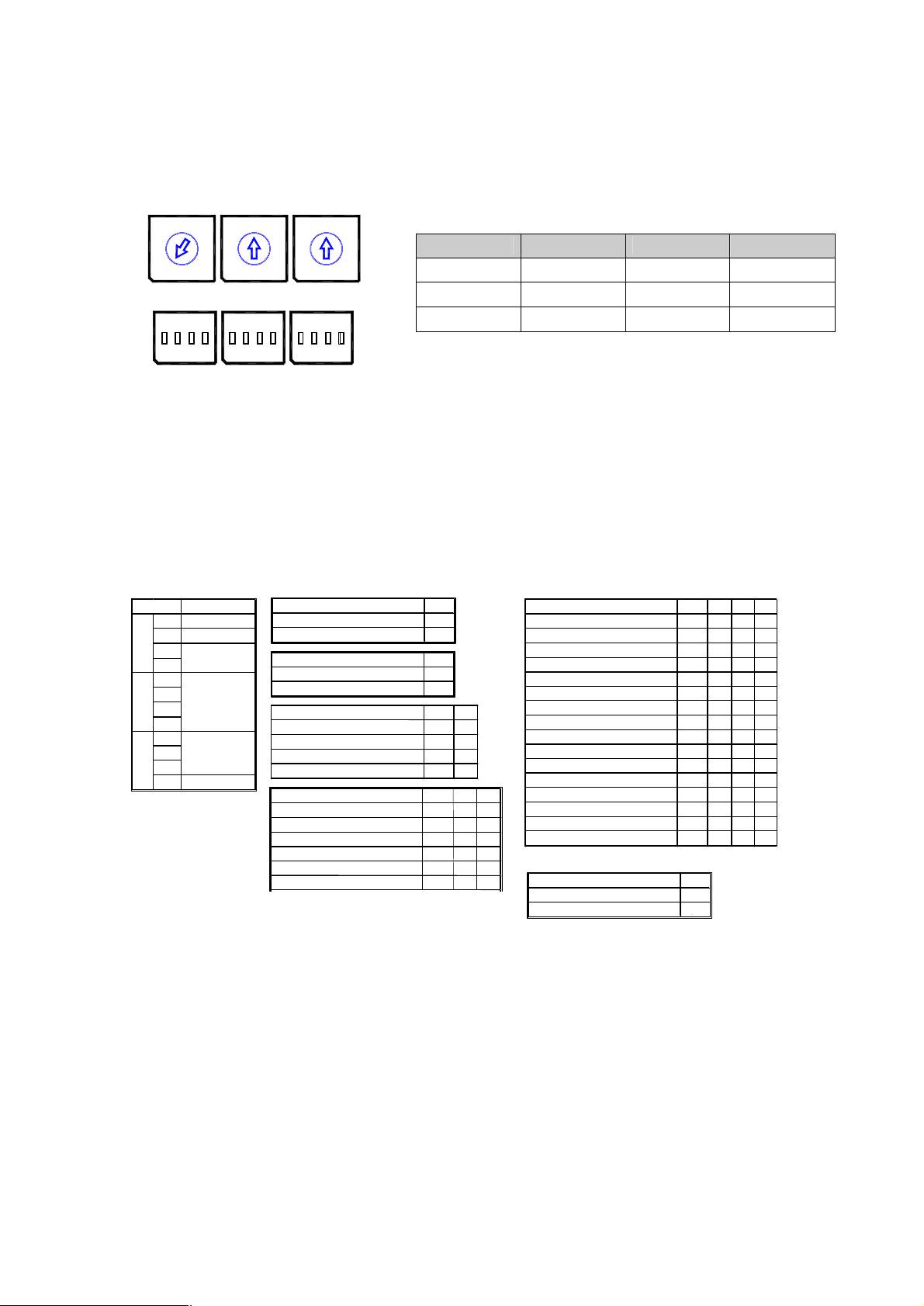
The dome camera must be installed by qualified service personnel. Before installing the dome
camera system this instruction manual must be read thoroughly and understood fully. Dome
cameras must be set up properly before starting the installation. This involves properly setting
configuration switches. Figure 3 shows the location of these switches.
0
0
0
1
1
1
9
9
9
2
2
2
8
8
8
3
3
3
7
7
7
4
4
4
6
6
6
5
5
5
Selection Switches
Selection Switches
S1 S2 S3
S6S5S4
Protocol Selection Switches
Figure 3– Layout of Switches
2.3 Principle of Termination
Every device which is connected at the end of the communication data line must be terminated
by either DIP switch setting or appropriate devices such as a termination jumper to prevent
potential control signal errors.
See Figure 4 for termination switch settings and Figure 5 for examples of devices requiring
termination. Note : Total length of the cable for communication should not exceed 1.2Km.
SW2 1 2
ON
SW2
1 2
Terminated ON ON
Not terminated OFF OFF
Figure 4– Setting Dome Camera Termination
10

S1:Dome1 port Termination ON
SW2:Termination ON
S1:Dome1 port Termination ON
SW2:Termination ON SW2:Termination ON
SW2:Termination ON
S1:Dome1 port Termination ON
SW2:Termination ON
DVR Termination ON
DVR Termination ON
SW2:Termination ON
S4:DVR port Termination ON
DVR Termination ON
SW2:Termination ON
DVR Termination ON
SW2:Termination ON
S1:Dome1 port Termination ON
SW2:Termination ON
S3:Dome2 port Termination ON
SW2:Termination ON
SW2:Termination ON
TERMINATION ON
Figure 5- Termination Diagram
2.4 Dome Camera Address (ID)
Each dome camera must have a unique address (ID). Identical IDs on the same line may
damage the control circuit caused by an electrical short. When installing multiple dome cameras
or a DVR, it is recommended that the dome camera IDs be identical to the camera port of the
DVR.
Cam Port 1 = Dome ID1, Cam Port 2 = Dome ID 2 … Cam Port 16 = Dome ID 16.
If more than 16 dome cameras are installed using two or more DVRs the following formula is
useful to determine the Dome ID: ID =16x(n-1)+m ( where n= number of DVR, m=Camera Port)
11
Refer to Figures 6 for setting the dome camera address (ID) and protocol selection.
OFF
ON
D3 D4
On
On On
D5 D6 D7 D8
S2
PD On
VN
SN On On On
DC
On On On On
D9
On
On
S1
456
3
2
7
8
9
1
0
S4
on on on
S2
5
6
4
3
2
7
8
9
1
0
S5
S3
5
6
4
3
2
9
1
0
S6
7
8
DOME ID
S3 S2 S1
1 0 0 1
.
999
. . .
9 9 9
Figure 6– Setting Dome Camera Address (ID) and Protocol
2.5 Setting Protocols
A ScanDome camera is capable of negotiating with multiple protocols if the communication
speed is matched (same baud rate i.e., 9600 bps). See Figure 7 for the appropriate protocol
switch settings.
Note : Consult service personnel if a dome camera is installed with a device other than a
ScanDome Controller.
Dip s/w
S4
S5
S6
Function
D1 VIDEO
D2 COMM.
D3
Camera
D4
D5
D6
Protocol
D7
D8
D9
Baud rate
D10
D11
D12Extended ID
VIDEO D1
NTSC Off
PAL On
COMMUNICATION D2
RS-422 On
RS-485 Off
Camera
Default
RESERVED
RESERVED
RESERVED
Baud rate
2400 bps
4800 bps
9600 bps
19200 bps
38400 bps
57600 bps
2.6 Connections
• How to Connect RS485/422
The dome camera has a built-in RS-485/422 receiver so that it can be controlled
remotely by an external control device such as a joystick controller or DVR.
Protocol
S2/E,PL,ER,PH(No)
S2/E,PL,ER,PH(Even) On Off Off Off
PL
RESERVED
Off Off
Off
Off On
D10 D11
Off Off Off
Off Off On
Off On Off
Off On On
Off Off
Off On
RESERVED
RESERVED
RESERVED
RESERVED
VCL
KD6
Factory Default
Extended Dome ID D12
0~999 On
1000~3999 Off
Figure 7– Protocol Selection tables
Off Off Off Off
Off On Off Off
On On Off Off
Off Off On Off
Off On Off
Off On On Off
Off
Off Off Off On
On Off Off On
Off On Off On
On On Off On
Off Off On On
On Off On On
Off On On On
RS-485: Connect the TXA(Tx+) and TXB(Tx-) of the RS485 control devices ( KDB,
DVR…)to RX+, RX- of the dome camera.
12
 Loading...