

Page 1
HRG Performance Series DVR
CAUTION
THIS SYMBOL INDICATES THAT
DANGEROUS VOLTAGE
CONSTITUTING A RISK OF
ELECTRIC SHOCK IS PRESENT
WITHIN THE UNIT.
CAUTION: TO REDUCE THE RISK OF ELECTRIC
SHOCK, DO NOT REMOVE THE COVER.
NO USER-SERVICEABLE PARTS INSIDE.
REFER SERVICING TO QUALIFIED SERVICE
PERSONNEL.
THIS SYMBOL INDICATES THAT
IMPORTANT OPERATING AND•
MAINTENANCE INSTRUCTIONS
ACCOMPANY THIS UNIT.
RISK OF ELECTRIC
SHOCK
DO NOT OPEN
Getting Started Guide 1
Document 800-13894 – Rev A – 01/2013
This document describes the installation and operation procedures for the following
Performance Series Honeywell DVRs:
• HRG4 4-Channel DVR (HRG4X, HRG41X, HRG45X)
• HRG8 8-Channel DVR (HRG8X, HRG81X, HRG82X)
• HRG16 16-Channel DVR (HRG16X, HRG161X, HRG162X, HRG164X)
This document is for system integrators, installers, and end-user operators.
For more detailed information than is contained in this guide, refer to the User Guide,
located on the software CD.
Cautions and Warnings
Compliance
Manufacturer’s Declaration of Conformance
CAUTION Use only the supplied power supply.
The manufacturer declares that the equipment supplied is compliant with the essential
requirements of the EMC directive 2004/108/EC and Low Voltage Directive 2006/95/EC
conforming to the requirements of standards EN 55022 for emissions, EN 55024 for
immunity, and EN 60950-1 for electrical equipment safety.
Document 800-13894 – Rev A – 01/2013
Page 2

2 | HRG Performance Series DVR Getting Started Guide
Safety Instructions
BEFORE OPERATING OR INSTALLING THE UNIT, READ AND FOLLOW ALL
INSTRUCTIONS.
AFTER INSTALLATION, retain the safety and operating instructions for future reference
1. HEED WARNINGS - Adhere to all warnings on the unit and in the operating instructions.
2. INSTALLATION
• Install in accordance with the manufacturer’s instructions.
• Installation and servicing should be performed only by qualified and experienced
technicians to conform to all local codes and to maintain your warranty.
• Do not install the unit in an extremely hot or humid location, or in a place subject to
dust or mechanical vibration. The unit is not designed to be waterproof. Exposure to
rain or water may damage the unit.
• Any wall or ceiling mounting of the product should follow the manufacturer’s
instructions and use a mounting kit approved or recommended by the manufacturer.
3. POWER SOURCES - This product should be operated only from the type of power source
indicated on the marking label. If you are not sure of the type of power supplied to your
facility, consult your product dealer or local power company.
4. HEAT - Situate away from items that produce heat or are heat sources such as radiators,
heat registers, stoves, or other products (including amplifiers).
5. WATER AND MOISTURE - Do not use this unit near water or in an unprotected outdoor
installation, or any area classified as a wet location.
6. MOUNTING SYSTEM - Use only with a mounting system recommended by the
manufacturer, or sold with the product.
7. ATTACHMENTS - Do not use attachments not recommended by the product
manufacturer as they may result in the risk of fire, electric shock, or injury to persons.
8. ACCESSORIES - Only use accessories specified by the manufacturer.
9. CLEANING - Do not use liquid cleaners or aerosol cleaners. Use a damp cloth for
cleaning.
10. SERVICING - Do not attempt to service this unit yourself as opening or removing covers
may expose you to dangerous voltage or other hazards. Refer all servicing to qualified
service personnel.
11. REPLACEMENT PARTS - When replacement parts are required, be sure the service
technician has used replacement parts specified by the manufacturer or have the same
characteristics as the original part. Unauthorized substitutions may result in fire, electric
shock or other hazards.
www.honeywellvideo.com
Page 3

Before you Begin Installation
Unpack everything. Ensure that the items received match those listed on the order form and
packing slip. In addition to your DVR and this Getting Started Guide, the packing box should
include:
• an IR remote control
•a USB mouse
•a power adapter
• a CD/DVD containing the software and the User Guide
Note Other peripheral hardware (owner supplied) will be required for your installation
(for example, Honeywell cameras, a VGA monitor, and appropriate cabling). See
the User Guide for more information.
| 3
Installing the DVR
When installing the DVR:
• Ensure there is ample room for audio and video cables.
• When installing cables, ensure that the bend radius of the cables are no less than five
times than its diameter.
• Connect both the alarm and RS-485 cable.
• Allow at least 2 cm of space between devices if rack mounted.
• Ensure the DVR is grounded.
• Ensure that the environmental temperature is within the range of -10 °C to 55 °C.
• Ensure that the environmental humidity is within the range of 10% to 90%.
800-13894 - A - 01/2013
Page 4
4 | HRG Performance Series DVR Getting Started Guide
12 3 4 5 6
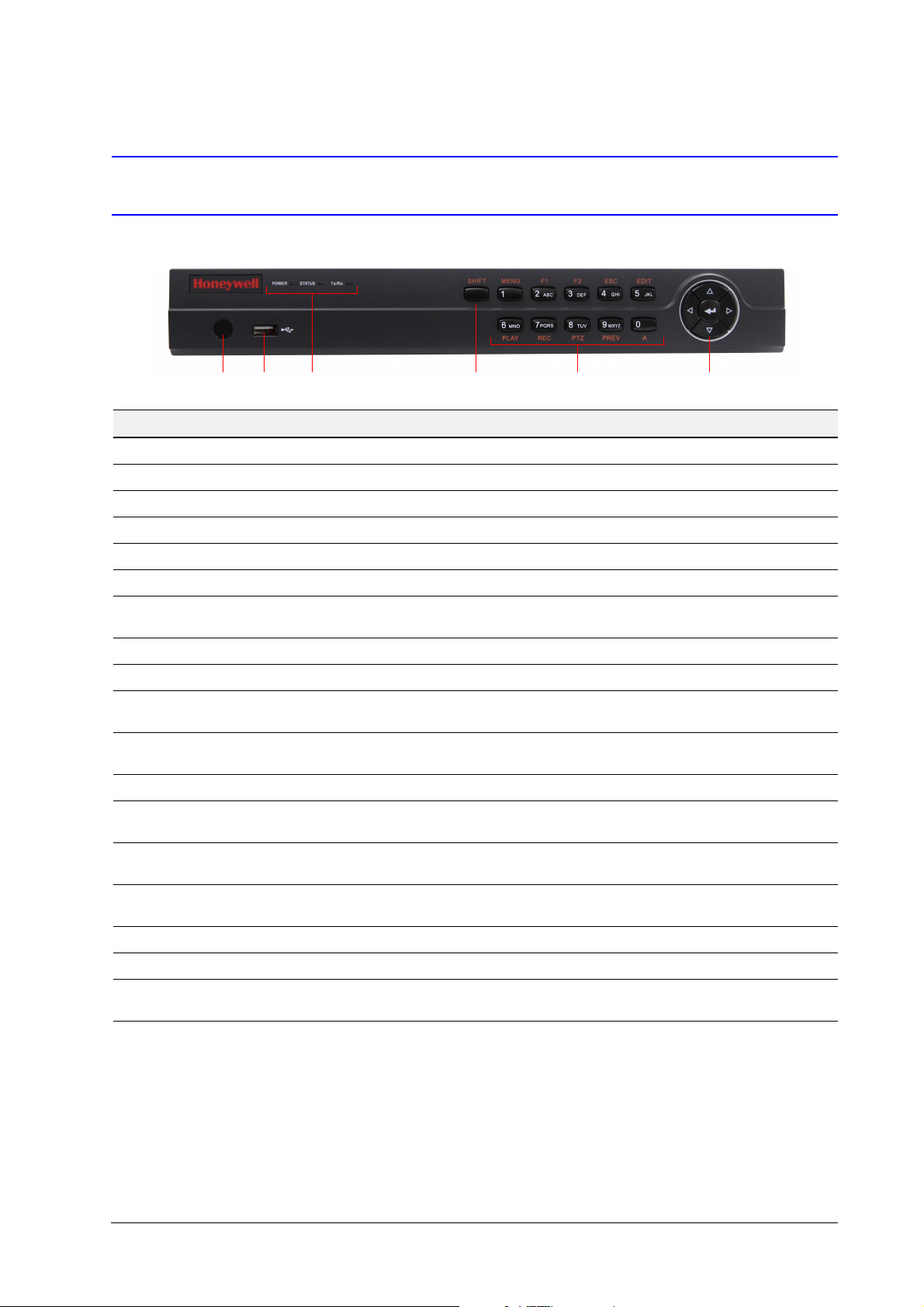
DVR Front Panels
4-Channel HRG
Position Control/Indicator Function
1 IR Receiver Sensor for IR Remote Controller.
2 USB Port Connection for a USB mouse or USB flash memory device.
3 Status Indicators
POWER Turns green when the HRG DVR is on.
STATUS Illuminates when the compound key switches to numeric/letter input mode.
Tx/Rx Flickers green when the network connection is functioning normally.
4SHIFT
5Compound Buttons
1/MENU Enter number “1”; Access the main menu.
2/ABC/F1
3/DEF/F2
4/GHI/ESC Enter number “4” or letters “G”, “H”, “I”; Exit and back to the previous menu.
5/JKL/EDIT
6/MNO/PLAY
7/PQRS/REC
8/TUV/PTZ Enter number “8” or letters “T”, “U”, “V”; Access to PTZ control interface.
9/WXYZ/PREV Enter number “9” or letters “W”, “X”, “Y”, “Z”; Multi-camera display in live view.
0/A
6 Control Buttons
Switches the compound keys functions from inputting the numeric/letter values to the
functional controls.
Enter number “2” or letters “A”, “B”, “C”; The F1 button when used in a list field will
select all items on the list. In PTZ Control mode, it will turn on/off PTZ light.
Enter number “3” or letters “D”, “E”, “F”; The F2 button is used to cycle through tab
pages. It will also bring up the Channel and OSD Position settings.
Enter number “5” or letters “J”, “K”, “L”; Delete characters before cursor; Select the
check box and ON/OFF switch; Start/stop record clipping in playback.
Enter number “6” or letters “M”, “N”, “O”; Playback, for direct access to playback
interface.
Enter number “7” or letters “P”, “Q”, “R”, “S”; Manual record, for direct access to
manual record interface; manually enable/disable record.
Enter number “0”; Switch between input methods (upper and lowercase alphabet,
symbols and numeric input).
Directional buttons: In menu mode, the direction buttons are used to navigate
between different fields and items and select setting parameters. In playback mode, the
Up and Down buttons are used to speed up and slow down record play, and the Left
and Right buttons are used to select the recording 30s forwards or backwards. In Live
View mode, these buttons can be used to cycle through channels.
Enter: The Enter button is used to confirm selection in the Menu mode; or used to
select check box fields and ON/OFF switch. In playback mode, it can be used to play
or pause the video. In single-frame play mode, pressing the Enter button advances the
video by a single frame. And in auto sequence live view mode, the buttons can be used
to pause / resume auto sequence.
www.honeywellvideo.com
Page 5
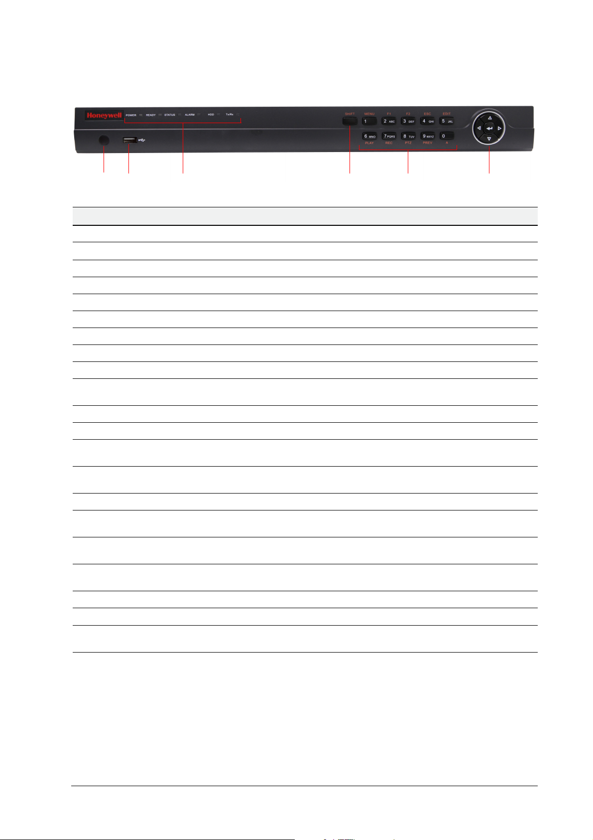
8-Channel/16-Channel HRG
12 3 4 5 6
Position Control/Indicator Function
1 IR Receiver Sensor for IR Remote Controller.
| 5
2 USB Port
3 Status Indicators
POWER Turns green when the HRG DVR is on.
READY Turns green when the device is running normally.
STATUS Illuminates when the compound key switches to numeric/letter input mode.
ALARM Turns red when there is a sensor alarm occurring.
HDD Flickers red when the HDD is reading or writing.
Tx/Rx Flickers green when the network connection is functioning normally.
4SHIFT
5 Compound Buttons
1/MENU Enter number “1”; Access the main menu.
2/ABC/F1
3/DEF/F2
4/GHI/ESC Enter number “4” or letters “G”, “H”, “I”; Exit and back to the previous menu.
5/JKL/EDIT
6/MNO/PLAY
7/PQRS/REC
8/TUV/PTZ Enter number “8” or letters “T”, “U”, “V”; Access to PTZ control interface.
9/WXYZ/PREV Enter number “9” or letters “W”, “X”, “Y”, “Z”; Multi-camera display in live view.
Connection for a USB mouse or USB flash memory device.
Switches the compound keys functions from inputting the numeric/letter values to the
functional controls.
Enter number “2” or letters “A”, “B”, “C”; The F1 button when used in a list field will
select all items on the list. In PTZ Control mode, it will turn on/off PTZ light.
Enter number “3” or letters “D”, “E”, “F”; The F2 button is used to cycle through tab
pages. It will also bring up the Channel & OSD Position settings.
Enter number “5” or letters “J”, “K”, “L”; Delete characters before cursor; Select the
check box and ON/OFF switch; Start/stop record clipping in playback.
Enter number “6” or letters “M”, “N”, “O”; Playback, for direct access to playback
interface.
Enter number “7” or letters “P”, “Q”, “R”, “S”; Manual record, for direct access to
manual record interface; manually enable/disable record.
0/A
6 Control Buttons
Enter number “0”; Switch between input methods (upper and lowercase alphabet,
symbols and numeric input).
Directional buttons: In menu mode, the direction buttons are used to navigate
between different fields and items and select setting parameters. In playback mode, the
Up and Down buttons are used to speed up and slow down record play, and the Left
and Right buttons are used to select the recording 30s forwards or backwards. In Live
View mode, these buttons can be used to cycle through channels.
Enter: The Enter button is used to confirm a selection in the Menu mode; or used to
select check box fields and the ON/OFF switch. In playback mode, it can be used to
play or pause the video. In single-frame play mode, pressing the Enter button advances
the video by a single frame. And in auto sequence live view mode, the buttons can be
used to pause / resume auto sequence.
800-13894 - A - 01/2013
Page 6
6 | HRG Performance Series DVR Getting Started Guide
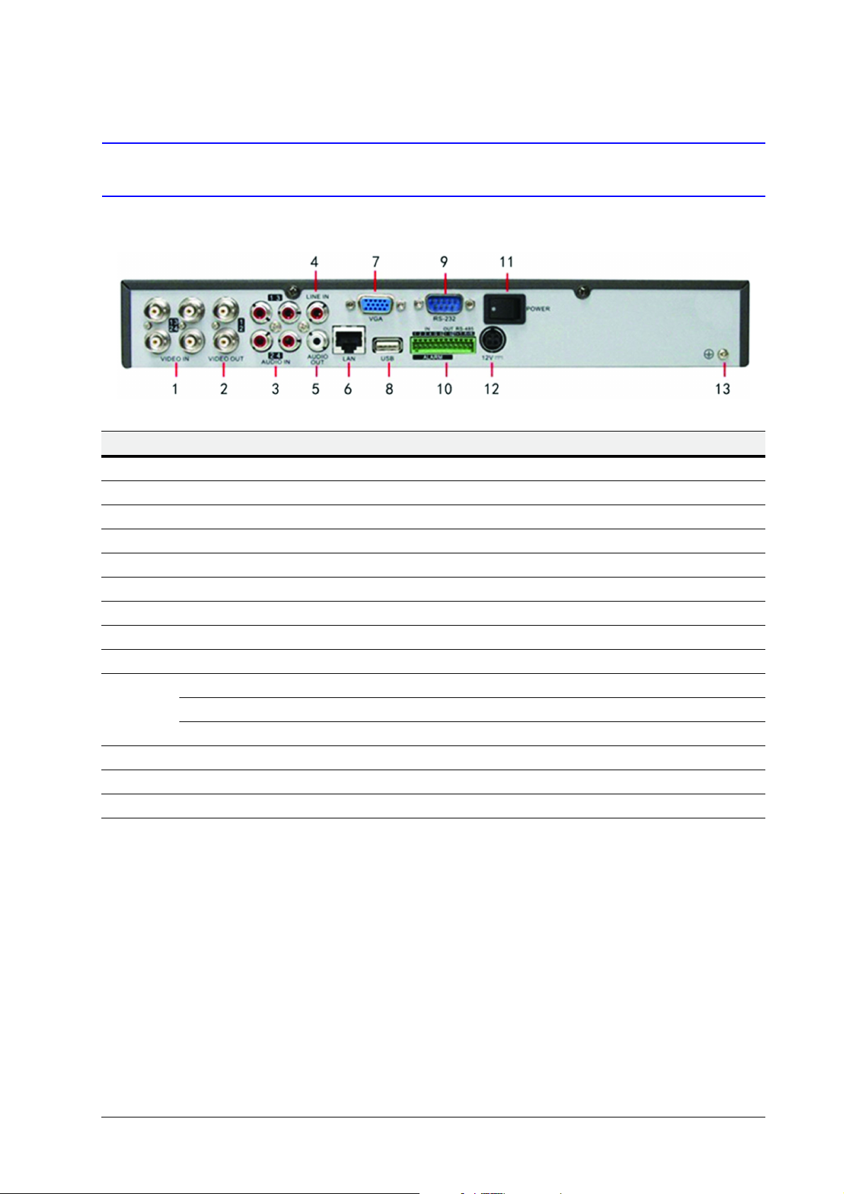
DVR Back Panels
4-Channel HRG
Position Connection/Switch Function
1Video In BNC connectors for analog video input.
2Video Out BNC connectors for video output
3Audio In RCA connectors for analog audio input.
4Line In RCA connector for audio input.
5Audio Out RCA connector for audio output.
6LAN Connector for LAN (Local Area Network).
7VGA DB15 connector for VGA output. Display local video output and menu.
8USB Connector for USB devices.
9 RS-232 Port DB9 connector for RS232 devices.
Alarm In Connector for alarm input.
10
11 Power Switch for turning On/Off the device.
12 12 V 12 V DC power supply.
13 GND Ground (needs to be connected when DVR starts up).
Alarm Out Connector for alarm output.
RS-485 Port Connector for RS-485 devices. T+, T– pins connect to PTZ.
www.honeywellvideo.com
Page 7
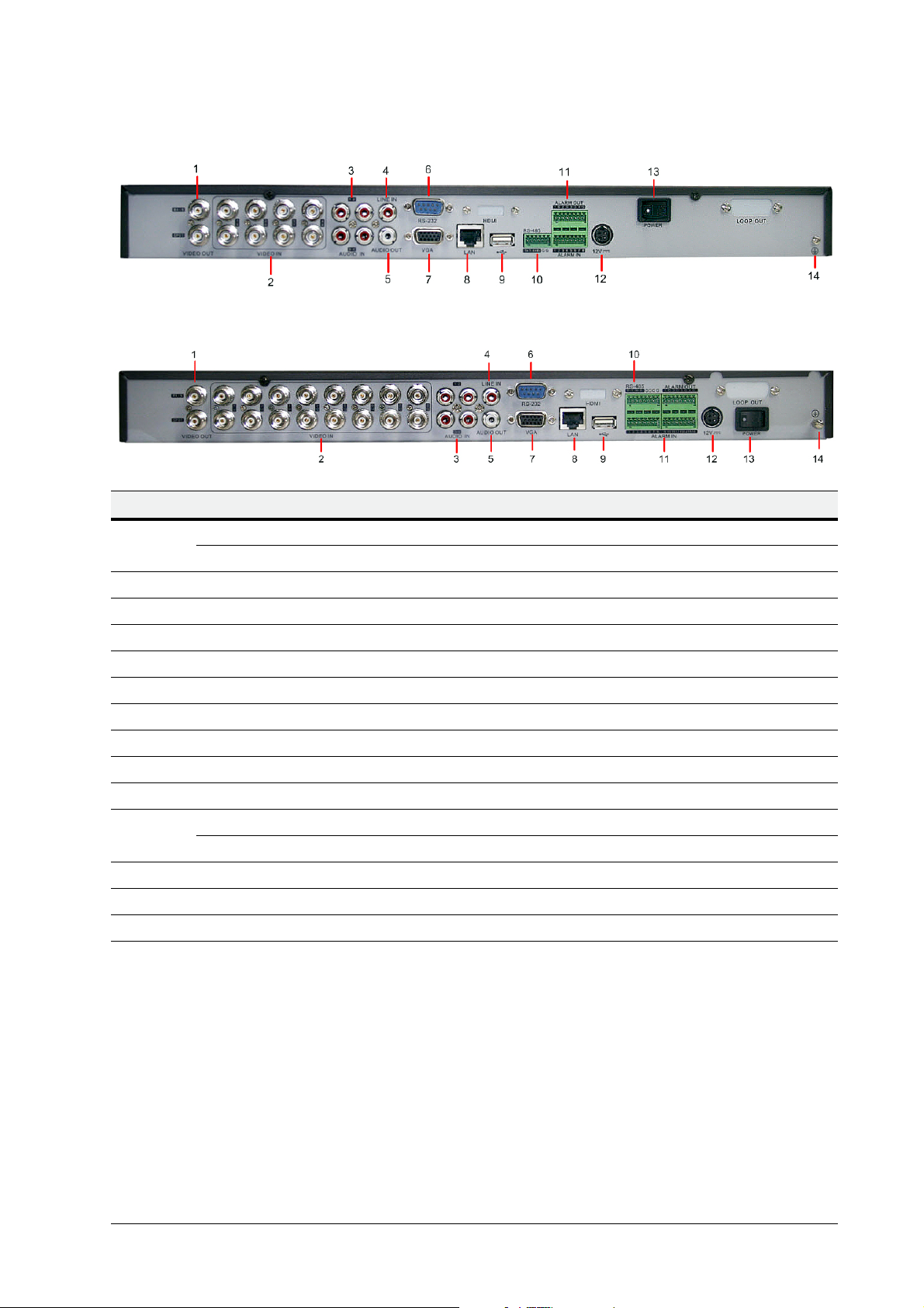
8-Channel HRG
16-Channel HRG
Position Connection/Switch Function
| 7
1
2Video In BNC connectors for analog video input.
3Audio In RCA connectors for analog audio input.
4Line In RCA connector for audio input.
5Audio Out RCA connector for audio output.
6 RS-232 Port DB9 connector for RS232 devices.
7VGA DB15 connector for VGA output. Display local video output and menu.
8LAN Connector for LAN (Local Area Network).
9USB Connector for USB devices.
10 RS-485 Port Connector for RS-485 devices. T+, T– pins connect to PTZ.
11
12 12 V 12 V DC power supply.
13 Power Switch for turning On/Off the device.
14 GND Ground (needs to be connected when DVR starts up).
Main Video Out BNC connectors for analog video input.
Local Video Out BNC connectors for local video out
Alarm In Connector for alarm input.
Alarm Out Connector for alarm output.
800-13894 - A - 01/2013
Page 8

8 | HRG Performance Series DVR Getting Started Guide
4-Channel HRG model shown
Connecting the DVR
Connecting to Alarm Inputs/Outputs
Connect the alarm inputs and outputs as shown below:
Connecting to an Non Open/Closed Relay
The alarm input requires an open/closed dry contact relay. If the input is not an open/closed dry
contact relay, connect as shown below:
Connecting Alarm Output Relays
The alarm output relay must be used with external DC loads only within a limit of 12 V DC/1 A.
Note The DVR Alarm-out relay does not support connection to an AC load. An external
relay is needed to isolate the AC loads from the DVR.
www.honeywellvideo.com
Connecting Alarm Devices to the DVR
1. Disconnect the pluggable block from the ALARM IN /ALARM OUT terminal block.
2. Loosen the stop screws from the pluggable block, insert the signal cables into the slots
and then retighten the stop screws. Ensure that the signal cables are securely fastened.
3. Reconnect the pluggable block to the terminal block.
Page 9

Connecting RS-485 Devices to the DVR
Terminal block
Pluggable block
1. Disconnect the pluggable block from the RS-485 terminal block.
| 9
2. Loosen the stop screws from the pluggable block, insert the signal cables into the slots,
and then retighten the stop screws. Ensure signal cables are securely fastened.
3. Reconnect the pluggable block to the terminal block.
Note Connect the pan/tilt receiver unit to the T+ and T– terminals on the DVR.
HDD Storage Calculation Chart
The following chart shows an estimation of storage space used based on recording at one
channel for an hour at a fixed bit rate.
Bit Rate Storage Used Bit Rate Storage Used
96K 42M 512K 225M
128K 56M 640K 281M
160K 70M 768K 337M
192K 84M 896K 393M
224K 98M 1024K 450M
256K 112M 1280K 562M
320K 140M 1536K 675M
384K 168M 1792K 787M
448K 196M 2048K 900M
800-13894 - A - 01/2013
Page 10

10 | HRG Performance Series DVR Getting Started Guide
Note The supplied values for storage space used is just for reference. Storage space
used is estimated by formulas and may have some deviation from actual value.
Download the storage estimator found on the HRG Series DVR product web
page. Go to Products on the Honeywell Video Systems web site
(www.honeywellvideo.com).
DVR Operation
Menu Structure
Starting Up and Shutting Down the DVR
Proper startup and shutdown procedures are crucial to maintaining the life of your DVR.
Starting Up the DVR
1. Ensure the power supply is plugged into an electrical outlet. It is HIGHLY recommended
that you use an Uninterruptible Power Supply (UPS) in conjunction with the unit.
2. Press the POWER switch on the rear panel. After the power has been started up, the
POWER indicator on the DVR will light green.
www.honeywellvideo.com
Page 11

Shutting Down the DVR
1. Enter the Shutdown menu by clicking on Menu ShutDown.
2. Click ShutDown.
3. Click Yes in the pop-up window to confirm that you want to shut down the DVR.
| 11
Setting Up the DVR with the Setup Wizard
Note Please ensure that the DVR has been installed with HDD before access to the
Setup Wizard. By default, the Setup Wizard will start once the DVR has loaded.
The Setup Wizard will guide you through some important settings of your DVR.
Select Next if the DVR has been installed with HDD, or click Cancel to access
Live View window if no HDD is installed.
By default, the Setup Wizard will start after the DVR has loaded. The Setup Wizard will walk you
through some of the more important settings of your DVR. If you do not wish to use the Setup
Wizard at this time, click the Cancel button. You can also choose to use the Setup Wizard at a
later time by leaving the Start Wizard when DVR starts? check box checked.
800-13894 - A - 01/2013
Page 12

12 | HRG Performance Series DVR Getting Started Guide
Using the Setup Wizard for Initial Setup
1. Click Next on the Wizard window. This will take you to the User Permission window.
2. Navigate to the Admin Password input field. Enter the admin password into the Admin
Password input field. By default, the password is 12345.
3. Check the New Admin Password check box to change the admin password. Enter the
new password and confirm the password in the given fields.
4. Click Next. The HDD Management window opens.
5. Click Enter to start HDD management.
6. If a new HDD was recently installed, select the HDD from the list to initialize it. Initializing
the HDD will format and remove all data from it.
7. Click OK after the HDD has been initialized. You will return to the Setup Wizard.
www.honeywellvideo.com
Page 13

8. Click Next. The Record Settings window opens.
9. Click Enter to enter the Record Settings window.
10. Select the Schedule tab.
| 13
11. Click Edit. A new recording schedule opens.
12. Check both the Enable Schedule and All Day boxes. This enables the recording
schedule and allows it to record continuously all day.
13. Click OK to return to the Schedule tab.
800-13894 - A - 01/2013
Page 14

14 | HRG Performance Series DVR Getting Started Guide
Note To copy the schedule to a different channel, select the channel or all under Copy
To, then click Copy.
14. Click Next. The Network Settings window opens.
15. Click Enter to configure the network settings. The Network Settings window opens.
16. Enter the IP Address, Subnet Mask, and Default Gateway.
17. Click OK to return to the Setup Wizard.
18. Click Done if you are satisfied with all of the settings you have entered. This finishes the
setup procedure and closes the Setup Wizard.
This completes this initial setup process. Continue to Setting the Date and Time.
www.honeywellvideo.com
Page 15

Setting the Date and Time
It is extremely important to setup the system date and time to accurately time stamp recordings
and events.
| 15
Live View
1. Click Menu
2. Enter the correct date and time in the System Time field.
3. Click Apply to save the changes.
Settings General to enter the General Settings menu.
Live View Icons
Some icons are provided on screen in Live View mode to indicate different camera status.
Icon What it indicates
Main output
Auxiliary output
Event Alarm Indicates video loss, video tampering, motion detection or relay
alarm.
Record Indicates the current channel is recording. The recording may have been
started manually, from a schedule, and/or triggered from motion or alarm.
Event Alarm and Record
Controlling PTZ Cameras
Settings for a PTZ camera must be configured before it is used. Before proceeding, verify that
the PTZ and RS-485 of the DVR are connected properly.
800-13894 - A - 01/2013
Page 16

16 | HRG Performance Series DVR Getting Started Guide
Control Action
Call Preset Call a PTZ preset.
Call Patrol Call a PTZ patrol.
Call Pattern Call a PTZ pattern.
Preset Settings Enter the PTZ preset configuration menu.
Patrol Settings Enter the PTZ patrol configuration menu.
Pattern Settings Enter the PTZ pattern configuration menu.
PTZ Menu Enter the PTZ menu.
PTZ Settings Enter the PTZ Settings menu.
Configuring PTZ Settings
1. Click Menu Settings PTZ to enter the PTZ Settings menu.
2. Select, next to the Camera label, the channel where the PTZ camera is installed.
3. Configure the settings for baud rate, date bit, stop bit, parity, flow control, PTZ protocol
and address.
4. Click OK to save the changes and exit the PTZ Settings window.
Controlling PTZ Cameras with the PTZ Control Panel
The PTZ control panel in the live view window provides a series of PTZ control buttons, as shown
in the following figure:
www.honeywellvideo.com
Page 17

Controlling PTZ Cameras with the Live View Menu
3
2
1
4
56789
# Control Action
1Directional
Pad/Auto-scan
Buttons
Controls the movements and directions of
the PTZ. The center button is also used to
start auto-scan of PTZ.
2 Zoom Used to zoom in and out with the PTZ.
3Focus Used to adjust the focus of the PTZ.
4 Iris Used to open or close the iris of the PTZ.
5 Speed Adjusts the movement speed of the PTZ.
6 Light Turns the PTZ light (if applicable) on and off.
7 Wiper Turns the PTZ wiper (if applicable) on and
off.
8 Zoom In Instantly zooms PTZ in.
9 Center Centers PTZ. Camera: Select a PTZ camera.
| 17
Playback
Playback of Recorded Video
To play back files from a general search:
1. Click Menu
2. Select the General tab, then set the search parameters by selecting cameras to search, a
video/file type, and the start and end times.
Video Search to enter the Video Search menu.
800-13894 - A - 01/2013
Page 18

18 | HRG Performance Series DVR Getting Started Guide
3. Click Play to start playback of all the files that met the specified search criteria.
– OR –
Click Search to bring up a list of search results. From this list of search results, you can
select a file to play back, and then click Play to enter synchronous playback cameras
selection.
Recorded video will automatically play back in the Playback interface (above).
Playback in Live View
You can also instantly playback from a channel while watching a Live View. The playback will
be of recordings from the past 5 minutes. You can use the USB mouse or the DVR front panel
controls or the remote control for playback.
Using a Mouse for Playback
• Right-click the mouse on the desired channel, then select the Playback button.
Recordings from the selected channel will start playing back in the Playback interface. An
Attention message will appear if there are no recordings found from the previous 5 minutes. You
may also press the Play button to view the day's recording for the selected channel.
You can also select additional channels for playback from the channel list on the right hand side
of the Playback interface.
Using the Front Panel/Remote Controls
1. Press the Play button. The Playback interface opens.
2. Use the front panel or the remote to enter the channel for which you would like to view
recordings.
For the remote control, press SHIFT. The STATUS light turns green. Then press the
number buttons to select a channel.
Playback of recorded video begins.
www.honeywellvideo.com
Page 19

Playing Video from the System Log
1. Click Menu Maintenance Log Search to enter the Log Search menu.
| 19
Backing Up
2. Select Information from the Major Type drop-down menu.
3. Select Start Record or End Record from the Minor Type drop-down menu.
4. Select a Start and End time.
5. Click Search.
A list of search results is displayed.
6. Select a video log for playback, then click Play.
The recording begins to play in the Playback interface.
Recorded files can be backed up to various devices, such as USB flash drives, USB HDDs or a
DVD writer.
1. Click Menu
Video Export to enter the Record Backup menu.
2. Select the desired search parameters to find files for export.
800-13894 - A - 01/2013
Page 20

20 | HRG Performance Series DVR Getting Started Guide
3. Click Export. The Record Backup menu opens.
4. Select the files to export. You can also click the Play button to verify that these files are
indeed the ones you would like to export.
The size of the currently selected file is displayed in the lower-left corner of the window.
5. Click Next to enter the Export menu.
6. Select a storage device for exporting from the drop-down list (USB Flash Drive, USB HDD,
www.honeywellvideo.com
or DVD Writer).
If the backup device is not recognized:
•Click Refresh.
• Reconnect the device.
• Check with the vendor for compatibility.
Page 21

7. Click Start to begin the backup process.
Confirming that the Export was Successful
| 21
When the backup process is complete, you can select the files from your device and click the
Play button to verify that they have been exported successfully.
Note The Video Player software is automatically copied onto the device to which the
recorded files were exported.
800-13894 - A - 01/2013
Page 22

Honeywell Systems (Head Office)
2700 Blankenbaker Pkwy, Suite 150
Louisville, KY 40299, USA
www.honeywellvideo.com
+1.800.323.4576
Honeywell Security Northern Europe
Ampèrestraat 41
1446 TR Purmerend, The Netherlands
www.honeywell.com/security/nl
+31.299.410.200
Honeywell Security Europe/South Africa
Aston Fields Road, Whitehouse Industrial Estate
Runcorn, WA7 3DL, United Kingdom
www.honeywell.com/security/uk
+44.01928.754028
Honeywell Security Caribbean/Latin America
9315 NW 112th Ave.
Miami, FL 33178, USA
www.honeywellvideo.com
+1.305.805.8188
Honeywell Security Pacific
Level 3, 2 Richardson Place
North Ryde, NSW 2113, Australia
www.honeywellsecurity.com.au
+61.2.9353.7000
Honeywell Security Asia
35F Tower A, City Center, 100 Zun Yi Road
Shanghai 200051, China
www.asia.security.honeywell.com
+86 21.5257.4568
Honeywell Security Middle East/N. Africa
Post Office Box 18530
LOB Building 08, Office 199
Jebel Ali, Dubai, United Arab Emirates
www.honeywell.com/security/me
+971.04.881.5506
Honeywell Security Deutschland
Johannes-Mauthe-Straße 14
D-72458 Albstadt, Germany
www.honeywell.com/security/de
+49.74 31.8 01.0
Honeywell Security France
Immeuble Lavoisier
Parc de Haute Technologie
3-7 rue Georges Besse
92160 Antony, France
www.honeywell.com/security/fr
+33.(0).1.40.96.20.50
Honeywell Security Italia SpA
Via della Resistenza 53/59
20090 Buccinasco
Milan, Italy
www.honeywell.com/security/it
+39.02.4888.051
Honeywell Security España
Avenida de Italia, n° 7, 2
a
planta
C.T.C. Coslada
28821 Coslada, Madrid, Spain
www.honeywell.com/security/es
+34.902.667.800
www.honeywellvideo.com
+1.800.323.4576 (North America only)
https://honeywellsystems.com/ss/techsupp/index.html
Document 800-13894 – Rev. A – 01/2013
© 2013 Honeywell International Inc. All rights reserved. No part of this publication may be reproduced by any means without written permission from
Honeywell. The information in this publication is believed to be accurate in all respects. However, Honeywell cannot assume responsibility for any
consequences resulting from the use thereof. The information contained herein is subject to change without notice. Revisions or new editions to this
publication may be issued to incorporate such changes.
 Loading...