

HRG Performance Series DVR
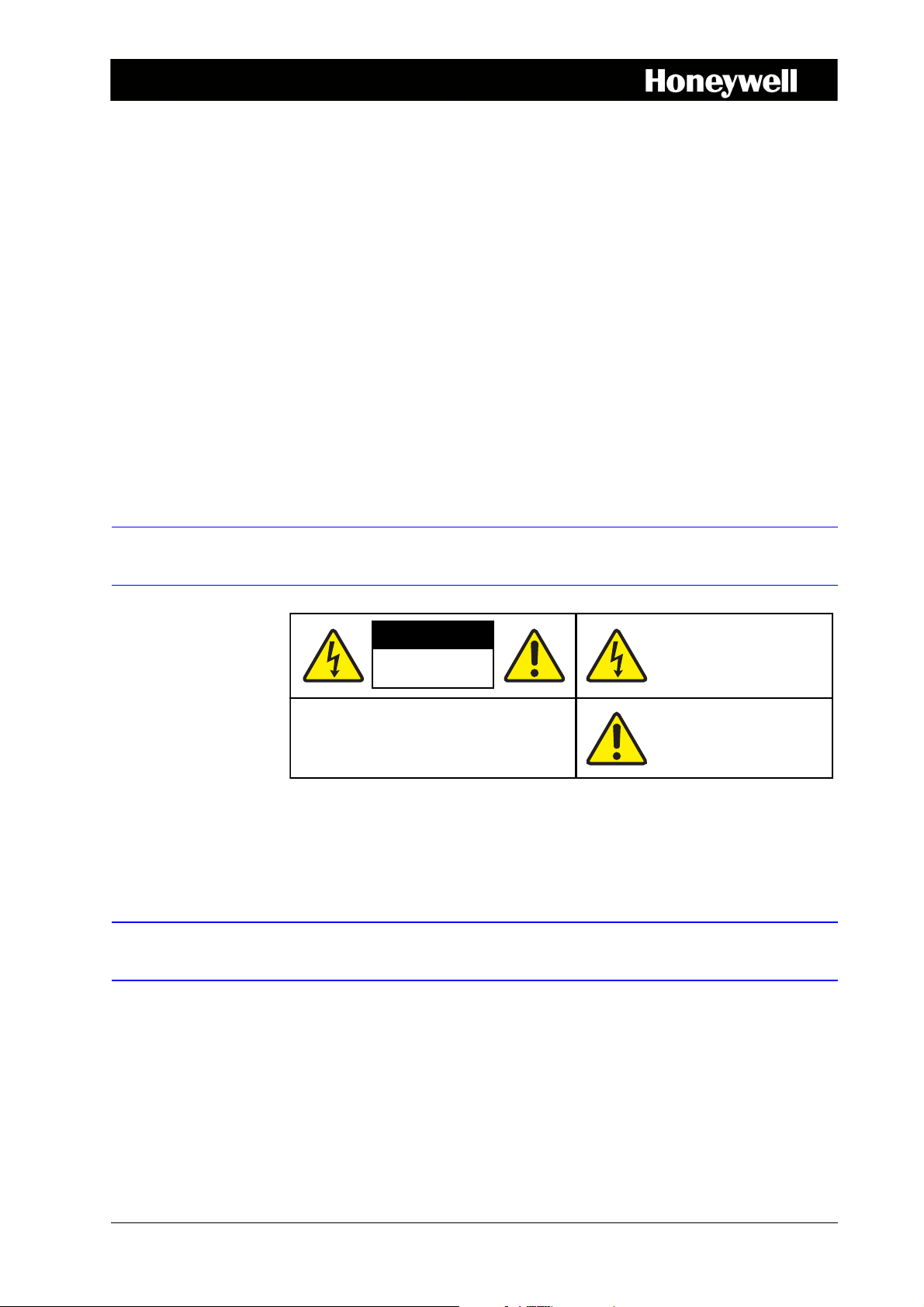
CAUTION
THIS SYMBOL INDICATES THAT
DANGEROUS VOLTAGE
CONSTITUTING A RISK OF
ELECTRIC SHOCK IS PRESENT
WITHIN THE UNIT.
CAUTION: TO REDUCE THE RISK OF ELECTRIC
SHOCK, DO NOT REMOVE THE COVER.
NO USER-SERVICEABLE PARTS INSIDE.
REFER SERVICING TO QUALIFIED SERVICE
PERSONNEL.
THIS SYMBOL INDICATES THAT
IMPORTANT OPERATING AND•
MAINTENANCE INSTRUCTIONS
ACCOMPANY THIS UNIT.
RISK OF ELECTRIC
SHOCK
DO NOT OPEN
Getting Started Guide 1
Document 800-13894 – Rev A – 01/2013
This document describes the installation and operation procedures for the following
Performance Series Honeywell DVRs:
• HRG4 4-Channel DVR (HRG4X, HRG41X, HRG45X)
• HRG8 8-Channel DVR (HRG8X, HRG81X, HRG82X)
• HRG16 16-Channel DVR (HRG16X, HRG161X, HRG162X, HRG164X)
This document is for system integrators, installers, and end-user operators.
For more detailed information than is contained in this guide, refer to the User Guide,
located on the software CD.
Cautions and Warnings
Compliance
Manufacturer’s Declaration of Conformance
CAUTION Use only the supplied power supply.
The manufacturer declares that the equipment supplied is compliant with the essential
requirements of the EMC directive 2004/108/EC and Low Voltage Directive 2006/95/EC
conforming to the requirements of standards EN 55022 for emissions, EN 55024 for
immunity, and EN 60950-1 for electrical equipment safety.
Document 800-13894 – Rev A – 01/2013

2 | HRG Performance Series DVR Getting Started Guide
Safety Instructions
BEFORE OPERATING OR INSTALLING THE UNIT, READ AND FOLLOW ALL
INSTRUCTIONS.
AFTER INSTALLATION, retain the safety and operating instructions for future reference
1. HEED WARNINGS - Adhere to all warnings on the unit and in the operating instructions.
2. INSTALLATION
• Install in accordance with the manufacturer’s instructions.
• Installation and servicing should be performed only by qualified and experienced
technicians to conform to all local codes and to maintain your warranty.
• Do not install the unit in an extremely hot or humid location, or in a place subject to
dust or mechanical vibration. The unit is not designed to be waterproof. Exposure to
rain or water may damage the unit.
• Any wall or ceiling mounting of the product should follow the manufacturer’s
instructions and use a mounting kit approved or recommended by the manufacturer.
3. POWER SOURCES - This product should be operated only from the type of power source
indicated on the marking label. If you are not sure of the type of power supplied to your
facility, consult your product dealer or local power company.
4. HEAT - Situate away from items that produce heat or are heat sources such as radiators,
heat registers, stoves, or other products (including amplifiers).
5. WATER AND MOISTURE - Do not use this unit near water or in an unprotected outdoor
installation, or any area classified as a wet location.
6. MOUNTING SYSTEM - Use only with a mounting system recommended by the
manufacturer, or sold with the product.
7. ATTACHMENTS - Do not use attachments not recommended by the product
manufacturer as they may result in the risk of fire, electric shock, or injury to persons.
8. ACCESSORIES - Only use accessories specified by the manufacturer.
9. CLEANING - Do not use liquid cleaners or aerosol cleaners. Use a damp cloth for
cleaning.
10. SERVICING - Do not attempt to service this unit yourself as opening or removing covers
may expose you to dangerous voltage or other hazards. Refer all servicing to qualified
service personnel.
11. REPLACEMENT PARTS - When replacement parts are required, be sure the service
technician has used replacement parts specified by the manufacturer or have the same
characteristics as the original part. Unauthorized substitutions may result in fire, electric
shock or other hazards.
www.honeywellvideo.com

Before you Begin Installation
Unpack everything. Ensure that the items received match those listed on the order form and
packing slip. In addition to your DVR and this Getting Started Guide, the packing box should
include:
• an IR remote control
•a USB mouse
•a power adapter
• a CD/DVD containing the software and the User Guide
Note Other peripheral hardware (owner supplied) will be required for your installation
(for example, Honeywell cameras, a VGA monitor, and appropriate cabling). See
the User Guide for more information.
| 3
Installing the DVR
When installing the DVR:
• Ensure there is ample room for audio and video cables.
• When installing cables, ensure that the bend radius of the cables are no less than five
times than its diameter.
• Connect both the alarm and RS-485 cable.
• Allow at least 2 cm of space between devices if rack mounted.
• Ensure the DVR is grounded.
• Ensure that the environmental temperature is within the range of -10 °C to 55 °C.
• Ensure that the environmental humidity is within the range of 10% to 90%.
800-13894 - A - 01/2013
4 | HRG Performance Series DVR Getting Started Guide
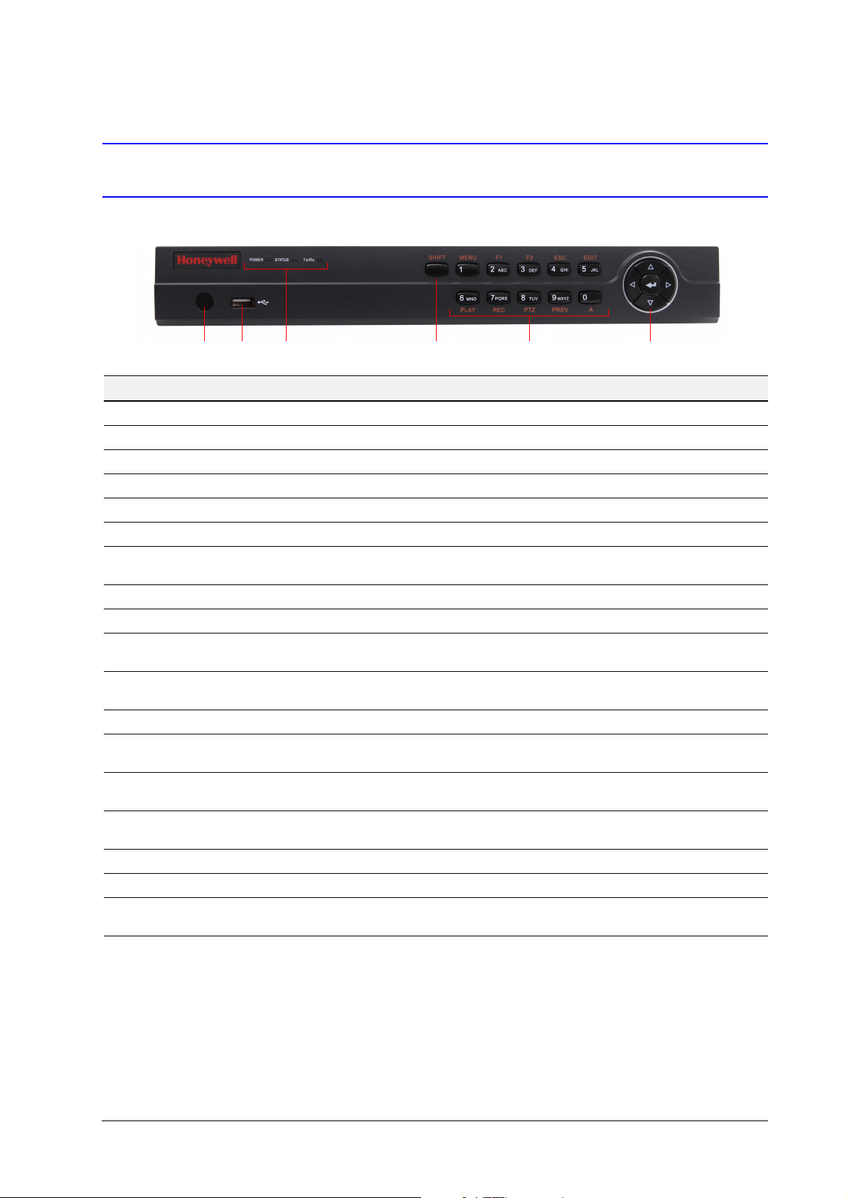
12 3 4 5 6
DVR Front Panels
4-Channel HRG
Position Control/Indicator Function
1 IR Receiver Sensor for IR Remote Controller.
2 USB Port Connection for a USB mouse or USB flash memory device.
3 Status Indicators
POWER Turns green when the HRG DVR is on.
STATUS Illuminates when the compound key switches to numeric/letter input mode.
Tx/Rx Flickers green when the network connection is functioning normally.
4SHIFT
5Compound Buttons
1/MENU Enter number “1”; Access the main menu.
2/ABC/F1
3/DEF/F2
4/GHI/ESC Enter number “4” or letters “G”, “H”, “I”; Exit and back to the previous menu.
5/JKL/EDIT
6/MNO/PLAY
7/PQRS/REC
8/TUV/PTZ Enter number “8” or letters “T”, “U”, “V”; Access to PTZ control interface.
9/WXYZ/PREV Enter number “9” or letters “W”, “X”, “Y”, “Z”; Multi-camera display in live view.
0/A
6 Control Buttons
Switches the compound keys functions from inputting the numeric/letter values to the
functional controls.
Enter number “2” or letters “A”, “B”, “C”; The F1 button when used in a list field will
select all items on the list. In PTZ Control mode, it will turn on/off PTZ light.
Enter number “3” or letters “D”, “E”, “F”; The F2 button is used to cycle through tab
pages. It will also bring up the Channel and OSD Position settings.
Enter number “5” or letters “J”, “K”, “L”; Delete characters before cursor; Select the
check box and ON/OFF switch; Start/stop record clipping in playback.
Enter number “6” or letters “M”, “N”, “O”; Playback, for direct access to playback
interface.
Enter number “7” or letters “P”, “Q”, “R”, “S”; Manual record, for direct access to
manual record interface; manually enable/disable record.
Enter number “0”; Switch between input methods (upper and lowercase alphabet,
symbols and numeric input).
Directional buttons: In menu mode, the direction buttons are used to navigate
between different fields and items and select setting parameters. In playback mode, the
Up and Down buttons are used to speed up and slow down record play, and the Left
and Right buttons are used to select the recording 30s forwards or backwards. In Live
View mode, these buttons can be used to cycle through channels.
Enter: The Enter button is used to confirm selection in the Menu mode; or used to
select check box fields and ON/OFF switch. In playback mode, it can be used to play
or pause the video. In single-frame play mode, pressing the Enter button advances the
video by a single frame. And in auto sequence live view mode, the buttons can be used
to pause / resume auto sequence.
www.honeywellvideo.com
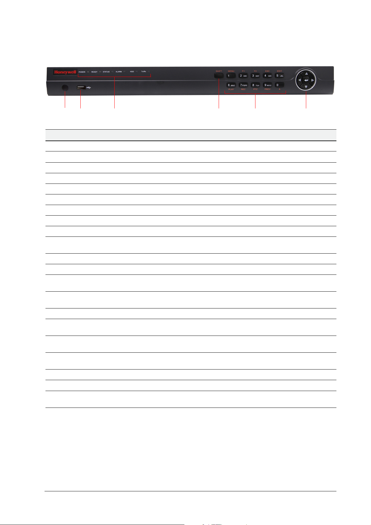
8-Channel/16-Channel HRG
12 3 4 5 6
Position Control/Indicator Function
1 IR Receiver Sensor for IR Remote Controller.
| 5
2 USB Port
3 Status Indicators
POWER Turns green when the HRG DVR is on.
READY Turns green when the device is running normally.
STATUS Illuminates when the compound key switches to numeric/letter input mode.
ALARM Turns red when there is a sensor alarm occurring.
HDD Flickers red when the HDD is reading or writing.
Tx/Rx Flickers green when the network connection is functioning normally.
4SHIFT
5 Compound Buttons
1/MENU Enter number “1”; Access the main menu.
2/ABC/F1
3/DEF/F2
4/GHI/ESC Enter number “4” or letters “G”, “H”, “I”; Exit and back to the previous menu.
5/JKL/EDIT
6/MNO/PLAY
7/PQRS/REC
8/TUV/PTZ Enter number “8” or letters “T”, “U”, “V”; Access to PTZ control interface.
9/WXYZ/PREV Enter number “9” or letters “W”, “X”, “Y”, “Z”; Multi-camera display in live view.
Connection for a USB mouse or USB flash memory device.
Switches the compound keys functions from inputting the numeric/letter values to the
functional controls.
Enter number “2” or letters “A”, “B”, “C”; The F1 button when used in a list field will
select all items on the list. In PTZ Control mode, it will turn on/off PTZ light.
Enter number “3” or letters “D”, “E”, “F”; The F2 button is used to cycle through tab
pages. It will also bring up the Channel & OSD Position settings.
Enter number “5” or letters “J”, “K”, “L”; Delete characters before cursor; Select the
check box and ON/OFF switch; Start/stop record clipping in playback.
Enter number “6” or letters “M”, “N”, “O”; Playback, for direct access to playback
interface.
Enter number “7” or letters “P”, “Q”, “R”, “S”; Manual record, for direct access to
manual record interface; manually enable/disable record.
0/A
6 Control Buttons
Enter number “0”; Switch between input methods (upper and lowercase alphabet,
symbols and numeric input).
Directional buttons: In menu mode, the direction buttons are used to navigate
between different fields and items and select setting parameters. In playback mode, the
Up and Down buttons are used to speed up and slow down record play, and the Left
and Right buttons are used to select the recording 30s forwards or backwards. In Live
View mode, these buttons can be used to cycle through channels.
Enter: The Enter button is used to confirm a selection in the Menu mode; or used to
select check box fields and the ON/OFF switch. In playback mode, it can be used to
play or pause the video. In single-frame play mode, pressing the Enter button advances
the video by a single frame. And in auto sequence live view mode, the buttons can be
used to pause / resume auto sequence.
800-13894 - A - 01/2013
6 | HRG Performance Series DVR Getting Started Guide
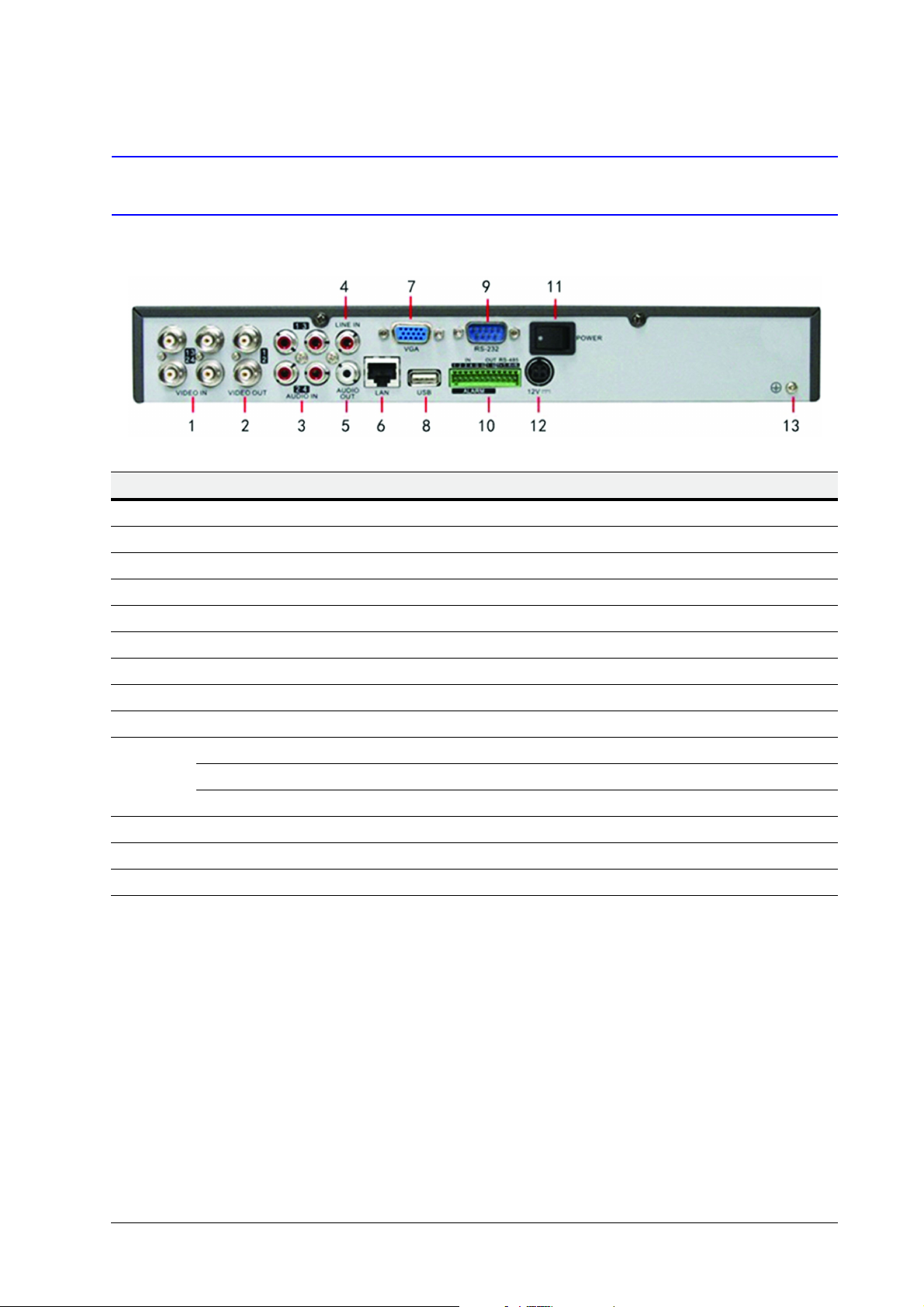
DVR Back Panels
4-Channel HRG
Position Connection/Switch Function
1Video In BNC connectors for analog video input.
2Video Out BNC connectors for video output
3Audio In RCA connectors for analog audio input.
4Line In RCA connector for audio input.
5Audio Out RCA connector for audio output.
6LAN Connector for LAN (Local Area Network).
7VGA DB15 connector for VGA output. Display local video output and menu.
8USB Connector for USB devices.
9 RS-232 Port DB9 connector for RS232 devices.
Alarm In Connector for alarm input.
10
11 Power Switch for turning On/Off the device.
12 12 V 12 V DC power supply.
13 GND Ground (needs to be connected when DVR starts up).
Alarm Out Connector for alarm output.
RS-485 Port Connector for RS-485 devices. T+, T– pins connect to PTZ.
www.honeywellvideo.com
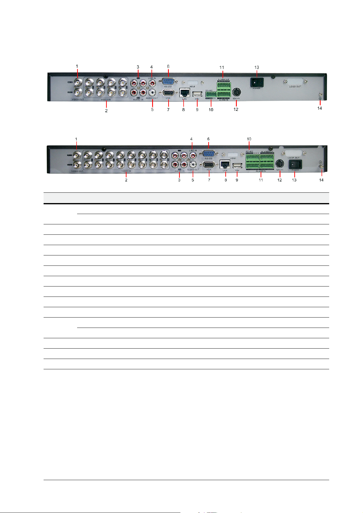
8-Channel HRG
16-Channel HRG
Position Connection/Switch Function
| 7
1
2Video In BNC connectors for analog video input.
3Audio In RCA connectors for analog audio input.
4Line In RCA connector for audio input.
5Audio Out RCA connector for audio output.
6 RS-232 Port DB9 connector for RS232 devices.
7VGA DB15 connector for VGA output. Display local video output and menu.
8LAN Connector for LAN (Local Area Network).
9USB Connector for USB devices.
10 RS-485 Port Connector for RS-485 devices. T+, T– pins connect to PTZ.
11
12 12 V 12 V DC power supply.
13 Power Switch for turning On/Off the device.
14 GND Ground (needs to be connected when DVR starts up).
Main Video Out BNC connectors for analog video input.
Local Video Out BNC connectors for local video out
Alarm In Connector for alarm input.
Alarm Out Connector for alarm output.
800-13894 - A - 01/2013
 Loading...