

Page 1

User Guide
Performance Series
Embedded DVR
HRG4
HRG8
HRG16
Document 800-12005 – Rev A – 06/2012
Page 2

Page 3

User Guide
Page 4

Revisions
Issue Date Revisions
A 06/2012 New document.
Page 5

Contents | 5
Contents 1
1 Introduction . . . . . . . . . . . . . . . . . . . . . . . . . . . . . . . . . . . . . . . . . . . . . . . 13
Overview . . . . . . . . . . . . . . . . . . . . . . . . . . . . . . . . . . . . . . . . . . . . . . . . . . . 13
Product Features . . . . . . . . . . . . . . . . . . . . . . . . . . . . . . . . . . . . . . . . . . . . 13
System Diagram . . . . . . . . . . . . . . . . . . . . . . . . . . . . . . . . . . . . . . . . . . . . . 15
Operating the HRG DVR . . . . . . . . . . . . . . . . . . . . . . . . . . . . . . . . . . . . . . . . . . . 16
Front Panel. . . . . . . . . . . . . . . . . . . . . . . . . . . . . . . . . . . . . . . . . . . . . . . . 16
Using the IR Remote Control . . . . . . . . . . . . . . . . . . . . . . . . . . . . . . . . . . . . . . 19
Using a USB Mouse . . . . . . . . . . . . . . . . . . . . . . . . . . . . . . . . . . . . . . . . . . . 20
Using the Virtual Keyboard . . . . . . . . . . . . . . . . . . . . . . . . . . . . . . . . . . . . . . . 21
Rear Panel . . . . . . . . . . . . . . . . . . . . . . . . . . . . . . . . . . . . . . . . . . . . . . . . 21
2 Getting Started . . . . . . . . . . . . . . . . . . . . . . . . . . . . . . . . . . . . . . . . . . . . . 25
Starting and Shutting Down the HRG DVR. . . . . . . . . . . . . . . . . . . . . . . . . . . . . . . . . . 25
Starting the HRG DVR . . . . . . . . . . . . . . . . . . . . . . . . . . . . . . . . . . . . . . . . . . 25
Shutting Down the HRG DVR . . . . . . . . . . . . . . . . . . . . . . . . . . . . . . . . . . . . . . 25
Rebooting and Locking the HRG DVR . . . . . . . . . . . . . . . . . . . . . . . . . . . . . . . . . . . . 26
Using the Setup Wizard . . . . . . . . . . . . . . . . . . . . . . . . . . . . . . . . . . . . . . . . . . . 26
Setting the Date and Time . . . . . . . . . . . . . . . . . . . . . . . . . . . . . . . . . . . . . . . . . . 32
3 Live View . . . . . . . . . . . . . . . . . . . . . . . . . . . . . . . . . . . . . . . . . . . . . . . . 33
On-screen Display in Live View . . . . . . . . . . . . . . . . . . . . . . . . . . . . . . . . . . . . . . . 33
Live View Icons . . . . . . . . . . . . . . . . . . . . . . . . . . . . . . . . . . . . . . . . . . . . . 33
Operating Live View . . . . . . . . . . . . . . . . . . . . . . . . . . . . . . . . . . . . . . . . . . . . . 34
Using the Mouse in Live View . . . . . . . . . . . . . . . . . . . . . . . . . . . . . . . . . . . . . . 34
Using the Digital Zoom . . . . . . . . . . . . . . . . . . . . . . . . . . . . . . . . . . . . . . . . . 35
Configuring the Live View Display . . . . . . . . . . . . . . . . . . . . . . . . . . . . . . . . . . . . . . 36
Setting the Camera Order . . . . . . . . . . . . . . . . . . . . . . . . . . . . . . . . . . . . . . . . 37
4 Recording Settings . . . . . . . . . . . . . . . . . . . . . . . . . . . . . . . . . . . . . . . . . . . 39
Configuring Recording Settings . . . . . . . . . . . . . . . . . . . . . . . . . . . . . . . . . . . . . . . 39
Initializing Recording Settings. . . . . . . . . . . . . . . . . . . . . . . . . . . . . . . . . . . . . . 39
Scheduling Recording. . . . . . . . . . . . . . . . . . . . . . . . . . . . . . . . . . . . . . . . . . 41
Starting a Manual Recording . . . . . . . . . . . . . . . . . . . . . . . . . . . . . . . . . . . . . . 42
Protecting Recorded Files . . . . . . . . . . . . . . . . . . . . . . . . . . . . . . . . . . . . . . . . . . 43
Locking and Unlocking Recorded Files. . . . . . . . . . . . . . . . . . . . . . . . . . . . . . . . . 43
Setting the Hard Drive to Read-Only . . . . . . . . . . . . . . . . . . . . . . . . . . . . . . . . . . 44
5 Playback. . . . . . . . . . . . . . . . . . . . . . . . . . . . . . . . . . . . . . . . . . . . . . . . . 47
Video Playback . . . . . . . . . . . . . . . . . . . . . . . . . . . . . . . . . . . . . . . . . . . . . . . . 47
Playback Interface . . . . . . . . . . . . . . . . . . . . . . . . . . . . . . . . . . . . . . . . . . . . 47
Playback by Search . . . . . . . . . . . . . . . . . . . . . . . . . . . . . . . . . . . . . . . . . . . 48
Playback in Live View Mode. . . . . . . . . . . . . . . . . . . . . . . . . . . . . . . . . . . . . . . 49
Playback by System Log . . . . . . . . . . . . . . . . . . . . . . . . . . . . . . . . . . . . . . . . 50
Playback Frame-by-Frame . . . . . . . . . . . . . . . . . . . . . . . . . . . . . . . . . . . . . . . 51
Digital Zoom . . . . . . . . . . . . . . . . . . . . . . . . . . . . . . . . . . . . . . . . . . . . . . . 51
6 Backup. . . . . . . . . . . . . . . . . . . . . . . . . . . . . . . . . . . . . . . . . . . . . . . . . . 53
Backing Up Recorded Files . . . . . . . . . . . . . . . . . . . . . . . . . . . . . . . . . . . . . . . . . 53
Exporting Files. . . . . . . . . . . . . . . . . . . . . . . . . . . . . . . . . . . . . . . . . . . . . . 53
Exporting Video Clips . . . . . . . . . . . . . . . . . . . . . . . . . . . . . . . . . . . . . . . . . . 55
Managing Backup Devices . . . . . . . . . . . . . . . . . . . . . . . . . . . . . . . . . . . . . . . 56
800-12005 - A - 06/2012
Page 6

6 | Performance Series DVR User Guide
7 Alarm Settings. . . . . . . . . . . . . . . . . . . . . . . . . . . . . . . . . . . . . . . . . . . . . . 59
Configuring Alarms . . . . . . . . . . . . . . . . . . . . . . . . . . . . . . . . . . . . . . . . . . . . . . 59
Motion Detection Alarm . . . . . . . . . . . . . . . . . . . . . . . . . . . . . . . . . . . . . . . . . 59
Sensor Alarm Settings. . . . . . . . . . . . . . . . . . . . . . . . . . . . . . . . . . . . . . . . . . 62
Manual Alarm Triggering . . . . . . . . . . . . . . . . . . . . . . . . . . . . . . . . . . . . . . . . 65
Video Loss Detection. . . . . . . . . . . . . . . . . . . . . . . . . . . . . . . . . . . . . . . . . . 66
Video Tampering Detection . . . . . . . . . . . . . . . . . . . . . . . . . . . . . . . . . . . . . . . 68
Exception Settings . . . . . . . . . . . . . . . . . . . . . . . . . . . . . . . . . . . . . . . . . . . . . . 70
Understanding Exception Trigger Options . . . . . . . . . . . . . . . . . . . . . . . . . . . . . . . 71
8 Network Settings . . . . . . . . . . . . . . . . . . . . . . . . . . . . . . . . . . . . . . . . . . . . 73
Configuring Network Settings . . . . . . . . . . . . . . . . . . . . . . . . . . . . . . . . . . . . . . . . 73
Configuring General System Settings. . . . . . . . . . . . . . . . . . . . . . . . . . . . . . . . . . 73
Configuring PPPoE Settings. . . . . . . . . . . . . . . . . . . . . . . . . . . . . . . . . . . . . . . 74
Configuring DDNS. . . . . . . . . . . . . . . . . . . . . . . . . . . . . . . . . . . . . . . . . . . . 75
Configuring NTP Server Settings . . . . . . . . . . . . . . . . . . . . . . . . . . . . . . . . . . . . 76
Configuring Remote Alarm Host Settings. . . . . . . . . . . . . . . . . . . . . . . . . . . . . . . . 77
Configuring Multicast . . . . . . . . . . . . . . . . . . . . . . . . . . . . . . . . . . . . . . . . . . 78
Configuring Server and HTTP Ports. . . . . . . . . . . . . . . . . . . . . . . . . . . . . . . . . . . 79
9 PTZ Control . . . . . . . . . . . . . . . . . . . . . . . . . . . . . . . . . . . . . . . . . . . . . . . 81
Navigating the PTZ Menu . . . . . . . . . . . . . . . . . . . . . . . . . . . . . . . . . . . . . . . . . . 81
Configuring PTZ Settings. . . . . . . . . . . . . . . . . . . . . . . . . . . . . . . . . . . . . . . . . . . 82
Setting PTZ Presets, Patrols and Patterns . . . . . . . . . . . . . . . . . . . . . . . . . . . . . . . . . . 83
Understanding PTZ Controls . . . . . . . . . . . . . . . . . . . . . . . . . . . . . . . . . . . . . . 83
Customizing Presets. . . . . . . . . . . . . . . . . . . . . . . . . . . . . . . . . . . . . . . . . . . 83
Customizing Patrols . . . . . . . . . . . . . . . . . . . . . . . . . . . . . . . . . . . . . . . . . . . 84
Customizing Patterns . . . . . . . . . . . . . . . . . . . . . . . . . . . . . . . . . . . . . . . . . . 86
10 Camera Management . . . . . . . . . . . . . . . . . . . . . . . . . . . . . . . . . . . . . . . . . . 87
OSD Settings . . . . . . . . . . . . . . . . . . . . . . . . . . . . . . . . . . . . . . . . . . . . . . . . . 87
Image Settings . . . . . . . . . . . . . . . . . . . . . . . . . . . . . . . . . . . . . . . . . . . . . . . . 88
Privacy Mask Settings . . . . . . . . . . . . . . . . . . . . . . . . . . . . . . . . . . . . . . . . . . . . 89
11 Hard Drive Management . . . . . . . . . . . . . . . . . . . . . . . . . . . . . . . . . . . . . . . . 91
Managing Hard Drives . . . . . . . . . . . . . . . . . . . . . . . . . . . . . . . . . . . . . . . . . . . . 91
Initializing Hard Drives. . . . . . . . . . . . . . . . . . . . . . . . . . . . . . . . . . . . . . . . . . 91
Setting HDD Groups. . . . . . . . . . . . . . . . . . . . . . . . . . . . . . . . . . . . . . . . . . . 92
Setting HDD Status . . . . . . . . . . . . . . . . . . . . . . . . . . . . . . . . . . . . . . . . . . . 92
Checking HDD Status . . . . . . . . . . . . . . . . . . . . . . . . . . . . . . . . . . . . . . . . . . 93
Configuring HDD Alarms . . . . . . . . . . . . . . . . . . . . . . . . . . . . . . . . . . . . . . . . 95
12 HRG DVR Management . . . . . . . . . . . . . . . . . . . . . . . . . . . . . . . . . . . . . . . . . 97
Configuring System Settings. . . . . . . . . . . . . . . . . . . . . . . . . . . . . . . . . . . . . . . . . 97
Configuring General Settings . . . . . . . . . . . . . . . . . . . . . . . . . . . . . . . . . . . . . . 97
Configuring Advanced Settings . . . . . . . . . . . . . . . . . . . . . . . . . . . . . . . . . . . . . 98
Setting the RS-232 Port . . . . . . . . . . . . . . . . . . . . . . . . . . . . . . . . . . . . . . . . . . . 99
Managing User Accounts . . . . . . . . . . . . . . . . . . . . . . . . . . . . . . . . . . . . . . . . . . 100
Adding a New User . . . . . . . . . . . . . . . . . . . . . . . . . . . . . . . . . . . . . . . . . . . 100
Deleting a User . . . . . . . . . . . . . . . . . . . . . . . . . . . . . . . . . . . . . . . . . . . . . 103
Modifying a User. . . . . . . . . . . . . . . . . . . . . . . . . . . . . . . . . . . . . . . . . . . . . 104
Managing the System . . . . . . . . . . . . . . . . . . . . . . . . . . . . . . . . . . . . . . . . . . . . 104
Importing and Exporting the Configuration File. . . . . . . . . . . . . . . . . . . . . . . . . . . . . 105
Updating the System Firmware . . . . . . . . . . . . . . . . . . . . . . . . . . . . . . . . . . . . . . . 105
Restoring the Default Settings . . . . . . . . . . . . . . . . . . . . . . . . . . . . . . . . . . . . . . . . 107
Viewing the System Information . . . . . . . . . . . . . . . . . . . . . . . . . . . . . . . . . . . . . . . 108
ewing the System Log . . . . . . . . . . . . . . . . . . . . . . . . . . . . . . . . . . . . . . . . . . . 108
Vi
Appendix A Glossary . . . . . . . . . . . . . . . . . . . . . . . . . . . . . . . . . . . . . . . . . 111
Appendix B Solutions . . . . . . . . . . . . . . . . . . . . . . . . . . . . . . . . . . . . . . . . . 113
Troubleshooting the HRG DVR. . . . . . . . . . . . . . . . . . . . . . . . . . . . . . . . . . . . . . . . 113
Troubleshooting the IR Remote Control . . . . . . . . . . . . . . . . . . . . . . . . . . . . . . . . . . . 115
Index . . . . . . . . . . . . . . . . . . . . . . . . . . . . . . . . . . . . . . . . . . . . . . . . . . . . . . 117
www.honeywellvideo.com
Page 7

Figures | 7
Figures 1
Figure 1-1 System Diagram (HRG4 DVR shown) . . . . . . . . . . . . . . . . . . . . . . . . . . . . . . . 16
Figure 1-2 HRG4 Front Panel . . . . . . . . . . . . . . . . . . . . . . . . . . . . . . . . . . . . . . . . . 17
Figure 1-3 HRG8 and HRG16 Front Panel . . . . . . . . . . . . . . . . . . . . . . . . . . . . . . . . . . 18
Figure 1-4 IR Remote Control . . . . . . . . . . . . . . . . . . . . . . . . . . . . . . . . . . . . . . . . . 19
Figure 1-5 Virtual Keyboard . . . . . . . . . . . . . . . . . . . . . . . . . . . . . . . . . . . . . . . . . . 21
Figure 1-6 HRG4 Rear Panel Connections and Switches . . . . . . . . . . . . . . . . . . . . . . . . . .21
Figure 2-1 .Shutdown Menu. . . . . . . . . . . . . . . . . . . . . . . . . . . . . . . . . . . . . . . . . . 26
Figure 2-2 Setup Wizard. . . . . . . . . . . . . . . . . . . . . . . . . . . . . . . . . . . . . . . . . . . . 27
Figure 2-3 User Permission Window . . . . . . . . . . . . . . . . . . . . . . . . . . . . . . . . . . . . . 27
Figure 2-4 Entering the HDD Management Window . . . . . . . . . . . . . . . . . . . . . . . . . . . . . 28
Figure 2-5 HDD Management Window . . . . . . . . . . . . . . . . . . . . . . . . . . . . . . . . . . . . 28
Figure 2-6 Entering the Record Settings Window. . . . . . . . . . . . . . . . . . . . . . . . . . . . . . . 29
Figure 2-7 Schedule Tab . . . . . . . . . . . . . . . . . . . . . . . . . . . . . . . . . . . . . . . . . . . 29
Figure 2-8 Entering a New Recording Schedule . . . . . . . . . . . . . . . . . . . . . . . . . . . . . . . 30
Figure 2-9 Copying a Schedule . . . . . . . . . . . . . . . . . . . . . . . . . . . . . . . . . . . . . . . . 30
Figure 2-10 Entering the Network Settings Window . . . . . . . . . . . . . . . . . . . . . . . . . . . . . . 31
Figure 2-11 Network Settings Window . . . . . . . . . . . . . . . . . . . . . . . . . . . . . . . . . . . . . 31
Figure 2-12 Setting the Date and Time. . . . . . . . . . . . . . . . . . . . . . . . . . . . . . . . . . . . . 32
Figure 3-1 Live View Shortcut Menu . . . . . . . . . . . . . . . . . . . . . . . . . . . . . . . . . . . . . 34
Figure 3-2 Digital Zoom . . . . . . . . . . . . . . . . . . . . . . . . . . . . . . . . . . . . . . . . . . . . 35
Figure 3-3 Display Settings Menu. . . . . . . . . . . . . . . . . . . . . . . . . . . . . . . . . . . . . . . 36
Figure 3-4 Camera Order Settings . . . . . . . . . . . . . . . . . . . . . . . . . . . . . . . . . . . . . . 37
Figure 4-1 General Record Settings Menu . . . . . . . . . . . . . . . . . . . . . . . . . . . . . . . . . . 39
Figure 4-2 More Record Settings . . . . . . . . . . . . . . . . . . . . . . . . . . . . . . . . . . . . . . . 40
Figure 4-3 Advanced Record Settings . . . . . . . . . . . . . . . . . . . . . . . . . . . . . . . . . . . . 41
Figure 4-4 Schedule Record Settings Menu . . . . . . . . . . . . . . . . . . . . . . . . . . . . . . . . . 41
Figure 4-5 Manual Record Menu . . . . . . . . . . . . . . . . . . . . . . . . . . . . . . . . . . . . . . . 42
Figure 4-6 Video Search Menu . . . . . . . . . . . . . . . . . . . . . . . . . . . . . . . . . . . . . . . . 43
Figure 4-7 Video Search Result List. . . . . . . . . . . . . . . . . . . . . . . . . . . . . . . . . . . . . . 44
Figure 4-8 HDD Management Menu . . . . . . . . . . . . . . . . . . . . . . . . . . . . . . . . . . . . . 44
Figure 4-9 HDD Property Settings Menu . . . . . . . . . . . . . . . . . . . . . . . . . . . . . . . . . . . 45
Figure 5-1 Playback Interface . . . . . . . . . . . . . . . . . . . . . . . . . . . . . . . . . . . . . . . . . 47
Figure 5-2 Playback Control Panel . . . . . . . . . . . . . . . . . . . . . . . . . . . . . . . . . . . . . . 48
Figure 5-3 Video Search Menu . . . . . . . . . . . . . . . . . . . . . . . . . . . . . . . . . . . . . . . . 48
Figure 5-4 Playback Interface . . . . . . . . . . . . . . . . . . . . . . . . . . . . . . . . . . . . . . . . . 49
Figure 5-5 Playback Interface . . . . . . . . . . . . . . . . . . . . . . . . . . . . . . . . . . . . . . . . . 49
Figure 5-6 Log Search Menu . . . . . . . . . . . . . . . . . . . . . . . . . . . . . . . . . . . . . . . . . 50
Figure 5-7 Digital Zoom in Playback Mode . . . . . . . . . . . . . . . . . . . . . . . . . . . . . . . . . . 51
800-12005 - A - 06/2012
Page 8

8 | Performance Series DVR User Guide
Figure 6-1 Record Backup Menu . . . . . . . . . . . . . . . . . . . . . . . . . . . . . . . . . . . . . . . 53
Figure 6-2 Video Search Results . . . . . . . . . . . . . . . . . . . . . . . . . . . . . . . . . . . . . . . 54
Figure 6-3 Export Menu . . . . . . . . . . . . . . . . . . . . . . . . . . . . . . . . . . . . . . . . . . . . 54
Figure 6-4 Backup Progress Screen . . . . . . . . . . . . . . . . . . . . . . . . . . . . . . . . . . . . . 55
Figure 6-5 Export Successful Screen . . . . . . . . . . . . . . . . . . . . . . . . . . . . . . . . . . . . . 55
Figure 6-6 Save Video Clips Prompt . . . . . . . . . . . . . . . . . . . . . . . . . . . . . . . . . . . . . 56
Figure 6-7 Export Menu . . . . . . . . . . . . . . . . . . . . . . . . . . . . . . . . . . . . . . . . . . . . 57
Figure 7-1 Camera Settings Menu . . . . . . . . . . . . . . . . . . . . . . . . . . . . . . . . . . . . . . 59
Figure 7-2 Advanced Camera Settings - Motion Detection. . . . . . . . . . . . . . . . . . . . . . . . . .60
Figure 7-3 Motion Detection Area Settings Interface . . . . . . . . . . . . . . . . . . . . . . . . . . . . . 60
Figure 7-4 Motion Detection Sensitivity Settings . . . . . . . . . . . . . . . . . . . . . . . . . . . . . . . 61
Figure 7-5 Exception Handle Menu . . . . . . . . . . . . . . . . . . . . . . . . . . . . . . . . . . . . . . 61
Figure 7-6 Schedule Settings . . . . . . . . . . . . . . . . . . . . . . . . . . . . . . . . . . . . . . . . . 62
Figure 7-7 Handle Settings . . . . . . . . . . . . . . . . . . . . . . . . . . . . . . . . . . . . . . . . . . 62
Figure 7-8 Alarm Settings Menu. . . . . . . . . . . . . . . . . . . . . . . . . . . . . . . . . . . . . . . . 63
Figure 7-9 Alarm Input Settings Menu . . . . . . . . . . . . . . . . . . . . . . . . . . . . . . . . . . . . 63
Figure 7-10 Alarm Input Handle Menu . . . . . . . . . . . . . . . . . . . . . . . . . . . . . . . . . . . . . 64
Figure 7-11 Alarm Output Interface. . . . . . . . . . . . . . . . . . . . . . . . . . . . . . . . . . . . . . . 64
Figure 7-12 Alarm Output Settings . . . . . . . . . . . . . . . . . . . . . . . . . . . . . . . . . . . . . . . 65
Figure 7-13 Manual Alarm Menu . . . . . . . . . . . . . . . . . . . . . . . . . . . . . . . . . . . . . . . . 65
Figure 7-14 Camera Settings Menu . . . . . . . . . . . . . . . . . . . . . . . . . . . . . . . . . . . . . . 66
Figure 7-15 Advanced Camera Settings - Video Loss Detection . . . . . . . . . . . . . . . . . . . . . . . 67
Figure 7-16 Schedule Settings . . . . . . . . . . . . . . . . . . . . . . . . . . . . . . . . . . . . . . . . . 67
Figure 7-17 Handle Settings . . . . . . . . . . . . . . . . . . . . . . . . . . . . . . . . . . . . . . . . . . 68
Figure 7-18 Camera Settings Menu . . . . . . . . . . . . . . . . . . . . . . . . . . . . . . . . . . . . . . 68
Figure 7-19 Advanced Camera Settings - Tamper Detection . . . . . . . . . . . . . . . . . . . . . . . . .69
Figure 7-20 Schedule Settings . . . . . . . . . . . . . . . . . . . . . . . . . . . . . . . . . . . . . . . . . 69
Figure 7-21 Handle Settings . . . . . . . . . . . . . . . . . . . . . . . . . . . . . . . . . . . . . . . . . . 70
Figure 7-22 Exception Menu . . . . . . . . . . . . . . . . . . . . . . . . . . . . . . . . . . . . . . . . . . 71
Figure 8-1 Network Settings Menu . . . . . . . . . . . . . . . . . . . . . . . . . . . . . . . . . . . . . . 73
Figure 8-2 Network Status. . . . . . . . . . . . . . . . . . . . . . . . . . . . . . . . . . . . . . . . . . . 74
Figure 8-3 Advanced Network Settings Menu . . . . . . . . . . . . . . . . . . . . . . . . . . . . . . . . 75
Figure 8-4 PPPoE Settings . . . . . . . . . . . . . . . . . . . . . . . . . . . . . . . . . . . . . . . . . . 75
Figure 8-5 DDNS Settings Menu . . . . . . . . . . . . . . . . . . . . . . . . . . . . . . . . . . . . . . . 76
Figure 8-6 DynDNS Settings . . . . . . . . . . . . . . . . . . . . . . . . . . . . . . . . . . . . . . . . . 76
Figure 8-7 NTP Settings Menu . . . . . . . . . . . . . . . . . . . . . . . . . . . . . . . . . . . . . . . . 77
Figure 8-8 Host/Others Menu . . . . . . . . . . . . . . . . . . . . . . . . . . . . . . . . . . . . . . . . . 78
Figure 8-9 Host/Others Menu . . . . . . . . . . . . . . . . . . . . . . . . . . . . . . . . . . . . . . . . . 78
Figure 8-10 Host/Others Menu . . . . . . . . . . . . . . . . . . . . . . . . . . . . . . . . . . . . . . . . . 79
Figure 9-1 PTZ Menu . . . . . . . . . . . . . . . . . . . . . . . . . . . . . . . . . . . . . . . . . . . . . 81
Figure 9-2 PTZ Settings Menu. . . . . . . . . . . . . . . . . . . . . . . . . . . . . . . . . . . . . . . . . 82
Figure 9-3 PTZ Control Panel . . . . . . . . . . . . . . . . . . . . . . . . . . . . . . . . . . . . . . . . . 83
Figure 9-4 Preset Management Menu. . . . . . . . . . . . . . . . . . . . . . . . . . . . . . . . . . . . . 84
Figure 9-5 Patrol Management Menu . . . . . . . . . . . . . . . . . . . . . . . . . . . . . . . . . . . . . 84
Figure 9-6 Patrol Configuration Menu. . . . . . . . . . . . . . . . . . . . . . . . . . . . . . . . . . . . . 85
Figure 9-7 Patrol Management Menu . . . . . . . . . . . . . . . . . . . . . . . . . . . . . . . . . . . . . 86
Figure 9-8 Pattern Management Menu . . . . . . . . . . . . . . . . . . . . . . . . . . . . . . . . . . . . 86
Figure 10-1 Camera Settings Menu . . . . . . . . . . . . . . . . . . . . . . . . . . . . . . . . . . . . . . 87
Figure 10-2 Advanced Camera Settings Menu. . . . . . . . . . . . . . . . . . . . . . . . . . . . . . . . . 88
www.honeywellvideo.com
Page 9

Figures | 9
Figure 10-3 Image Settings. . . . . . . . . . . . . . . . . . . . . . . . . . . . . . . . . . . . . . . . . . . 88
Figure 10-4 Advanced Camera Settings Menu. . . . . . . . . . . . . . . . . . . . . . . . . . . . . . . . . 89
Figure 10-5 Setting Mask Area . . . . . . . . . . . . . . . . . . . . . . . . . . . . . . . . . . . . . . . . . 89
Figure 11-1 HDD Management Menu . . . . . . . . . . . . . . . . . . . . . . . . . . . . . . . . . . . . . 91
Figure 11-2 HDD Group Settings Menu . . . . . . . . . . . . . . . . . . . . . . . . . . . . . . . . . . . . 92
Figure 11-3 HDD Property Settings Menu . . . . . . . . . . . . . . . . . . . . . . . . . . . . . . . . . . . 93
Figure 11-4 Log Search Menu . . . . . . . . . . . . . . . . . . . . . . . . . . . . . . . . . . . . . . . . . 94
Figure 11-5 Log Search Results . . . . . . . . . . . . . . . . . . . . . . . . . . . . . . . . . . . . . . . . 94
Figure 11-6 HDD SMART Information . . . . . . . . . . . . . . . . . . . . . . . . . . . . . . . . . . . . . 95
Figure 11-7 HDD SMART Menu . . . . . . . . . . . . . . . . . . . . . . . . . . . . . . . . . . . . . . . . 95
Figure 11-8 Exception Menu, HDD Error . . . . . . . . . . . . . . . . . . . . . . . . . . . . . . . . . . . . 96
Figure 12-1 General Settings Menu . . . . . . . . . . . . . . . . . . . . . . . . . . . . . . . . . . . . . . 97
Figure 12-2 More Settings Menu . . . . . . . . . . . . . . . . . . . . . . . . . . . . . . . . . . . . . . . . 98
Figure 12-3 RS-232 Settings Menu. . . . . . . . . . . . . . . . . . . . . . . . . . . . . . . . . . . . . . . 99
Figure 12-4 User Settings Menu . . . . . . . . . . . . . . . . . . . . . . . . . . . . . . . . . . . . . . . . 100
Figure 12-5 Add User Menu . . . . . . . . . . . . . . . . . . . . . . . . . . . . . . . . . . . . . . . . . . 101
Figure 12-6 Permission Settings Menu. . . . . . . . . . . . . . . . . . . . . . . . . . . . . . . . . . . . . 101
Figure 12-7 Network Permission Settings Menu . . . . . . . . . . . . . . . . . . . . . . . . . . . . . . . . 102
Figure 12-8 Camera Permission Settings Menu . . . . . . . . . . . . . . . . . . . . . . . . . . . . . . . . 103
Figure 12-9 Modify User Menu . . . . . . . . . . . . . . . . . . . . . . . . . . . . . . . . . . . . . . . . . 104
Figure 12-10 Import/Export Configuration Menu . . . . . . . . . . . . . . . . . . . . . . . . . . . . . . . . 105
Figure 12-11 Firmware Update Menu . . . . . . . . . . . . . . . . . . . . . . . . . . . . . . . . . . . . . . 106
Figure 12-12 FTP Firmware Update . . . . . . . . . . . . . . . . . . . . . . . . . . . . . . . . . . . . . . . 106
Figure 12-13 Default Settings Menu . . . . . . . . . . . . . . . . . . . . . . . . . . . . . . . . . . . . . . . 107
Figure 12-14 System Information . . . . . . . . . . . . . . . . . . . . . . . . . . . . . . . . . . . . . . . . 108
Figure 12-15 Log Search Menu . . . . . . . . . . . . . . . . . . . . . . . . . . . . . . . . . . . . . . . . . 109
Figure 12-16 Log Search Results . . . . . . . . . . . . . . . . . . . . . . . . . . . . . . . . . . . . . . . . 109
Figure 12-17 Log Search Export Menu . . . . . . . . . . . . . . . . . . . . . . . . . . . . . . . . . . . . . 110
800-12005 - A - 06/2012
Page 10

10 | Performance Series DVR User Guide
www.honeywellvideo.com
Page 11

Tables | 11
Tables 1
Table 1-1 HRG4 Front Panel Controls and Indicators . . . . . . . . . . . . . . . . . . . . . . . . . . . . 17
Table 1-2 IR Remote Control . . . . . . . . . . . . . . . . . . . . . . . . . . . . . . . . . . . . . . . . . 19
Table 1-3 Mouse Controls. . . . . . . . . . . . . . . . . . . . . . . . . . . . . . . . . . . . . . . . . . . 20
Table 1-4 Virtual Keyboard Controls . . . . . . . . . . . . . . . . . . . . . . . . . . . . . . . . . . . . . 21
Table 1-5 HRG4 Rear Panel Connections and Switches . . . . . . . . . . . . . . . . . . . . . . . . . . .22
Table 1-6 HRG8 and HRG16 Rear Panel Connections and Switches . . . . . . . . . . . . . . . . . . . . 23
800-12005 - A - 06/2012
Page 12

12 | Performance Series DVR User Guide
www.honeywellvideo.com
Page 13

1
Introduction 1
This chapter introduces the Honeywell HRG 4-Channel, 8-Channel, and 16-Channel
Performance Series DVRs and provides an overview of how to operate the HRG DVR using
various methods.
Overview
Developed using the latest technology, the Honeywell HRG Performance Series DVRs (HRG
DVRs) combine the latest in advanced H.264 video encoding and decoding technologies to
deliver high performance, rock-solid reliability, and longer recording times.
The Honeywell HRG DVRs can be used either as standalone video surveillance products or
used to build a powerful surveillance network. This flexibility makes them perfect for small
business applications.
Product Features
Feature Overview
• 4, 8, or 16 video inputs (model dependent).
• H.264 video compression with excellent reliability and superior definition.
• 4 audio inputs, 1 audio output.
• IR remote controller and mouse included
• Independent video encoding parameters, including frame rate, resolution, bit rate, and
• Remote access from iPhone and Android devices.
•Multi-site software.
• Recording rates up to 120 (4-channel), 240 (8-channel) and 480 (16-channel) ips @ 4CIF
• PTZ dome control.
video quality.
resolution.
800-12005 - A - 06/2012
Page 14

14 | Performance Series DVR User Guide
Local Monitoring Features
• Up to 1280 × 1024 resolution for VGA output display.
• Simultaneous VGA and CVBS output.
• Multi-camera video live view, with an adjustable camera order.
• Group switch, manual switch, and automatic cycles modes that are selectable for video
live view, with a configurable auto-cycle period.
• Digital zoom in live mode.
• Shield of assigned channels for live view.
• Privacy masking support.
• Multiple PTZ protocols support, including the setting and call up of presets, patrols, and
patterns.
• Video image zoom-in by clicking the mouse and tracing by dragging the mouse in PTZ
control mode.
Hard Disk Drive Management Features
• S.M.A.R.T. technology.
• HDD standby function.
Recording Features
• Cycle and non-cycle recording mode.
• Normal and event video encoding parameters.
• Multiple recording types, including manual, normal, alarm, motion, motion/alarm, and
motion + alarm recording.
• Eight recording time periods, with separate recording types.
• Pre-record and post-record time intervals for alarm and motion detection, and pre-record
time intervals for scheduled and manual recording.
• Lock and unlock video files.
• HDD can be set to read-only.
• Video data search and playback by channel number, recording type, and time.
• Digital zoom function in playback mode.
• Pause, fast forward play, slow play, skip forward, and skip backward available during
playback.
• Up to 4/8/16-channel synchronous playback.
Backup Features
• Back up recorded files to a USB or SATA device.
• Bunch backup by file or by time.
• Recorded files edited for backup in playback.
• Management and maintenance for backup devices.
www.honeywellvideo.com
Page 15

Introduction | 15
Alarm and Exception Features
• Configurable arming time for alarm in/out.
• Support of various exception alarm types, including: alarms for video loss, motion
detection, video tampering, unmatched video in/out format, illegal access, network
disconnection, IP conflict, hard disk error, and hard disk full.
• Support of various exception alarm handling methods, including: pop-up alarm image on
the monitor, audible warnings, surveillance center notifications, alarm output triggers, and
send emails.
• Auto recovery from exceptions.
Other Features
• Use a mouse or the IR remote control to control the HRG DVR.
• Three-level user management. Each user has individual operating permission for the HRG
DVR and cameras.
• Powerful recording and searching of operation, alarm, and exception logs.
• Import/export of device configuration files.
Network Features
• 10M/100M adaptive network interface.
• TCP/IP protocol suites, PPPoE, DHCP, DNS, DDNS, NTP, SADP protocols.
• Unicast and multicast supported; TCP and UDP protocols applicable in unicast
• Remote search, playback and download, lock/unlock of video files.
• Breakpoint resume support.
• Remote access and configuration of parameters; remote import/export of device
• Remote access of device running status, system log, and alarm status.
• Remote formatting of hard disk, upgrade, reboot/shutdown, and other system
• Event alarm and exceptions upload to a remote management host.
• Remote video image capture in JPEG format.
• Remote PTZ control.
• Voice talk and broadcast.
• Built-in WEB Server.
System Diagram
transmission.
configuration parameters.
maintenance operations.
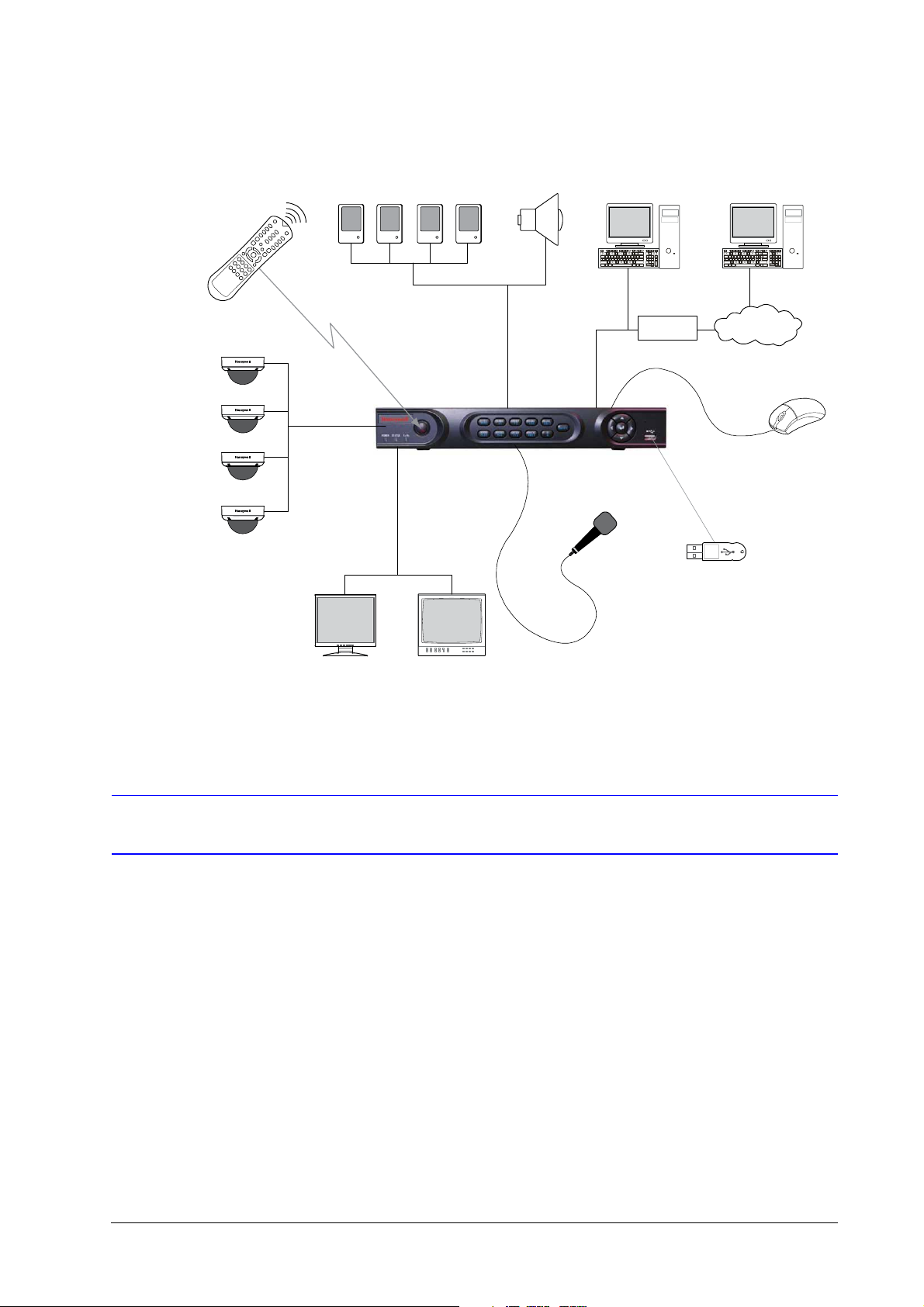
Connect your HRG DVR as shown in Figure 1-1.
800-12005 - A - 06/2012
Page 16
16 | Performance Series DVR User Guide
IR Remote
Control
Alarm Sensors
Alarm Out
Alarm Input/Output
Web Browser Multi-site
Software
Router
Internet
Analog
Cameras
HRG4 DVR
USB Mouse
Support
Microphone
USB Flash Drive
to back up video
clips
Video In
Video Out
Main Monitor
VGA
Spot Monitor
(BNC)
Figure 1-1 System Diagram (HRG4 DVR shown)
Operating the HRG DVR
You can use the following tools to navigate and operate your HRG DVR.
Front Panel
www.honeywellvideo.com
• the front panel controls (see Front Panel on page 16)
• the IR (Infrared) remote (see Using the IR Remote Control on page 19)
• a mouse (see Using a USB Mouse on page 20)
• the virtual keyboard (see Using the Virtual Keyboard on page 21)
Familiarize yourself with the front panel controls for your HRG DVR.
Page 17
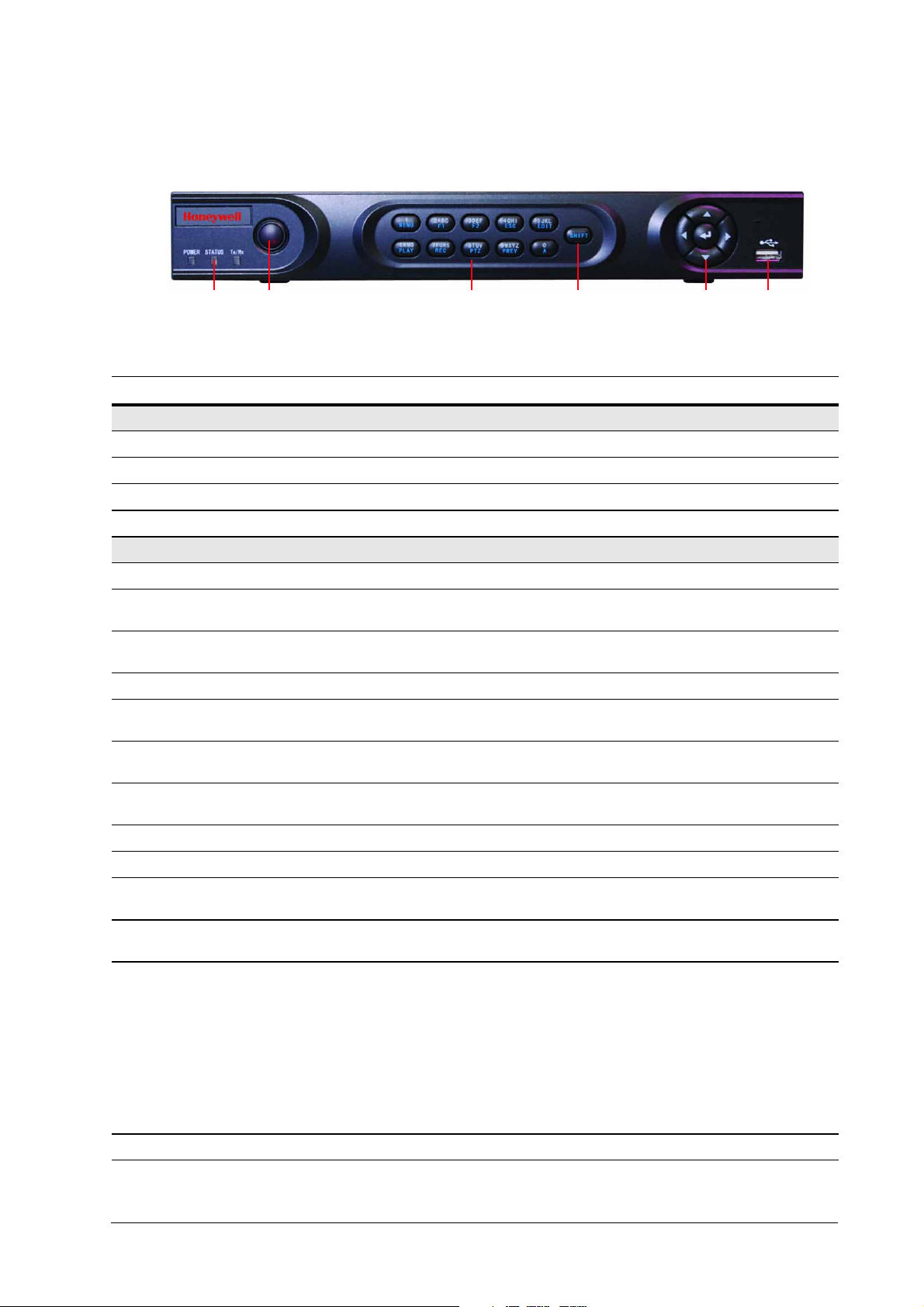
HRG4 Front Panel
12 334 56
Figure 1-2 HRG4 Front Panel
Table 1-1 HRG4 Front Panel Controls and Indicators
Position Control/Indicator Function
1 Status Indicators
POWER Turns green when the HRG DVR is on.
STATUS Illuminates when the compound key switches to numeric/letter input mode.
Tx/Rx Flickers green when the network connection is functioning normally.
2 IR Receiver Sensor for IR Remote Controller.
3 Compound Buttons
Introduction | 17
1/MENU Enter number “1”; Access the main menu.
2/ABC/F1 Enter number “2” or letters “A”, “B”, “C”; The F1 button when used in a list field will
select all items on the list. In PTZ Control mode, it will turn on/off PTZ light.
3/DEF/F2 Enter number “3” or letters “D”, “E”, “F”; The F2 button is used to cycle through tab
pages. It will also bring up the Channel and OSD Position settings.
4/GHI/ESC Enter number “4” or letters “G”, “H”, “I”; Exit and back to the previous menu.
5/JKL/EDIT Enter number “5” or letters “J”, “K”, “L”; Delete characters before cursor; Select the
check box and ON/OFF switch; Start/stop record clipping in playback.
6/MNO/PLAY Enter number “6” or letters “M”, “N”, “O”; Playback, for direct access to playback
interface.
7/PQRS/REC Enter number “7” or letters “P”, “Q”, “R”, “S”; Manual record, for direct access to
manual record interface; manually enable/disable record.
8/TUV/PTZ Enter number “8” or letters “T”, “U”, “V”; Access to PTZ control interface.
9/WXYZ/PREV Enter number “9” or letters “W”, “X”, “Y”, “Z”; Multi-camera display in live view.
0/A Enter number “0”; Switch between input methods (upper and lowercase alphabet,
symbols and numeric input).
4SHIFT Switches the compound keys functions from inputting the numeric/letter values to
the functional controls.
5 Control Buttons Directional buttons: In menu mode, the direction buttons are used to navigate
between different fields and items and select setting parameters. In playback mode,
the Up and Down buttons are used to speed up and slow down record play, and the
Left and Right buttons are used to select the recording 30s forwards or backwards.
In Live View mode, these buttons can be used to cycle through channels.
Enter: The Enter button is used to confirm selection in the Menu mode; or used to
select check box fields and ON/OFF switch. In playback mode, it can be used to
play or pause the video. In single-frame play mode, pressing the Enter button
advances the video by a single frame. And in auto sequence live view mode, the
buttons can be used to pause / resume auto sequence.
6 USB Port Connection for a USB mouse or USB flash memory device.
800-12005 - A - 06/2012
Page 18
18 | Performance Series DVR User Guide
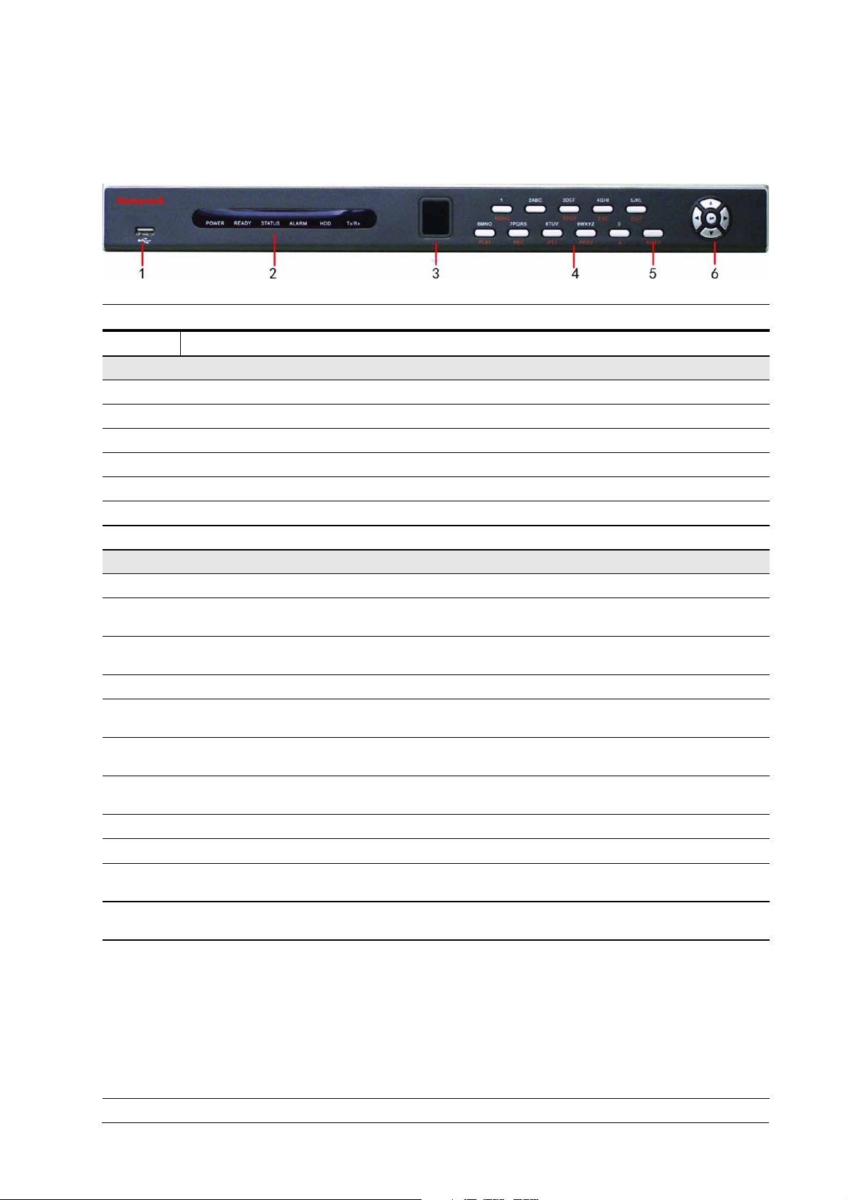
HRG8 and HRG16 Front Panel
Figure 1-3 HRG8 and HRG16 Front Panel
Position Button/Indicator Function
1 USB Port
2 Status Indicators
POWER Turns green when the HRG DVR is on.
READY Turns green when the device is running normally.
STATUS Illuminates when the compound key switches to numeric/letter input mode.
ALARM Turns red when there is a sensor alarm occurring.
HDD Flickers red when the HDD is reading or writing.
Tx/Rx Flickers green when the network connection is functioning normally.
3 IR Receiver Sensor for IR Remote Controller.
4 Compound Buttons
1/MENU Enter number “1”; Access the main menu.
2/ABC/F1 Enter number “2” or letters “A”, “B”, “C”; The F1 button when used in a list field will
3/DEF/F2 Enter number “3” or letters “D”, “E”, “F”; The F2 button is used to cycle through tab
4/GHI/ESC Enter number “4” or letters “G”, “H”, “I”; Exit and back to the previous menu.
5/JKL/EDIT Enter number “5” or letters “J”, “K”, “L”; Delete characters before cursor; Select the
6/MNO/PLAY Enter number “6” or letters “M”, “N”, “O”; Playback, for direct access to playback
7/PQRS/REC Enter number “7” or letters “P”, “Q”, “R”, “S”; Manual record, for direct access to
8/TUV/PTZ Enter number “8” or letters “T”, “U”, “V”; Access to PTZ control interface.
9/WXYZ/PREV Enter number “9” or letters “W”, “X”, “Y”, “Z”; Multi-camera display in live view.
Connection for a USB mouse or USB flash memory device.
select all items on the list. In PTZ Control mode, it will turn on/off PTZ light.
pages. It will also bring up the Channel & OSD Position settings.
check box and ON/OFF switch; Start/stop record clipping in playback.
interface.
manual record interface; manually enable/disable record.
0/A Enter number “0”; Switch between input methods (upper and lowercase alphabet,
5SHIFT Switches the compound keys functions from inputting the numeric/letter values to
6 Control Buttons Directional buttons: In menu mode, the direction buttons are used to navigate
symbols and numeric input).
the functional controls.
between different fields and items and select setting parameters. In playback mode,
the Up and Down buttons are used to speed up and slow down record play, and the
Left and Right buttons are used to select the recording 30s forwards or backwards.
In Live View mode, these buttons can be used to cycle through channels.
Enter: The Enter button is used to confirm a selection in the Menu mode; or used
to select check box fields and the ON/OFF switch. In playback mode, it can be used
to play or pause the video. In single-frame play mode, pressing the Enter button
advances the video by a single frame. And in auto sequence live view mode, the
buttons can be used to pause / resume auto sequence.
www.honeywellvideo.com
Page 19
Using the IR Remote Control
See HRG4 Front Panel on page 17 and HRG8 and HRG16 Front Panel on
page 18 for more about front panel controls.
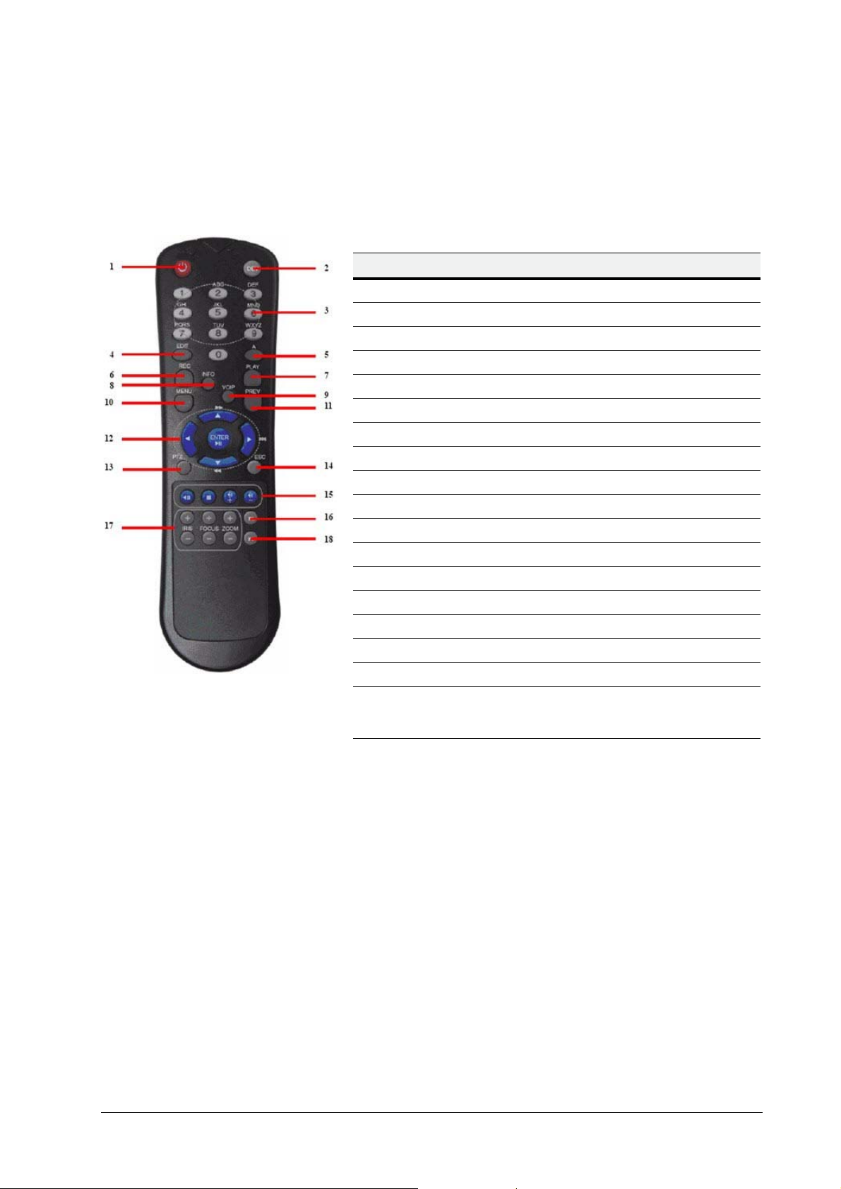
Table 1-2 IR Remote Control
# Button Function
1POWER Turn On/Off the HRG DVR.
2DEV Enable/Disable Remote Control
3 Alphanumerics Same as front panel
4EDIT Same as JKL/EDIT on front panel.
5A Same as 0/A on front panel.
6REC Same as 7/PQRS/REC on front panel.
7PLAY Same as 6/MNO/PLAY on front panel.
8INFO Reserved.
9VOIP Same as 2/ABC/F1 on front panel.
10 MENU Same as 1/MENU on front panel.
11 PREV Same as 9/WXYZ/PR EV on front panel.
12 DIRECTION/ENTER Same as on front panel.
13 PTZ Same as 8/TUV/PTZ on front panel.
14 ESC Same as ESC on front panel.
15 RESERVED Reserved.
16 F1 Same as 2/ABC on front panel.
17 PTZ CONTROL Buttons Use to adjust the iris, focus, and zoom.
18 F2 The F2 button is used to cycle through tab
pages. It can also be used to enter the
Channel and OSD Position settings.
Your HRG DVR may also be controlled with the IR remote control. Batteries (2 x AAA) must be
installed before operation.
Figure 1-4 IR Remote Control
Introduction | 19
Configuring the IR Remote Control
Aim the remote control at the IR receiver located at the front of the unit to test operation. If there
is no response, try the following steps:
1. Use the front control panel or the mouse to navigate to Menu Settings General
More Settings.
2. Check and remember the HRG DVR ID number. The default ID number is 255. This ID
number is valid for all IR remote controls.
3. Press DEV on the remote.
4. Enter the DVR ID number from step 2.
5. Press ENTER on the IR remote control.
The Status indicator on the front panel should turn green to indicate that the remote control is
operating properly.
800-12005 - A - 06/2012
Page 20

20 | Performance Series DVR User Guide
Using a USB Mouse
A regular 3-button (Left/Right/Scroll-wheel) USB mouse can also be used with this HRG DVR.
Connecting a USB Mouse
• Plug the USB mouse into one of the USB ports on the front panel of the HRG DVR.
The mouse should automatically be detected. If, in a rare case, that the mouse is not detected,
pleased refer to the recommended device list from your provider.
USB Mouse Controls
Table 1-3 Mouse Controls
Control Action Result
Single click Select a menu component, such as a button or an
input field. This is similar to pressing the ENTER
button on the remote/front panel controls.
Double click Switch between single screen and multi-screen
mode in Live View/ Playback mode.
Left button
Right button Single click Shows pop-up menu.
Scroll wheel
Click and drag Click and drag the Left mouse button to control the
pan/tilt of a PTZ camera as well as to vary the
position of the digital zoom area and the camera
OSD. It can also be used to setup the alarm areas.
Scroll up In Live View mode, scrolling up will switch to the
previous screen. In Menu mode, it will move the
selection to the previous item.
Scroll down In Live View mode, scrolling down will switch to the
next screen. In Menu mode, it will move the
selection to the next item.
www.honeywellvideo.com
Page 21
Using the Virtual Keyboard
When a mouse is used to perform a task on the HRG DVR, clicking on a text input field brings
up the Virtual Keyboard.
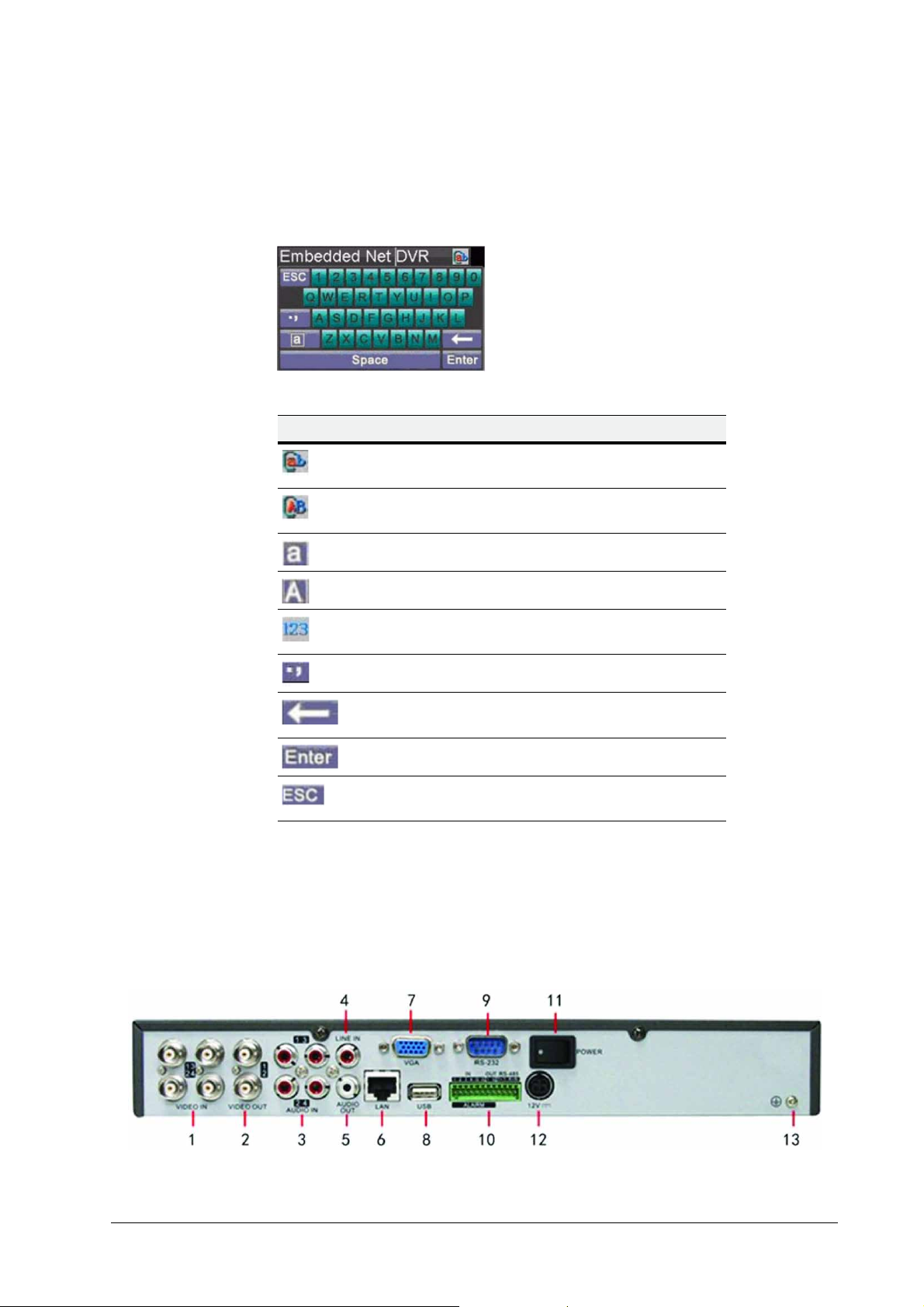
Figure 1-5 Virtual Keyboard
Table 1-4 Virtual Keyboard Controls
Virtual key Name Function
Introduction | 21
Lowercase Indicates that lowercase
input is being used.
Uppercase Indicates that uppercase
input is being used.
Rear Panel
Switch to lowercase Switch to lowercase input.
Switch to uppercase Switch to uppercase input.
Number Indicates that number input is
being used.
Symbols Switch to symbols input.
Backspace Delete a character in front of
the cursor.
Enter Confirm selection.
ESC Exit out of the virtual
keyboard.
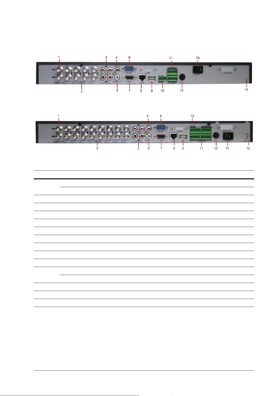
Use these diagrams to make the rear panel connections.
HRG4 Rear Panel Connections and Switches
Figure 1-6 HRG4 Rear Panel Connections and Switches
800-12005 - A - 06/2012
Page 22

22 | Performance Series DVR User Guide
Table 1-5 HRG4 Rear Panel Connections and Switches
Position Connection/Switch Function
1Video In BNC connectors for analog video input.
2Video Out BNC connectors for video output.
3Audio In RCA connectors for analog audio input.
4Line In RCA connector for audio input.
5Audio Out RCA connector for audio output.
6LAN Connector for LAN (Local Area Network).
7VGA DB15 connector for VGA output. Display local video output and menu.
8USB Connector for USB devices.
9 RS-232 Port DB9 connector for RS-232 devices.
Alarm In Connector for alarm input.
10
11 Power Switch for turning On/Off the device.
12 12 V 12 V DC power supply.
Alarm Out Connector for alarm output.
RS-485 Port Connector for RS-485 devices. T+, T- pins connect to PTZ.
13 GND Ground (needs to be connected when HRG DVR star ts up).
www.honeywellvideo.com
Page 23
HRG8 Rear Panel Connections and Switches
HRG16 Rear Panel Connections and Switches
Introduction | 23
Table 1-6 HRG8 and HRG16 Rear Panel Connections and Switches
Position Connection/Switch Function
Main Video Out BNC connectors for analog video input.
1
2Video In BNC connectors for analog video input.
3Audio In RCA connectors for anal og audio input.
4Line In RCA connector for audio input.
5Audio Out RCA connector for audio output.
6 RS-232 Port DB9 connector for RS232 devices.
7VGA DB15 connector for VGA output. Display local video output and menu.
8LAN Connector for LAN (Local Area Network).
9USB Connector for USB devices.
10 RS-485 Port Connector for RS-485 devices. T+, T- pins connect to PTZ.
11
12 12 V 12 V DC power supply.
13 Power Switch for turning On/Off the device.
14 GND Ground (needs to be connected when HRG DVR starts up).
Spot Video Out BNC connectors for spot video out
Alarm In Connector for alarm input.
Alarm Out Connector for alarm output.
800-12005 - A - 06/2012
Page 24

24 | Performance Series DVR User Guide
www.honeywellvideo.com
Page 25

2
Getting Started 2
This chapter covers:
• Starting and shutting down the HRG DVR
• Rebooting and locking the HRG DVR
• Using the Setup Wizard
• Setting the date and time
Starting and Shutting Down the HRG DVR
Proper startup and shutdown procedures are crucial to maintaining the life of your HRG DVR.
Starting the HRG DVR
Note Ensure that the input voltage meets the requirements of the HRG DVR, and that
the GND is grounded.
Note Ensure that the VGA on the HRG DVR rear panel is connected to a display
device, or that the VIDEO OUT port is connected to a monitor. You cannot view
and navigate the menu without being connected to a monitor.
1. Ensure the power supply is plugged into an electrical outlet. It is HIGHLY recommended
that you use an Uninterruptible Power Supply (UPS) in conjunction with the unit.
2. Press the POWER switch on the rear panel. After the power has been started up, the
POWER indicator on the HRG DVR will light green.
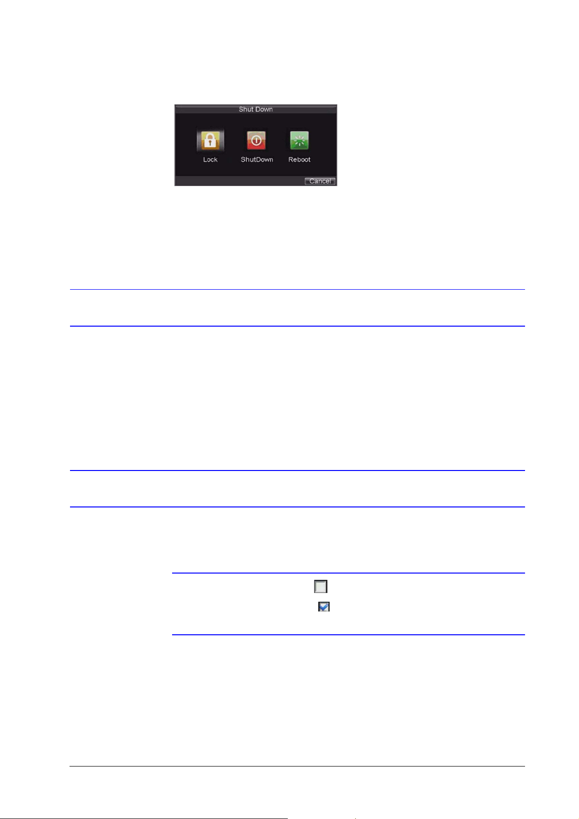
Shutting Down the HRG DVR
1. Click Menu ShutDown to enter the Shutdown menu (see Figure 2-1).
800-12005 - A - 06/2012
Page 26
26 | Performance Series DVR User Guide
Figure 2-1 .Shutdown Menu
2. Click ShutDown.
3. Click Yes in the pop-up window to confirm that you want to shut down the HRG DVR.
Rebooting and Locking the HRG DVR
While in the Shutdown menu, you can also reboot or lock your HRG DVR. Locking your HRG
DVR will return you to the Live View mode, which requires a user name and password to exit out
of it. The Reboot button reboots your HRG DVR.
1. Click Menu
2. Click Lock or Reboot.
ShutDown to enter the Shutdown menu (see Figure 2-1).
Using the Setup Wizard
By default, the Setup Wizard prompt appears when you turn on the HRG DVR (see Figure 2-2).
The Setup Wizard guides you to configure some of the important settings for your HRG DVR.
Note If the check box is cleared , then the Setup Wizard will not run again until the
factory default settings are resumed.
If the check box is selected , then the Setup Wizard will start the next time the
HRG DVR is turned on.
www.honeywellvideo.com
Page 27
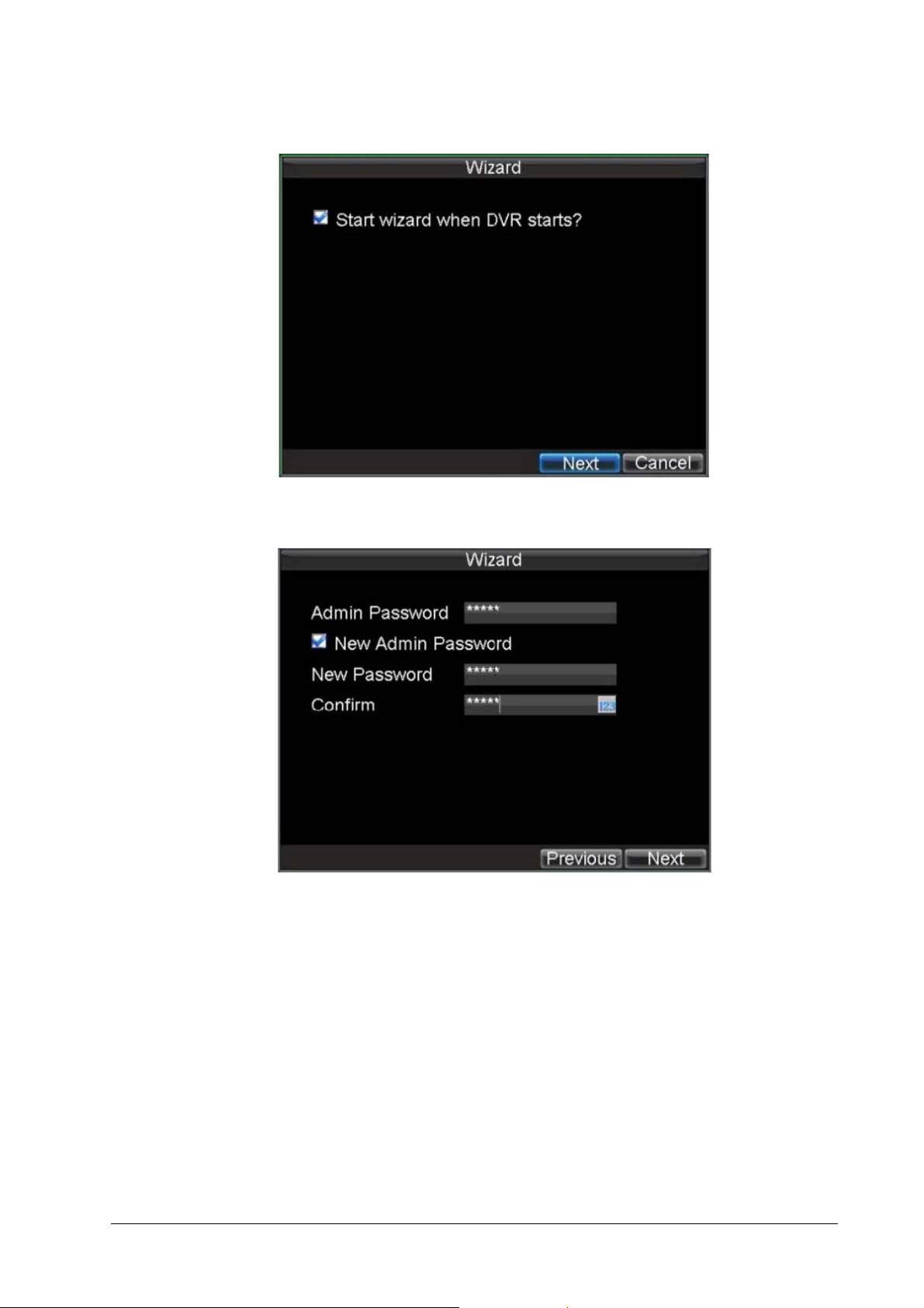
Figure 2-2 Setup Wizard
1. Click Next to open the User Permission window (see Figure 2-3).
Getting Started | 27
Figure 2-3 User Permission Window
2. Navigate to the Admin Password input field. Enter the admin password into the Admin
Password input field. By default, the password is 12345.
3. Select the New Admin Password check box to change the admin password. Enter the
new password and confirm.
4. Click Next to continue to the HDD Management window.
800-12005 - A - 06/2012
Page 28
28 | Performance Series DVR User Guide
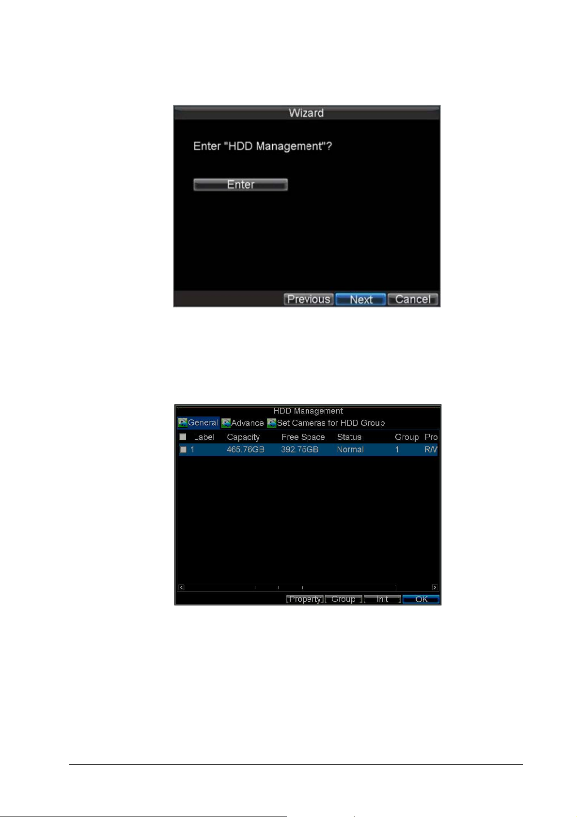
Figure 2-4 Entering the HDD Management Window
5. At the prompt, click Enter to open the HDD Management window (see Figure 2-5).
6. If a new hard drive was recently installed, select the HDD from the list, and then click Init to
initialize it.
Initializing the HDD will format it and remove all data from it.
Figure 2-5 HDD Management Window
7. After the HDD has been initialized, click OK to return to the Setup Wizard.
8. Click Next to continue to the Record Settings window.
www.honeywellvideo.com
Page 29
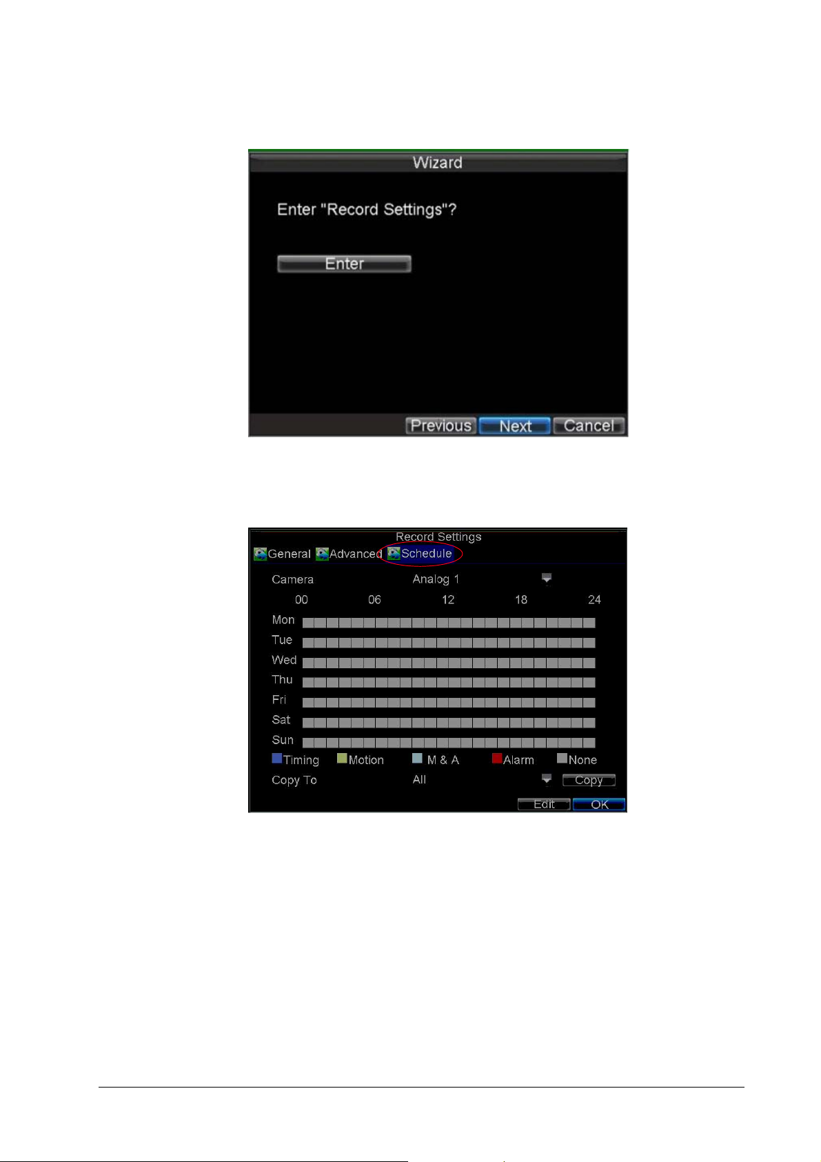
Figure 2-6 Entering the Record Settings Window
Getting Started | 29
9. At the prompt, click Enter to open the Record Settings window (see Figure 2-7).
10. Select the Schedule tab.
Figure 2-7 Schedule Tab
11. Click Edit.
A new recording schedule opens (see Figure 2-8).
800-12005 - A - 06/2012
Page 30
30 | Performance Series DVR User Guide
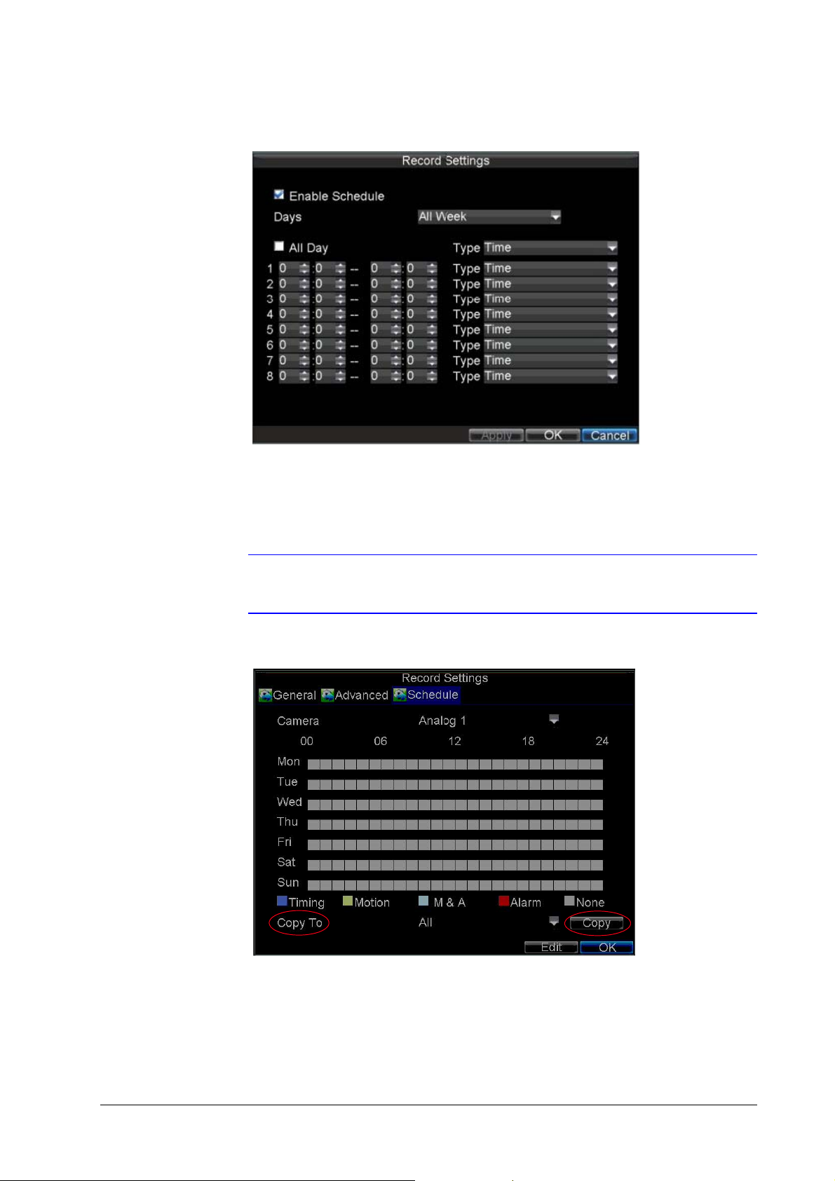
Figure 2-8 Entering a New Recording Schedule
12. Select both the Enable Schedule and All Day check boxes to enable the recording
schedule and allow it to record continuously all day.
13. Click OK to return to the Schedule tab.
Note To copy the schedule to a different channel, select the channel or all under
Copy To, and then click Copy (see Figure 2-9).
Figure 2-9 Copying a Schedule
14. Click Next to continue to the Network Settings window.
www.honeywellvideo.com
Page 31

Figure 2-10 Entering the Network Settings Window
Getting Started | 31
15. At the prompt, click Enter to open the Network Settings window (see Figure 2-11).
Figure 2-11 Network Settings Window
16. Enter the IP Address, Subnet Mask, and Default Gateway.
17. Click OK to return to the Setup Wizard.
18. When you are finished entering settings, click Done to close the Setup Wizard.
This completes the initial setup process. Continue to Setting the Date and Time.
800-12005 - A - 06/2012
Page 32

32 | Performance Series DVR User Guide
Setting the Date and Time
You must set up the system date and time to accurately timestamp recordings and events.
To set up the date and time:
1. Open the General Settings Menu by doing one of the following:
•Press MENU on the remote control or the front panel of the HRG DVR.
• Right-click with the mouse, and then click Menu.
2. Click Settings, and then click General to enter the General Settings menu.
Figure 2-12 Setting the Date and Time
3. Enter the correct date and time in the System Time field.
4. Click Apply to save the settings.
www.honeywellvideo.com
Page 33

3
Live View 3
This chapter describes the Live View on-screen display and how to operate and configure the
Live View display.
On-screen Display in Live View
Live View mode starts automatically when the HRG DVR is turned on. You can return to Live View
mode from any submenu by pressing ESC multiple times.
Live View Icons
Some icons are provided on screen in Live View mode to indicate different camera status. These
icons include:
Main Output
Aux Output
Event Alarm: Indicates video loss, video tampering, motion
detection, or relay alarm.
Record: Indicates the current channel that is recording. The
recording can be started manually or from a schedule, and/or when
a motion detection or alarm event is triggered.
Event Alarm & Record
800-12005 - A - 06/2012
Page 34

34 | Performance Series DVR User Guide
Operating Live View
In Live View mode, you can select the following options:
Display Single Camera • Front Panel/Remote: Use the alphanumeric buttons.
Multi-camera Live View • Front Panel/Remote: Press the PREV button.
Manual Switch • Front Panel/ Remote: Press the left arrow button to
• Mouse: Right-click anywhere in the window, and then
click Single Camera.
• Mouse: Right-click anywhere in the window, and then
click Multi Camera.
access the previous screen. Press the right arrow button
to access next screen.
• Mouse: Right-click anywhere in the window, and then
click Next Screen.
Auto Sequence • Front Panel/Remote: Press the (Enter) button.
Digital Zoom • Mouse: Right-click anywhere in the window, and then
Using the Mouse in Live View
Some functions of the Live View can be quickly accessed by clicking the right mouse button
(see Figure 3-1).
Figure 3-1 Live View Shortcut Menu
• Mouse: Right-click anywhere in the window, and then
click Start Auto-switch.
click Digital Zoom.
www.honeywellvideo.com
Page 35

Live View | 35
Menu items include:
• Single Camera: Switch to a full-screen display of the selected camera by drop-down
submenu.
• Multi Camera: Switch between different multi-camera display modes by drop-down
submenu.
• Next Screen: When displaying less than the maximum number of cameras in Live View,
select this option to switch to the next camera display.
• Playback: Enter Playback mode of the selected camera.
• PTZ: Enter PTZ control mode of the selected camera.
• Digital Zoom: Enter Digital Zoom interface of the selected camera.
• Menu: Enter Main menu.
• Start Auto-switch: Enable multi-camera sequence in Live View mode.
Note The dwell time of the Live View configuration should be set before using Start
Auto-switch function.
Using the Digital Zoom
To use digital zoom in Live View mode:
1. Right-click the mouse in Live View mode, and then click Digital Zoom.
2. Drag the red box to the desired area for zooming.
The zoomed image will be magnified by 4 times (see Figure 3-2).
Figure 3-2 Digital Zoom
800-12005 - A - 06/2012
Page 36

36 | Performance Series DVR User Guide
Configuring the Live View Display
Click Menu Settings Display to enter the Display Settings Menu (see Figure 3-3).
Figure 3-3 Display Settings Menu
Configure the following settings:
• Video Output: Set the video output modes, including VGA, Aux Output, and Main CVBS.
• Mode: Set the live view display mode to be 1×1, 2×2, 3×3, or 4×4.
• Dwell Time: Set the dwell time for camera switching when Start Auto-switch is selected
in Live View.
• Camera Order: Set the camera order for display in the selected mode (see Setting the
Camera Order).
• Enable Audio Output: Enable/disable audio output for the selected video output.
• Event Output Port: Set the port for event output to be VGA, Main CVBS, or Aux Output.
• Event Dwell Time: Set the dwell time for event video display.
www.honeywellvideo.com
Page 37

Setting the Camera Order
The Camera Order settings allow you to set camera sequence in selectable Live View display
mode (see Figure 3-4).
Figure 3-4 Camera Order Settings
Live View | 37
To set the camera order, do the following:
1. Click Menu Settings Display to enter the Display Settings menu.
2. Next to Camera Order, click Set.
3. Select the video output port and the display mode (1×1, 2×2, 3×3, and 4×4 selectable).
4. Use the direction buttons on the front panel of the DVR to move to the display pane for
setting, and then press to confirm the selection.
5. Use the direction buttons on the front panel of the DVR to select the camera you want to
be view in the display pane.
The option '×' indicates that no camera is displayed.
6. Press to confirm the selection.
800-12005 - A - 06/2012
Page 38

38 | Performance Series DVR User Guide
www.honeywellvideo.com
Page 39

4
Recording Settings 4
This chapter explains how to configure recording settings for the HRG DVR, including setting
scheduled recording.
Configuring Recording Settings
There are multiple ways to set up your HRG DVR for recording. These include setting up a
recording schedule, triggering a recording by motion detection and/or a sensor alarm, and
starting a recording manually.
Initializing Recording Settings
1. Click Menu Settings Record to enter the Record Settings menu (see Figure 4-1).
Figure 4-1 General Record Settings Menu
2. Select the camera you want to configure.
800-12005 - A - 06/2012
Page 40

40 | Performance Series DVR User Guide
3. Configure the following settings:
• Encoding Parameters: Set the encoding parameters to be Normal or Event.
• Stream Type: Set the stream type to be Video or Video & Audio.
• Resolution: Set recording resolution at 4CIF, 2CIF, CIF, or QCIF.
• Bit Rate Type: Set the bit rate type to be Variable or Constant.
• Video Quality: Set the recording video quality (6 levels configurable).
• Frame Rate: Set the frame rate of recording.
• Max Bit Rate: Select or customize the maximum bit rate for recording.
4. Next to More Settings, click Set to configure more recording settings (see Figure 4-2).
Figure 4-2 More Record Settings
• Pre-Record: Set the time in seconds to pre-record before the actual recording
begins.
• Post-Record: Set the time in seconds to post-record after the actual recording has
ended.
• Recording Expired Time: Set the expiration time in days for recorded video.
Recorded files after expiration time will be deleted. The actual period for record files
storage is determined by the available HDD space.
• Record Audio: Enable or disable audio recording of the selected camera.
5. Press the 3DEF/F2 button on the front panel of the HRG DVR to select the Advanced tab.
The Advanced Record Settings menu is displayed (see Figure 4-3).
www.honeywellvideo.com
Page 41

Figure 4-3 Advanced Record Settings
Recording Settings | 41
6. Next to Overwrite, select Yes or No to enable or disable the overwrite setting.
Enabling the overwrite setting causes recorded files to be overwritten once the HDD is full.
7. Click Apply, and then click OK to exit the menu.
Scheduling Recording
The Schedule Record Settings menu allows you to set up flexible recording schedules for daily
or weekly recording.
To set up a recording schedule:
1. Click Menu
2. Select the Schedule tab to enter the Schedule Record Settings menu (see Figure 4-4).
Figure 4-4 Schedule Record Settings Menu
Settings Record to enter the Record Settings menu.
3. Select the camera for which you want to configure a recording schedule.
4. Click Edit to enter the Schedule Settings menu.
800-12005 - A - 06/2012
Page 42

42 | Performance Series DVR User Guide
5. Select the Enable Schedule check box.
6. Select the day you want to record or select All Week to record the entire week.
7. Click All Day to enable recording for the entire day, or select different periods for each
day. Up to eight time periods can be scheduled.
Note Scheduled time periods cannot be overlapped.
8. Select the recording type.
The recording type can be selected to scheduled or triggered by motion detection and/or
alarm. For more specific settings about motion detection and alarm recordings, please
refer to Configuring Alarms on page 59.
9. Click OK.
10. Repeat step 3 to step 9 for other cameras, or copy settings from one schedule to the
others under Copy To.
11. Click OK to save the settings.
Note The Event encoding parameters will take effect when motion detection or alarms
are triggered. The Timing encoding parameters will take effect when there no
events are occurring.
Starting a Manual Recording
A manual recording can be enabled at any time by means of the following configuration:
1. Click Menu Manual Record to enter the Manual Record menu (see Figure 4-5).
Figure 4-5 Manual Record Menu
2. Start manual recording by selecting ON or OFF for each camera.
www.honeywellvideo.com
Page 43

Protecting Recorded Files
Two methods are provided to prevent recorded files from being deleted from the HDD or from
being overwritten during cycle recording. You can set the recorded files to be locked or you can
set the HDD that the files reside on to be read-only.
Locking and Unlocking Recorded Files
To lock or unlock a recorded file:
1. Click Menu Video Search to enter the Video Search menu (see Figure 4-6).
Figure 4-6 Video Search Menu
Recording Settings | 43
2. Search for the desired recording by entering search parameters.
Search parameters include Camera ID, Video/File Type, and Start/End Time.
3. Click Search.
A list of recorded files (see Figure 4-7) matching the search parameters are displayed.
800-12005 - A - 06/2012
Page 44

44 | Performance Series DVR User Guide
Figure 4-7 Video Search Result List
4. Select the file you want to lock/unlock.
5. Click Lock to lock the file. If the file is already locked, click Unlock to unlock file.
Locked files are shown with a closed lock, while unlocked files are shown with an opened
lock.
6. Click Cancel to exit the menu.
Setting the Hard Drive to Read-Only
To set a HDD to read-only:
1. Click Menu HDD to enter the HDD Management menu (see Figure 4-8).
Figure 4-8 HDD Management Menu
2. Select the General tab.
3. Select the HDD to set to read-only.
4. Click Property to enter the Property Settings menu (see Figure 4-9).
www.honeywellvideo.com
Page 45

Recording Settings | 45
Figure 4-9 HDD Property Settings Menu
5. Set the HDD Status to Read-only, and then click OK to save the settings.
Note Once set to read-only, the HDD cannot be written to until it is set back to
read/write (R/W).
Note For models installed with one HDD only, when the property is set to read-only,
the recording of the device will be stopped.
800-12005 - A - 06/2012
Page 46

46 | Performance Series DVR User Guide
www.honeywellvideo.com
Page 47

5
Playback Panel
Playback Control
Panel
Playback 5
This chapter describes the playback controls and the various methods of playing back recorded
video, including playback from a search and playing back frame-by-frame.
Video Playback
The Client application allows all users to play back record files of the specified period.
Multi-camera simultaneous playback is supported.
Playback Interface
Multiple toolbar and buttons are provided on the Playback interface to control the video
playback (see Figure 5-1).
Figure 5-1 Playback Interface
The Playback Control panel (see Figure 5-2), provides various control buttons for video
playback.
800-12005 - A - 06/2012
Page 48

48 | Performance Series DVR User Guide
Figure 5-2 Playback Control Panel
Note A blue bar refers to the Normal recording (scheduled, manual), while the red
bar indicates Event recording.
Playback by Search
To play back record files by video search:
1. Click Menu
2. Set the search parameters by selecting which cameras to search, the video type, the file
type, and the start and end times (see Figure 5-3).
Figure 5-3 Video Search Menu
Video Search to enter the Video Search menu.
3. Click Play to start playback of all files found, or click Search to see a list of search results.
4. Select the file you want to play back, and then press Play.
www.honeywellvideo.com
Recorded files will automatically be played back in the Playback interface (see Figure 5-4).
Page 49

Figure 5-4 Playback Interface
Playback | 49
Playback in Live View Mode
The Client application also allows you to play back recorded files in Live View mode.
To play back by channel in Live View mode:
1. Right-click on the desired channel, and then click Playback.
Recorded video from the selected channel will start playing back in the Playback window.
An Attention message will appear if there are no recordings found in the previous five
minutes.
2. Optionally, you can select additional channels for play back from the channel list on the
right side of the Playback interface (see Figure 5-5).
Figure 5-5 Playback Interface
800-12005 - A - 06/2012
Page 50

50 | Performance Series DVR User Guide
Multi-camera Playback
1. Select the cameras from the list for which you want simultaneous playback.
2. Click to stop the ongoing video playback.
3. Click to start multi-camera simultaneous playback.
Note
• Up to 16 cameras can be played back simultaneously.
• The camera list operation is accessible by mouse only. Please do not
• If the camera numbered the lowest among the multiple cameras selected for
• The video for simultaneous playback by multiple cameras selected from the
operate by front panel.
simultaneous playback provides no recorded files for the current day
selected on the calendar, then the warning message Playback failed
will be displayed on the screen.
camera list refers to the all-day recorded files of the selected day.
Playback by System Log
To play back video from the System Log:
1. Click Menu Maintenance Log Search to enter the Log Search menu (see
Figure 5-6).
Figure 5-6 Log Search Menu
2. Set Major Type to Information, set Minor Type to Start Record or End Record, and then
3. Click Search.
4. Select the video log to play back, and then click Play.
www.honeywellvideo.com
select the Start Time and End Time.
A list of search results is displayed.
The selected recording will begin to play in the Playback interface.
Page 51

Playback Frame-by-Frame
To play back frame-by-frame in the Playback interface:
Using a Mouse
1. Click Slow Forward on the Playback Control Panel until the speed changes to single
frame.
2. Click Pause to advance the video frame by frame.
Using the Front Panel/Remote Control
1. Press the down arrow to change the playback speed to single frame.
2. Press (Enter) to advance the video frame by frame.
Digital Zoom
To use digital zoom in Playback mode:
1. Right-click the mouse in Playback mode.
2. Click Digital Zoom in the drop-down submenu.
3. Drag the red box to the desired area for zooming.
The zoomed image will be magnified by 4 times (see Figure 5-7).
Playback | 51
Figure 5-7 Digital Zoom in Playback Mode
800-12005 - A - 06/2012
Page 52

52 | Performance Series DVR User Guide
www.honeywellvideo.com
Page 53

6
Backup 6
This chapter describes how to back up recorded files, including exporting files and video clips.
Backing Up Recorded Files
Recorded files can be backed up to various devices, such as USB flash drives, USB hard drives,
or a DVD writer.
Exporting Files
To export recorded files:
1. Click Menu Video Export to enter the Record Backup menu (see Figure 6-1).
Figure 6-1 Record Backup Menu
2. Select the desired parameters to search for recorded files to export.
3. On the toolbar, click Export.
A list of video search results is displayed (see Figure 6-2).
800-12005 - A - 06/2012
Page 54

54 | Performance Series DVR User Guide
Figure 6-2 Video Search Results
4. Select the recorded files you want to export. You can also click Play to confirm the
recorded file you want to export.
The size of the currently selected files is displayed at the lower-left corner of the window.
5. Click Next to enter the Export menu (see Figure 6-3).
Figure 6-3 Export Menu
6. Select the device to which the record file is to be exported from drop-down list (USB Flash
7. If the backup device is not recognized:
8. Click Start to begin the backup process (see Figure 6-4).
www.honeywellvideo.com
Drive, USB HDD, DVD Writer).
•Click Refresh.
• Reconnect the device.
• Check for compatibility from vendor (see Troubleshooting the HRG DVR on page 113).
Page 55

Backup | 55
Figure 6-4 Backup Progress Screen
9. After the backup process has completed (Figure 6-5), select a file from your device and
click Play to verify that it has been exported successfully.
Figure 6-5 Export Successful Screen
Note Video Player software will automatically be copied to the device that the recorded
files were exported to.
Exporting Video Clips
You can select video clips to export directly in Playback status. A maximum of 30 clips can be
selected for each channel.
800-12005 - A - 06/2012
Page 56

56 | Performance Series DVR User Guide
Exporting Video Clips Using the Mouse
To export video clips during Playback using the mouse:
1. Enter the Playback interface (see Video Playback on page 47).
2. Click Start/Stop Clip on the Playback Control Panel (see Figure 5-2), and select the start
and end of the video clip during playback. Repeat for additional clips.
3. Click Quit Playback to exit the Playback interface. You are then prompted to save the
clips (see Figure 6-6).
Figure 6-6 Save Video Clips Prompt
4. Click Yes to enter the Backup interface, or click No to exit the Playback interface.
5. In the Backup interface, click Start to begin the backup process.
Exporting Video Clips Using the Front Panel/Remote
To export video clips during Playback using the Front Panel/Remote:
1. Enter the Playback interface (See Video Playback on page 47).
2. During playback, press Edit to mark the start of the clip.
3. Press Edit again to mark the end of the clip.
4. Repeat steps 2 and 3 for additional clips.
5. Press the ESC button to exit the Playback interface. You will then be prompted to save the
clips (see Figure 6-6).
6. Click Yes to enter the Backup interface, or click No to exit the Playback interface.
7. In the Backup interface, click Start to begin the backup process.
Managing Backup Devices
To manage backup devices, you must first be in the Export menu (see Figure 6-7). The Export
menu can be accessed by following the steps shown in the section Exporting Files.
www.honeywellvideo.com
Page 57

Figure 6-7 Export Menu
From the Export menu, you can select the following options:
• New Folder: Create a new folder on the export device.
• Delete: Delete a file or folder from the export device.
• Play: Play the selected video file on the export device.
• Format: Format the export device.
• Erase: Erase files from a re-writable CD or DVD.
Backup | 57
800-12005 - A - 06/2012
Page 58

58 | Performance Series DVR User Guide
www.honeywellvideo.com
Page 59

7
Alarm Settings 7
This chapter describes how to configure the HRG DVR to detect and respond to alarms.
Configuring Alarms
Motion Detection Alarm
To configure Motion Detection recording, do the following:
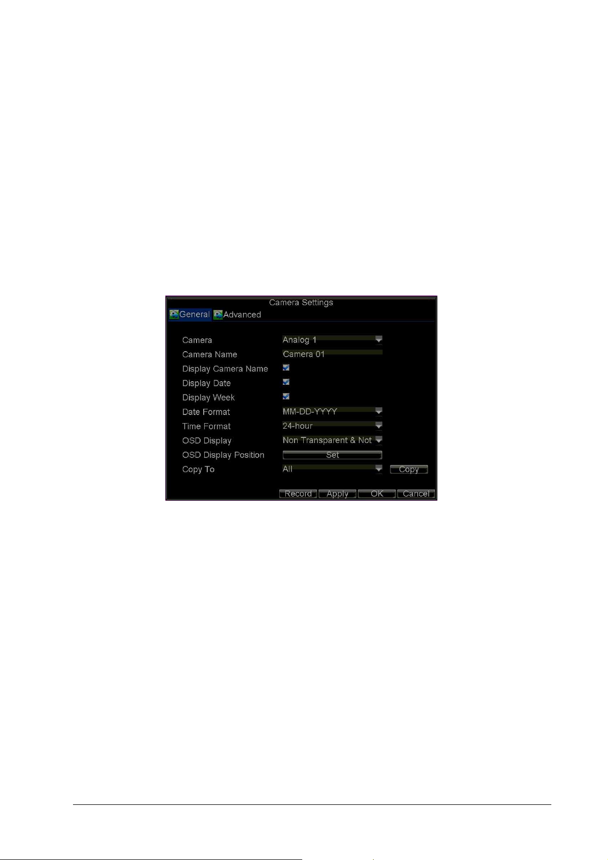
1. Click Menu Settings Camera to enter the Camera Settings menu (see Figure 7-1).
Figure 7-1 Camera Settings Menu
2. Select the Advanced tab to enter the Advanced Camera Settings menu (see Figure 7-2).
800-12005 - A - 06/2012
Page 60

60 | Performance Series DVR User Guide
Figure 7-2 Advanced Camera Settings - Motion Detection
3. Select the Motion Detection check box, and then click Area Settings to enter the Motion
Detection Area Settings interface.
4. Mask the Motion Detection area by dragging the grid with your mouse (see Figure 7-3).
The maximum area can be set to full screen. You can also use the EDIT and direction
buttons on the front panel of the HRG DVR to configure the Motion Detection area.
Figure 7-3 Motion Detection Area Settings Interface
5. Right-click anywhere in the window or press MENU on the front panel of the DVR to set the
www.honeywellvideo.com
Motion Detection Sensitivity (see Figure 7-4). The higher the value, the higher the
sensitivity level.
Page 61

Alarm Settings | 61
Figure 7-4 Motion Detection Sensitivity Settings
6. Click OK to return to the Motion Detection Area Settings interface.
7. Right-click anywhere in the window, and then click Exit to return to the Advanced Camera
Settings menu.
8. Click Handle to enter the Exception Handle menu (see Figure 7-5).
Figure 7-5 Exception Handle Menu
9. Select cameras to trigger for recording when motion is detected by selecting the check
boxes under the desired cameras.
10. Select the Schedule tab to set when you want motion detection to be enabled (see
Figure 7-6). The schedule can be set for all week or any day of the week, with up to eight
time periods per day.
800-12005 - A - 06/2012
Page 62

62 | Performance Series DVR User Guide
Figure 7-6 Schedule Settings
Note After you have configured the schedule, the HRG DVR must be restarted for the
new settings to take effect.
11. Select the Handle tab to configure exceptions handling (see Figure 7-7). Exception trigger
options are described in Understanding Exception Trigger Options on page 71.
Figure 7-7 Handle Settings
12. Click OK to save the settings for the selected camera.
You can now add a schedule to start recording when motion is detected (see Scheduling
Recording on page 41).
Sensor Alarm Settings
Recordings can be triggered from an external relay alarm device.
To set up sensor alarms:
1. Click Menu Settings Alarm to enter the Alarm Settings menu (see Figure 7-8).
www.honeywellvideo.com
Page 63

Figure 7-8 Alarm Settings Menu
Alarm Settings | 63
2. Select the Alarm Input Number, and then click Set to enter the Alarm Input Settings menu
(see Figure 7-9).
Figure 7-9 Alarm Input Settings Menu
3. Set Type to Normally Opened (N.O) or Normally Closed (N.C).
4. Select the Setting check box, and then click Handle to enter the Alarm Input Handle menu
(see Figure 7-10).
800-12005 - A - 06/2012
Page 64

64 | Performance Series DVR User Guide
Figure 7-10 Alarm Input Handle Menu
5. Select the Triggered Camera tab.
6. Select cameras to trigger for recording when an alarm occurs by selecting the check
boxes under the desired cameras (see Figure 7-10).
You can select a PTZ camera to link with the alarm input and then set the call up of preset,
patrol, and pattern for alarm-linked actions.
7. Click OK to save the settings.
8. You can now add a schedule to start recording when an alarm is triggered (see
Scheduling Recording on page 41).
Alarm outputs can also be configured in the Alarm Settings menu.
To set up an Alarm Output:
1. Select the Alarm Output tab to enter the Alarm Output interface (see Figure 7-11).
Figure 7-11 Alarm Output Interface
2. Select the output you want to configure, and then click Set to enter the settings page for
www.honeywellvideo.com
the selected channel (see Figure 7-12).
Page 65

Figure 7-12 Alarm Output Settings
Alarm Settings | 65
3. Configure the settings for the selected output.
4. Click OK to save the settings.
Note If Hold For is set as Manually Stop, the alarm will only stop when you manually
turn it off (see Manual Alarm Triggering).
Manual Alarm Triggering
You can trigger alarm outputs manually through the Manual Alarm menu.
To trigger alarm outputs manually:
1. Click Menu
Figure 7-13 Manual Alarm Menu
Manual Alarm to enter the Manual Alarm menu (see Figure 7-13).
800-12005 - A - 06/2012
Page 66
66 | Performance Series DVR User Guide
2. Configure the following settings in the Manual Alarm menu:
• Trigger: Select an alarm from the list and click Trigger to trigger its output.
• Trigger All: Trigger all alarm outputs at once.
• Clear All: Stop all alarm outputs at once.
3. Click OK to save the settings.
Video Loss Detection
The DVR can be set up to detect video loss and trigger an action.
To set up video loss detection:
1. Click Menu
Figure 7-14 Camera Settings Menu
Settings Camera to enter the Camera Settings menu (see Figure 7-14).
2. Select the Advanced tab to enter the Advanced Camera Settings menu.
3. Select the camera to be configured with video loss detection.
4. Select the Video Loss Detection check box to enable this feature (see Figure 7-15).
www.honeywellvideo.com
Page 67

Alarm Settings | 67
Figure 7-15 Advanced Camera Settings - Video Loss Detection
5. Next to Video Loss Detection, click Handle to enter the Exception Handle menu.
6. Select the Schedule tab to set when you want video loss detection to be enabled (see
Figure 7-16). The schedule can be set for all week or any day of the week, with up to eight
time periods per day.
Figure 7-16 Schedule Settings
Note After you have configured the schedule, the HRG DVR must be restarted for the
new settings to take effect.
7. Select the Handle tab to configure exceptions handling (see Figure 7-17). Exception
trigger options are described in Understanding Exception Trigger Options on page 71.
800-12005 - A - 06/2012
Page 68

68 | Performance Series DVR User Guide
Figure 7-17 Handle Settings
8. Click OK to save the settings.
9. Repeat step 3 to step 8 to configure settings for other channels.
Video Tampering Detection
The video tampering can also be detected and set to trigger an action on your DVR.
Note The video tampering detection area is in full-screen mode by default and cannot
be configured.
To set up video tampering detection:
1. Click Menu Settings Camera to enter the Camera Settings menu (see Figure 7-18).
Figure 7-18 Camera Settings Menu
2. Select the Advanced tab to enter the Advanced Camera Settings menu.
3. Select the camera to be configured with video tampering detection.
4. Select the Tamper Detection check box to enable this feature (see Figure 7-19).
www.honeywellvideo.com
Page 69

Figure 7-19 Advanced Camera Settings - Tamper Detection
Alarm Settings | 69
5. Next to Tamper Detection, click Handle to enter the Exception Handle menu.
6. Select the Schedule tab to set when you want video tampering detection to be enabled
(see Figure 7-20). The schedule can be set for all week or any day of the week, with up to
eight time periods per day.
Figure 7-20 Schedule Settings
Note After you have configured the schedule, the HRG DVR must be restarted for the
new settings to take effect.
7. Select the Handle tab to configure exceptions handling (see Figure 7-21). Exception
trigger options are described in Understanding Exception Trigger Options on page 71.
800-12005 - A - 06/2012
Page 70

70 | Performance Series DVR User Guide
Figure 7-21 Handle Settings
8. Click OK to save the settings.
9. Repeat step 3 to step 8 to configure settings for other channels.
Exception Settings
The exception setting allows the DVR to alert you when irregular events occur. These events
include:
• HDD Full: All installed hard drives are full.
• HDD Error: Errors occurred during writing of the hard drive(s), no hard drive is installed, or
the hard drive(s) failed to initialize.
• Network Disconnected: Disconnected network cable.
• IP Conflict: Conflict in IP address setting.
• Illegal Login: Incorrect user ID or password used.
• Video Output Standard Mismatch: Video output standards do not match each other.
To set exceptions:
1. Click Menu
2. Under Exception Type, select the exception that you want to configure.
3. Select triggering options (see Figure 7-22).
Settings Exception to enter the Exception menu.
www.honeywellvideo.com
Page 71

Figure 7-22 Exception Menu
Understanding Exception Trigger Options
When setting up exception handles for such features as motion detection and relay alarms, you
can select triggering options to alert you of these exceptions.
Alarm Settings | 71
The triggering options include:
• Pop-up Image on Monitor: When an alarm is triggered, the local monitor (VGA or BNC
monitor) will display an image in Live View mode. This alarm can be configured under the
Popup Alarm Image handle method. For alarms that are triggered simultaneously, images
will be displayed one at a time every 10 seconds (default dwell time). A different dwell time
can be set by going to Menu
stops, cycling of the images will also stop and you will be returned to the Live View screen.
• Audio Warning: Trigger an audible beep when exception is detected.
• Notify Surveillance Centre: Sends a signal to remote alarm host when exception is
detected (see Configuring Remote Alarm Host Settings on page 77).
• Trigger Alarm Output: Trigger an alarm output when an exception is detected. Alarm
output can be configured by following the steps listed in Sensor Alarm Settings.
Settings Display Dwell Time. Once the alarm
800-12005 - A - 06/2012
Page 72

72 | Performance Series DVR User Guide
www.honeywellvideo.com
Page 73

8
Network Settings 8
This chapter covers how to configure network settings.
Configuring Network Settings
The network settings must be configured if the HRG DVR is used for monitoring over a network.
Configuring General System Settings
To configure the general network settings:
1. Click Menu Settings Network to enter the Network Settings menu (see Figure 8-1).
Figure 8-1 Network Settings Menu
2. Select the General tab. Configure the settings on the interface.
800-12005 - A - 06/2012
Page 74

74 | Performance Series DVR User Guide
3. If you want to configure your own settings, enter the settings for:
• IP Address: IP address you would like to use for your HRG DVR.
• Subnet Mask: Subnet Mask of network.
• Default Gateway: IP address of your Gateway. Typically the IP address of your router.
• Preferred/Alternate DNS Server: The preferred and alternate Domain Name System
(DNS) Server to be used with your HRG DVR.
4. If you have a DHCP server running and would like your DVR to automatically obtain an IP
address and other network settings from that server, select the DHCP check box. You can
check the DHCP status by going to the Network Status tab (see Figure 8-2).
Figure 8-2 Network Status
5. Click OK to save the settings and exit the menu.
Configuring PPPoE Settings
Your DVR also allows for Point-to-Point Protocol over Ethernet (PPPoE) access.
To set up PPPoE access:
1. Click Menu Settings Network to enter the Network Settings menu.
2. Select the Advanced tab to enter the Advanced Network Settings menu (see Figure 8-3).
www.honeywellvideo.com
Page 75

Network Settings | 75
Figure 8-3 Advanced Network Settings Menu
3. Click Set next to PPPOE to enter the PPPoE Settings menu (see Figure 8-4).
Figure 8-4 PPPoE Settings
4. Select the PPPOE check box to enable this feature.
5. Fill in the User Name, Password, and Confirm Password boxes, and then click OK.
PPPOE credentials can be obtained from your network administrator. Once the setup is
completed, your DVR will automatically dial-up into your network after reboot.
6. Click OK to save the settings and exit the menu.
You may be asked to restart your HRG DVR for the settings to take effect. To check on the
status of your PPPoE connection, go to Menu
Network Status tab.
Settings Network and select the
Configuring DDNS
If your DVR is set up to use PPPoE as its default network connection, you can set up Dynamic
DNS (DDNS).
800-12005 - A - 06/2012
Page 76

76 | Performance Series DVR User Guide
To set up DDNS:
1. Click Menu
2. Select the Advanced tab.
3. Next to DDNS, click Set to enter the DDNS settings menu (see Figure 8-5).
Figure 8-5 DDNS Settings Menu
Settings Network to enter the Network Settings menu.
4. Select the DDNS check box to enable this feature.
5. Select the DDNS Type.
Three different DDNS types are selectable: IpServer, PeanutHull, and DynDNS.
• IpServer: Enter the Server Address for IpServer (see Figure 8-5).
• PeanutHull: Enter the User Name and Password obtained from the PeanutHull
website (see Figure 8-6).
• DynDNS: Ent er the Server Address for DynDNS (members.dyndns.org). Under DVR
Domain Name, enter the domain obtained from the DynDNS web site. Then enter the
User Name and Password registered in the DynDNS network.
Figure 8-6 DynDNS Settings
Configuring NTP Server Settings
A Network Time Protocol (NTP) Server can be set up on your HRG DVR to maintain the current
date and time.
www.honeywellvideo.com
Page 77

Network Settings | 77
To set up an NTP server:
1. Click Menu
2. Select the Advanced tab.
3. Next to NTP, click Set to enter the NTP Settings menu (see Figure 8-7).
Figure 8-7 NTP Settings Menu
Settings Network to enter the Network Settings menu.
4. Select the NTP check box to enable this feature.
5. Configure the NTP settings:
• Synchronize Interval: Time in minutes to synchronize with the NTP server.
• NTP Server: Address of the NTP server.
Note The address can be set to the IP address or the domain name. When the domain
name is used, please set the DNS server address.
6. Click OK to save the settings and exit the menu.
Note Time synchronization interval has a range of 0 to 10080 min, normally 7200 min. If
the DVR is used on a public network, you should use an NTP server that has a
time synchronization function, such as the server at the National Time Center (IP
Address: 210.72.145.44). If the DVR is set up in a more customized network, NTP
software can be used to establish an NTP server used for time synchronization.
Configuring Remote Alarm Host Settings
With a remote alarm host set, the HRG DVR will send a signal to the host when an alarm is
triggered. The remote alarm host must have the Network Video Surveillance software installed.
To set up a remote alarm host:
1. Click Menu
2. Select the Advanced tab.
3. Next to Host/Others, click Set to enter the Host/Others menu (see Figure 8-8).
Settings Network to enter the Network Settings menu.
800-12005 - A - 06/2012
Page 78

78 | Performance Series DVR User Guide
Figure 8-8 Host/Others Menu
4. Enter the Alarm Host IP and Alarm Host Port.
Alarm Host IP is the IP of the remote PC that has the Network Video Surveillance software
installed. The Alarm Host Port must be the same as software's alarm monitor port (default
port is 7200).
Configuring Multicast
Setting up multicasting solves limitation issues when streaming video through a network access
device. A multicast address spans the Class-D IP range of 224.0.0.0 to 239.255.255.255. It is
recommended to use the IP address range from 239.252.0.0 to 239.255.255.255.
To set up multicasting:
1. Click Menu
2. Select the Advanced tab.
3. Next to Host/Others, click Set to enter the Host/Others menu.
4. Set Multicast IP (see Figure 8-9).
When adding a device to the Network Video Surveillance software, the multicast address
must be the same with the DVR's multicast IP.
Figure 8-9 Host/Others Menu
Settings Network to enter the Network Settings menu.
www.honeywellvideo.com
Page 79

5. Click OK to save the settings and exit the menu.
Configuring Server and HTTP Ports
If you would like to change the server and HTTP ports from the default settings, you can do so
in the Network Settings menu. The default server port is 8000 while the default HTTP port is 80.
To change the default ports:
1. Click Menu Settings Network to enter the Network Settings menu.
2. Select the Advanced tab.
3. Next to Host/Others, click Set to enter the Host/Others menu.
4. Enter new Server Port and HTTP Port (see Figure 8-10).
Figure 8-10 Host/Others Menu
Network Settings | 79
Note The Server Port has a port range of 2000 to 65535 and is used for remote client
software access. The HTTP port is used for remote Internet browser access.
800-12005 - A - 06/2012
Page 80

80 | Performance Series DVR User Guide
www.honeywellvideo.com
Page 81

9
PTZ Control 9
This chapter describes how to configure and use the HRG Performance Series DVR to control
PTZ Dome cameras in your network system.
Navigating the PTZ Menu
PTZ menus can be navigated using either the mouse or the front panel/remote. For quick
access to certain PTZ settings, click the right mouse button in Live View mode, and then click
PTZ to enter PTZ control mode (see Using the Mouse in Live View on page 34). While in PTZ
control mode, right-click anywhere in the window to see the PTZ menu (see Figure 9-1).
Figure 9-1 PTZ Menu
800-12005 - A - 06/2012
Page 82

82 | Performance Series DVR User Guide
Menu items include:
• Camera: Select a PTZ camera.
• Call Preset: Call a PTZ preset.
• Call Patrol: Call a PTZ sequence.
• Call Pattern: Call a PTZ pattern.
• Preset Settings: Enter PTZ preset configuration menu.
• Patrol Settings: Enter PTZ sequence configuration menu.
• Pattern Settings: Enter PTZ pattern configuration menu.
• PTZ Menu: Enter PTZ control menu.
• PTZ Settings: Enter PTZ settings menu.
Configuring PTZ Settings
Settings for a PTZ camera must be configured before it is used. Before proceeding, verify that
the PTZ and RS-485 of the DVR are connected properly.
To configure PTZ settings:
1. Click Menu Settings PTZ to enter the PTZ Settings menu (see Figure 9-2).
Figure 9-2 PTZ Settings Menu
2. Next to Camera, select the channel where PTZ camera is installed.
3. Set the Baudrate, Data Bit, Stop Bit, Parity, Flow Control, PTZ Protocol, and Address.
4. Click OK to save the settings and exit the menu.
www.honeywellvideo.com
Note All setting parameters (baud rate, data bit, stop bit, parity, flow control, PTZ
protocol and address) must be consistent with the PTZ camera connected.
Page 83

Setting PTZ Presets, Patrols and Patterns
2
1
4
567839
The HRG DVR allows you to program presets, patrols, and patterns for a connected PTZ
camera.
Understanding PTZ Controls
The PTZ control panel provides a series of PTZ controls (see Figure 9-3).
Figure 9-3 PTZ Control Panel
PTZ Control | 83
The controls on the panel include:
1. Directional Pad/Auto-scan Buttons: Controls the movements and directions of the PTZ.
The center button is also used to start the auto-scan of the PTZ.
2. Zoom: Used to zoom in and out with the PTZ.
3. Focus: Used to adjust the focus of the PTZ.
4. Iris: Used to open up or close the iris of the PTZ.
5. Speed: Adjusts the movement speed of the PTZ.
6. Light: Turns the PTZ light (if applicable) on and off.
7. Wiper: Turns the PTZ wiper (if applicable) on and off.
8. Zoom In: Instantly zooms the PTZ in.
9. Center: Centers the PTZ.
Customizing Presets
Presets can be set to move your PTZ camera to a desired preset location.
To set up and call custom PTZ presets:
1. Open the PTZ Control panel (Figure 9-3) by selecting PTZ in the right-click menu or by
pressing PTZ on the front panel of the DVR.
2. Click Preset to enter the Preset Management menu.
3. In the Preset Management menu (see Figure 9-4) you can:
• Configure Preset: Use the PTZ control panel to adjust the position of the preset.
Select a Preset number and click Set to save preset location.
• Clear Preset: Select a Preset number and click Clear to delete the preset. You can
also click Clear All to delete all presets.
• Call Preset: Select a Preset and click Call.
800-12005 - A - 06/2012
Page 84

84 | Performance Series DVR User Guide
Figure 9-4 Preset Management Menu
Note Only valid presets can be called and deleted.
Customizing Patrols
Patrols can be programmed to move the PTZ to different key points and make it stay there for a
defined duration before moving on to the next point. The key points are defined by presets
which can be set by following the steps above in Customizing Presets.
To set up and call PTZ patrols:
1. Open the PTZ Control panel (Figure 9-3), by clicking PTZ in the mouse menu or by
pressing PTZ on the front panel of the DVR.
2. Click Patrol to enter the Patrol Management menu (see Figure 9-5).
Figure 9-5 Patrol Management Menu
www.honeywellvideo.com
Page 85

PTZ Control | 85
3. In the Patrol Management menu, you can configure a patrol:
a. Select a Patrol Number to set.
b. Select valid presets (See Customizing Presets), and then click Set to enter the Patrol
Configuration menu. A sequence should have at least two valid presets.
c. Set the KeyPoint No., Duration, and Speed (see Figure 9-6).
The KeyPoint Number determines the order the PTZ will follow when cycling through
the patrol. The Duration refers to the time span to stay at the corresponding keypoint.
The Speed defines the rate at which the PTZ will move to the current preset.
Figure 9-6 Patrol Configuration Menu
4. Click OK to return to the Patrol Management menu and repeat step 2 and step 3 to
configure other keypoints.
5. After all keypoints have been configured, click the defined KeyPoint Number, and then
click Add to complete the setting.
6. Click OK to save the settings and exit the current menu.
To clear a PTZ patrol:
1. In the Patrol Management menu (Figure 9-5), select a valid Patrol Number.
2. Click Clear to delete the patrol.
To call a PTZ patrol:
1. In the Patrol Management menu (Figure 9-5), select a valid Patrol Number.
2. Click Start to call the patrol, and then click Stop to stop the patrol (see Figure 9-7).
800-12005 - A - 06/2012
Page 86

86 | Performance Series DVR User Guide
Figure 9-7 Patrol Management Menu
Customizing Patterns
Patterns can be set up by recording the movement of the PTZ.
To set up and call PTZ patterns:
1. Open the PTZ Control panel (Figure 9-3), by clicking PTZ in the mouse menu or by
pressing PTZ on the front panel of the DVR.
2. Click Pattern to enter the Pattern Management menu (see Figure 9-8).
Figure 9-8 Pattern Management Menu
3. Select a Pattern Number.
4. To record a new pattern, click Run Record to start recording the movements of the PTZ.
5. To run a pattern, click Run Pattern on a valid pattern.
6. Click OK to exit the menu.
www.honeywellvideo.com
Use the PTZ control panel to move the PTZ. The PTZ movements are recorded until Stop
Record is clicked.
The PTZ moves according to the path that was defined until Stop Pattern is clicked.
Page 87

10
Camera Management 10
This chapter covers OSD settings, image settings, and privacy mask settings.
OSD Settings
Use the Camera Management menu to configure on-screen display (OSD) settings. The OSD is
shown in each display during Live View mode and includes the time and date as well as the
camera name.
To configure OSD settings:
1. Click Menu
2. Select the channel to set up the OSD settings in the Camera drop-down list and then click
3. Configure the desired OSD settings (see Figure 10-1).
Settings Camera to enter the Camera Settings menu (see Figure 10-1).
Set.
Figure 10-1 Camera Settings Menu
4. Click Set to modify the OSD display position, including the camera name position and the
date/time display position.
800-12005 - A - 06/2012
Page 88

88 | Performance Series DVR User Guide
Image Settings
Image settings such as the brightness, contrast, saturation and hue can also be adjusted in the
Camera Management menu.
To adjust image settings:
1. Click Menu
2. Select the Advanced tab to enter the Advanced Camera Settings menu (see Figure 10-2).
Figure 10-2 Advanced Camera Settings Menu
Settings Camera to enter the Camera Settings menu (see Figure 10-1).
3. Select the channel for image settings in the Camera drop-down list.
4. Next to Image Settings, click Set.
5. Adjust the image settings (see Figure 10-3).
You can adjust brightness, contrast, saturation, and hue in the menu. The adjustments of
image settings will affect the live images and the recorded images.
Figure 10-3 Image Settings
www.honeywellvideo.com
Page 89

Privacy Mask Settings
You can set up privacy mask to mask off sensitive or private areas in the field of view of a
camera.
To set up a privacy mask:
1. Click Menu
2. Select the Advanced tab to enter the Advanced Camera Settings menu (see Figure 10-4).
Select the channel for privacy mask settings in the Camera drop-down list.
Figure 10-4 Advanced Camera Settings Menu
Settings Camera to enter the Camera Settings menu.
Camera Management | 89
3. Select the Mask check box to enable the feature.
4. Click Area Settings to enter the Area Settings menu.
5. Set the mask area (see Figure 10-5). You can configure up to four areas.
Figure 10-5 Setting Mask Area
6. Click Exit to save the settings and exit the Mask Area Settings interface.
800-12005 - A - 06/2012
Page 90

90 | Performance Series DVR User Guide
www.honeywellvideo.com
Page 91

11
Hard Drive Management 11
This chapter covers how to configure and manage the hard drive(s) of the HRG Performance
Series DVR.
Managing Hard Drives
Initializing Hard Drives
A newly installed hard disk drive (HDD) must be first initialized before it can be used with your
HRG DVR. Initializing the HDD will erase all data on it.
To initialize a HDD:
1. Click Menu HDD to enter the HDD Management menu (see Figure 11-1).
Figure 11-1 HDD Management Menu
2. Select the hard drive (HDD) that you want to initialize.
3. Click Init.
800-12005 - A - 06/2012
Page 92

92 | Performance Series DVR User Guide
4. Click OK to start the initialization process.
After the HDD has been initialized, the status of the HDD will change from Abnormal to
Normal.
Setting HDD Groups
Your HRG DVR can separate multiple HDDs into groups. Video from specified channels can be
recorded to a particular HDD group.
To set up an HDD group:
1. Click Menu HDD to enter the HDD Management menu.
2. Select the HDDs to be added to the group.
3. Click Group to enter the Group Settings menu (see Figure 11-1).
4. Set the HDD Group Number (see Figure 11-2).
Figure 11-2 HDD Group Settings Menu
5. Click OK to save settings and exit the Group Settings menu.
Note By default, all HDDs belong to Group 1.
Setting HDD Status
You can change the behavior of your HDD by changing its status. The status of a HDD can be
set to read-only or read/write (R/W).
Setting an HDD to Read-Only
A HDD can be set to read-only to avoid important recorded files from being overwritten when
the HDD becomes full.
To set a HDD to read-only:
1. Click Menu
2. Select the HDD to be protected.
HDD to enter the HDD Management menu.
www.honeywellvideo.com
Page 93

Hard Drive Management | 93
3. Click Property to enter the Property Settings menu (see Figure 11-3).
Figure 11-3 HDD Property Settings Menu
4. Set HDD Status to Read-Only.
5. Click OK to save the settings and exit the current menu.
Note Once set to read-only, the HDD cannot be written to until it is set back to
Checking HDD Status
You can check the status of the installed HDDs on your HRG DVR at any time.
To check the status of a HDD:
•Click Menu
The status of your HDD is listed under the Status column.
•A Normal or Hibernate status indicates that the HDD is in working order.
• If the status is listed as Abnormal and has already been initialized, the HDD needs to
be replaced. If the HDD is uninitialized, you need to initialize it before it can be used in
your HRG DVR. Please see Initializing Hard Drives on page 91 for further instructions.
Using the SMART Function
You can also view the SMART information of the installed HDD. SMART (Self-Monitoring,
Analysis and Reporting Technology) is a monitoring system for hard disk drives to detect and
report on various indicators of reliability in the hopes of anticipating failures.
read/write (R/W).
Your DVR can be installed with one HDD only; therefore, when the
property is set to read-only, the recording of the device will be stopped.
HDD to enter the HDD Management menu.
To view SMART information of an HDD:
1. Click Menu
Figure 11-4).
Maintenance Log Search to enter the Log Search menu (see
800-12005 - A - 06/2012
Page 94

94 | Performance Series DVR User Guide
Figure 11-4 Log Search Menu
2. Set the Major Type field to Information.
3. Set the Minor Type field to HDD SMART.
4. Enter the desired times in the Start Time and End Time fields.
5. Click Search to begin the log search.
A list of results similar to that of Figure 11-5 are displayed.
Figure 11-5 Log Search Results
6. Select the log item to view and click Details.
www.honeywellvideo.com
A detailed list of SMART information will be displayed (see Figure 11-6).
Page 95

Figure 11-6 HDD SMART Information
Hard Drive Management | 95
You can also click Menu
then select the Advance option to enter the SMART menu (see Figure 11-7). You can enable the
SMART function and view the SMART information as well.
Figure 11-7 HDD SMART Menu
HDD to enter the HDD management menu (see Figure 11-2), and
Configuring HDD Alarms
You can set HDD alarms to trigger when an HDD is uninitialized or in an abnormal state.
To set HDD alarms:
1. Click Menu
Settings Exception to enter the Exception menu (see Figure 11-8).
800-12005 - A - 06/2012
Page 96

96 | Performance Series DVR User Guide
Figure 11-8 Exception Menu, HDD Error
2. Set the Exception Type drop-down list to HDD Error.
3. Select the Trigger Action Output check box. Trigger actions are further explained in
Understanding Exception Trigger Options on page 71.
www.honeywellvideo.com
Page 97

12
HRG DVR Management 12
This chapter describes how to configure system settings and manage user accounts. It also
covers how to update system firmware, restore default settings, and view system information.
Configuring System Settings
Configuring General Settings
Use the General Settings menu to configure general settings such as the system language.
To configure general settings:
1. Click Menu Settings General to enter the General Settings menu (see Figure 12-1).
Figure 12-1 General Settings Menu
2. Select the General tab.
800-12005 - A - 06/2012
Page 98

98 | Performance Series DVR User Guide
3. Configure general settings, including:
• Language: Default language used in all the HRG DVR menus.
• CVBS Output Standard: Video output standard: NTSC and PAL.
• VGA Resolution: VGA output resolution. 1024 × 768/60HZ and 1280 × 1024/60HZ
resolution is selectable.
• Time Zone: Time zone that you want the DVR to use.
• Menu Date Format: Format for date.
• System Time: System time and date.
• Mouse Pointer Speed: Speed of mouse pointer.
• Enable Password: Enable/disable system password.
Note If the video standard is different between the input and the output, you may
notice flickering in Live View mode. After modifying the video standard, please
reboot the DVR to validate the settings.
Configuring Advanced Settings
To configure more advanced system settings:
4. Click Menu Settings General to enter the General Settings menu (see Figure 12-1).
5. Select the More Settings tab to enter the More Settings menu (see Figure 12-2).
Figure 12-2 More Settings Menu
www.honeywellvideo.com
Page 99

HRG DVR Management | 99
6. Configure the following settings:
• Device Name: Name of the HRG DVR used.
• Device No.: Device number of the HRG DVR.
• CVBS Output Brightness: Video output brightness. Level 0 to 63 can be
configurable.
• Transparency: Menu transparency.
• Operation Timeout: Set the timeout time for menu inactivity. For example, if timeout
time was set to five minutes, after five minutes of inactivity in the General Settings
menu, you are returned to the Live View.
• Output Hint: Enable/disable video output hint for main or aux video output.
• Menu Output Mode: Select the menu output mode to Auto, VGA/HDMI or CVBS.
When Auto is selected, the system automatically detects whether the VGA/HDMI or
CVBS interface is connected.
• Input Mode: Set the video input mode to Standard or Gentle.
Setting the RS-232 Port
To configure RS-232 devices to be used with the DVR:
1. Click Menu
Figure 12-3 RS-232 Settings Menu
Settings RS232 to enter the RS-232 Settings menu (see Figure 12-3).
2. Configure the RS-232 settings.
800-12005 - A - 06/2012
Page 100

100 | Performance Series DVR User Guide
3. The RS-232 port can be used in two ways:
• Parameter Control: Connect a PC to the HRG DVR using the PC serial port. You can
then set device parameters using software such as HyperTerminal. The serial port
parameters must be the same as the DVR's when connecting with the PC serial port.
• Transparent Channel: Connect a serial device directly to the HRG DVR. The serial
device will be controlled remotely by the PC through the network and the protocol of
the serial device.
Managing User Accounts
By default your Performance Series DVR is configured with the user name of admin and
password 12345. The Administrator has the authority to add, delete, or configure the user
parameters.
Adding a New User
To add a new user:
1. Click Menu Settings User to enter the User Settings menu (see Figure 12-4).
Figure 12-4 User Settings Menu
2. Click Add to enter the Add User menu (see Figure 12-5).
www.honeywellvideo.com
You can add up to 31 users.
 Loading...