

Page 1
Page 2

Page 3

Warnings
Honeywell
1. Electrical safety
All installation and operation here should conform to local electrical safety
codes.
We assume no liability or responsibility for all the fires or electrical shock
caused by improper handling or installation.
2. Transportation security
Heavy stress, violent vibration or water splash are not allowed during
transportation, storage and installation.
3. Installation
Keep upwards. Handle with care.
Do not connect power to the DVR before completing installation.
Do not place objects on the DVR.
4. Qualified engineers needed
All the examination and repair work should be done by the qualified
service engineers.
We are not liable for any problems caused by unauthorized modifications,
attempted repair or careless operation by human error.
5. Environment
The DVR should be installed in a cool, dry place away from direct sunlight,
inflammable, explosive substances and etc.
6. Accessories
Be sure to use all the accessories recommended by manufacturer.
Unpack Everything
Check that the items received match those listed on the order form and
packing slip. The packing box should include, in addition to this User
Guide:
• One power cable
• One Ethernet cable
• One HDD cables
• One 25-pin alarm converter
• One CD(including DVR manual, client tools)
i
Page 4

Honeywell
• A package of installation fittings
Contact your local retailer as soon as possible if anything is missing in
your package.
Before You Begin
Please read this guide carefully before you install and operate the DVR.
ii
Page 5

Honeywell
Contents
1 About This Document.............................................................................................................1
Overview of Contents .............................................................................................................1
Special Font and Symbols......................................................................................................1
How to Use This Document....................................................................................................2
2 Features and Specifications ...................................................................................................3
Features .................................................................................................................................3
Specifications .........................................................................................................................4
3 Panel Controls........................................................................................................................8
Front Panel.............................................................................................................................8
Rear Panel ...........................................................................................................................11
4 Installation and Connections ................................................................................................13
Check Unpacked DVR..........................................................................................................13
HDD Installation ...................................................................................................................13
Calculate HDD Size ..........................................................................................................13
HDD Installation................................................................................................................14
CD/DVD Burner Installation..................................................................................................15
Desktop and Rack Mounting ................................................................................................15
Desktop Mounting .............................................................................................................15
Rack Mounting..................................................................................................................15
Connecting Power Supply.................................................................................................15
Connections .........................................................................................................................15
Connecting Video Input and Output Devices ....................................................................16
Connecting Audio Input and Audio Output ........................................................................17
Connecting Alarm Input and Alarm Output .......................................................................18
Relay Output Description ..................................................................................................20
RS232...............................................................................................................................21
RS485...............................................................................................................................21
Other Interfaces ................................................................................................................21
5 Overview of Navigation and Controls ...................................................................................22
Login, Logout and Main Menu ..............................................................................................22
Login.................................................................................................................................22
Main Menu ........................................................................................................................23
Logout...............................................................................................................................23
Auto Recovery after Power Failure ...................................................................................24
Replace Battery ................................................................................................................24
Recording Operation ............................................................................................................24
Live Viewing......................................................................................................................24
Manual Recording.............................................................................................................25
Search & Playback ...............................................................................................................26
Calendar ...........................................................................................................................29
Record Setup (Schedule) .....................................................................................................30
i
Page 6

Honeywell
Schedule Menu.................................................................................................................30
Basic Operation ................................................................................................................31
Detect...................................................................................................................................33
Motion Detect....................................................................................................................33
Loss Detect.......................................................................................................................35
Blind Detect ......................................................................................................................36
Alarm Setup and Alarm Activation........................................................................................38
Backup .................................................................................................................................39
PTZ Control and Color Setup ...............................................................................................42
Cable Connection .............................................................................................................42
PTZ Setup.........................................................................................................................42
Preset/Patrol/Pattern/Scan ...................................................................................................44
Preset Setup .....................................................................................................................45
Activate Preset..................................................................................................................46
Patrol Setup (Tour setup)..................................................................................................46
Activate Patrol (tour) .........................................................................................................46
Pattern Setup....................................................................................................................46
Activate Pattern Function..................................................................................................47
Auto Scan Setup...............................................................................................................47
6 Understanding of Menu Operations and Controls ................................................................48
Setting ..................................................................................................................................50
General .............................................................................................................................50
Encode..............................................................................................................................52
Schedule...........................................................................................................................53
RS232...............................................................................................................................53
Network.............................................................................................................................54
Alarm ................................................................................................................................59
Detect ...............................................................................................................................59
Pan/Tilt/Zoom ...................................................................................................................59
Display ..............................................................................................................................60
Default ..............................................................................................................................61
Search..................................................................................................................................61
Advanced .............................................................................................................................62
HDD Management ............................................................................................................62
Alarm Output.....................................................................................................................63
Alarm Input .......................................................................................................................64
Manual Record .................................................................................................................64
Account.............................................................................................................................64
Auto Maintain....................................................................................................................65
TV Adjust ..........................................................................................................................66
Info .......................................................................................................................................67
HDD Info ...........................................................................................................................67
BPS...................................................................................................................................68
Log....................................................................................................................................68
Version..............................................................................................................................69
Online Users .....................................................................................................................69
Shutdown .............................................................................................................................70
ii
Page 7

Honeywell
About Auxiliary Menu ...........................................................................................................71
7 Web Client Operation ...........................................................................................................73
Network Connection .............................................................................................................73
Login and Logout..................................................................................................................73
Go to Real-time Monitor Mode .............................................................................................75
Video (Right Mouse Click Menu Operation) .........................................................................76
Real time Monitor..............................................................................................................77
Multi-camera Preview .......................................................................................................77
Start Dialog .......................................................................................................................77
Playback Control Bar ........................................................................................................77
PTZ Control ......................................................................................................................78
Video Setting ....................................................................................................................78
Network Data Flux ............................................................................................................78
Full Screen........................................................................................................................79
Video Zoom ......................................................................................................................79
Video Windows .................................................................................................................79
Search..................................................................................................................................80
Download..........................................................................................................................80
Configuration ........................................................................................................................82
Load and Save Configuration ...........................................................................................83
General .............................................................................................................................83
Image................................................................................................................................84
Alarm ................................................................................................................................86
Video Detect .....................................................................................................................87
Record ..............................................................................................................................88
Assistant...............................................................................................................................89
User Management ............................................................................................................90
Record Control..................................................................................................................93
Log Information.................................................................................................................93
Date and Time ..................................................................................................................94
System Information...........................................................................................................94
Alarm Prompt....................................................................................................................95
Camera Title .....................................................................................................................96
Upgrade BIOS ..................................................................................................................96
Reboot ..............................................................................................................................97
About WebClient Control ..................................................................................................97
Uninstall WebClient Control..................................................................................................98
iii
Page 8

Page 9

Honeywell
Figures
Figure 3-1 Front Panel ......................................................................................................................8
Figure 3-2 Rear Panel.....................................................................................................................12
Figure 4-1 Connection Sample........................................................................................................16
Figure 4-2 Alarm Input/Output.........................................................................................................19
Figure 4-3 Connection.....................................................................................................................20
Figure 4-4 Relay Output..................................................................................................................20
Figure 5-1 Login ..............................................................................................................................23
Figure 5-2 Main Menu .....................................................................................................................23
Figure 5-3 Logout............................................................................................................................24
Figure 5-4 Shutdown Options .........................................................................................................24
Figure 5-5 Manual Record ..............................................................................................................25
Figure 5-6 Search ...........................................................................................................................27
Figure 5-7 Calendar ........................................................................................................................30
Figure 5-8 SCHEDULE ...................................................................................................................30
Figure 5-9 HDD MANAGEMENT ....................................................................................................32
Figure 5-10 DETECT ......................................................................................................................33
Figure 5-11 Motion Detection..........................................................................................................34
Figure 5-12 Preset ..........................................................................................................................35
Figure 5-13 Motion Detection Region..............................................................................................35
Figure 5-14 Loss Detect..................................................................................................................36
Figure 5-15 Blind Detect .................................................................................................................37
Figure 5-16 Set Period ....................................................................................................................37
Figure 5-17 ALARM ........................................................................................................................38
Figure 5-18 BACKUP ......................................................................................................................40
Figure 5-19 Backup Device.............................................................................................................40
Figure 5-20 Backup in Process .......................................................................................................41
Figure 5-21 PAN/TILT/ZOOM .........................................................................................................42
Figure 5-22 Right Click Menu..........................................................................................................43
Figure 5-23 PAN/TILT/ZOOM Adjust ..............................................................................................43
i
Page 10

Honeywell
Figure 5-24 Direction Arrows ..........................................................................................................44
Figure 5-25 PAN/TILT/ZOOM – Set ................................................................................................44
Figure 5-26 PAN/TILT/ZOOM – Page Switch .................................................................................45
Figure 5-27 PAN/TILT/ZOOM – Preset ...........................................................................................45
Figure 5-28 PAN/TILT/ZOOM – Cruise ...........................................................................................46
Figure 5-29 PAN/TILT/ZOOM – Pattern..........................................................................................46
Figure 5-30 PAN/TILT/ZOOM .........................................................................................................47
Figure 6-1 Main Menu .....................................................................................................................48
Figure 6-2 SETTING .......................................................................................................................50
Figure 6-3 GENERAL......................................................................................................................51
Figure 6-4 ENCODE .......................................................................................................................52
Figure 6-5 Overlay ..........................................................................................................................53
Figure 6-6 RS232............................................................................................................................54
Figure 6-7 NETWORK ....................................................................................................................55
Figure 6-8 IP FILTER ......................................................................................................................56
Figure 6-9 MCAST SET ..................................................................................................................56
Figure 6-10 NTP Setting .................................................................................................................58
Figure 6-11 PAN/TILT/ZOOM .........................................................................................................59
Figure 6-12 DISPLAY......................................................................................................................60
Figure 6-13 DEFAULT ....................................................................................................................61
Figure 6-14 ADVANCED.................................................................................................................62
Figure 6-15 HDD MANAGEMENT ..................................................................................................62
Figure 6-16 Abnormity.....................................................................................................................63
Figure 6-17 ALARM OUTPUT.........................................................................................................64
Figure 6-18 ALARM INPUT.............................................................................................................64
Figure 6-19 ACCOUNT ...................................................................................................................65
Figure 6-20 AUTO MAINTAIN.........................................................................................................66
Figure 6-21 TV ADJUST .................................................................................................................66
Figure 6-22 INFO ............................................................................................................................67
Figure 6-23 HDD INFO ...................................................................................................................67
Figure 6-24 BPS..............................................................................................................................68
ii
Page 11

Honeywell
Figure 6-25 LOG .............................................................................................................................69
Figure 6-26 VERSION.....................................................................................................................69
Figure 6-27 ONLINE USERS ..........................................................................................................70
Figure 6-28 SHUTDOWN................................................................................................................71
Figure 6-29 Right Click Menu..........................................................................................................71
Figure 6-30 COLOR SETTING........................................................................................................72
Figure 7-1 Security Settings............................................................................................................74
Figure 7-2 Web Service ..................................................................................................................74
Figure 7-3 Function Keys ................................................................................................................75
Figure 7-4 Login ..............................................................................................................................75
Figure 7-5 Function Keys ................................................................................................................75
Figure 7-6 Real-time Surveillance ...................................................................................................76
Figure 7-7 Right Click Menu............................................................................................................76
Figure 7-8 Playback Bar..................................................................................................................77
Figure 7-9 PTZ control ....................................................................................................................78
Figure 7-10 Video Setting ...............................................................................................................78
Figure 7-11 Network Data Flux .......................................................................................................79
Figure 7-12 Display Ratios..............................................................................................................79
Figure 7-13 Display Mode ...............................................................................................................79
Figure 7-14 Record Search.............................................................................................................80
Figure 7-15 Download Files ............................................................................................................81
Figure 7-16 Download in Progress..................................................................................................81
Figure 7-17 System Settings...........................................................................................................82
Figure 7-18 Save As CFG...............................................................................................................83
Figure 7-19 Select Load Mode........................................................................................................83
Figure 7-20 System Settings – General ..........................................................................................84
Figure 7-21 System Settings – Image .............................................................................................85
Figure 7-22 System Settings – Alarm..............................................................................................86
Figure 7-23 PTZLink .......................................................................................................................87
Figure 7-24 System Settings – Video Detect ..................................................................................87
Figure 7-25 Record .........................................................................................................................88
iii
Page 12

Honeywell
Figure 7-26 Worksheet State ..........................................................................................................89
Figure 7-27 Assistant Settings ........................................................................................................89
Figure 7-28 Group Manager............................................................................................................90
Figure 7-29 Group Setup ................................................................................................................90
Figure 7-30 Delete Group Information.............................................................................................91
Figure 7-31 Group Setup ................................................................................................................91
Figure 7-32 User Setup...................................................................................................................91
Figure 7-33 Power Setup ................................................................................................................92
Figure 7-34 Modify User..................................................................................................................93
Figure 7-35 Delete User Information ...............................................................................................93
Figure 7-36 Record Channel ...........................................................................................................93
Figure 7-37 System Log..................................................................................................................94
Figure 7-38 Date/Time ....................................................................................................................94
Figure 7-39 System Information ......................................................................................................95
Figure 7-40 Warning .......................................................................................................................96
Figure 7-41 Camera Title ................................................................................................................96
Figure 7-42 Upgrade BIOS .............................................................................................................97
Figure 7-43 Reboot .........................................................................................................................97
Figure 7-44 Basic System Information ............................................................................................97
iv
Page 13

1 About This Document
Thank you for purchasing the HLVR4 DVR!
This user guide is designed to be a reference tool for the installation and
operation of your system, including the DVR features, functions and
detailed explanation of the menu tree.
Overview of Contents
This document contains the following chapters:
• Chapter 1, About This Document, a brief introduction of “ATM
Series-Standalone DVR – HLVR4 User Guide”.
• Chapter 2,
functions and system requirements of HUS Server.
• Chapter 3,
front panel and interfaces of the rear panel.
• Chapter 4,
instructions on installing DVR and connecting wires.
• Chapter 5,
navigate in the main menu window and operate the controls.
• Chapter 6,
introduces menu instructions and control operations.
• Chapter 7, About Auxiliary Menu, introduces assistant menu.
Features and Specifications, introduces the main
Panel Controls, provides descriptions on buttons of the
Installation and Connections, provides detailed
Overview of Navigation and Controls, introduces how to
Understanding of Menu Operations and Controls,
Honeywell
Special Font and Symbols
Italic
Bold
Note
Indicates emphasis, reference or first-time defined concepts and items.
Indicates it is a button, tab or menu item.
Alert the user to the presence of important operating and maintenance
1
Page 14

About This Document
(servicing) instruction in the literature accompanying the product.
How to Use This Document
• Pictures in the manual are for reference only, so please see the
actual items.
• The products will be updated and the information shall not be
distributed.
• Please read the book before operation and keep it properly for future
use.
• The manual has been reviewed and the accuracy is guaranteed. If
there is any uncertainty or controversy, please refer to the final
explanation of Honeywell. Honeywell does not take any responsibility
for any consequences caused by misunderstanding of the manual or
improper operations.
2
Page 15

2 Features and Specifications
This chapter introduces the features and specifications of ATM SeriesStandalone DVR – HLVR4.
Features
This series DVR has the following features:
• Compact size fits for ATM machine
• MPEG4 compression algorithm
• Real-time live display up to 4 channels
• Records up to 100ips PAL / 120ips NTSC
• Full Pentaplex - Live Display, Recording, Playback, Networking,
Backup
• 2 IDE interface supports up to 2 HDD
• PTZ dome control
• Remote access through LAN/WAN
• Linux OS - OS embedded in flash
• User friendly operations via front panel or USB mouse
• Smart video detection
• Smart camera settings
• Easy backup method via USB devices, CD-RW/DVD-RW or network
download
• Smart HDDs management
• Powerful network software supports multi-DVR clients
Honeywell
3
Page 16

Features and Specifications
Specifications
System
Main Processor High performance embedded microprocessor
Operating
System
System
Resource
User Interface GUI, on-screen menu tips
Control Device Front panel, USB mouse, IR remote control, network
Input Method Numeral/Character/Denotation
System Status HDD status, data stream statistics, log record, bios
Video
Video Input 4-channel, BNC, 1.0Vp-p, 75Ω
Video Output
Embedded LINUX
Pentaplex function: live, recording, playback, backup &
remote access
keyboard
version, on-line user and etc.
1-channel TV output BNC, 1.0Vp- p, 75Ω , 1 VGA output
Video Standard PAL(625Line, 50f/s), NTSC(525Line, 60f/s)
Video
Compression
Video
Resolution
Video Recording
Video Display
4
MPEG4
Format NTSC PAL
CIF 352x240 352x288
Format NTSC PAL
CIF 1f/s~30f/s 1f/s~25f/s
Full and multiple screen display: 1 / 4-ch
Page 17

Honeywell
Split
Tour Display Support
Image Quality 1~6 level (level 6 is the best)
Privacy Masking Self-defined four-sided zone for privacy masking for
each camera
Camera Lock Camera locked for users
Camera
Adjustment
Video
Information
TV Output
Adjustment
Audio
Audio Input 2-channel, BNC, 200-2800mV, 30KΩ
Audio Output 1-channel, BNC, 200-3000mv, 5KΩ
Audio
Compression
Video Detection & Alarm
Motion
Detection
Adjust color according to different time periods
Camera title, time, video loss, camera lock, motion
detection, recording
Adjust TV output color & display zone
ADPCM
Zones: 192 (16 x 12) detection zones
Sensitivity: 1~6 (level 6 is highest)
Sensitivity: 1~6 (level 6 is highest)
Video Loss
Camera
Masking
Alarm Input
Trigger recording, PTZ movement, tour, alarm, e-mail &
FTP
Trigger recording, PTZ movement, tour, alarm, e-mail &
FTP
4-channel, programmable, ground, manual open/closed
Trigger recording, PTZ movement, tour, alarm, e-mail &
5
Page 18

Features and Specifications
Relay Output 3-channel, 30VDC, 1A, NO/NC, form-C
Hard Disk
Hard Disk 2 IDE ports, 2 HDDs supported
FTP
Space
Occupation
HDD
Management
Record, Playback & Backup
Recording Mode
Recording
Priority
Recording
Interval
Overwrite Mode Support
Raid Function Support
Search Mode
Playback
Audio: 14.4MB/H Video: 56~400MB/H
Hard disk hibernation technology, HDD faulty alarm &
Raid (Redundancy)
Manual, continuous, video detection (including motion
detection, camera masking, video loss), Alarm
Manual >Alarm >Video Detection >Continuous
1 to 120 minutes (default: 60 minutes)
Time/date, alarm, motion detection & exact search
(accurate to second)
2-channel playback simultaneously. Play, pause, stop,
rewind, fast play, slow play, next file, previous file, next
camera, previous camera, full screen, repeat, shuffle,
backup selection
Digital Zoom Selected zone can zoom into full screen during playback
Backup Mode
Network
Interface RJ-45 Port (10/100M)
6
Flash Disk/ USB HDD/ USB CD-RW/DVD-RW/ network
download
Page 19

Honeywell
Network
Function
Remote
operation
Auxiliary Interface
USB Interface 2 ports, 1 for mouse control, 1 for backup
RS232 Network keyboard, PC communication
RS485 PTZ control
Environmental
Power Supply 220V 50Hz / 110V 60Hz
Power
Consumption
Working
Temperature
Working
Humidity
TCP/IP, DDNS, PPPoE, FTP
Monitor, PTZ control, playback, system setting, file
download, log information
25W
0 °C ~ +55 °C
10% ~ 90%
Atmosphere
Pressure
Dimension 220mm x 130mm x 170mm (W x D x H)
Weight 5.0kg
Mounting Desktop or rack
86kpa ~106kpa
7
Page 20
Panel Controls
3 Panel Controls
This section provides information about front panel and rear panel. When
you install this series DVR for the first time, please refer to this part first.
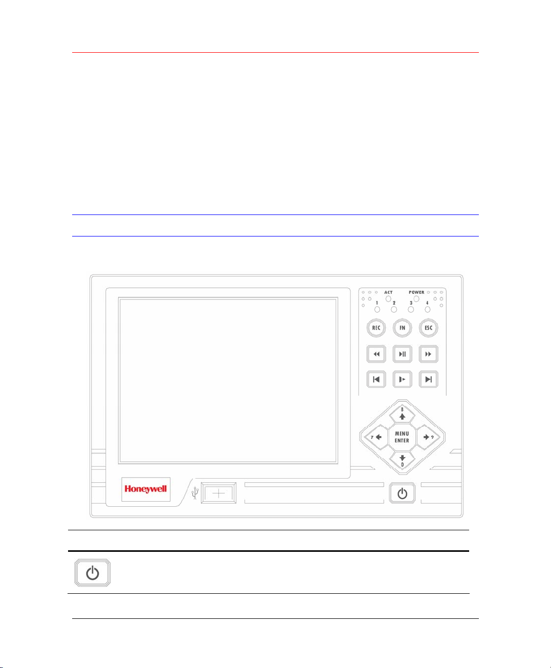
Front Panel
Figure 3-1 Front Panel
Icon Name Function
Power
8
Turn on power.
Page 21
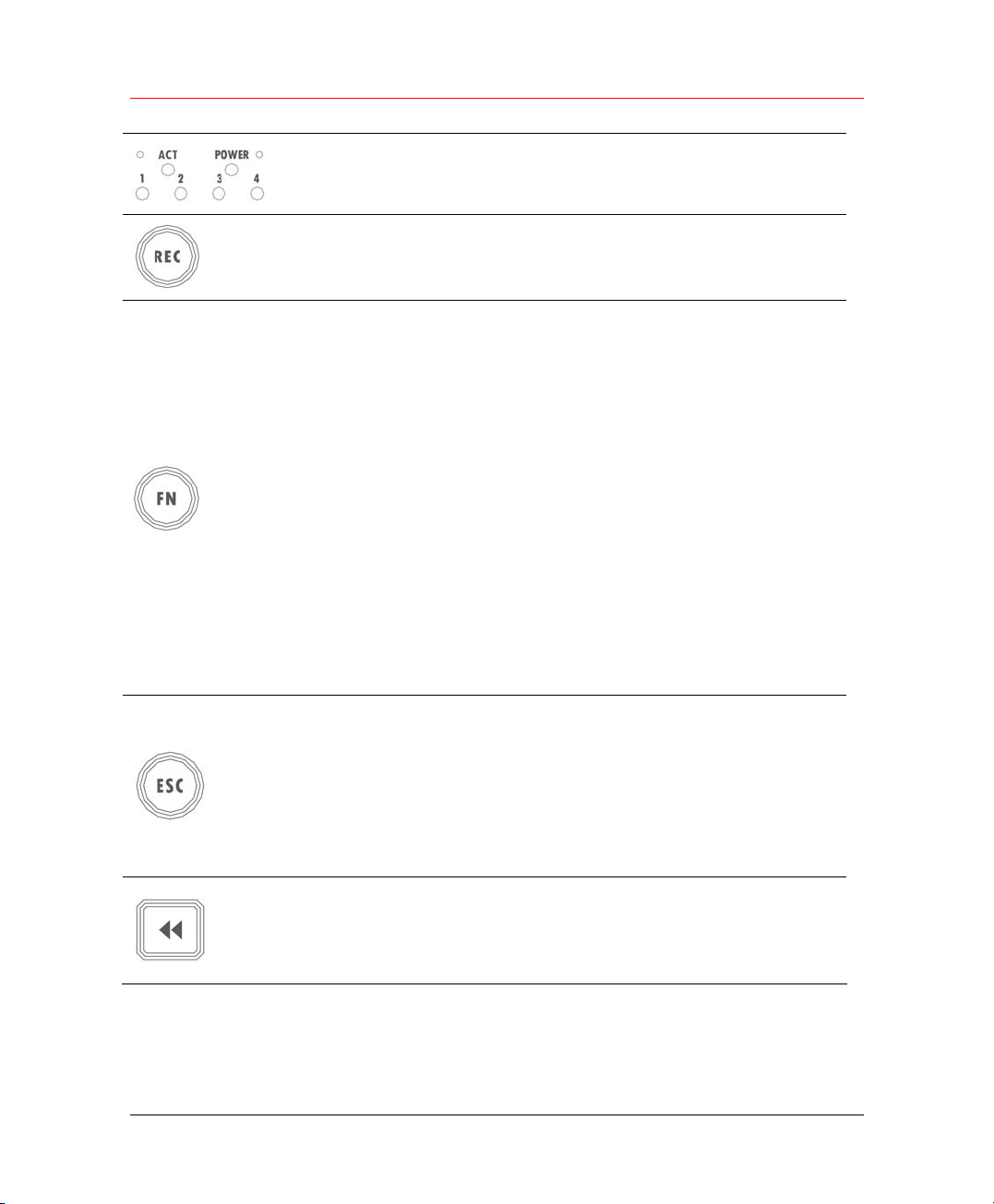
ACT, Power and
channel indicators
(top right)
Honeywell
LED indicators
Record
Assistant
Cancel
Working with direction keys to enable/disable
record
In 1-window display mode, click this button to go
to assistant menu: PTZ control and Video color.
Working with direction keys to realize motion
detection zone setup.
Clear function: Press Fn about 1.5 seconds to
clear all contents in current text box.
In preview mode (There is no other menu
available), press this button for 3 seconds to
switch between TV/VGA.
For HD1 series DVR, there are three modes:
TV/VGA/VGA LCD 60Hz LCD output)
In text input mode, click this button continuously
to switch between numeral/capitalized character
and small character expansible).
Working with other keys to realize special
functions in some menu items.
Cancel
In playback mode, click this button to go back to
real-time monitor mode.
Note:
In numeral input mode,
Click this button to input 0.
Fast backward V
arious fast play and normal playback Speeds.
9
Page 22
Panel Controls
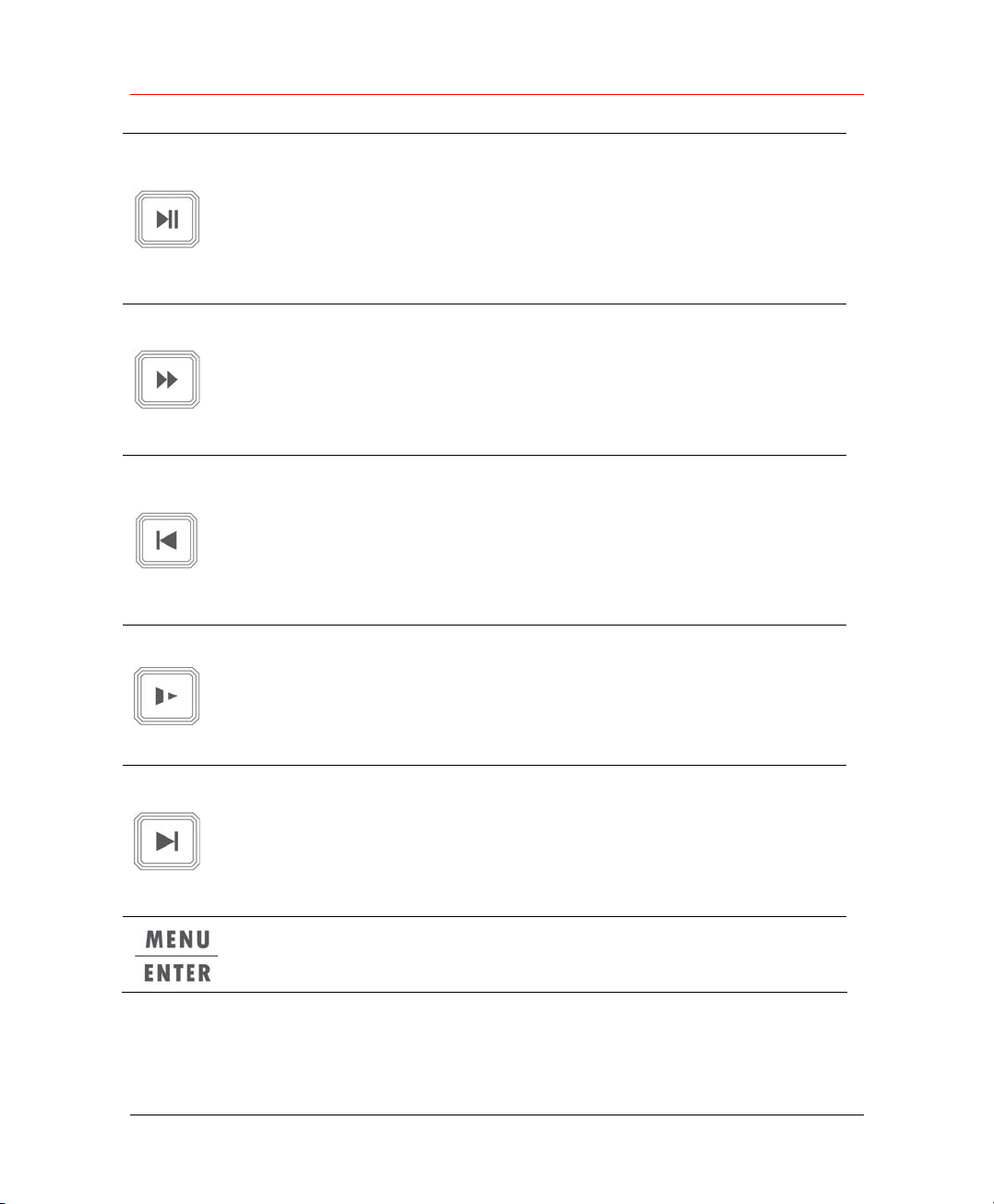
Play/Pause
Fast forward
Play previous
Play/Pause
In real-time monitor mode, click this button to go
to search interface.
Note:
In numeral input mode, click this button to input
3.
Various fast play and normal playback
Speeds.
Note:
In numeral input mode, click this button to input
4.
When playback, click this button to display
previous file.
In menu operation, go to previous menu item.
Note:
In numeral input mode, click this button to input
1.
10
Various slow playback and normal playback.
Speeds.
Slow play
Play next
Menu/Enter
Note:
In numeral input mode, click this button to input
2.
In playback mode, play the next file.
In menu operation, go to the next menu item.
Note:
In numeral input mode, click this button to input
5.
Confirm
Go to the main menu
Page 23

Direction keys
Honeywell
In real-time monitor mode, click left/right direction
keys to switch between one-window and
multiple-windows.
Increase/decrease numeral
Modify setup
Switch PTZ control
Note:
In numeral input mode, Click S to input 6.
In numeral input mode, Click T to input 7.
In 1-window real-time monitor mode, lick
up/down keys to switch monitor channel.
Switch PTZ control
Note:
In numeral input mode, Click W to input 8.
In numeral input mode, Click X to input 8.
Rear Panel
USB
The rear panel is shown as below.
11
Page 24
Panel Controls
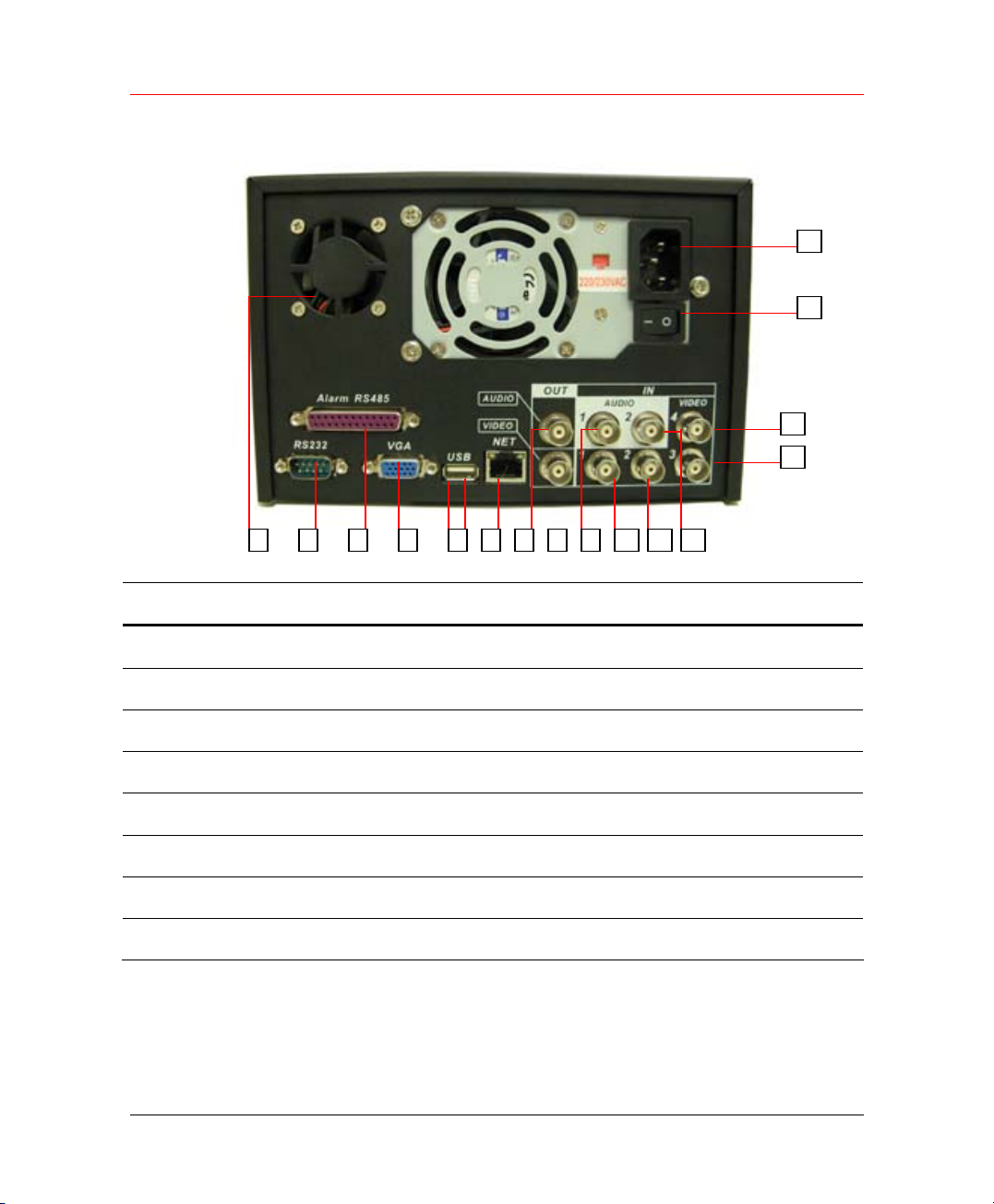
Figure 3-2 Rear Panel
16
15
13
14
2
# Description # Description
1 RS232 9 The first audio input channel
2 Fan 10 The first video input channel
3 VGA 11 The second audio input channel
4 ALARM-RS485 Port 12 The second video input channel
5 USB 13 The forth video input channel
6 Network connection (RJ45) 14 The third video input channel
7 Audio output 15 Power button
8 Video output 16 Power socket
654 3 1
12 111097 8
12
Page 25

4 Installation and Connections
This chapter describes the installation and connection of HLVR4.
Honeywell
Note
All the installation and operations here should conform to
your local electricity safety rules.
Check Unpacked DVR
When you receive the DVR from the shipping agency, please check
whether there is any visible damage to the DVR appearance. The
protective materials used for the package of the DVR can protect most
accidental clashes during transportation. Then you can open the box to
check the accessories.
Please check the items in accordance with the list on the warranty card.
Finally you can remove the protective film of the DVR.
HDD Installation
Calculate HDD Size
This series have no limit to HDD capacity. You can use 120G-750G HDD
to guarantee higher stability.
The formula of total HDD size is:
Total Capacity (MB) = Camera Amount * Recording Hours * HDD Usage
Per Hour (M/h)
When you calculate the total HD capacity, you should estimate the
average HDD capacity per hour for each channel.
For example, for a 4-ch DVR, the average capacity of HDD usage per
hour per channel is 200M/h. Now if you hope the DVR can record the
video 12 hours each day for 30 days, the total capacity of HDDs needed
13
Page 26
Installation and Connections
is: 4 channels * 30 days * 12 hours * 200 M/h = 288G. So you need to
install one 300G HDD or 2 160G HDDs.
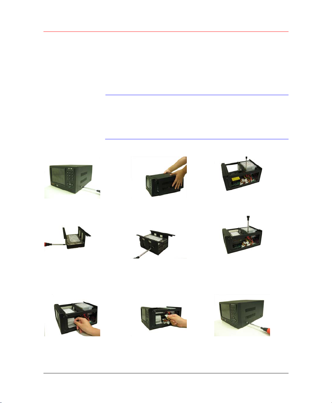
HDD Installation
Data ribbons, fastening screws and smart HDD shelf design are already
provided in the accessories.
Please pay attention to HDD jumper:
If you just need to install one HDD, you can set the HDD to
Note
Please follow the instructions below to install HDD.
MASTER.
If you install two HDDs to one IDE port, you need to set the
farther one as MASTER and the other as SLAVE. Please
don’t set HDD as CS Enable or Cap Limit.
1. Loosen the screws.
4. Install the first HDD. Note the
HDD is placed upside down.
Please make sure bracket is in
correct position.
7. Connect HDD cable to IDE
port。
2. Remove the unit cover.
5. Install the second HDD on
the bracket.
8. Connect power cord to the
HDD.
3. Dismantle the HDD bracket.
6. Fix the HDD bracket into the
internal unit.
9. Place the unit cover back
and screws firmly.
14
Page 27

After HDD installation, please check connection of data ribbon and power
cord.
CD/DVD Burner Installation
Connect USB burners to DVR USB port.
This series DVR is compatible with various burner brands popular in
today’s market. You can consult our local technical support or visit our
website for more information.
Desktop and Rack Mounting
Desktop Mounting
To prevent surface damage, please make sure that the rubber feet are
securely installed on the four corners of the bottom of the unit.
Position the unit to allow for cable and power cord clearance at the rear of
the unit. Be sure that the air flow around the unit is not obstructed.
Honeywell
Rack Mounting
The DVR occupies two rack units of vertical rack space.
The hardware necessary to mount the DVR into a rack is supplied with the
unit.
Install the cabinet in ventilated place. Avoid extreme heat, humid or dusty
conditions. You can use a soft dry brush to clean opening outlet, cooling
fan and etc regularly.
Connecting Power Supply
Please check input voltage and device power button match or not.
We recommend you use UPS to guarantee steady operation, DVR life
span, and other peripheral equipments operation such as cameras.
Connections
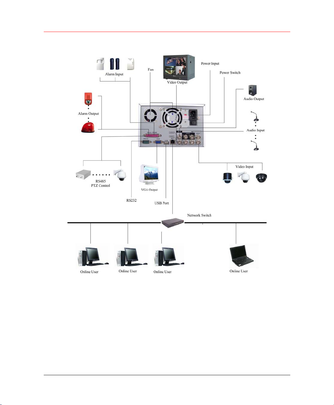
Here is a connection sample for your reference.
15
Page 28
Installation and Connections
Figure 4-1 Connection Sample
Connecting Video Input and Output Devices
Connecting Video Input
The DVR automatically detects the video standard (PAL or NTSC)
whenever you connect a video input. It accepts color, black-and-white and
analog video.
16
Page 29

Honeywell
• Enabling line lock on cameras may cause video
distortion. There may be noise in the camera’s power
source. If video from one or more cameras is distorted,
Note
To connect each video input:
1. Connect a coaxial cable to the camera or other analog video source.
2. Connect the coaxial cable to the video in connector on the rear panel.
Please refer to
we recommend you disable line lock on the camera as
your first troubleshooting step.
• If a video distribution amplifier is installed between the
video source and the DVR, do not set the output video
level above 1 Vp-p.
Figure 4-1 for more information.
Note
You need to use a BNC installation tool to connect coaxial
cables to the rear panel.
Connecting Video Output
This section provides information about physically connecting video
display devices to the DVR.
If you connect the DVR with a TV monitor or VGA monitor, the DVR can
automatically detects the monitor type. And without any output device, by
default, the DVR is configured to use a TV monitor. In this case, if your
application requires a VGA monitor, you have to press the button “Fn” or
Shift on the front panel to switch.
Video output 1 and VGA can’t display at the same time. But
Note
Video output 2 can display properly with Video Output 1 or
VGA.
Connecting Audio Input and Audio Output
HLVR4 has 2-ch audio input, 1-ch audio output, 4-ch alarm input and 3-ch
alarm output.
Audio Input/Audio Output
The DVR encodes audio and video signals simultaneously, which lets you
control audio at the monitored location.
To set up audio:
17
Page 30

Installation and Connections
1. Make sure your audio input device matches the RCA input level. If the
device and RCA input levels do not match, audio distortion problems may
occur.
2. Make sure the audio connector is wired as in
3. Connect a line input device or pre-amplified microphone to the audio
connector for the video channel on the rear panel.
Alarm Input and Relay Output
The DVR offers 4-ch alarm input for external signaling devices, such as
door contacts or motion detectors. Each alarm input can be either
normally open or normally closed. Once configured, an alarm input can
invoke many different activities, including triggering a relay device,
sending an alert to a security office or storing pre-alarm video to the DVR.
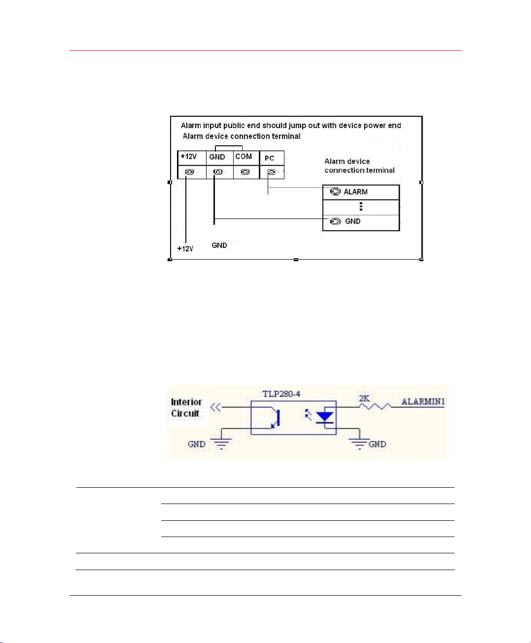
Connecting Alarm Input and Alarm Output
Alarm Input
You should check your alarm input mode is grounding alarm input or not.
For this series DVR, grounding signal is needed for alarm input.
If you need to connect two units or one DVR and other device, please use
relay to separate them.
Figure 4-1.
18
Alarm Output
Do not connect alarm output port directly with high power load (no more
than 1 A) in case of heavy current.
You can use the co-contactor to realize the connection between the alarm
output port and the load.
Alarm Input and Output Details
You can refer to the following sheet and figures for alarm input and output
information.
Page 31
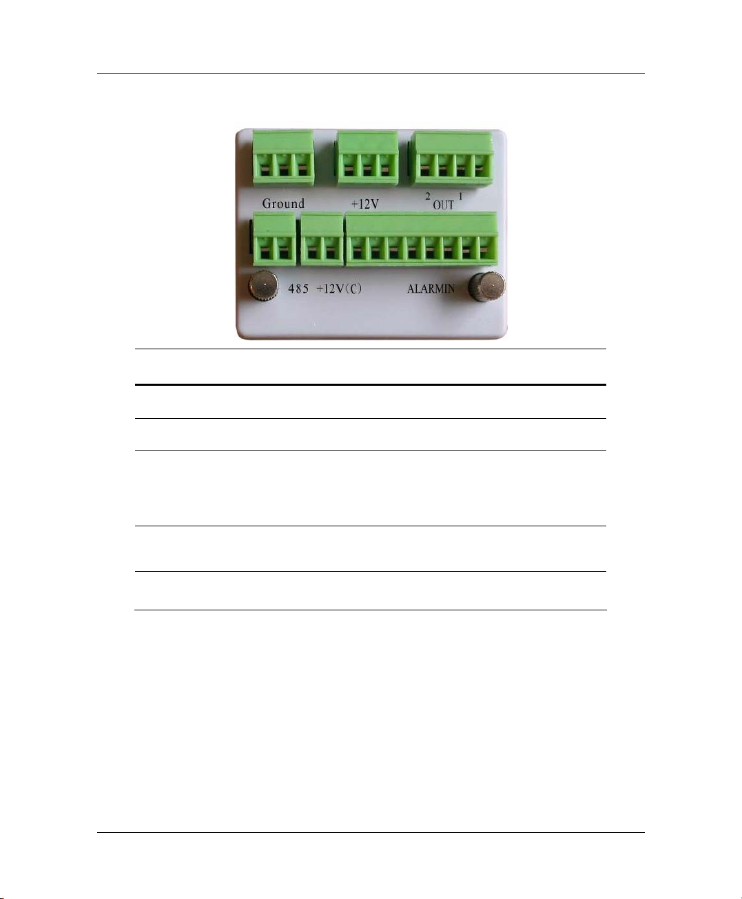
Figure 4-2 Alarm Input/Output
Parameter Grounding Alarm
Ground Ground line
Alarm in 1…4 1, 2, …, 4. Become activated in low voltage,
Honeywell
Relay Output
485 A、B
+12(C)
1,2,3,4: NO and C(Normally Open and Com)
5: NO,C and NC(Normally Open, Com, Normally Closed)
6: Ctrl 12V(This is used for reset the senor)
485 communication port. They are used to control devices such
as PTZ.
This should input an external power input(Less than 1 A).
• 4-ch grounding alarm inputs(Normal open or Normal close type).
• Please parallel connect COM end and GND end of the alarm
detector (Provide external power to the alarm detector).
• Please parallel connect the Ground of the DVR and the ground of
the alarm detector.
• Please connect the NC port of the alarm sensor to the DVR alarm
input (ALARM).
• If you need to reset the touched-off alarm remotely, you can use
DVR to supply controllable 12 V power to the alarm detector such as
the smoke detector.
19
Page 32
Installation and Connections
• Use the same ground with that of DVR if you use external power to
the alarm device.
Figure 4-3 Connection
Relay Output Description
• 3 ways relay alarm output. Provide external power to external alarm
device.
• To avoid over loading, please read the following relay parameters
sheet carefully (See below table).
• The controllable +12v can be used to restore the smoke detector.
Figure 4-4 Relay Output
Rating(resistance
load)
Temperature
20
Relay Specification
Rated switch capacity 30VDC 2A, 125VAC 1A
Maximum switch power 125VA 160W
Maximum switch voltage 250VAC, 220VDC
Maximum switch currency 1A
-40℃ ~+70℃
Page 33

RS232
RS485
Honeywell
You can connect the DVR with POS or Keyboard through RS232.
With POS system, the DVR can communicate through RS232 and
network. For the POS system, the DVR can integrate the text content and
even search the record through the info.
When the DVR receives a camera control command, it transmits that
command up the coaxial cable to the PTZ device. RS485 is a singledirection protocol; the PTZ device can’t return any data to the unit. To
enable the operation, connect the PTZ device to the RS485(A, B) input on
the DVR. Since RS485 is disabled by default for each camera, you must
enable the PTZ settings first. This series DVRs support multiple protocols
such as Pelco-D, Pelco-P.
To connect PTZ devices to the DVR:
1. Connect RS485 A,B on the DVR rear panel.
2. Connect the other end of the cable to the proper pins in the connector
on the camera.
3. Follow the instructions for configuring a camera to enable each PTZ
device on the DVR.
Other Interfaces
There are still other interfaces on the DVR, such as USB ports.
21
Page 34

Overview of Navigation and Controls
5 Overview of Navigation and Controls
Before operation, please make sure you have properly installed HDDs and
all the cable connections.
Login, Logout and Main Menu
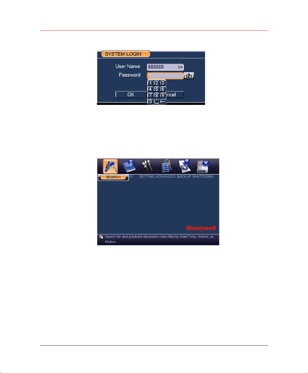
Login
When the system boots up, default video display is in multiple-window
mode.
Click Enter or left click mouse, you can see the login interface.
The system consists of four accounts:
• Username: admin. Password: admin. (administrator, local and
network)
• Username: 888888. Password: 888888. (administrator, local only)
• Username: 666666. Passwords: 666666(Lower authority user who
can only monitor, playback, backup and etc.)
• Username: default. Password: default(hidden user)
For your system security, please modify you password after first login.
You can use USB mouse, front panel or keyboard to input. About input
method: Click
(small/capitalized) and denotation.
to switch between numeral, English character
22
Note
3 times login failure in 30 minutes will result in account lock!
Page 35
Main Menu
Honeywell
Figure 5-1 Login
When you login, the system main menu is shown as below.
There are total six icons: search, information, setting, advanced, backup
and shutdown. Click the icon to enter the sub-menu.
Figure 5-2 Main Menu
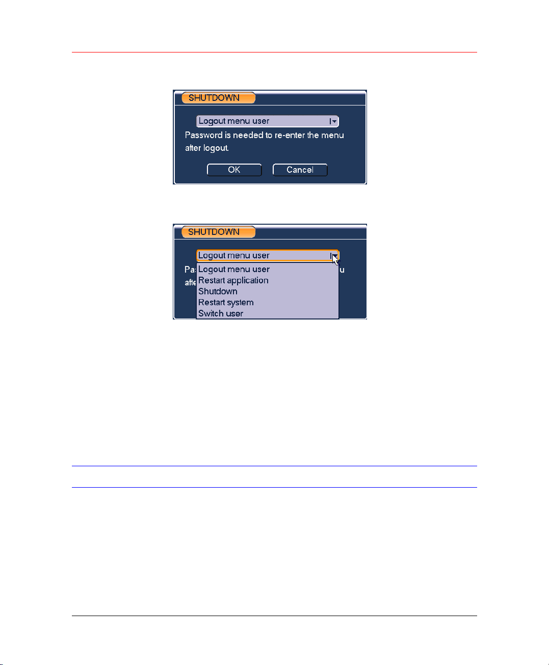
Logout
There are two ways for you to log out.
• Press the power button on the front panel for at least 3 seconds,
system will stop all operations. Then you can click the power button
in the rear panel to turn off the DVR.
• In the main menu, click shutdown button, you can see an interface is
shown as below.
23
Page 36
Overview of Navigation and Controls
Figure 5-3 Logout
Select one option in the drop-down list and click OK.
Figure 5-4 Shutdown Options
Auto Recovery after Power Failure
The system can automatically backup video and recovery previous
working status after power failure.
Replace Battery
Please make sure to use the same battery capacity and model if possible.
We strongly recommend replacing battery regularly (such as one-year) to
guarantee system time accuracy.
Recording Operation
Live Viewing
When you login, the system is in live viewing mode. You can see system
date, time and channel name. If you want to change system date and time,
you can refer to general settings (Main Menu Æ Setting Æ General). If
you want to change the channel name, please refer to the display settings
(Main Menu Æ Setting Æ Display).
24
Page 37
Status icon displays in each video window.
Honeywell
Note
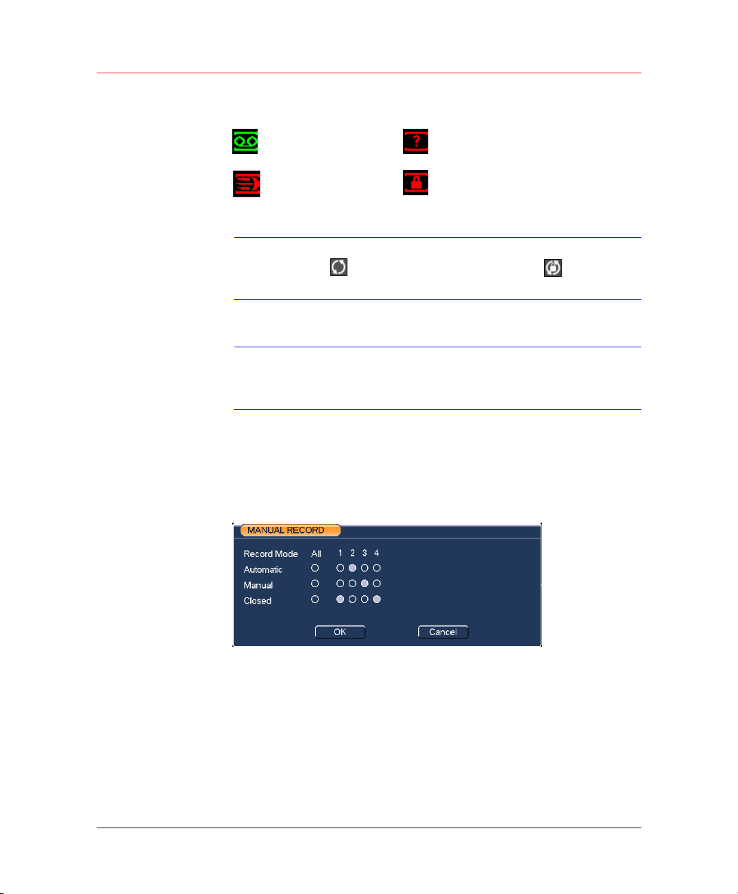
Manual Recording
Note
To go to the Manual Record menu,
• Right click mouse or in the main menu, Advanced Æ Manual
• In live viewing mode, click record button in the front panel.
Figure 5-5 Manual Record
Recording
Motion detection
Please refer to the following sheet for channel status. The
icon
closing switch function.
You need to have proper rights to implement the following
operations. Please make sure the HDDs have been properly
installed.
Record.
Video loss
Camera lock
stands for opening switch function, stands for
Record Mode:
• Manual – the highest priority. After manual setup, all selected
channels will begin ordinary recording.
• Automatic – channel records as you have set in recording setup
(Main Menu->Setting->Schedule).
• Closed – all channels stop recording.
25
Page 38

Overview of Navigation and Controls
Highlight icon“○” to select corresponding channel. System is in
automatic mode by default.
Enable/Disable recording
Please check current channel status: “○” means it is not in recording
status, “●” means it is in recording status.
You can use mouse or direction key to highlight channel number.
Enable Recording of All Channel
Highlight “○” below All, you can enable all channel recording.
• All channel automatic record
Please highlight “ALL” after “Automatic”. When system is in automatic
recording, all channels will records as you have previously set (Main
menu Æ Setting Æ Schedule).
The corresponding indication light in front panel will turn on.
• All channel manual record
Please highlight “ALL” after “Manual.” When system is in manual
recording, all scheduled set up you have set will be null ((Main menu
Æ Setting Æ Schedule).
The corresponding indication light in front panel will turn on.
Close all channel recording
Please highlight “ALL” after “Closed”. System closes all channels
recording no matter what mode you have set in the menu (Main menu Æ
Setting Æ Schedule).
Search & Playback
Click Search in the main menu and the interface is shown as below.
26
Page 39
Honeywell
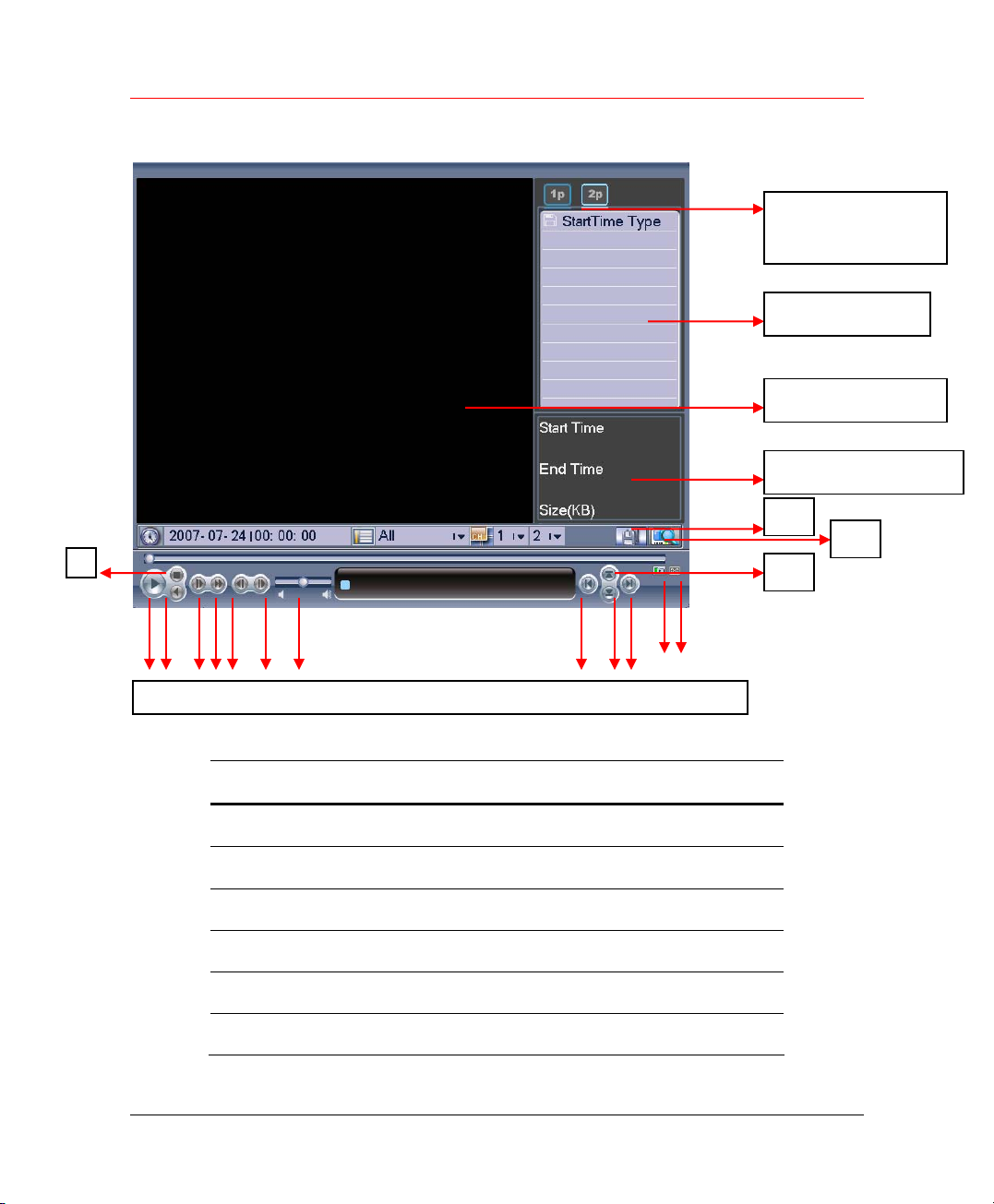
Figure 5-6 Search
1-window Playback
2-window Playback
File List
Playback Window
File Information
14
13
3
1 2 4 5 6 7 8 9 10 11 15 16
# Description # Description
12
1 Play 9 Previous file
2 Backward 10 Next channel
3 Stop 11 Next file
4 Slow play 12 Previous channel
5 Fast play 13 Search
6 Previous frame 14 Backup
27
Page 40

Overview of Navigation and Controls
7 Next frame 15 Circularly play
8 Volume 16 Full screen
Usually there are three file types:
• R: regular recording file.
• A: external alarm recording file.
• M: motion detection recording file
• C: card and POS test overlay recording file For some special series
only)
There are several playback windows. System supports 1/2-ch playback.
Playback
There are various search modes: video type, channel number or time. The
system can max display 32 files in one screen. You can use up/down
button to scroll pages.
Select the file name and double click mouse (or click enter button), you
can view file content.
28
Accurate playback
Input time (h/m/s) in the time column and then click playback button,
system can operate accurate playback.
Synchronized playback function when playback
During playback process, click numeral key, system can switch to the
corresponding channel video of the same time.
Digital zoom
When the system is in full-screen playback mode, drag your mouse in the
screen to select a section and then left click mouse to realize digital zoom.
You can right click mouse to exit.
File backup
System supports backup operation during search. You can draw a √
before file name (multiple choices). Then click backup button (Button 14 in
Figure 5-6)
Slow playback and fast playback
Please refer to the following sheet for slow play and fast playback function.
Page 41

Honeywell
Button Description
In playback mode, click this button to switch between various
Fast play
Slow play
Play/Pause
Previous/next
Backward playback
In normal playback mode, left click backward play button “_”, system
begins backward playback.
Click backward play button again, system goes to pause mode.
When system is in backward play or frame by frame playback mode,
you can click play button to go to normal playback.
Frame by Frame Playback
fast play modes such as fast play 1,fast play 2 and more.(4
speed levels)
Frame rate may vary due to different versions.
In playback mode, click this button to switch between various
slow play modes such as slow play 1 or slow play 2.(4 speed
levels)
In slow playback mode, click it to switch between play/pause
modes.
In playback mode, you can click _ and ` to view previous or
next video in current channel.
All the operations here (such as playback speed, channel,
Note
time and progress) have relationship with hardware version.
Some series DVRs do not support some functions or
playback speeds.
Calendar
When it is in Pause mode, click the next frame to play one frame forward.
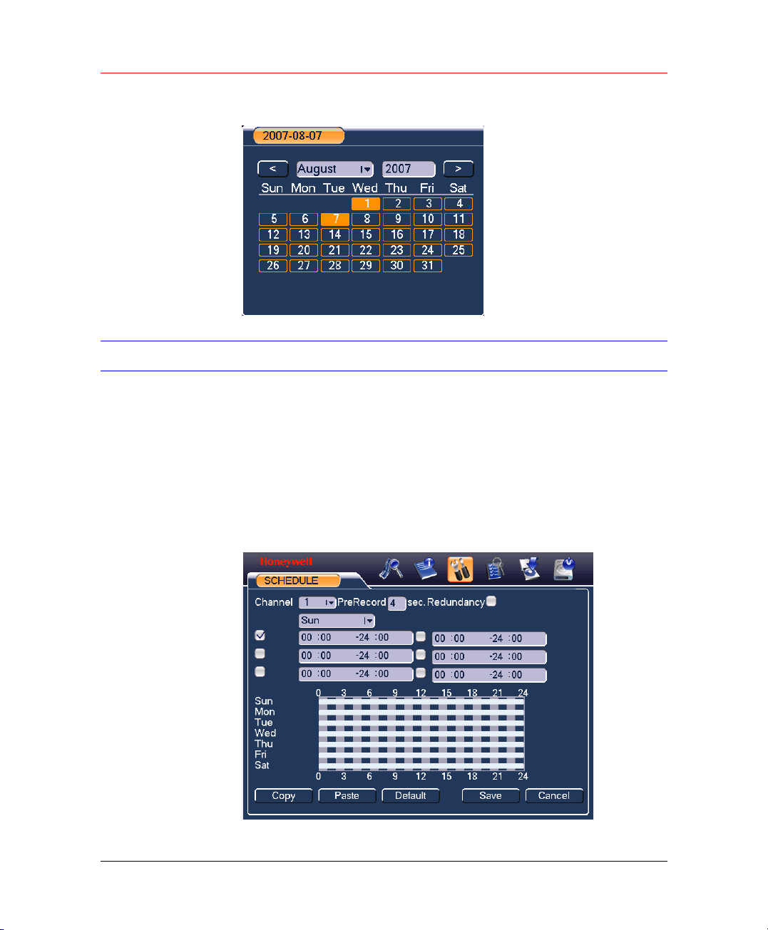
Click calendar icon in Figure 5-6, system pops up calendar for your
reference.
Highlighted date means that there are record files in that day. You can
click yellow date to view file list.
In the following figure, there are video files in August 1st and 7th. Click
date to view file list.
29
Page 42
Overview of Navigation and Controls
Figure 5-7 Calendar
Record Setup (Schedule)
When the system boots up, it is in default 24-hour regular mode. You can
set record type and time in schedule interface.
Schedule Menu
30
In the main menu, from setting to schedule, you can go to schedule menu.
There are three record types: R-Regular, MD-Motion detection, A- Alarm.
In some series, system also supports C-Card.
Figure 5-8 SCHEDULE
Page 43

Basic Operation
In the above figure, there are the following settings:
• Channel: Please select the channel number first. You can select “all”
• Week day: There are eight options: ranges from Saturday to
• Redundancy: System supports redundancy backup function. You
• Prerecord: System supports prerecord function. The previous 1 to
• Time period: Set within which time period the recording performed.
• Record types: There are three types: regular, motion detection (MD)
Enable functions or set time periods by checking the boxes before them.
After completing all configurations, click Save and it returns to the
previous menu.
Honeywell
if you want to set for the whole channels.
Sunday and All.
can highlight Redundancy button to activate this function. Please
note, before enabling this function, set at least one HDD as
redundant. Refer to the manual for detailed information.
16 seconds video before alarm occurs can be included in recorded
video.
and Alarm.
Quick Settings
This function allows you to copy one channel setup to another. After
setting in Channel 1, you can click Copy and turn to Channel 2 and then
click Paste button. You can finish setting for one channel and then click
Save or you can finish all setup and then click Save to memorize all the
settings.
Redundancy
Redundancy function allows you to memorize record file in several disks.
These files are created, packaged and closed simultaneously. When
there is file damage occurred in one disk, there is a spare one in the other
disk. You can use this function to maintain data reliability and safety.
In the main menu, from Setting to Schedule, you can highlight redundancy
button to enable this function. See
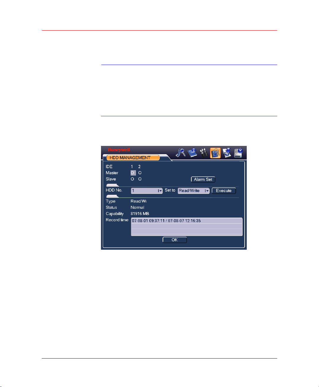
In the main menu, go to ADVANCED Æ HDD MANAGEMENT, you can
set one or more disk(s) as redundant. You can select from the dropdown
list. See
disk is full.
Figure 5-9. System automatically overwrites old files once hard
Figure 5-8.
31
Page 44
Overview of Navigation and Controls
Please note that only read/write disk or read-only disk can backup file and
support file search function, so you need to set at least one read-write disk
otherwise you can not record video.
About redundancy setup please note:
• If current channel is not recording, current setup
gets activated when the channel begins recording
Note
When completing all settings, click Save and it returns to the previous
menu.
Figure 5-9 HDD MANAGEMENT
the next time.
• If current channel is recording now, current setup
will get activated right away, the current file will be
packet and form a file, then system begins
recording as you have just set.
32
Playback or search in the redundant disk.
There are two ways for you to playback or search in the redundant disk.
• Set redundant disk(s) as read-only disk or read-write disk (Main
menu Æ ADVANCED Æ HDD MANAGEMENT). System needs to
reboot to get setup activated. Now you can search or playback file in
redundant disk.
• Dismantle the disk and play it in another PC.
Page 45
Detect
Honeywell
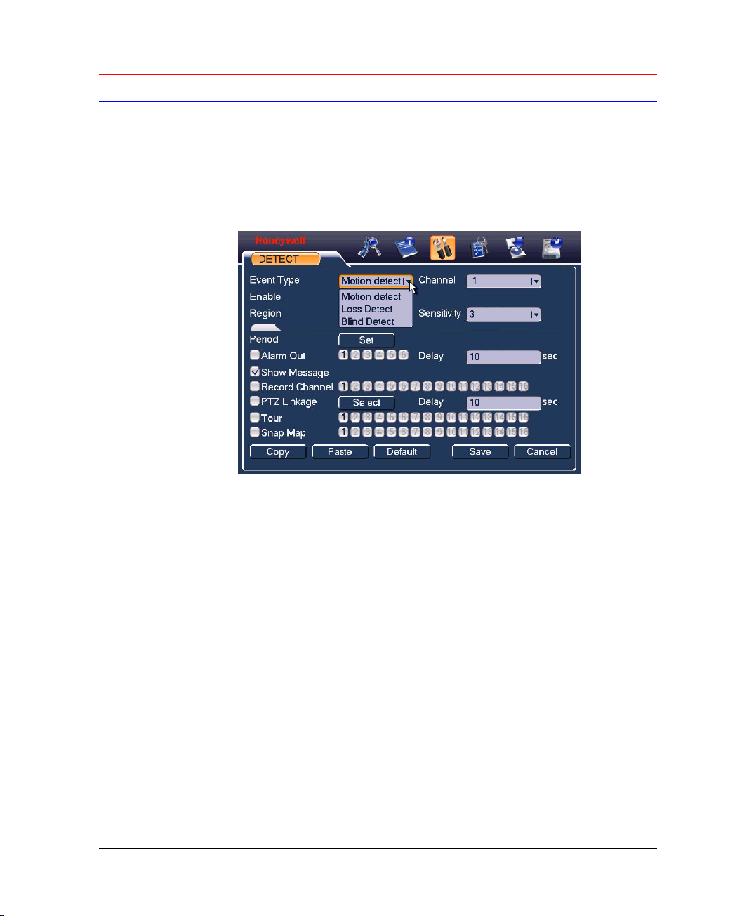
In the main menu, go to SETTING Æ DETECT, you can see motion detect
interface. There are three event types: Motion detect, Loss detect and
Blind detect.
Figure 5-10 DETECT
Motion Detect
In Event Type, it selects Motion detect by default.
33
Page 46

Overview of Navigation and Controls
Figure 5-11 Motion Detection
• Channel: select the channel you want to implement motion detection.
• Record Channel: select the channel to activate recording function
once alarm occurred. Please make sure you have set MD record in
encode interface (Main Menu->Setting->Schedule) and schedule
record in manual record interface (Main Menu->Advanced->Manual
Record).
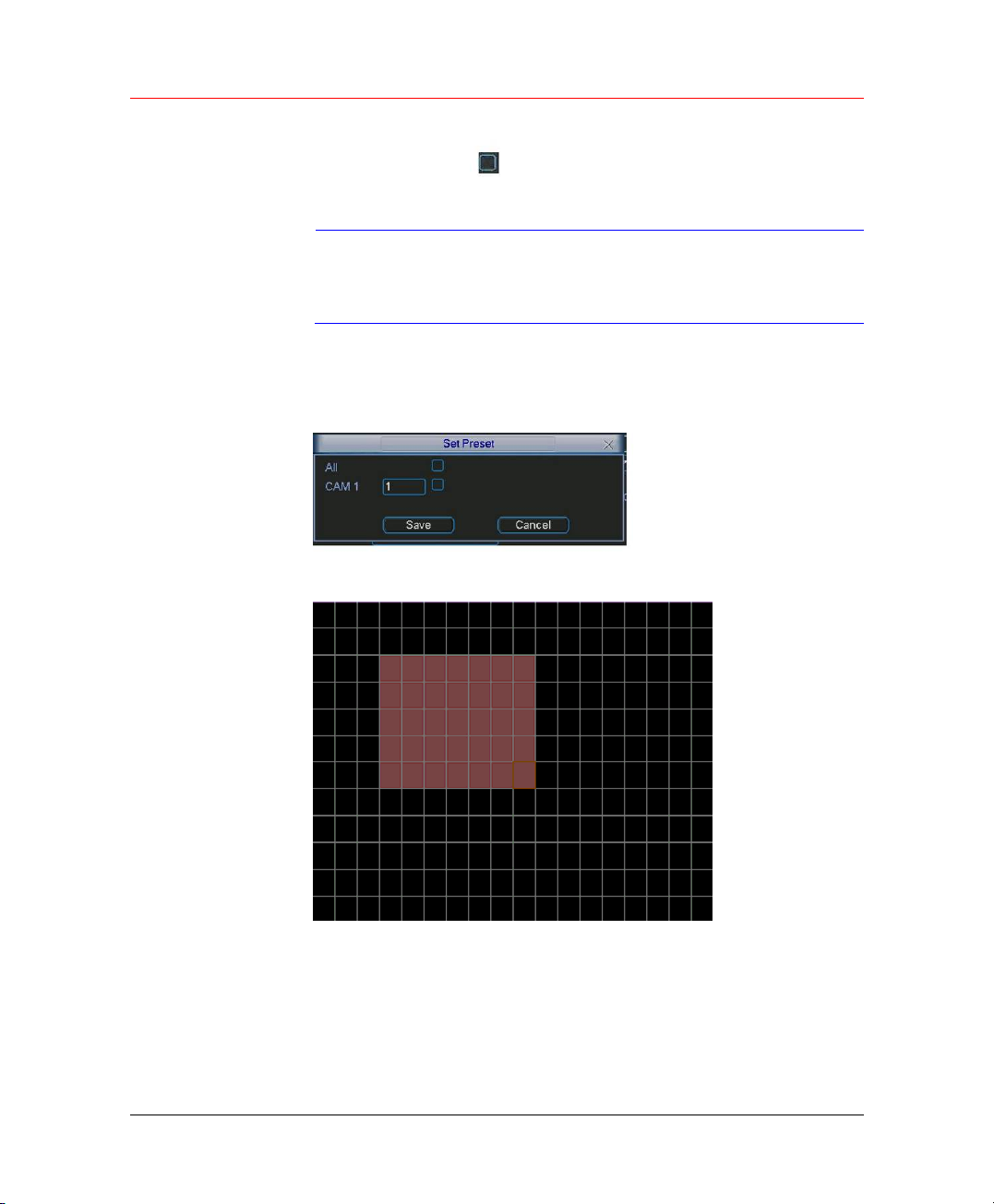
• Tour: Here is for you to activate tour between different cameras.
• Delay: when motion detection complete, system auto delays
detecting for a specified time. The value ranges from 10-300(Unit:
second).
• PTZ Linkage: Click set button, the interface is shown as in
5-12.Here you can set PTZ Linkage for one or more channels.
• Region: click “select” button to set motion detection region. See
above figure.
• Sensitivity: there are six levels. The sixth-level is of the highest
sensitivity.
• Alarm Out: when alarm occurred, system enables peripheral alarm
devices.
• Show Message: System pops up message in the screen to alert you
once alarm occurred.
Figure
34
Page 47
Honeywell
Please highlight icon to select the corresponding function. When
completing all configurations, click Save, it goes back to the previous
menu.
In motion detection mode, you can not use copy/paste to set
Note
In Figure 5-11, you can left click mouse and then drag it to set a region for
motion detection. Click Fn to switch between deployment and withdraw for
motion detection. After setting, click enter button to exit.
Figure 5-12 Preset
Figure 5-13 Motion Detection Region
channel setup since the video in each channel may not be
the same.
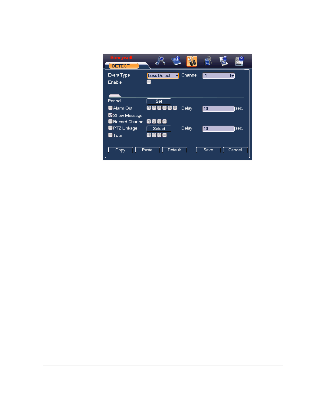
Loss Detect
In Event Type, select Loss Detect from the drop-down list.
35
Page 48
Overview of Navigation and Controls
Figure 5-14 Loss Detect
Loss detect allows you to be informed when video loss phenomenon
occurred. You can enable alarm output channel and then enable show
message function.
• Channel: select the channel you want to enable lens shading alarm.
• Enable: Enable or disable loss detect.
• Period: Set the active period.
• Alarm Out: activate peripheral alarm device when video loss
occurred.
• Delay: when motion detection completes, system auto delays
detecting for a specified time. The value ranges from 10-300(Unit:
second).
• Show Message: System pops up message in the screen to alert you
once alarm occurred. Please highlight icon to enable this function.
• Record Channel: select the channel to record when video loss
occurred.
• PTZ Linkage: Click Select to set PTZ Linkage for one or all channels.
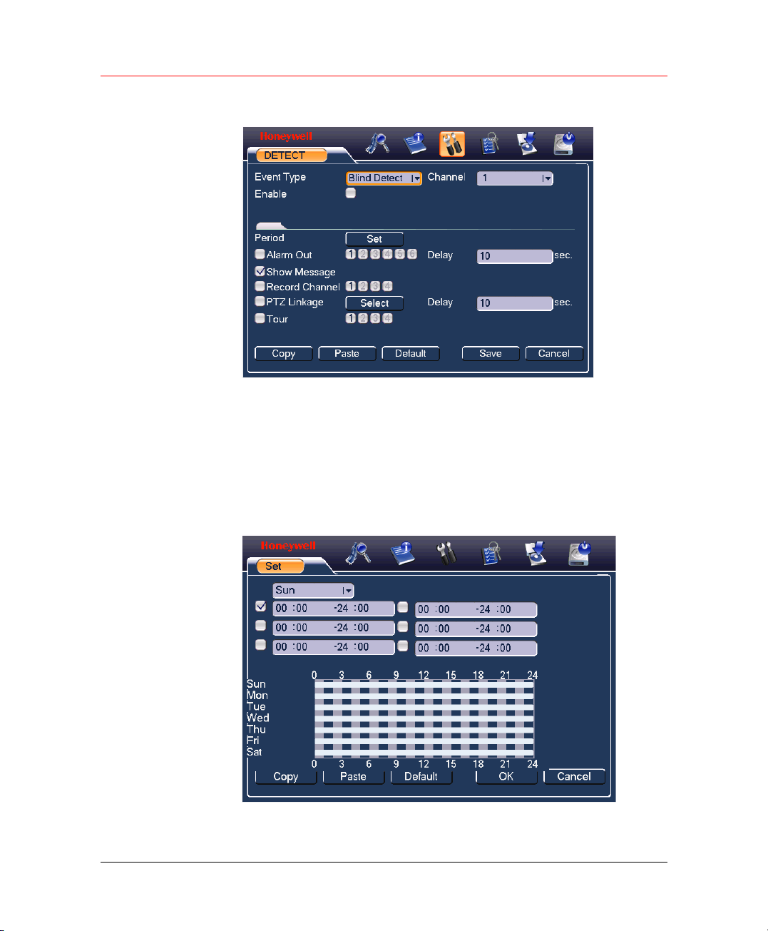
Blind Detect
36
• Tour: Here is for you to activate tour between different cameras.
In Event Type, select Blind Detect from the drop-down list.
Page 49
Honeywell
Figure 5-15 Blind Detect
When someone viciously masks lens, the system can alert you to
guarantee video continuity.
• Channel: select the channel you want to enable camera mask
detection function.
• Enable: Enable or disable blind detect.
• Period: Set the active period. Click Set to open the following window:
Figure 5-16 Set Period
37
Page 50
Overview of Navigation and Controls
• Alarm Out: activate peripheral alarm device when camera mask
occurred.
• Delay: when motion detection completes, system auto delays
detecting for a specified time. The value ranges from 10-300(Unit:
second).
• Show Message: System pops up message in the screen to alert you
once alarm occurred. Please highlight icon to enable this function.
• Record Channel: select the channel to record when camera mask
occurred.
• PTZ Linkage: Click set button to set PTZ Linkage for one or all
channels.
• Tour: Here is for you to activate tour between different cameras.
In this interface, copy/paste function is only valid for the
Note
same type, which means you can not copy a channel setup
in loss detect mode to blind detect mode.
Alarm Setup and Alarm Activation
38
Before operation, please make sure you have properly connected alarm
devices such as buzzer.
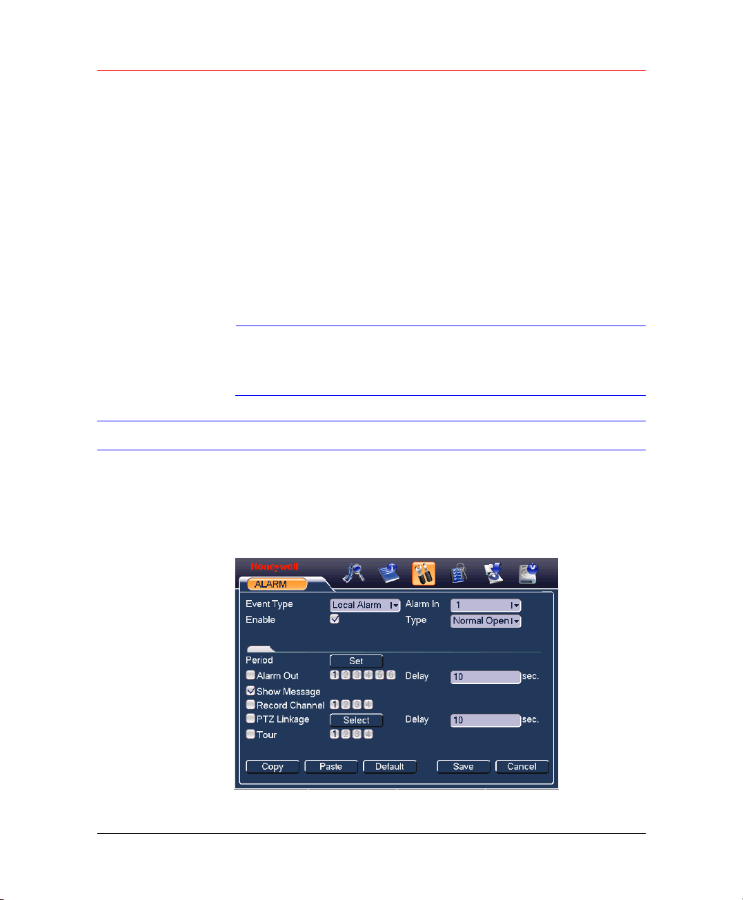
In the main menu, select SETTING Æ ALARM.
Figure 5-17 ALARM
Page 51

Honeywell
Alarm In: here is for you to set channel number.
• Event Type: Local Alarm and Net Alarm.
• Alarm In: Select the alarm-in channel (4 channels).
• Enable: Enable or disable alarm function.
• Type: Normal Open and Normal Close.
• Period: Set the active period.
• Alarm Out: select proper alarm activation output channel (multiple
choices).
• Delay: Here is for you to set proper delay duration. Value ranges
from 10 to 300 seconds. System automatically delays specified
seconds in turning off alarm and activated output after external alarm
cancelled.
• Show Message: System pops up message in the screen to alert you
once alarm occurred.
• Record Channel: you can select proper channel to record alarm
video (Multiple choices). At the same time you need to set alarm
record in schedule interface (Main Menu->Setting->Schedule) and
select schedule record in manual record interface (Main Menu>Advance->Manual Record).
• PTZ Linkage: Here is for you to activate PTZ control.
• Tour: Here is for you to activate tour between different cameras.
Backup
Please highlight icon
completing all the setups, click Save and it goes back to the previous
menu.
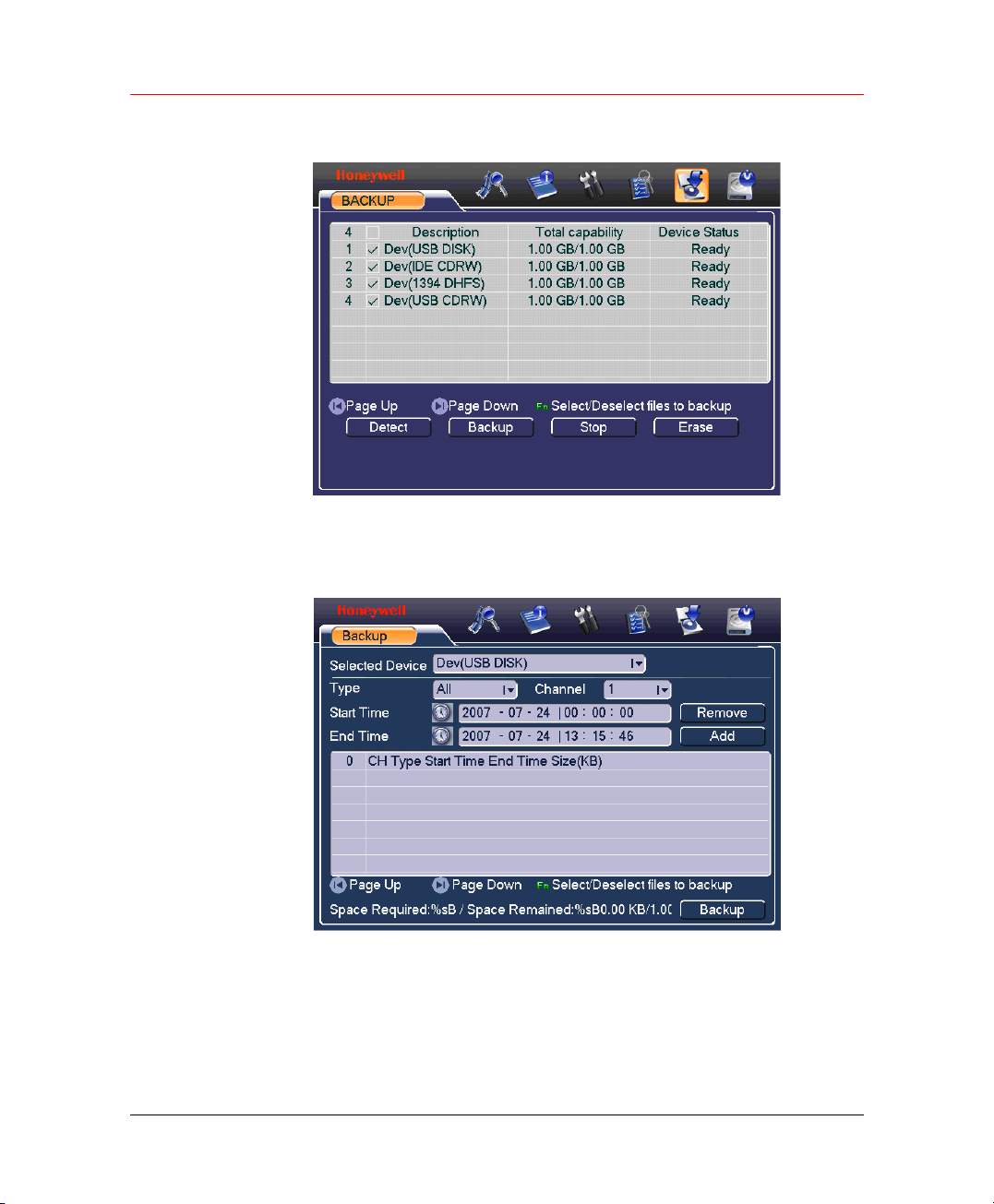
In the main menu, select Backup and the following interface is displayed.
to select the corresponding function. When
39
Page 52
Overview of Navigation and Controls
Figure 5-18 BACKUP
It lists the information of devices.
Check one device and click Backup.
Figure 5-19 Backup Device
40
Click Add, system begins search. All matched files are listed below.
System automatically calculates the capacity needed and remained. See
system only backups files with a “√” before channel name. You can use
Fn or Cancel button to delete “√” after file serial number.
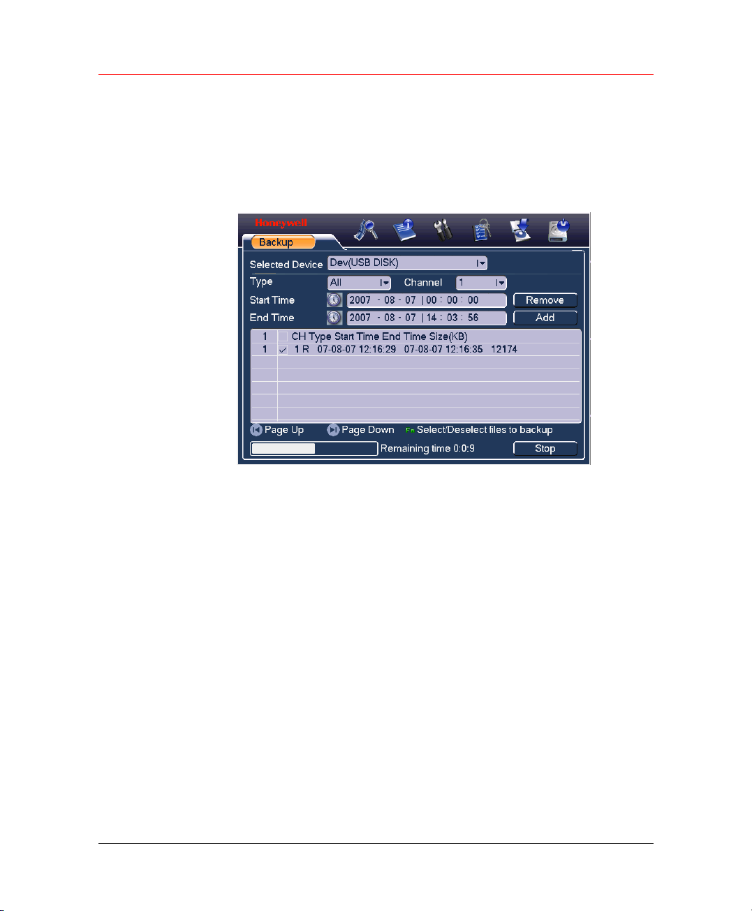
Click Backup, you can backup selected files. There is a process bar for
you reference.
Page 53
Honeywell
When the system completes backup, you can see a dialogue box
prompting successful backup.
Click Backup, system begins burning. At the same time, the backup
button becomes stop button. You can view the remaining time and
process bar at the left bottom.
Figure 5-20 Backup in Process
Tips:
During backup process, you can click ESC to exit current interface; but the
system will not terminate backup process.
Note:
When you click Stop button during the burning process, there are two
conditions for different devices:
• For CD/DVD burner device, the stop function becomes activated
immediately and there is no data in the burner.
• For USB device, system can backup the data before you click Stop
button. For example, if there is a file of 10 minutes, when you click
stop after five minutes backup, system only save the previous 5minute data in the device.
The file name format usually is: SN_CH+channel number+time
Y+M+D+H+M+S. In the file name, the YDM format is the same as you set
in general interface. (Main Menu ->Setting ->General).You can visit our
website to view listed CD-ROM types.
41
Page 54
Overview of Navigation and Controls
PTZ Control and Color Setup
All the operation here is based on PELCOP protocol.
Cable Connection
Please follow the procedures below to go on with cable connection:
• Connect the dome RS485 port to DVR 485 port.
• Connect dome video output cable to DVR video input port.
• Connect power adapter to the dome.
PTZ Setup
The camera video should be in the current screen. Before setup, please
check the following connections are right:
• PTZ and decoder connection is right. Decoder address setup is right.
• Decoder A (B) line connects with DVR A (B) line.
Boot up the DVR, input user name and password.
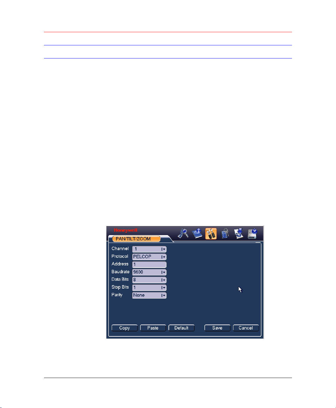
In the main menu, click SETTING ÆPAN/TILT/ZOOM.
Figure 5-21 PAN/TILT/ZOOM
42
• Channel: select the current camera channel.
• Protocol: select corresponding PTZ protocol (such as PELCOP).
Page 55
Honeywell
• Address: default address is 1.
• Baud rate: select corresponding baud rate. Default value is 9600.
• Data Bits: select corresponding data bits. Default value is 8.
• Stop Bits: select corresponding stop bits. Default value is 1.
• Parity: there are five options: none/odd/even/mark/space. Default
setup is none.
After completing all the settings, click Save.
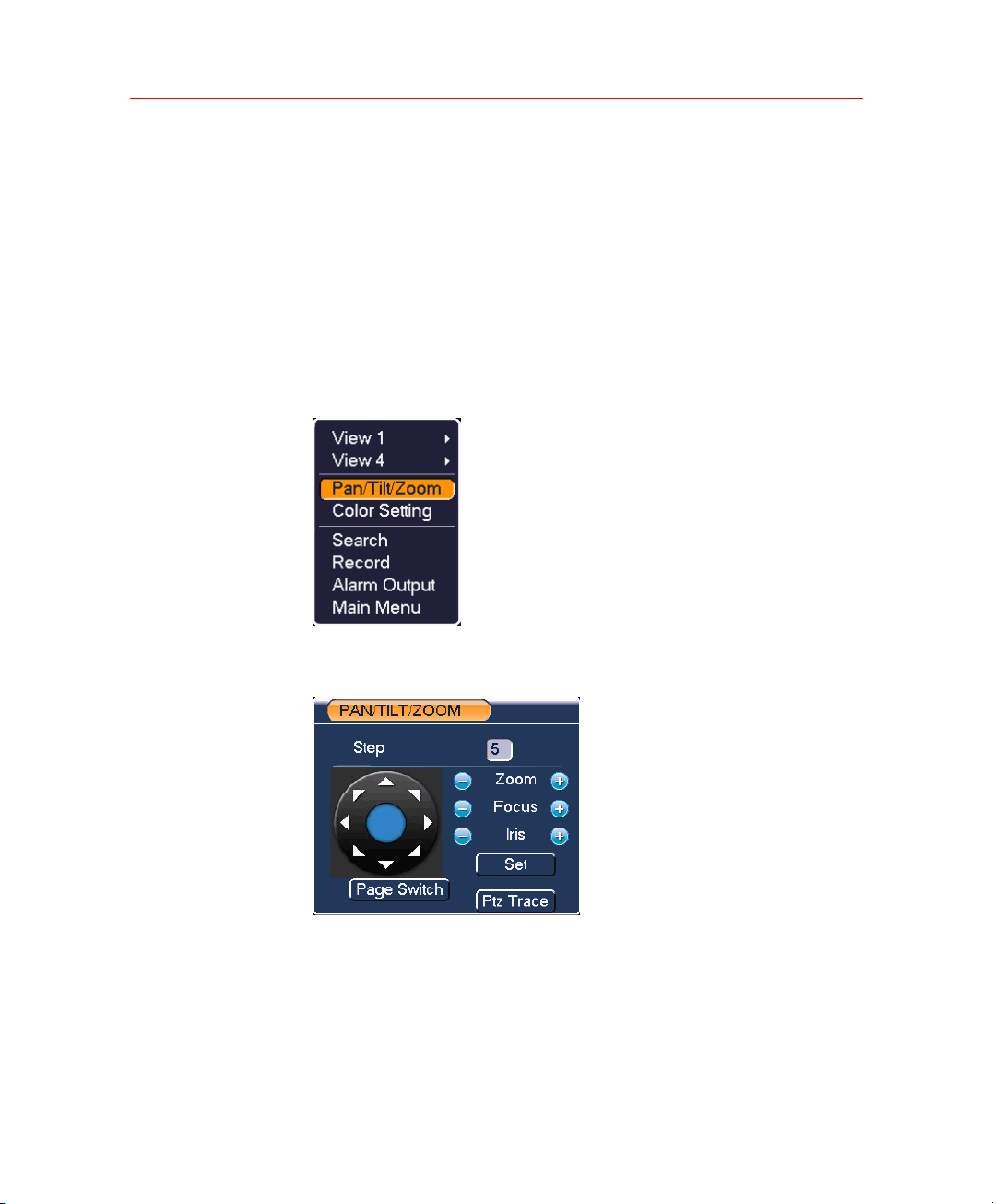
In one window display mode, right click mouse (click “Fn” Button in the
front panel). The interface is shown as in
Figure 5-22 Right Click Menu
Figure 5-21.
Click Pan/Tilt/Zoom, the interface is shown as below.
Figure 5-23 PAN/TILT/ZOOM Adjust
Here you can set the following items:
• Step: value ranges from 1 to 9.
• Zoom
• Focus
• Iris
43
Page 56
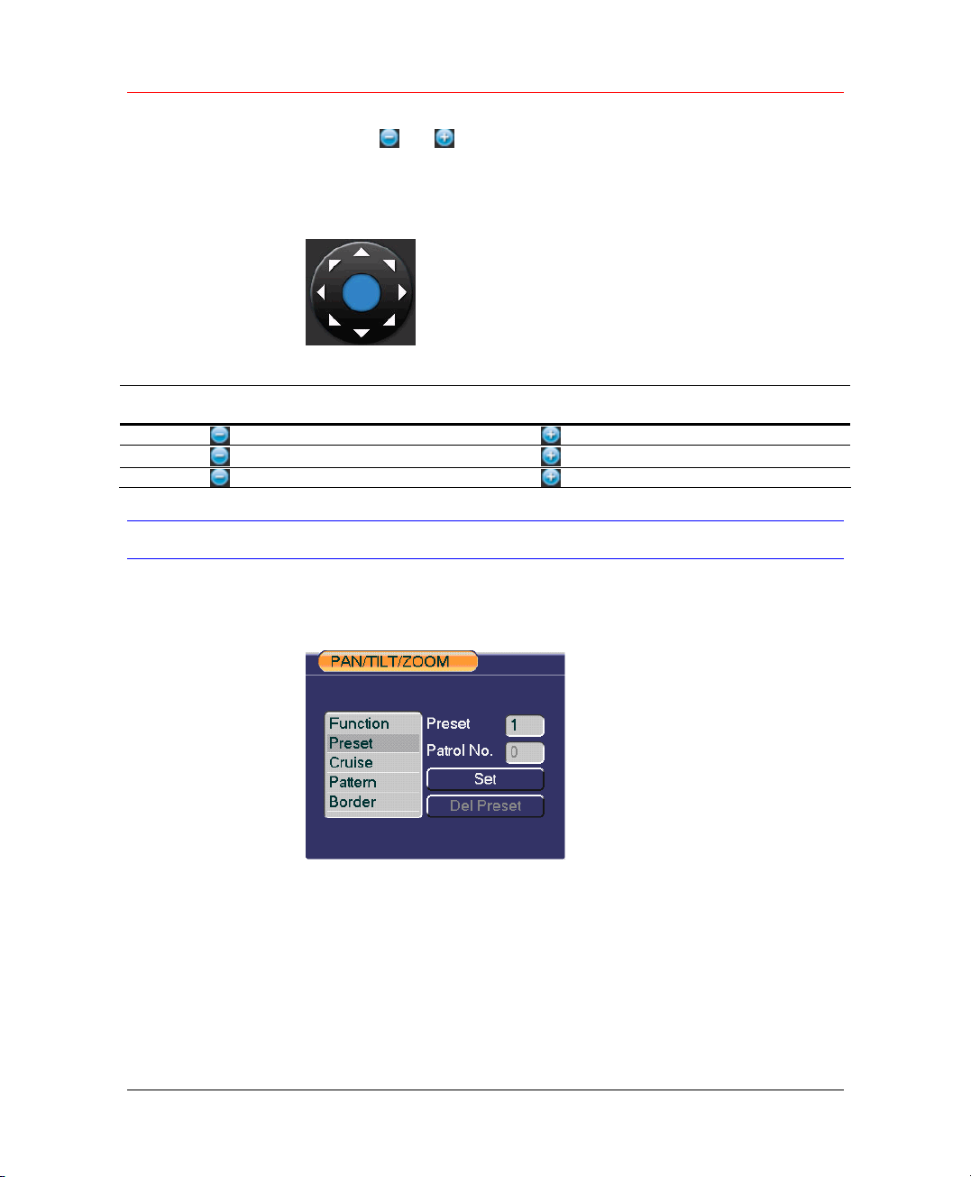
Overview of Navigation and Controls
Click icon and to adjust zoom, focus and iris.
To adjust PTZ position, click the direction arrows. There are totally 8
direction arrows.
Figure 5-24 Direction Arrows
Here is a sheet for you reference.
Name
Zoom
Focus
Iris
Function
key
function
Near ►
Near
Close W
Shortcut
key
_
Preset/Patrol/Pattern/Scan
In Figure 5-23, click the Set:
Figure 5-25 PAN/TILT/ZOOM – Set
Function
key
function
Far
Far
Open f
Shortcut
Key
►
44
Here you can set the following items:
• Preset
• Cruise
• Pattern
• Border
Figure 5-23, click Page Switch:
In
Page 57
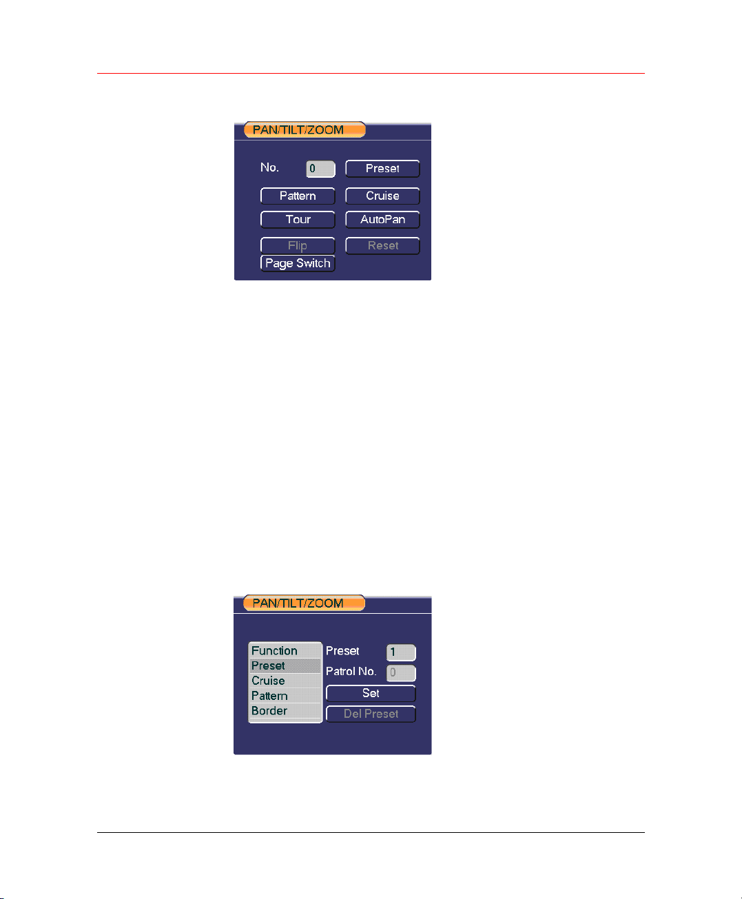
Figure 5-26 PAN/TILT/ZOOM – Page Switch
Here you can activate the following functions:
• Preset
• Cruise
• Pattern
• Tour
• Auto pan
• Flip
• Reset
Honeywell
Preset Setup
In Figure 5-23, use eight direction arrows to adjust camera to the proper
position.
In Figure 5-26, click Preset and input preset number.
Figure 5-27 PAN/TILT/ZOOM – Preset
Now you can add this preset to one cruise.
45
Page 58
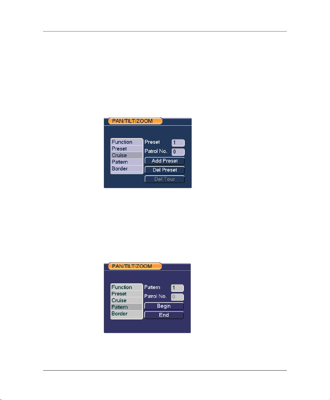
Overview of Navigation and Controls
Activate Preset
In Figure 5-26, input preset number in the No. blank, and click Preset
button.
Patrol Setup (Tour setup)
In Figure 5-25, click Cruise button. Input preset number and add this
preset to a cruise. For each cruise, you can input max 80 presets.
Figure 5-28 PAN/TILT/ZOOM – Cruise
Activate Patrol (tour)
Pattern Setup
46
In Figure 5-25, input cruise number in the No. blank and click Cruise
button.
In Figure 5-25, click Pattern and then click Begin.
Figure 5-29 PAN/TILT/ZOOM – Pattern
Then you can go to Figure 5-23 to modify zoom, focus, and iris.
Page 59

Go back to Figure 5-29 and click End button. You can memorize all these
operations as pattern 1.
Activate Pattern Function
In Figure 5-26, input mode value in the No. blank, and click Pattern.
Auto Scan Setup
In Figure 5-25, click Border.
Figure 5-30 PAN/TILT/ZOOM
Go to
Figure 5-23, use direction arrows to select camera left limit.
Then please go to the above figure, click left limit button.
Repeat the above procedures to set right limit.
Honeywell
47
Page 60

Understanding of Menu Operations and Controls
6 Understanding of Menu Operations and
Controls
When you login, the main menu shows as below. There are totally six
icons: SEARCH, INFO, SETTING, ADVANCED, BACKUP and
SHUTDOWN. Move the cursor to highlight the icon, and then click the
menu item to enter the sub-menu.
Figure 6-1 Main Menu
48
This series DVR menu tree is shown as below.
Page 61

Honeywell
Main Menu
SEARCH
INFO
SETTING
HDD INFO
BPS
LOG
VERSION
ONLINE USERS
GENERAL
ENCODE
SCHEDULE
RS232
NETWORK
ALARM
DETECT
ADVANCED
PAN/TILT/ZOOM
DISPLAY
DEFAULT
HDD MANAGEMENT
ALARM OUTPUT
ALARM INPUT
MANUAL RECORD
ACCOUNT
49
Page 62
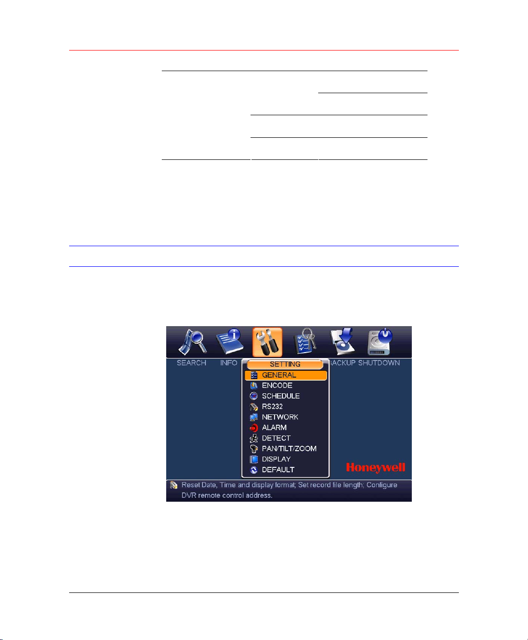
Understanding of Menu Operations and Controls
AUTO MAINTAIN
TV ADJUST
Setting
BACKUP
SHUTDOWN
Please note, you need to click Save at the bottom of the interface to save
the setup you have just made.
You need to highlight check box to enable corresponding function.
Otherwise, this function is disabled.
All the operations below are based on our 4-ch series DVR.
In main menu, highlight setting icon and system setting interface is shown
as below.
Figure 6-2 SETTING
General
50
General setting includes the following items.
Page 63
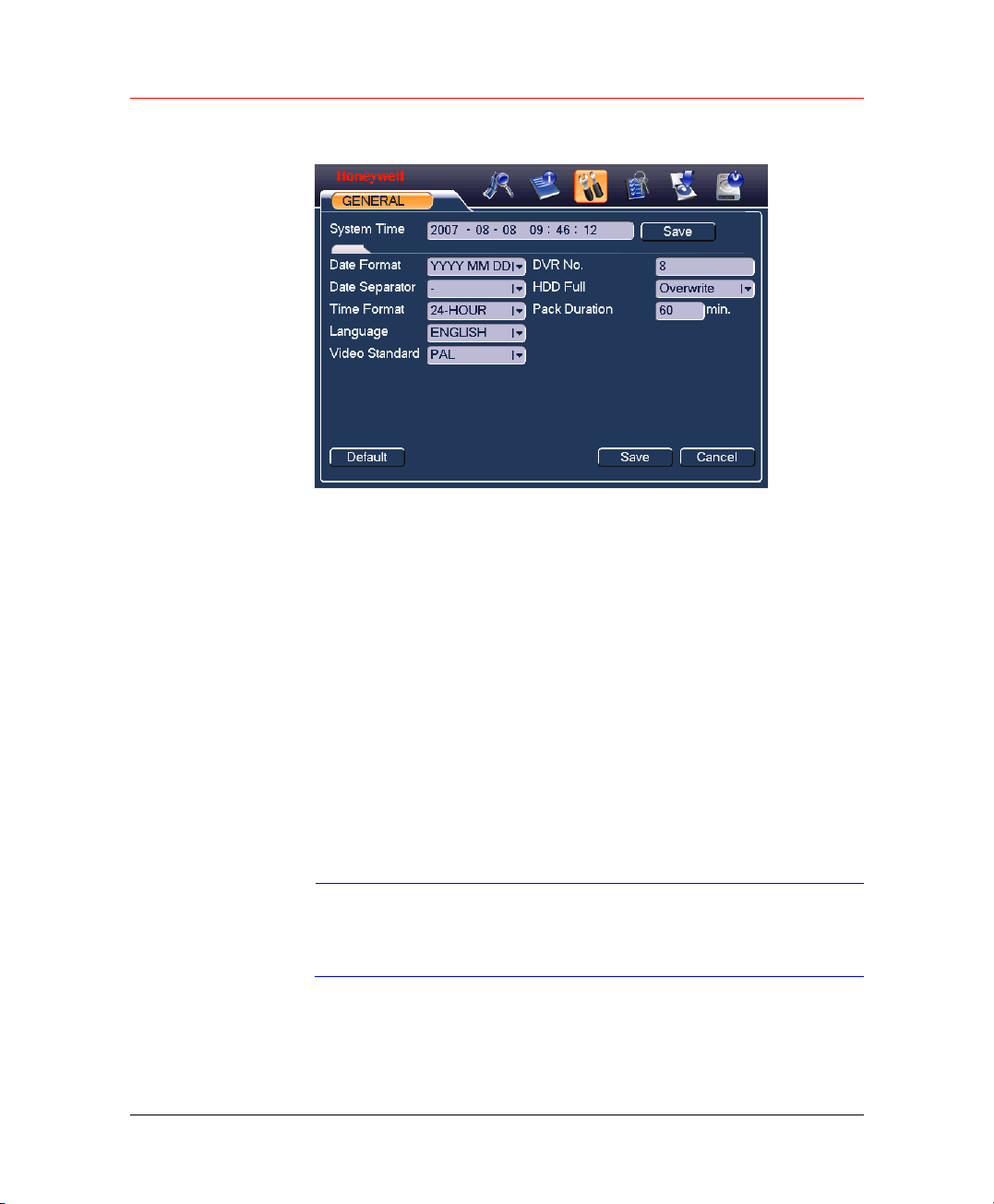
Honeywell
Figure 6-3 GENERAL
• System Time: here is for you to set system time
• Date Format: there are three types: YYYYY-MM-DD: MM-DD-
YYYYY or DD-MM-YYYY.
• Date Separator: there are three denotations to separate date: dot,
beeline and solidus.
• Time Format: there are two types: 24-hour mode or 12-hour mode.
• Language: system supports various languages: Chinese (simplified),
Chinese (Traditional), English, Italian, Japanese, French, Spanish
(All languages listed here are optional. Slight difference maybe found
in various series).
• HDD Full: Here is for you to select working mode when hard disk is
full. There are two options: stop recording or rewrite.
• Pack Duration: Here is for you to specify record duration. Default
value is 60 minutes.
• Video Standard: There are two formats: NTSC and PAL.
Note
After all the setups please click Save button, system goes back to the
previous menu.
Since system time is very important, do not modify time
casually unless there is a must.
51
Page 64
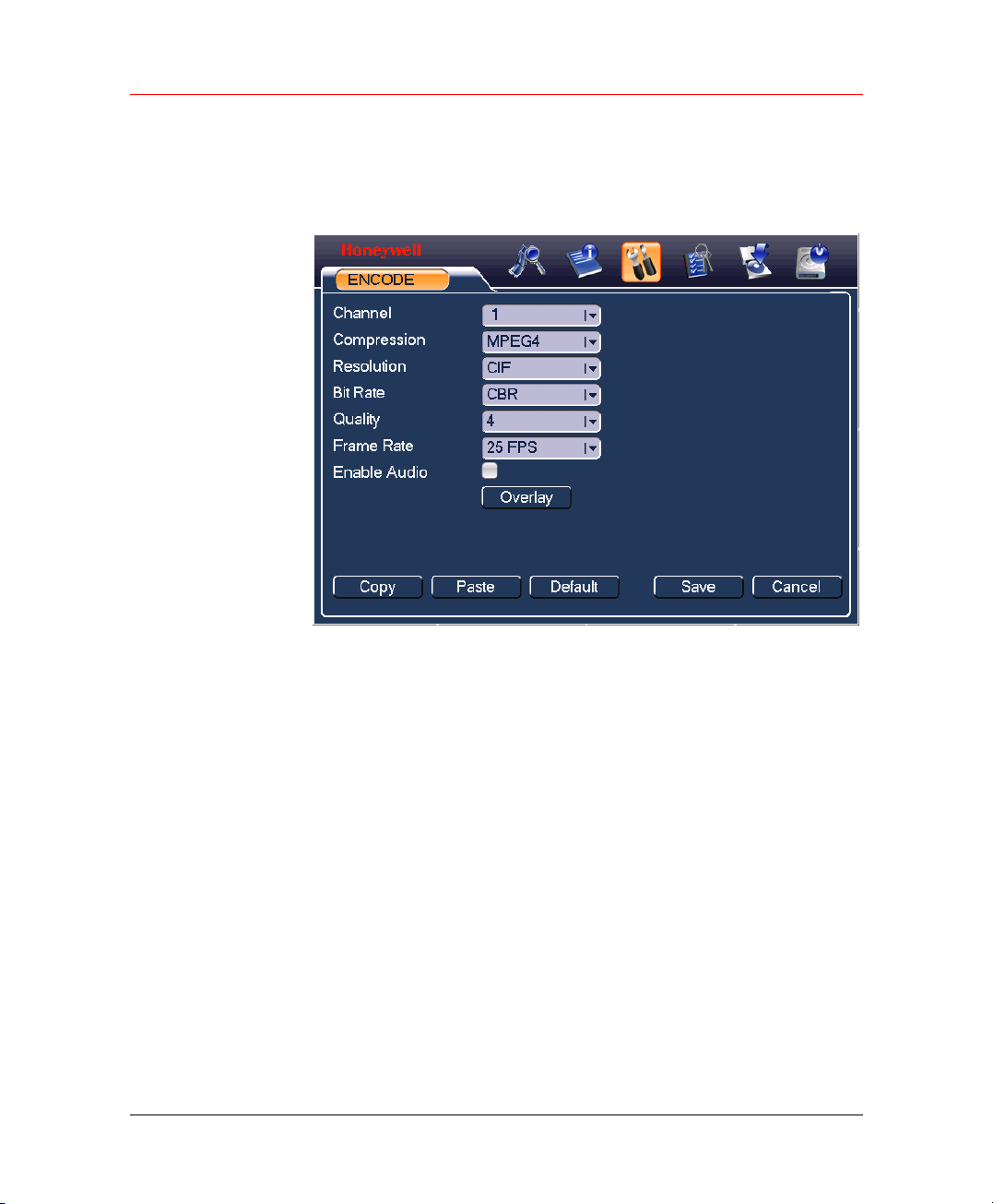
Understanding of Menu Operations and Controls
Encode
Encode setting includes the following items.
Figure 6-4 ENCODE
52
• Channel: Select the channel you want.
• Compression: system supports MPEG4.Or you can select from the
dropdown list.
• Resolution: System supports various resolutions, you can select from
the dropdown list.
• Bit Rate: system supports two types: CBR and VBR.
• Quality: There are six levels ranging from 1 to 6. Level six is the
highest image quality.
• Frame Rate: there are six levels: 1 f/s, 2f/s, 3f/s, 6f/s, 12f/s,25f/s
(Some series DVRs only support PAL 25f/s ).
• Enable Audio/Video: you can turn on or off the audio.
• Overlay: click this button to set time and channel information overlay
location. Click Overlay to open the following window:
Page 65
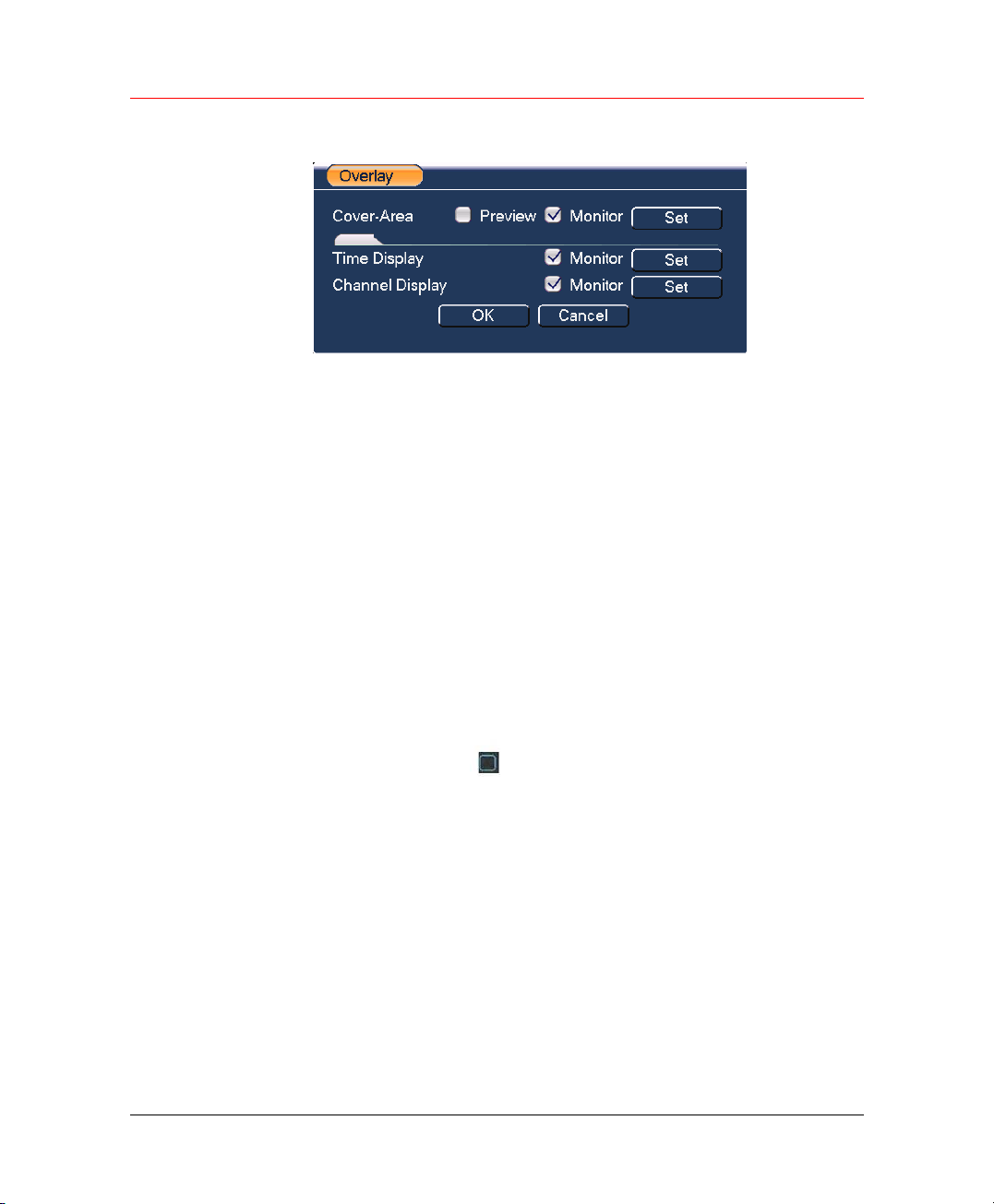
Honeywell
Figure 6-5 Overlay
• Cover area (Privacy mask): Here is for you to set window blanking
section. You can drag you mouse to set proper section size.
• Time display: You can select system displays time or not when
playback.
• Channel display: You can select system displays channel number or
not when playback.
System default setup is:
• Channel:1
• Compression: MPEG4
• Resolution: CIF/D1
• Bit rate: CBR
• Quality: 4
• Frame rate: 25f/s
Schedule
RS232
Please highlight icon to select the corresponding function.
This series DVR is suitable for ATM use. System can overlay card number,
transaction time and etc on the monitor or playback window (Need
protocol support). System also supports search by transaction information
and card number.
Please refer to Record Setup (Schedule) on page 30.
RS232 interface is shown as below. Here are five items.
53
Page 66
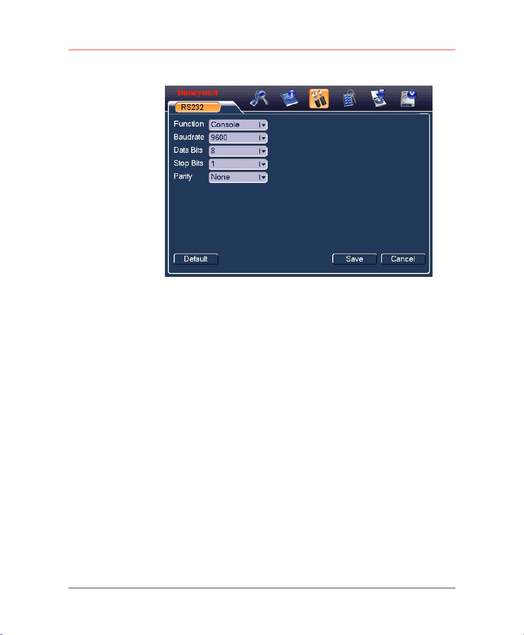
Understanding of Menu Operations and Controls
Figure 6-6 RS232
• Function: There are various devices for you to select.
• Baud rate: You can select proper baud rate.
• Data Bits: You can select proper data bit.
• Stop Bits: There are two values: 1, 2.
• Parity: there are five choices: none/odd/even/mark/space.
After all the setups please click Save, system goes back to the previous
menu.
Network
54
Here is for you to input network information.
Page 67
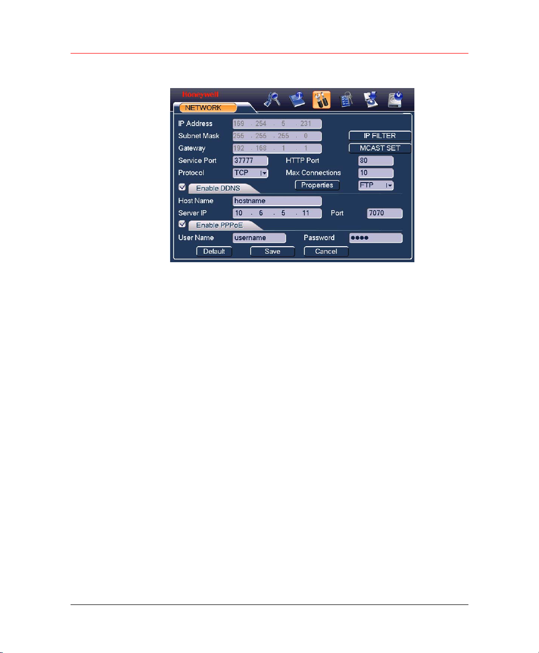
Honeywell
Figure 6-7 NETWORK
• IP Address
• Subnet Mask
• Gateway
• Service Port: Default value is 37777. (System server port 37778 is
reserved for network UDP use.)
• HTTP Port: Default value is 80
• Protocol: You can select proper protocol from the dropdown list.
• Max Connections: support maximal 10 users.
• Properties: There are two options for you: NTP/Alarm center. You
can select corresponding ways and then click Properties button to go
to setup interface.
• IP Filter: When you enable this function, only IP in the list can login
this DVR. Click it to open the following window:
55
Page 68
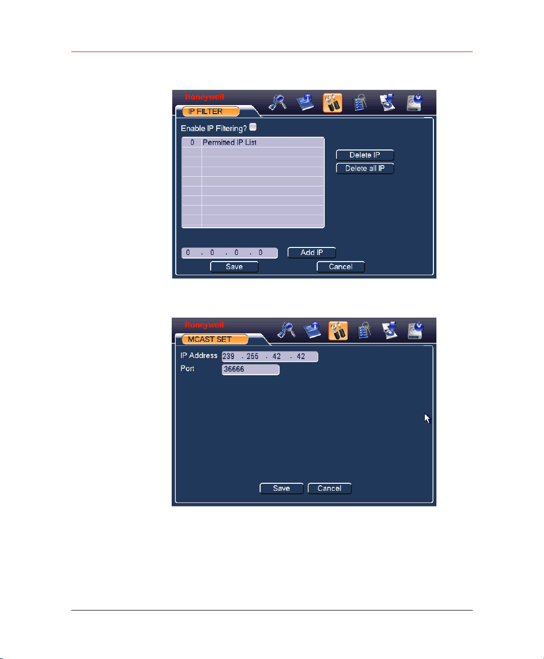
Understanding of Menu Operations and Controls
Figure 6-8 IP FILTER
• MCAST SET: Set multi cast. Click it to open the following window:
Figure 6-9 MCAST SET
56
After all the setups please click save button, system goes back to the
previous menu.
This series DVR is suitable for ATM use. System can overlay card number,
transaction time and etc on the monitor or playback window (Need
protocol support). System also supports search by transaction information
and card number.
Page 69

Honeywell
PPPoE Connection
Enable PPPoE function and then input “PPPoE name” and “PPPoE
password” you get from your ISP (Internet service provider).
Click Save button, you need to restart to activate your configuration.
After rebooting, IP camera will connect to the internet automatically. The
IP in the PPPoE is the dynamic value.
Web visit via PPPoE
There are two ways.
a. visit via current IP
After DVR connected with Internet by PPPoE, please get your device’s
current IP in Figure 6-7. Now you can visit this IP camera via this IP.
b. Visit via DNS
You need a PC of fixed IP in the internet and there is the DDNS software
running in this PC. In other words, this PC is a DNS (domain name server).
In network DDNS, input your PPPoE name you get from you IPS and
server IP (PC with DDNS ) . Click save button and then reboot system.
Click save button, system prompts for rebooting to get all setup activated.
After rebooting, open IE and input as below:
http://(DDNS server IP)/(virtual directory name)/webtest.htm
e.g.: http://10.6.2.85/DVR _DDNS/webtest.htm.)
Now you can open DDNSServer web search page.
NTP
You need to install SNTP server (Such as Absolute Time Server) in your
PC first. In Windows XP OS, you can use command “net start w32time” to
boot up NTP service.
In
Figure 6-7, select NTP and then click properties button. You can see
the following interface.
57
Page 70
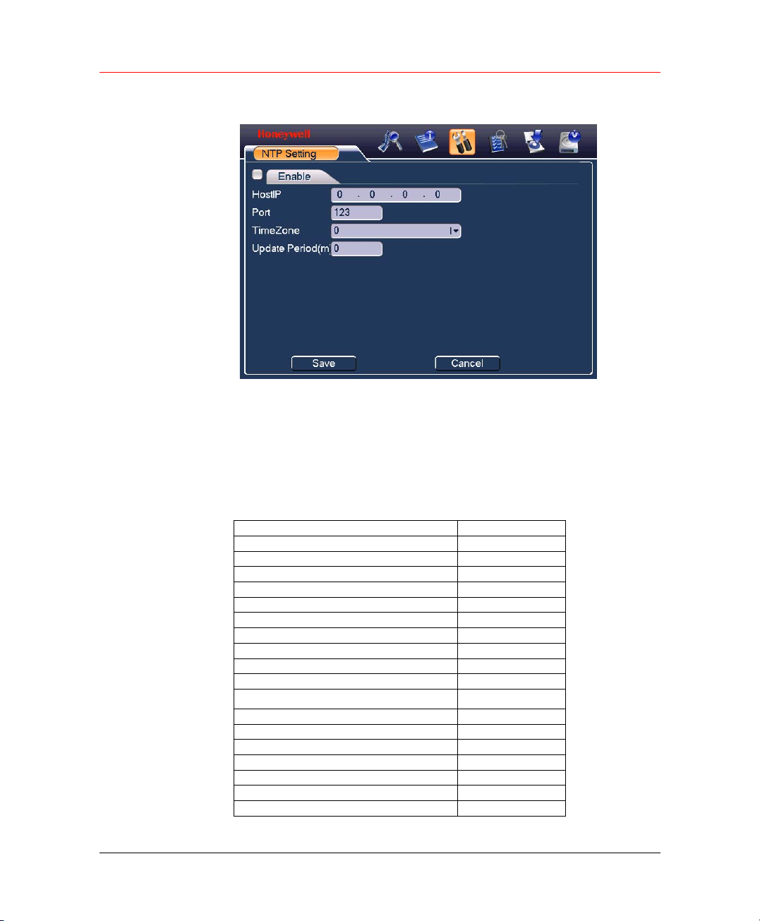
Understanding of Menu Operations and Controls
Figure 6-10 NTP Setting
• Host IP: Input your PC address.
• Port: This series DVR supports TCP transmission only. Port default
value is 123.
• Update interval: minimum value is 15(Unit: minute).
• Time zone: select your corresponding time zone here.
Here is a sheet for your time zone setup.
City /Region Name Time Zone
London GMT+0
Berlin GMT+1
Cairo GMT+2
Moscow GMT+3
New Deli GMT+5
Bangkok GMT+7
Beijing (Hong Kong) GMT+8
Tokyo GMT+9
Sydney GMT+10
Hawaii GMT-10
Alaska GMT-9
Pacific Time(P.T) GMT-8
American Mountain Time(M.T) GMT-7
American Central Time(C.T) GMT-6
American Eastern Time(E.T) GMT-5
Atlantic Time GMT-4
Brazil GMT-3
Middle Atlantic Time GMT-2
58
Page 71
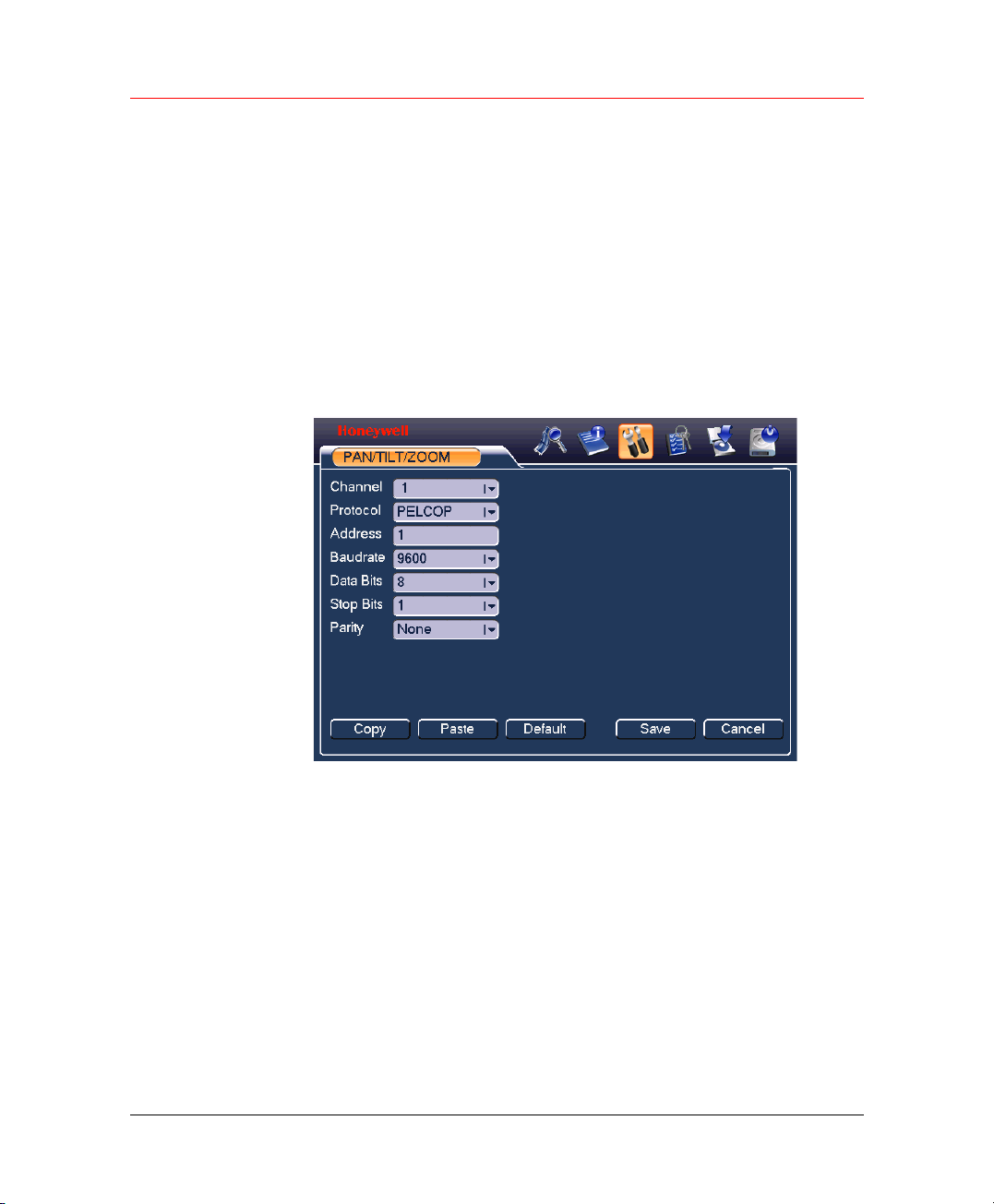
Alarm
Detect
Pan/Tilt/Zoom
Honeywell
Please refer to Alarm Setup and Alarm Activation on page 38.
Please refer to Detect on page 33.
The pan/tilt/zoom setup includes the following items. Please select
channel first.
Figure 6-11 PAN/TILT/ZOOM
• Protocol: select corresponding PTZ protocol such as PELCOP.
• Address: input corresponding PTZ address.
• Baud rate: select baud rate.
• Data Bits: select data bit.
• Stop Bits: select stop bit.
• Parity: there are five choices: none/odd/even/mark/space.
After all the setups please click Save button, system goes back to the
previous menu.
For detailed setup, please refer to
Preset/Patrol/Pattern/Scan on page 44.
59
Page 72
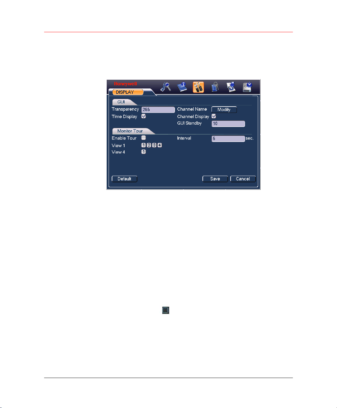
Understanding of Menu Operations and Controls
Display
Display setup interface is shown as below.
Figure 6-12 DISPLAY
• Transparency: Here is for you to adjust transparency. The value
ranges from 128 to 255.
• Channel name: Here is for you to modify channel name. Please note
all your modification here only applies to DVR local end. You need to
open web or client end to refresh channel name.
• Time display: You can select to display the time or not.
• Channel display: You can select to display the channel name or not.
• Enable tour: activate tour function.
• Interval: Input proper interval value here. The value ranges from 5-
200 seconds. In tour process, you can use mouse or click Shift to
turn on window switch function.
• View1/4: System support 1/4 window tour.
60
Please highlight icon
After all the setups please click Save button, system goes back to the
previous menu.
to select the corresponding function.
Page 73
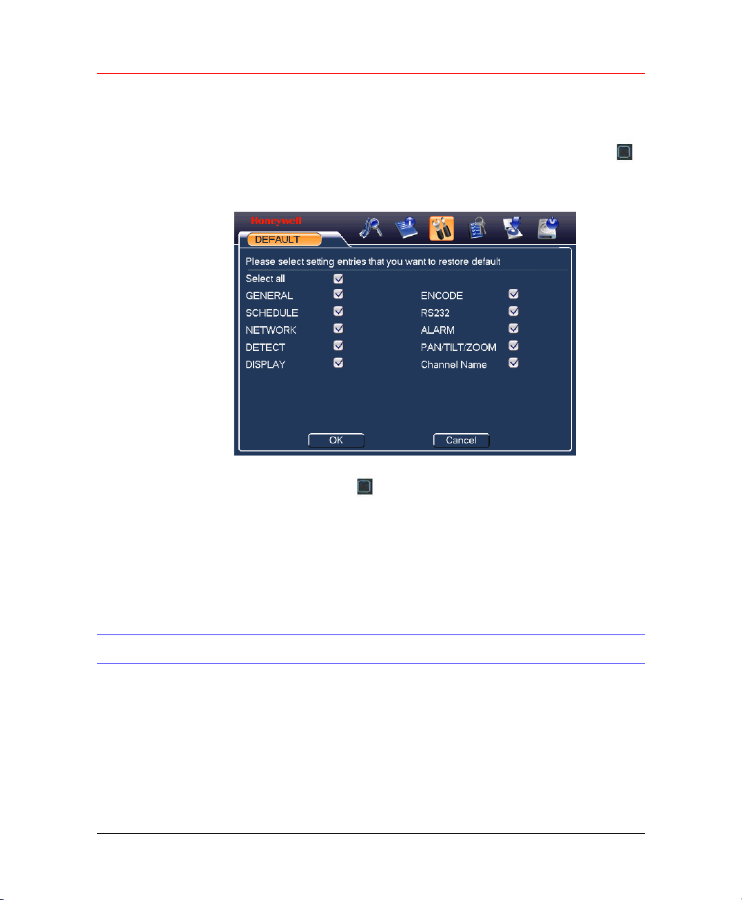
Default
Honeywell
Click default icon, system pops up a dialogue box. You can highlight
to restore default factory setup.
Figure 6-13 DEFAULT
Search
Please highlight icon
After all the setups please click Save button, system goes back to the
previous menu.
Warning!
System menu color, language, time display mode, video format, IP
address, user account will not maintain previous setup after default
operation!
Please refer to Search & Playback on page 26.
to select the corresponding function.
61
Page 74
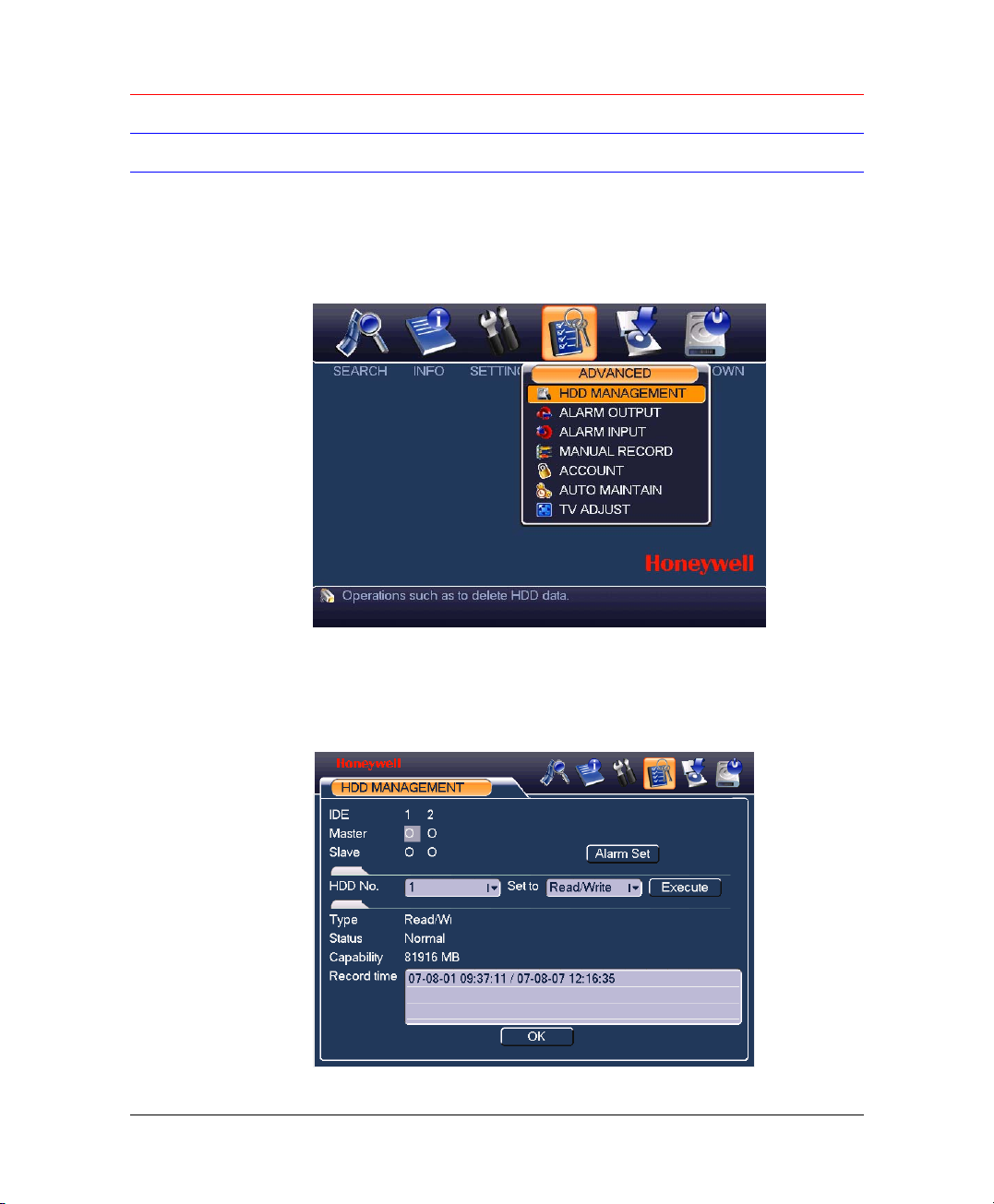
Understanding of Menu Operations and Controls
Advanced
Click advanced icon in the main window, the interface is shown as below.
There are totally seven function keys: HDD management, alarm output,
alarm input, manual record, account, auto maintain and TV adjust.
Figure 6-14 ADVANCED
HDD Management
Here is for you to view and implement hard disk management.
Figure 6-15 HDD MANAGEMENT
62
Page 75
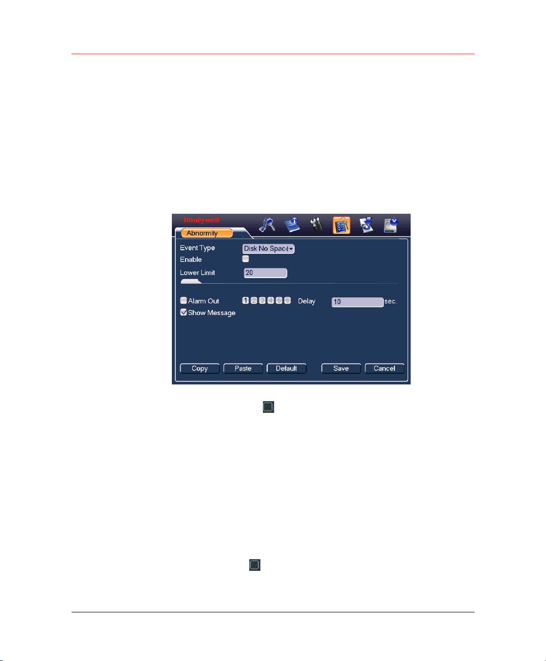
Honeywell
You can set proper mode for each hard disk from the dropdown list.
When you use redundant function, you can set one or more redundant
HDD(s).
Please note you need to set at least one read-write disk, otherwise system
will not record video. For detailed information you can refer to
Setup (Schedule) on page
After all the setups please click Save, system needs to reboot to get all
the modification activated.
Click Alarm Set button, the interface is shown as below.
Figure 6-16 Abnormity
30.
Record
Alarm Output
Please highlight icon
You can enable one or more alarm setups. The lower limit ranges from 1%
to 99%. Alarm channel number ranges from 1 to 6. Delay value is from 0
to 240 seconds.
Please note when HDD capacity is not full system only alarms once!
After all the setups please click Save button, system goes back to the
previous menu.
Here is for you to set proper alarm output.
Highlight the icon
to select the corresponding function.
to output the alarm of this channel.
63
Page 76
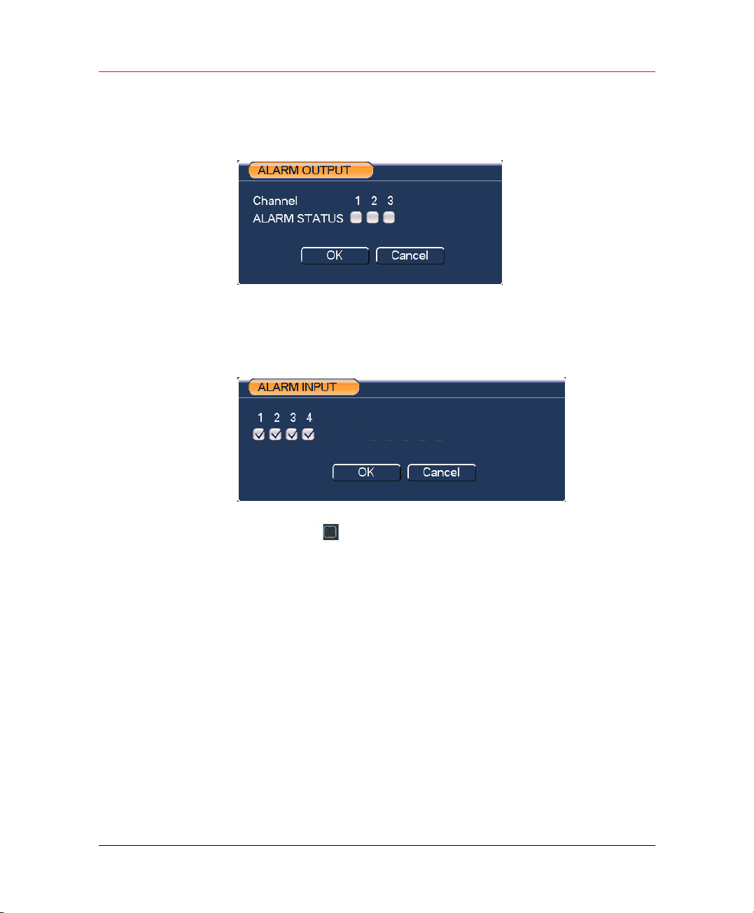
Understanding of Menu Operations and Controls
After all the setups please click OK button, system goes back to the
previous menu.
Figure 6-17 ALARM OUTPUT
Alarm Input
Here is for you to set alarm input.
Figure 6-18 ALARM INPUT
Highlight icon
After all the setups please click save button, system goes back to the
previous menu.
Manual Record
Please refer to Manual Recording on page 25.
Account
Here is for you to implement account management. Here you can:
• Add User
• Modify User
• Add Group
• Modify Group
64
to allow the channel to accept alarm input.
Page 77
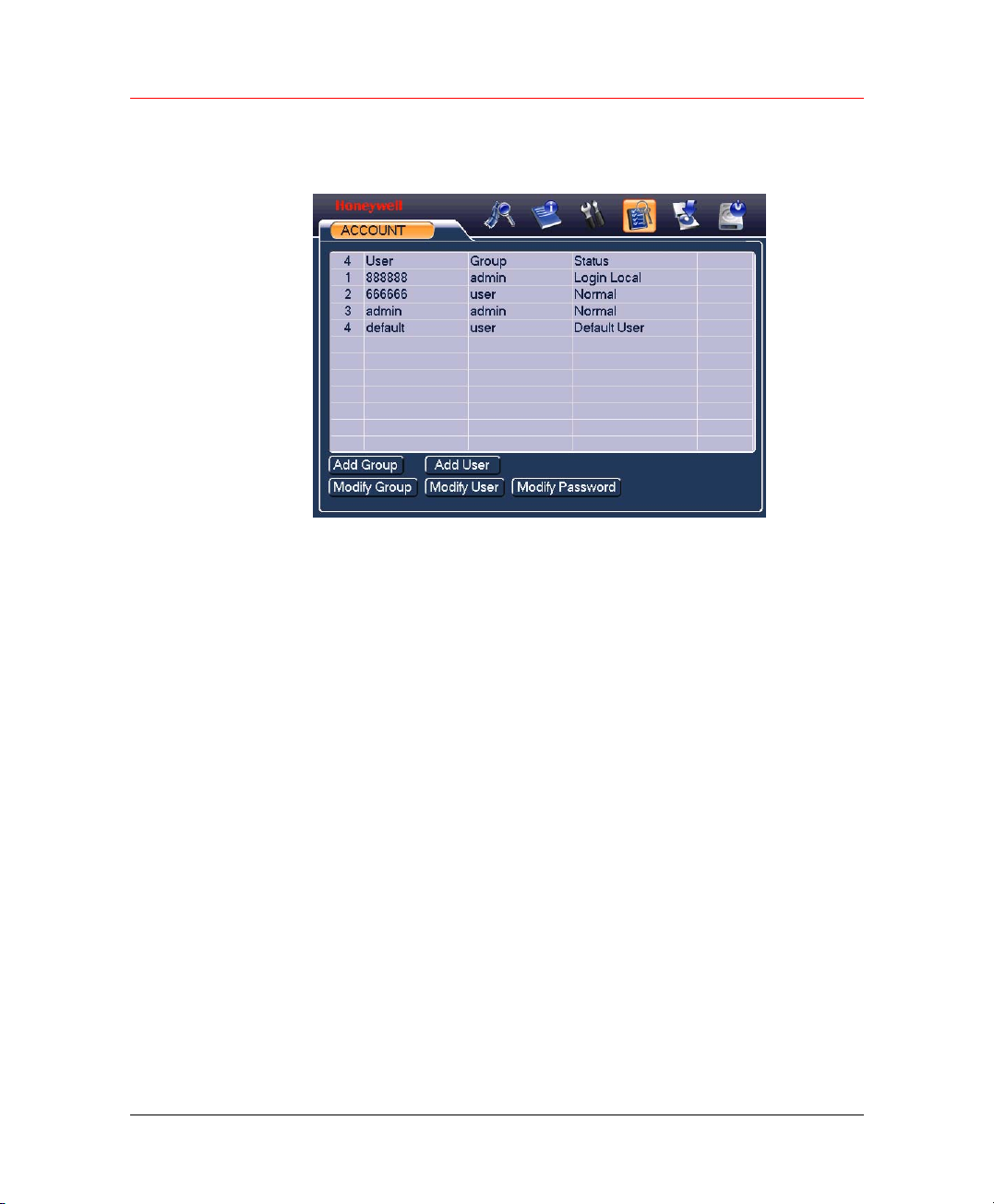
Honeywell
• Modify Password.
Figure 6-19 ACCOUNT
For account management please note:
• System account adopts two-level management: group and user. No
limit to group or user amount.
• For group or user management, there are two levels: admin and user.
• The user name and group name can consist of eight bytes. One
name can only be used once. There are four default users:
admin/888888/666666 and hidden user “default”. Except user
666666, other users have administrator right.
• Hidden user “default” is for system interior use only and can not be
deleted. When there is no login user, hidden user “default”
automatically login. You can set some rights such as monitor for this
user so that you can view some channel view without login.
• One user should belong to one group. User right can not exceed
group right.
• About reusable function: this function allows multiple users use the
same account to login.
After all the setups please click Save, system goes back to the previous
menu.
Auto Maintain
Here you can set auto-reboot time and auto-delete old files setup.
65
Page 78
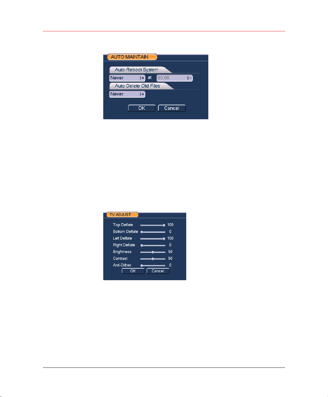
Understanding of Menu Operations and Controls
Figure 6-20 AUTO MAINTAIN
You can select proper setup from dropdown list.
Auto-Reboot System – the system will reboot termly.
Auto-Delete Old Files – the system will delete files create before a preset
time.
After all the setups please click OK button, system goes back to the
previous menu.
TV Adjust
Here is for you to adjust TV output setup.
Figure 6-21 TV ADJUST
66
Please drag slide bar to adjust each item.
After all the setups please click OK button, system goes back to the
previous menu.
Page 79
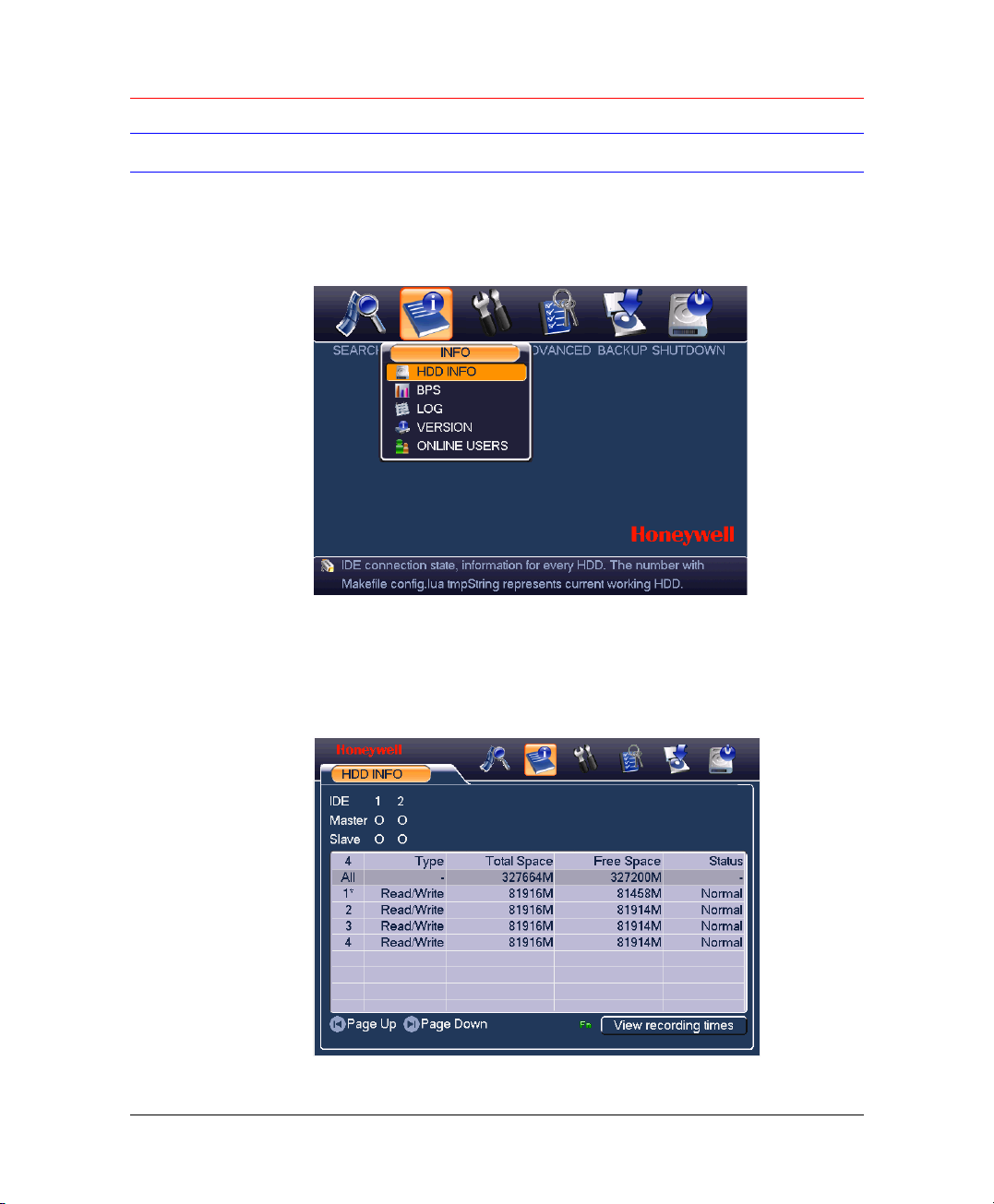
Info
Honeywell
Here is for you to view system information. There are totally five items:
HDD Info, BPS (data stream statistics), Log, version, and online users.
Figure 6-22 INFO
HDD Info
Here is to list hard disk type, total space, free space, video start time and
status.
Figure 6-23 HDD INFO
67
Page 80
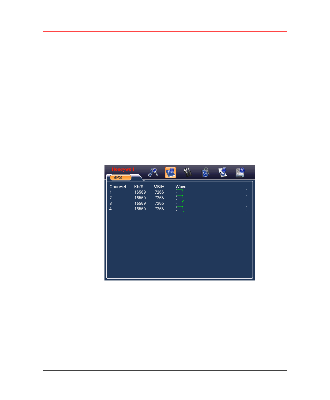
Understanding of Menu Operations and Controls
Please remove the broken hard disk before you add a new one.
Once there is a hard disk confliction, please check whether hard disk time
and system time is the same or not. Please go to SETTING Æ GENERAL
to modify system time. At last, reboot the system to solve this problem.
In IDE information column, ○means OK,X means error occurred 、-
means there is no disk.
The serial number after the disk information such as ○, which means it is
current working disk.
If disk is damaged, system shows as “?”.
BPS
Here is for you to view current video data stream (KB/s) and occupied
hard disk storage (MB/h).
Figure 6-24 BPS
Log
68
Here is for you to view system log file. System lists the following
information.
Page 81
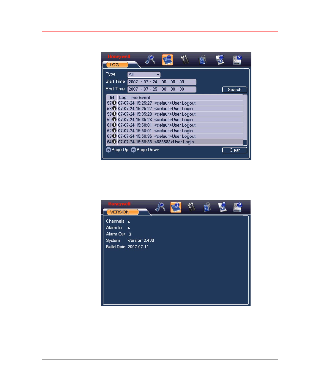
Version
Honeywell
Figure 6-25 LOG
Here is for you to view some version information.
Figure 6-26 VERSION
Online Users
Here is for you to manage online users.
69
Page 82

Understanding of Menu Operations and Controls
You can disconnect one user or block one user if you have proper system
right.
Figure 6-27 ONLINE USERS
Shutdown
70
Click Shutdown button, system pop up a dialogue box for you to select.
Logout menu user: log out menu. You need to input password when you
login the next time.
• Restart application: system will restart the application.
• Shutdown: system shuts down and turns off power.
• Restart system: system begins rebooting.
• Switch user: logoff the current user and switch to another user.
Page 83
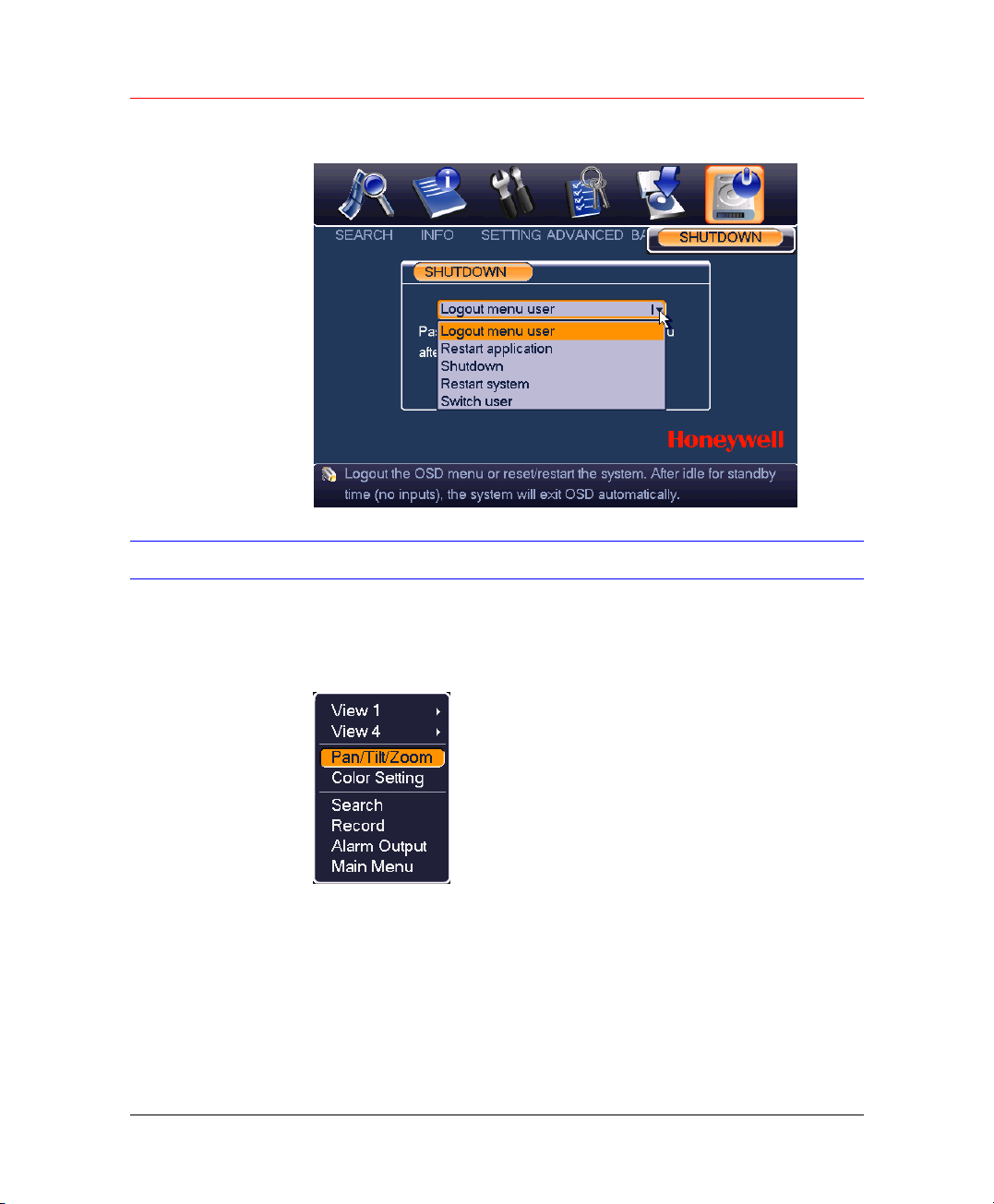
Figure 6-28 SHUTDOWN
About Auxiliary Menu
Honeywell
In the one-window surveillance mode, right click mouse (click FN in the
front panel). The interface is shown as below:
Figure 6-29 Right Click Menu
View 1: Select the video and play it in 1-window view.
View 4: Select the video and play it in 4-window view.
Pan/Tilt/Zoom: Open Pan/Tilt/Zoom window. See
Color Setting: Open the following window and adjust color settings.
Figure 5-23.
71
Page 84
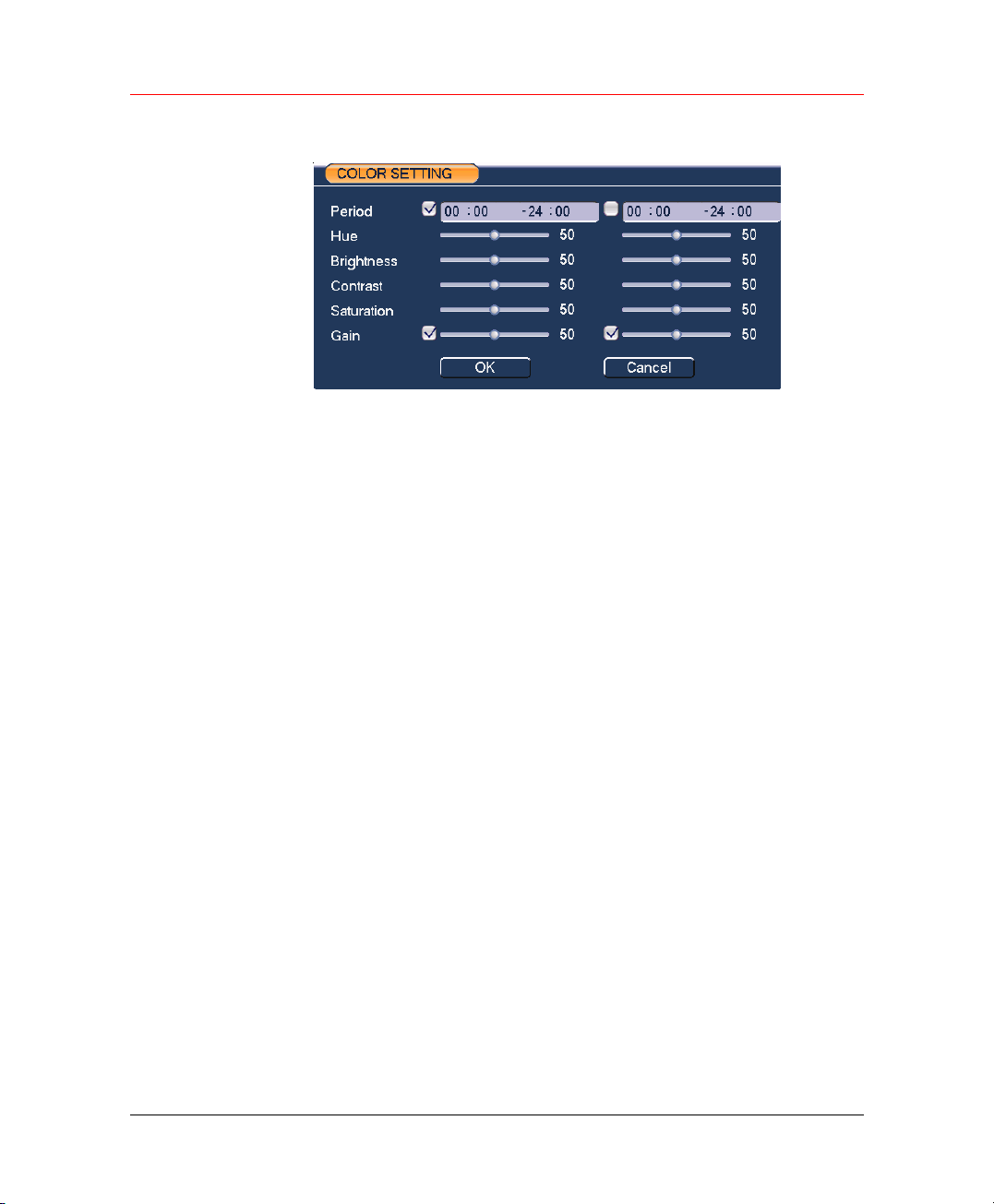
Understanding of Menu Operations and Controls
Figure 6-30 COLOR SETTING
Search: Open Search window. See Figure 5-6.
Record: Open Manual Record window. See Figure 5-5.
Alarm Output: Open Alarm Output window. See
Main Menu: Go to the main menu. See Figure 6-1.
Figure 6-17.
72
Page 85

7 Web Client Operation
Please note, all the operations in chapter seven is based on our HLVR4
DVR.
There might be slightly difference in the interface due to different series.
Network Connection
Before web client operation, please check the following items:
• Network connection is right
• DVR and PC network setup is right. Please refer to network
setup(main menu->setting->network)
• Use order ping ***.***.***.***(* DVR IP address) to check connection
is OK or not. Usually the return TTL value should be less than 255.
Honeywell
Login and Logout
Open IE and input DVR address in the address column. For example, if
your DVR IP is 10.1.27.200, then please input http:// 10.1.27.200 in IE
address column.
System pops up warning information to ask you whether install
webrec.cab control or not. Please click yes button.
If you can’t download the ActiveX file, please modify your settings as
below:
73
Page 86
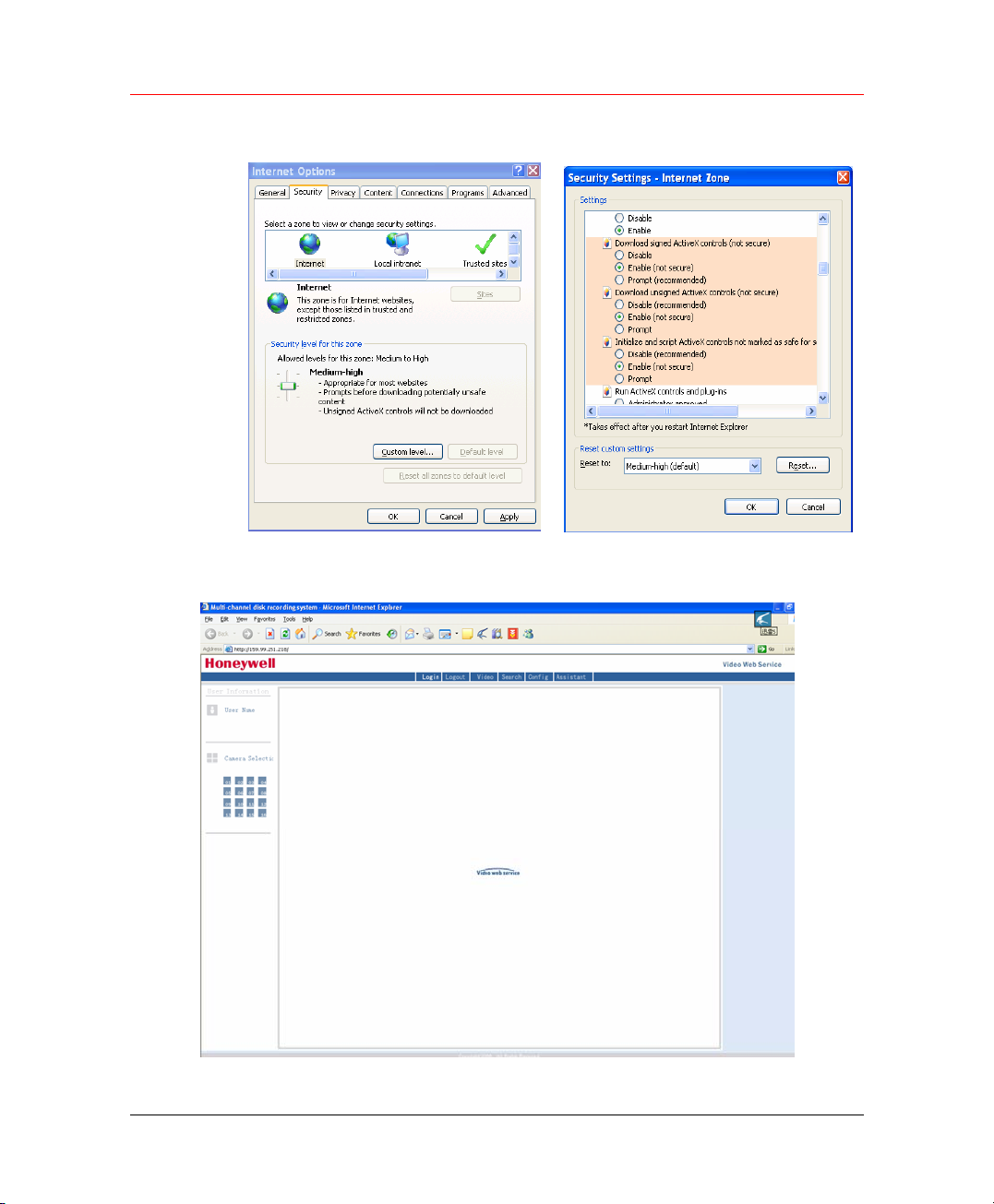
Web Client Operation
Figure 7-1 Security Settings
The Video Web Service interface is as below:
Figure 7-2 Web Service
74
Page 87
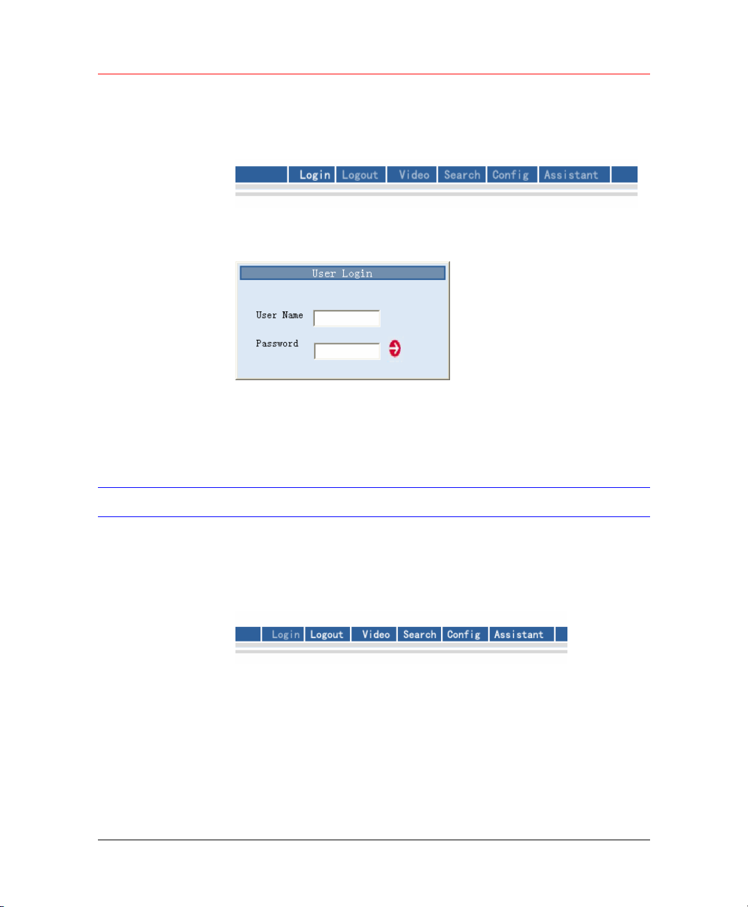
Honeywell
There are six function keys: Login, Logout, Video, Search, Config and
Assistant.
Figure 7-3 Function Keys
Click login the following interface will pop up.
Figure 7-4 Login
Please input your user name and password.
Default factory name is admin and password is admin.
Note: For security reasons, please modify your password after you first
login.
Go to Real-time Monitor Mode
There are three ways for you to go to real-time monitor mode.
• Select the channel number besides function key.
Figure 7-5 Function Keys
• In the above figure, click Video button then select real-time monitor,
click the channel number you want to view.
• In the main window, right click mouse, select the channel you want to
view from real-time monitor.
75
Page 88
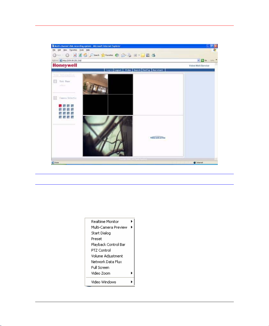
Web Client Operation
Figure 7-6 Real-time Surveillance
Video (Right Mouse Click Menu Operation)
After login, click Video or right click the mouse, the interface is shown as
below.
Figure 7-7 Right Click Menu
76
Page 89

• Real-time monitor: choose the channel you want to view.
• Start dialogue: click here to begin audio talk.
• Multi-camera preview: System supports various video preview
• Decode quality: there are totally four levels: general, good, better
• Playback control bar: here is for you to control playback.
• PTZ control: Here is for you to control PTZ movement. Before
• Volume adjustment: here is for you to adjust PC audio volume.
• Alarm setting: here is for you to set alarm input and alarm output.
• Network data flux: here is for you to view current data flux
• Full screen: enter into full screen display mode.
• Video zoom: there are four options:20%,40%,60%,80%,100%
• Video windows: Support 1/2/4 window display mode.
Real time Monitor
Honeywell
modes.
and best.
operate, please make sure you have selected right pan-title protocol
for DVR
Here is for you to select the channel you wan to implement real-time
monitor.
Multi-camera Preview
Here is for you to select view modes: 1/2/3/4/9/16.
Start Dialog
Click this button to enable audio talk function.
Playback Control Bar
Here is the playback bar when you are viewing video file.
Figure 7-8 Playback Bar
Record Stop Snapshot Fast
Backward
Pause Play
Fast
Forward
77
Page 90
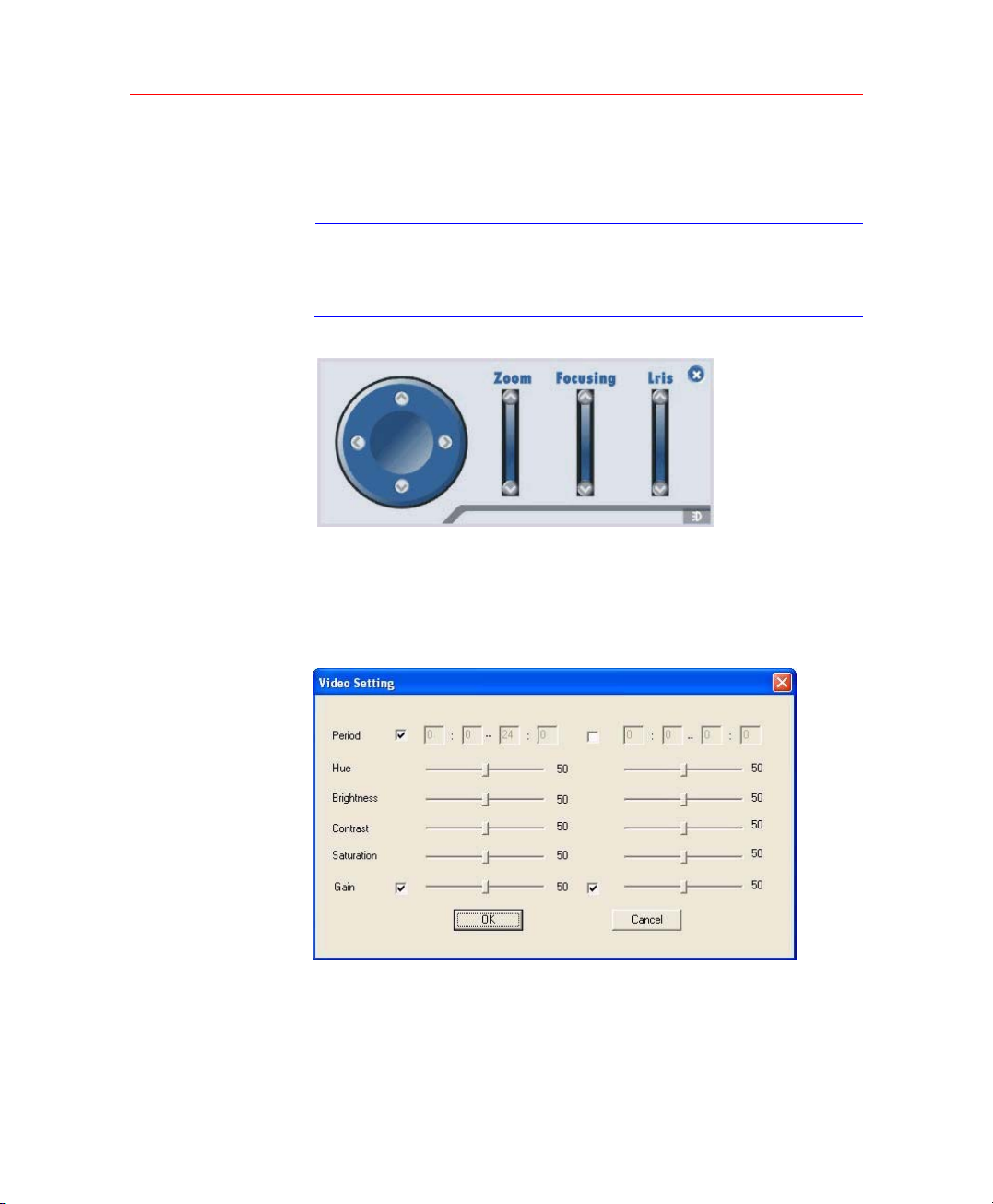
Web Client Operation
PTZ Control
Please click the corresponding direction arrow to adjust zoom, focus and
iris.
Note
Figure 7-9 PTZ control
Before you operate this function, please make sure you
have properly set PTZ protocol (Main menu->Setting->Pantilt Zoom).
Video Setting
Please the bar to adjust the level of each setting item and check needed
functions.
Figure 7-10 Video Setting
Network Data Flux
Here is to display the statistics of the network transmission data flux.
78
Page 91
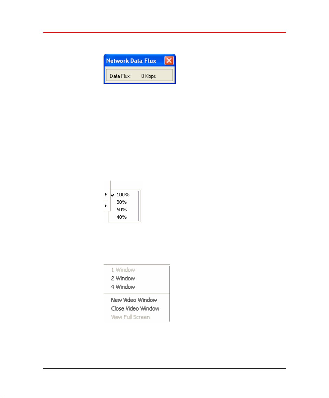
Full Screen
Video Zoom
Honeywell
Figure 7-11 Network Data Flux
There are two ways to view full screen monitor: One is to double click on
the current monitor window directly; the other is to select Full screen in the
right click menu items.
During multi-window state, choose one of the windows and double click for
full screen display.
There are four display ratios for you to choose: 40%, 60%, 80% and 100%.
Figure 7-12 Display Ratios
Video Windows
Here is for you to choose display mode.
Figure 7-13 Display Mode
79
Page 92
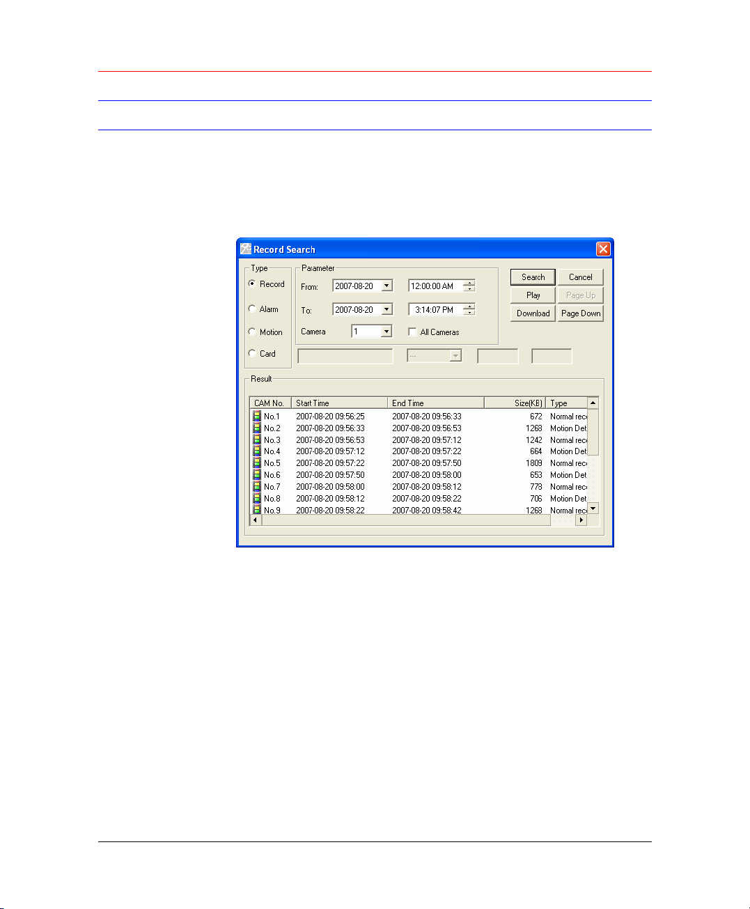
Web Client Operation
Search
Here you can select video type, channel number and time to search the
file you want.
Click search button, the interface is shown as below.
Figure 7-14 Record Search
Download
80
Please use page up/down key to view the search results.
Double click file name, you can view the file and system will automatically
backup the image in you installation directory.
In the search result interface, you can select one or more files to download
to your local PC.
The playback bar is displayed. See
You can select one or more files you want to download and then click
down load button. System pops up a dialogue box asking you specify
directory.
Figure 7-8.
Page 93
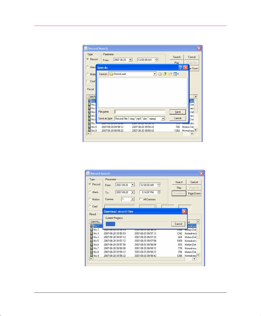
Honeywell
Figure 7-15 Download Files
Then you can input file name and click save to backup file in your local pc.
During the download process, there is a process bar for you reference.
Figure 7-16 Download in Progress
Download file name is usually made up of: file name +Channel N +date
+time.
81
Page 94
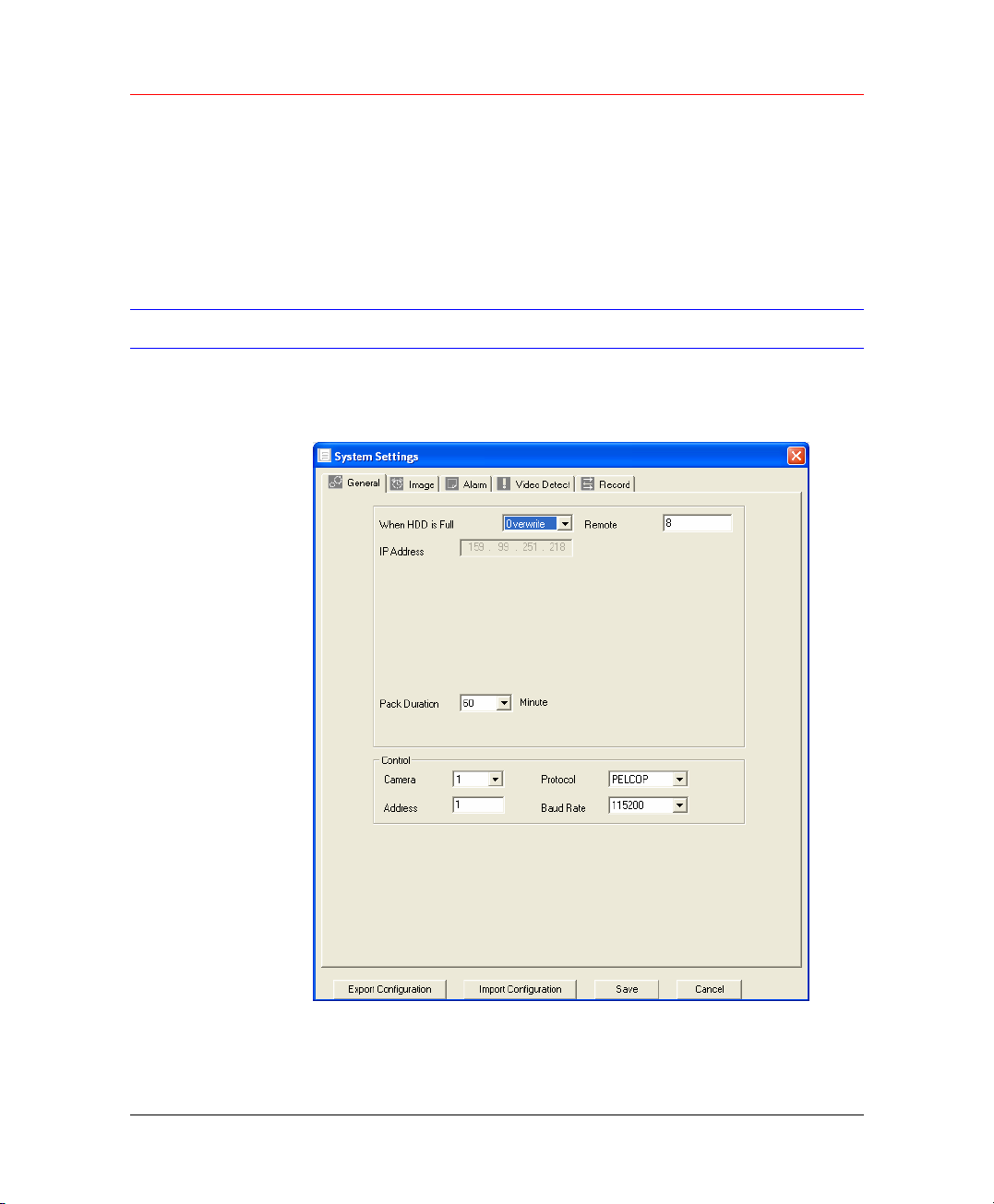
Web Client Operation
File extension name is .dav.
For example: file name a-0120021205071028.mp4 means:
• 01: channel 1
• 20021205: 5th December,2002
• 071028 :7 o’clock 10 minutes 28 seconds.
Configuration
Click configure button, there are totally seven function keys.
Figure 7-17 System Settings
82
Page 95
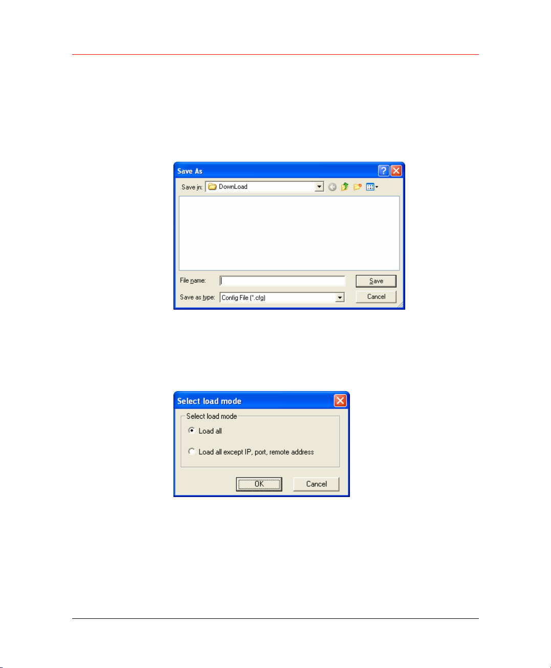
Load and Save Configuration
Save configuration
Click export configuration button in Figure 7-17.You can save current
configuration to a directory. The file extension name is CFG.
Figure 7-18 Save As CFG
Load configuration
Click import configuration button in Figure 7-17. You can draw a √ before
checkbox to load you previously backup file. Click Ok button and then
select file of extension name .CFG. Now you have updated system setup.
Figure 7-19 Select Load Mode
Honeywell
General
Click general button, the interface is shown as below.
83
Page 96
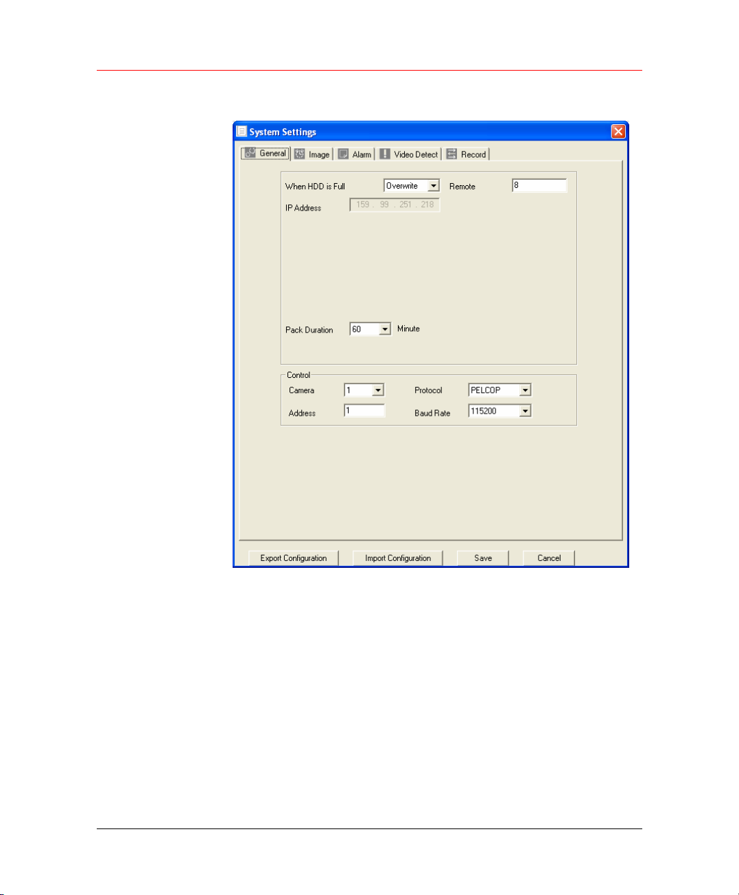
Web Client Operation
Figure 7-20 System Settings – General
Image
84
Here you can select file length, and choose overwrite the previous file or
stop recording when disk is full.
You can select channel number, protocol, address and baud rate to
control the lens or PTZ.
Click image button, the interface is shown as below.
Page 97
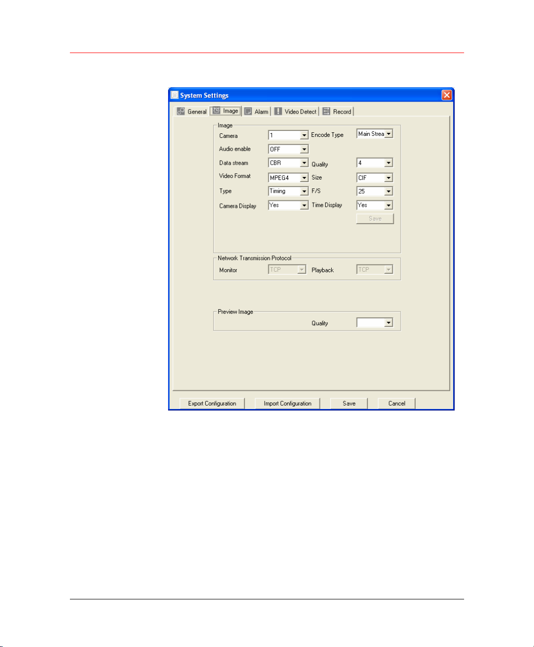
Figure 7-21 System Settings – Image
Honeywell
Here you can select the image quality and protocols for each channel.
Here you can set encode mode, quality and protocol for each channel.
You can select from the dropdown list.
• FPS (PAL): there are several options: 1/2/3/6/12/25. (Some series
DVR only support 25f/s PAL.)
• Data: there are two data modes: CBR/VBR.
• Quality: There are six levels. The different data flux occupies
different bandwidth and the transmission image qualities are also
different. Among them, level 6 needs the widest bandwidth and can
reveal the best image quality. Please note you setup here only
applies for image quality in web or client end.
85
Page 98
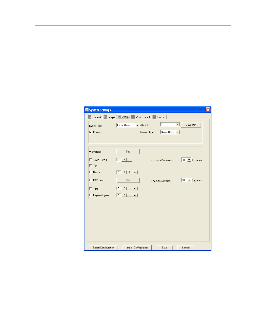
Web Client Operation
• Resolution: there are several resolutions for you. You can select
• Alarm when video loss: You can enable or disable alarm function
• Network transmission protocol: Select protocol for network playback
Alarm
Here is for you to choose record channel and output port.
Figure 7-22 System Settings – Alarm
from the dropdown list.
when alarm loss occurred.
and monitor. You can select from the dropdown list.
86
There are two alarm types: normal open or normal close.
Delay time ranges from 10 to 300 seconds.
You can draw a √ before the check box to enable record camera and
output port.
Page 99
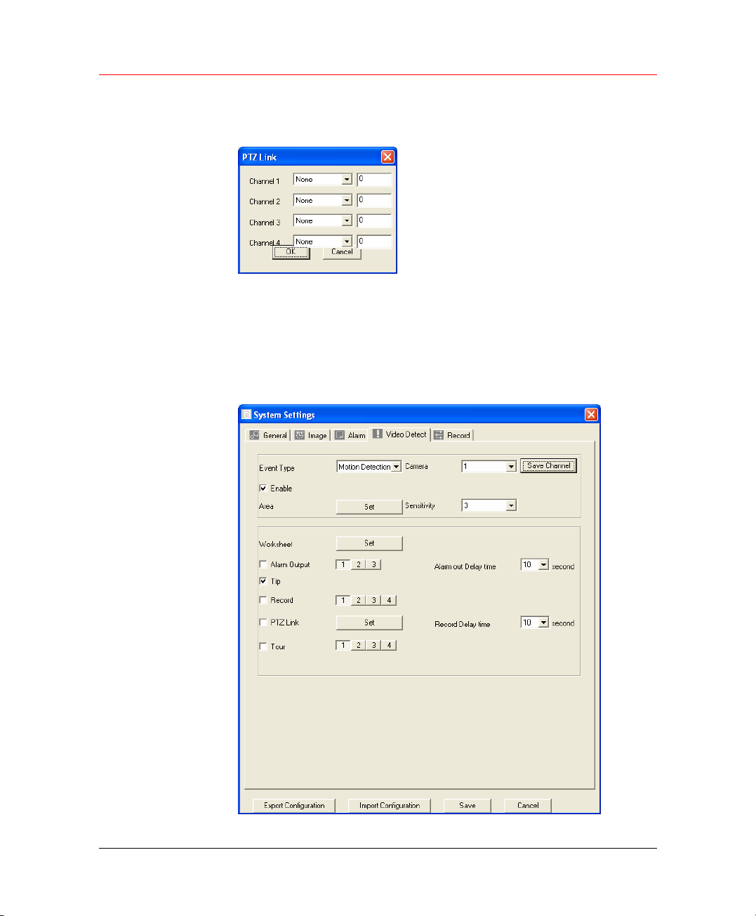
Video Detect
Honeywell
Click Set after PTZLink and the following window pops up:
Figure 7-23 PTZLink
Four options: None, Preset, Tour and Pattern.
Motion detection will take effect exclude the time you set to schedule
recording.
Figure 7-24 System Settings – Video Detect
87
Page 100
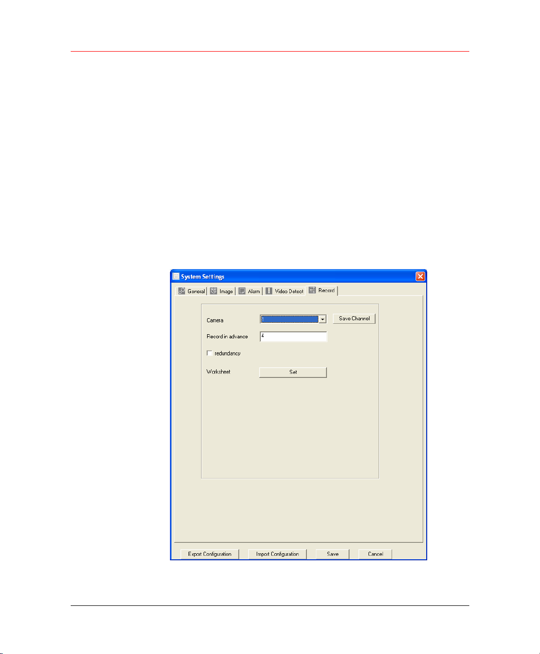
Web Client Operation
The blue area is the selected motion detection area.
Click Full screen or right click mouse to view the motion detection area in
full screen.
After setting the area you can Save channel or Clear the area.
Alarm output:Here you can enable alarm output channel. Please draw a
√ before the check box.
Please note if you want to set this channel as motion detection recording,
you need to turn off the schedule recording setup for this channel (Main
Menu->Setting->Schedule).
Record
In Record tab, you can configure pre-record settings and view worksheet
state.
Figure 7-25 Record
88
Click Set and the following window pops up:
 Loading...