

Page 1
Portable Air Conditioner
User Manual
HIGH
COOL
MID
DRY
LOW
FAN
o
C
TIMER
POWER
o
F
TIMER
SLEEP
SLEEP
WATER
FULL
Email: usinfo@jmatek.com
Web: www.jmatek.com
HL10 Series / Série / Serie: HL10CESWW, HL10CESWK, HL10CESWG, HL10CESWB
HL12 Series / Série / Serie: HL12CESWW, HL12CESWK, HL12CESWG, HL12CESWB
HL14 Series / Série / Serie: HL14CESWW, HL14CESWK, HL14CESWG, HL14CESWB
Model / Modèle / Modelo:
HL14CHESWW, HL14CHESWK, HL14CHESWG, HL14CHESWB
Page 2

SAFETY
READ AND SAVE THESE INSTRUCTIONS
IMPROPER HANDLING CAN CAUSE SERIOUS DAMAGE TO PEOPLE
AND TO THE APPLIANCE. IN CASE THERE IS ANY INCONSISTENCY
OR CONFLICT BETWEEN THE ENGLISH VERSION AND ANY OTHER
LANGUAGE VERSION OF THE CONTENT OF THIS MATERIAL, THE
ENGLISH VERSION SHALL PREVAIL.
WARNING:
•
DO NOT operate the unit with a damaged plug or loose wall outlet. If
the power cord is damaged, it must be replaced by the manufacturer or
an authorized service agent.
•
DO NOT cover the air intake and exhaust when in use.
•
This appliance is not intended for use by children. Children should be
supervised and should not play on or around the appliance.
•
DO NOT place objects on or sit on the unit.
•
Always turn off and unplug the unit when cleaning or servicing.
•
If service is needed contact an authorized service agent.
•
Unplug the unit when stored or not in use.
•
DO NOT run the power cord under carpeting and rugs.
•
Use caution to prevent tripping on cord.
•
DO NOT use in areas where gasoline, paint or other flammable goods
are stored.
•
Basic safety precautions should always be followed when using
electrical appliances.
EN
Page 3

SAFETY
This household appliance has been manufactured for use in domestic
•
environments and should not be used for other purposes.
•
Only use the installation kit provided to install this unit. DO NOT attempt
to extend the exhaust hose or install this unit using other methods other
than that provided in this manual. Improper installation could void any
existing warranties. Contact Customer Support for assistance if
required.
•
DO NOT use an extension cord with this unit.
EN
Page 4
THANK YOU
Congratulations on your purchase of this versatile Honeywell Portable Air Conditioner.
USER TIPS
Honeywell Portable Air Conditioners are ideal for spot cooling. The compressor, condenser and
evaporator are housed in a compact unit. The air is filtered, dehumidified and cooled while a flexible air
outlet hose sends heat outside. The air conditioner includes a window venting kit.
No permanent installation is needed. The unit is easy to move from room to room and offers a truly
flexible air conditioning solution.
Auto Evaporation System - The unit automatically evaporates the condensate through the air
outlet hose. There is no need to empty the drainage tank except in very humid conditions.
Read and follow the instructions carefully.
USER TIPS
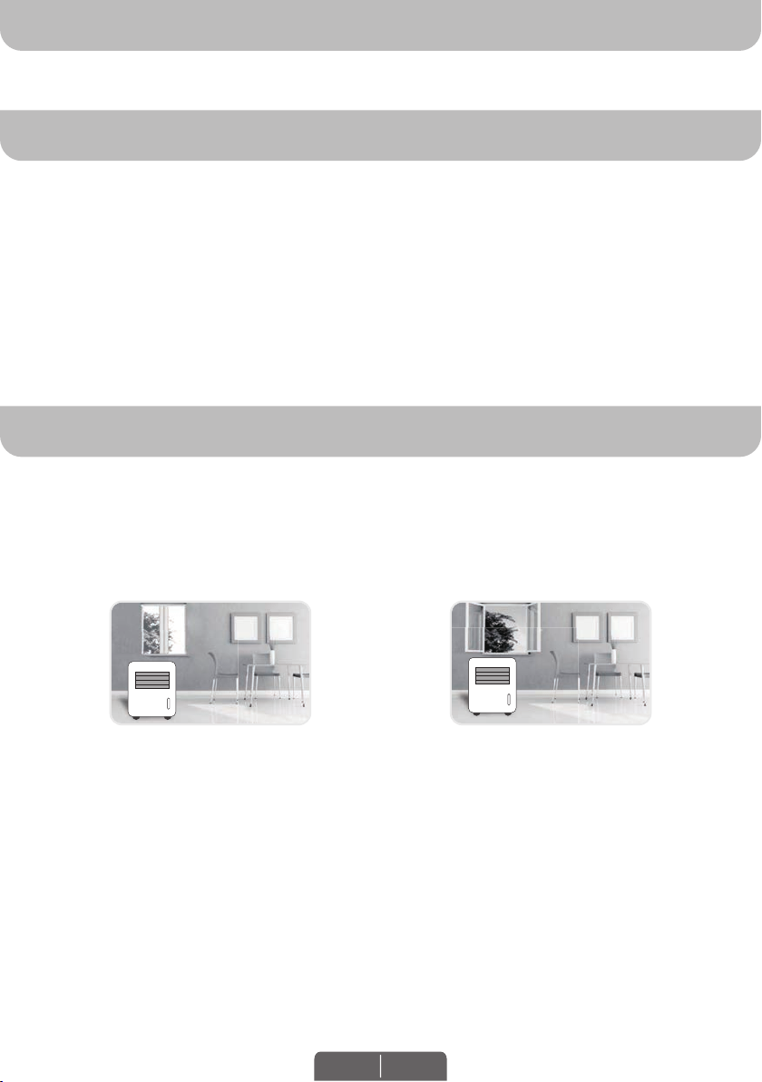
To ensure optimal efficiency of the product, keep doors and windows closed when it is used as an air
conditioner or dehumidifier. If the product is being used with the fan function only, an open window could
improve air circulation.
Cooling and Dehumidifying Operation Fan Operation
Important:
Before installing the unit, place it UPRIGHT for 1 hour before use to allow the refrigerant to stabilize.
Before installing the unit, place it UPRIGHT for 1 hour before use to allow the refrigerant to stabilize.
Manually adjust the air vent located at the top of the unit to adjust the direction of air flow.
Air outlet automatically opens when the unit is turned on, and automatically closes when the unit is
turned off. Manually adjust the air vent located at the top of the unit to adjust the direction of air flow.
Follow installation instructions to set up the unit.
•
Plug the unit into a properly grounded circuit. DO NOT plug into an extension cord.
•
EN 1
Page 5
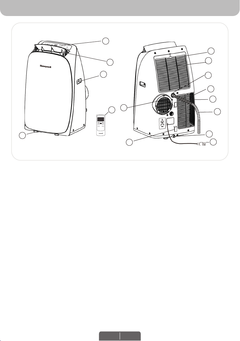
PARTS DESCRIPTION
10
10
1
8
4
1)
Control Panel
Control Panel
1)
Air Outlet
(Incl. Signal Receptor)
2)
2)
Handle
Air Outlet
3)
3)
Casters
Handle
4)
4)
Remote Control
Casters
5)
5)
Exhaust Hose Connector
Air Filter
6)
6)
Cord Winder
Back Grill
7)
Upper Grill
8)
Upper Air Filter
9)
2
3
9
10
11
12
6
5
ENC/APAG
VEL.MODO
DORMIR
TIEMPO
13
14
7
Exhaust Hose Connector
7)
Upper Rubber Drain Plug
10)
Power Supply Cord
8)
(Dehumidifying Mode)
Remote Control
9)
Lower Air Filter
11)
Lower Drain Plug with Plastic Cap
10)
Lower Grill
12)
(Air Conditioning Mode)
Drain Tube
13)
Upper Drain Plug (De-humidifier Mode)
11)
(For Continuous Drain)
Lower Rubber Drain Plug
14)
(Air Conditioning Mode)
Power Supply Cord
15)
15
EN 2
Page 6

INSTALLATION
Plastic Pin
Plastic Hose:
Dia. 5" (12.7cm)
Length: 12" to 47" (30cm to 120cm)
It is important that the installation instructions below are followed for successful installation of this
portable air conditioner. Please call Customer Support if you have any difficulties or queries regarding
these installation procedures.
Installation
1.
Window Bracket Kit.............................
2.
Window Bracket Panel Adapter...........
3.
Plastic Pin............................................
4.
Hose Connector..................................
5.
Plastic Hose........................................
Kit:
6. Drain Tube (refer to Continuous
Draining for Dehumidifier Mode)..........
1 Set
2 Half Pieces
1 Piece
1 Piece
2 Pieces
1 Piece
1 Piece
1 Piece
1
1
5
Installation Steps:
1. Install the plastic hose with window bracket adapter and hose connector on both sides.
Locate and snap the 2 half pieces of the Window Bracket Panel Adapter securely together. Install
Ensure proper fit on both ends.
onto the plastic hose by rotating anti-clockwise over the plastic hose. Install and rotate (anti-clock-
2
x 1
2
x 1
x 2
5
3
3
x 1 x 1
x 2 x 1
6
x 1
wise) the hose connector over the opposite end of the plastic hose. Ensure secure fit on both ends.
Adjust the window bracket as per width or
2. Adjust the window bracket as per width or
height of your window and insert the plastic
height of your window and insert the plastic
pin to fix at the desired position.
pins to fix at the desired position.
There is a hole where the Plastic Hose will be
3. Connect the plastic hose to the hose
connector on back of the unit.
Push-in until it is locked in place.
Slide-in the hose connector downwards
until it is locked in place.
inserted later. Make sure this hole is not
blocked.
Plastic Pin
Plastic Pin
4
4
x 1x 1
x 1
Hole for Plastic Hose20" to 47" (50.5cm to 119cm)
26.6", 33.1" to 49.6"
(67.5cm, 84cm to 126cm)
Hole for Window Bracket
Panel Adapter & Plastic Hose
Note:
After setting the window bracket to the size of your
window, please remove it from the window and
follow the instructions below.
Connect the window bracket to the window
4. Connect the window bracket to the opposite
bracket panel adapter.
end of the plastic hose.
Ensure that all connections are tight and
installed properly.
Plastic Hose:
5.9" (15cm)
Dia. 5" (12.7cm)
14.2" to 47.2" (36cm to 120cm)
Length: 12" to 47" (30cm to 120cm)
5. Connect the window bracket to the window.
6. The Portable Air Conditioner is now ready to use.
EN 3
Page 7

INSTALLATION (CONTINUED)
IMPORTANT:
• Do not replace or lengthen the exhaust hose as this could cause the unit to malfunction.
50 cm / 20”
MIN 55.5 cm
55.5 cm / 22”
110 cm / 43”
MIN. 36 cm / 14”
MAX. 102 cm / 40”
RECOMMENDEDNOT RECOMMENDED
WARNING: Any warranties included with this product will be voided if an extra extension hose is added
to the originally provided installation kit or if the installation is performed differently than the manufacturer's instructions, without proper consultation. Please contact Customer Support for help with installation
procedures if needed.
•
The supplied exhaust hose has a diameter of 5 inches (12.7cm) and can be extended from 12 inches
The supplied exhaust hose has a diameter of 5.9 inches (15 cm) and can be extended from 14.2
to 47 inches (30cm to 120cm).
inches to 47.2 inches (36 cm to 120 cm).
•
Do not bend (to the extent shown below) the exhaust hose. A bent hose will block exhaust air and
cause the unit to malfunction or shut-off.
•
Make sure the back of the unit is at least 50 cm / 20 inches away from the wall. Do not place the unit
in front of curtains or drapes as this could obstruct the airflow.
USE & OPERATION
TOUCH SCREEN CONTROL PANEL
CONTROL PANEL
Model without Heat ModeModel with Heat Mode
(2) (3)(4) (5)(6)(1)
COOL
(1)
Timer Control
(4)
Mode Control
HIGH
MID
LOW
DRY
FAN
HEAT
/ Sleep Control
o
C
o
F
POWER
TIMER
TIMER
SLEEP
SLEEP
WATER
FULL
(2)
Fan Speed Control
(5)
Power Control / Standby Mode
POWER CONTROL
The Power Control turns the unit on and off. When the unit is plugged in, this button lights up indicating
The Power Control turns the unit on and off. When the unit is plugged into an appropriate electrical
it is in a Standby Mode ready to be switched on anytime.
outlet, the POWER indicator light will illuminate red indicating the unit is in a Standby Mode, ready to be
switched on at anytime. The air vent will automatically open when the unit is turned ON and automatically close when unit is turned OFF.
EN 4
(2) (3)(4) (5)(6)(1)
COOL
HIGH
MID
DRY
LOW
FAN
(3)
(6)
o
C
o
F
Timer / Temperature Set Controls
Indicator Lights
Warning Light (when flashing)
POWER
TIMER
TIMER
SLEEP
SLEEP
WATER
FULL
*Applicable for models with Heating feature only.
Page 8

USE & OPERATION (CONTINUED)
FUNCTION BUTTONS (CONTINUED)
MODE CONTROL
4 settings: Cool, Heater*, Dehumidify & Fan.
Settings: COOL, DRY and FAN.
Settings: COOL, DRY, FAN and HEAT*.
3 settings: Cool, Dehumidify, Fan.
The corresponding indicator light will illuminate to indicate the current mode setting.
• Cooling Mode
Air Conditioning Mode (COOL)
Adjust fan speed and air temperature to suit your desired comfort level.
Temperature setting range is 16°C- 32°C (61°F- 89°F).
Temperature setting range is 16°C - 32°C (60°F - 90°F).
Dehumidifying Mode (DRY)
•
Fan speed is preset to LOW.
Air is dehumidified as it passes through the unit, without being in full cooling mode. If room temperature is higher than 25°C (77°F) fan speed can be adjusted; otherwise fan speed is preset to LOW.
Note: If the unit will be used mainly as a dehumidifier, do not connect the exhaust hose. Continuous
drainage is then necessary (refer to Continuous Draining for Dehumidifier Mode).
• Fan Mode (FAN)
For air circulation without air conditioner cooling.
•
Heating Mode* (HEAT)
•
In this mode, the desired temperature can be set between 16°C - 32°C (60°F - 90°F). When in heating
When heating mode is selected the indicator light will shine. Heating is activated only when the ambient
mode condensation must be drained from the lower drain plug.
temperature is below 25°C (77°F). In this mode, the desired temperature can be set between 16°C- 25°C
(61°F- 77°F).
Note: The air exchange hoses must vent outside the room when using heating mode.
• Sleep Mode (SLEEP)
When the Sleep Mode is activated in Air Conditioning mode, the set temperature will increase by 1°F
or 1°C after the first hour of cooling and will increase a further 1°F or 1°C after the second hour of
cooling. The unit will maintain this temperature for 5 hours. The set temperature will then reduce by
1°F or 1°C on the seventh hour and reduce a further 1°F or 1°C on the tenth hour. Sleep mode will
then deactivate automatically.
Note: The Sleep Mode can be deactivated during cooling mode by pressing any button at any time.
In Heating Mode*, the set temperature will reduce by 2°F or 2°C after the first hour of heating* and will
reduce a further 2°F or 2°C after the second hour of heating*. The unit maintains heating* at this
temperature for 5 hours. Then, the set temperature will increase 2°F or 2°C at the seventh hour and
will increase a further 2°F or 2°C on the tenth hour. Sleep mode will then deactivate automatically.
Note: The Sleep Mode can be deactivated during cooling or heating* mode by pressing any button at
any time.
*Applicable for models with Heating feature only.
EN 5
Page 9

USE & OPERATION (CONTINUED)
FUNCTION BUTTONS (CONTINUED)
FAN SPEED CONTROL
3 settings: High, Medium and Low.
TIMER CONTROL
The Timer is adjustable between 1 - 24 hours.
While the unit is turned on, press the timer button then press the ▼ or ▲ to select the number of hours
you would like the unit to continue to run. The unit will turn off automatically.
AUTO TURN OFF:
While unit is running, press the ▼ or ▲ button to select the number of hours you want the unit to run in
While unit is running, press the TIMER button and the display will flash. While the display is flashing,
air conditioning mode.
press the + or - button to select the number of hours you want the unit to turn OFF automatically.
AUTO TURN ON:
When unit is in a standby mode (plugged in with power light on), press the TIMER button and the display
When unit is in a standby mode (plugged in with power light on), then press the ▼ or ▲ button to select
will flash. While the display is flashing, press the + or - button to select the number of hours until you
the number of hours until you want the unit to automatically start running.
want the unit to turn ON automatically.
TEMPERATURE CONTROL
TEMPERATURE / TIMER SET CONTROLS
•
Used for adjusting the timer and thermostat.
•
The default display is room temperature.
In cooling mode, when + or - button is pressed, the set temperature is displayed and may be
•
In cooling mode, when ▼ or ▲ button is pressed, the set temperature is displayed and may be
adjusted. After 5 seconds the display will revert back to room temperature.
adjusted. After 10 seconds the display will revert back to room temperature. Temperature is only
Note: By pressing both + / - buttons at the same time, the display will toggle between Celsius and
adjustable in cool mode. The time is adjustable between 1~24 hours.
Fahrenheit.
Note: By pressing both ▼/ ▲ set buttons at the same time, the display will toggle between Celsius
and Fahrenheit.
WATER FULL LIGHT
WARNING LIGHT
Condensation may accumulate in the unit.
If the internal tank becomes full, the Power Control light will flash and the unit will not operate until the
If the bottom internal tank is full, the WATER FULL light will illuminate and an alarm will beep for 30
unit has been drained (refer Water Condensation Drainage).
seconds. The unit will not operate until the water has been drained from the bottom drain plug (refer to
Water Condensation Drainage).
After switching the air conditioner off, you must wait 3 minutes before switching it back on
again.
After switching the air conditioner off, the compressor will not start immediately.
You must wait about 4 minutes before it switches back on again.
EN 6
Page 10

USE & OPERATION (CONTINUED)
REMOTE CONTROL
The functions work the same as the portable air conditioner's Touch Screen Control Panel.
The functions work the same as the portable air conditioner's Control Panel.
All key functions can be accessed from the remote control.
Power Control
ON / OFF
Mode Control
Press this button to change the
operation mode
COOL DRY
In running mode: Auto switch off
In stand-by mode: Auto switch on
Press ▼ or ▲ button to adjust the
time setting for 1 hour intervals.
Fan Speed Control
• HIGH • MEDIUM • LOW
HEAT*
Timer Control
FAN
Note:
•
Battery Installation: Remove the cover on the back of the remote control and insert two AAA batteries
with + and - pointing in the proper direction according to the polarity markings.
Temperature / Timer Set
Used for adjusting the timer and temperature.
•
When ▼ or ▲ key is pressed in cool mode, the
When the ▼ or ▲ key is pressed, the set
•
set temperature is displayed and may be
temperature is displayed and may be
adjusted.
adjusted.
Timer setting is available from 1-24 hours by
•
pressing the key ▼ or ▲.
Fan Speed Control
Mode Control
• HIGH • MID • LOW
Press this button to change the operation mode
in the order of:
Sleep Control
Cool Dehumidify
ON / OFF
Heater*
Fan
*Applicable for models with Heating feature only.
Caution:
•
Use only two AAA or IEC R03 1.5V batteries.
•
Remove the batteries if the remote control is not in use for a month or longer.
•
All batteries should be replaced at the same time, do not mix with old batteries.
•
Do not mix alkaline, standard (carbon-zinc) or rechargeable (nickel-cadmium) batteries.
•
Properly dispose of used batteries.
This device complies with part 15 of the FCC Rules. Operation is subject to following two conditions: (1) this device may not cause harmful
interference, and (2) this device must accept any interference received, including interference that may cause undesired operation.
This equipment has been tested and found to comply with the limits for a Class B digital device, pursuant to part 15 of the FCC Rules. These limits
are designed to provide reasonable protection against harmful interference in a residential installation. This equipment generates, uses and can
radiate radio frequency energy and, if not installed and used in accordance with the instructions, may cause harmful interference to radio
communications. However, there is no guarantee that interference will not occur in a particular installation. If this equipment dose cause harmful
interference to radio or television reception, which can be determined by turning the equipment off and on, the user is encouraged to try to correct
the interference by one or more of the following measures:
• Reorient or relocate the receiving antenna.
• Increase the separation between the equipment and the receiver.
• Connect the equipment info an outlet on a circuit different from that to which the receiver is connected.
• Consult the dealer or an experienced radio/ TV technician for help.
Caution: Any changes or modifications not expressly approved by the party responsible for compliance could void the user’s authority to operate
the equipment.
EN 7
Page 11

CLEANING & MAINTENANCE
Appliance Maintenance:
1.2.Turn off the appliance before disconnecting the power supply.
Only clean the appliance with a soft dry cloth.
Air Filter Maintenance:
The air filter is to be cleaned every two weeks to maintain a cleaner
environment and air cooling efficiency. Please follow the below
instructions for cleaning the air filters:
Switch off and unplug the air conditioner from the electrical outlet.
1.
1.2.Turn off the appliance and remove the air filter.
Remove the Upper Filter/Grill and unscrew the Lower Filter/Grill and carefully remove.
2.
Rinse it in lukewarm water. After cleaning, dry in a shaded and
Gently wash using water and/or diluted liquid dishwashing detergent. Rinse thoroughly and gently
3.
cool place, then reinstall.
shake excess water from the filters.
Make sure the filters are dry before reinstalling.
Note: You may use a vacuum cleaner to remove dust.
Replace the Upper Grill onto the unit, and reinstall the Lower Grill with the screws.
4.
WARNING: DO NOT power or operate the Air Conditioner when cleaning or when any or both of the
Rear Grills are removed from the unit, or if there is a loose-fitting Rear Grill(s). DO NOT attempt to handle
or touch any of the parts or wiring inside the air conditioner after the Rear Grill(s) are removed from the
unit. Doing so can cause serious injury or electrical shock.
End of Season Storage & Maintenance:
If the appliance will not be used for a long time:
1.
Be sure to drain the left-over water condensation. Remove the lower drain plug and use a
shallow pan to collect the water (make sure to replace the drain plug when finished).
2.
To dry excess moisture, run the unit in Fan only mode for 30 minutes before storing.
3.
Turn off and unplug the air conditioner from the power supply.
4.
Remove the air filter and clean with water. Dry the air filter and then reinstall.
5.
Disconnecting the Window Installation Kit:
Remove the Plastic Hose from the unit.
Remove the Plastic Hose from the unit by pulling away from the unit at the same time.
•
Remove the Window Bracket, Window Bracket Panel Adapter and Hose Connector.
•
It is recommended to store the Window Kit parts in a bag together with the Remote Control and
•
placing them together with the air conditioner unit.
If needed, you can clean the Window Kit with a damp cloth and water before storing. Make sure all
•
parts of the Window Kit are dry before storage.
6.
Cover the air conditioner with a cloth/ plastic bag before storage, to protect from dust and scratches
collecting on the surface of the unit.
7.
It is recommended to coil the power cord before storing to ensure the cord is protected from bents
and creases.
8.
Store the air conditioner in a cool, dry place, away from direct sunlight.
EN 8
Page 12

WATER CONDENSATION DRAINAGE
Upper
Drain Plug
Plastic Cap
& Lower
Drain Plug
Drain Tube
WATER CONDENSATION DRAINAGE
When there is excess water condensation inside the unit, the air conditioner stops running and shows a
When there is excess water condensation inside the unit, the air conditioner stops running and shows a
warning light (the Power Control button flashes with a red light). This warning light indicates that the
warning light (the WATER FULL indicator illuminates with a red light). This indicates that the water
water condensation needs to be drained using the following procedures:
condensation needs to be drained using the following procedures:
Manual Draining for Cooling & Dehumidifier Mode
Manual Draining for Cooling, Heating* & Dehumidifier Mode
Manual Draining for AC & Dehumidifier Mode
Water may need to be drained in high humidity areas.
1.
Unplug the unit from power source.
Place a shallow pan under the lower rubber drain plug.
2.
Place a shallow pan under the lower drain plug.
See diagram.
Remove both the plastic cap and lower drain plug.
3.
Remove the rubber drain plug.
Water will drain out and collect in the shallow pan.
4.
After the water is drained, replace the rubber
After the water is drained, replace the lower drain plug
5.
drain plug.
firmly.
You can now turn on the unit.
6.
Continuous Draining for Dehumidifier Mode
While using the unit in dehumidifier mode, continuous
drainage is recommended.
1.
Unplug the unit from the power source.
2.
Remove the upper drain plug.
Remove the upper/lower rubber drain plug.
Some residual water may spill so please have a pan to
collect the water.
Connect the drain connector to a ¾” hose or standard
3.
Connect the drain tube (included) to the upper or lower
garden hose (not included).
drain (whichever is more convenient for your space).
See diagram.
The water can be continuously drained through the
4.
drain tube into a floor drain or bucket.
Replace the drain plug.
5.
You can now turn on the unit.
6.
Shallow Pan
(Not included)
Upper Rubber
Upper
Drain Plug
Drain Plug
Drain Tube (included):
Dia. 0.09" (0.22cm)
Length: 29.3" (74.5cm)
Plastic Cap
Lower
& Lower
Rubber
Drain Plug
Drain Plug
Drain Tube
*Applicable for models with Heating feature only.
EN 9
Page 13

TROUBLESHOOTING GUIDE
The following troubleshooting guide addresses the most common problems. If problems persist, call
customer service. Unplug and disconnect the appliance from the power source before attempting to
troubleshoot.
PROBLEM POSSIBLE CAUSE SOLUTION
The air conditioning
unit does not start
Runs only a short
while
Runs but not cooling
Will not run and Power
Will not run and
button is blinking
WATER FULL indicator
(water full indicator)
is on
No electricity.
•
Batteries in the remote control need
•
to be replaced.
The power cord is not properly
•
plugged in.
The safety LCDI plug has tripped
•
(USA / Canada / Mexico only).
The thermostat temperature setting
•
is too close to the room
temperature.
Air outlet is blocked.
•
There are tight bends in the air
•
exhaust hose.
A door or window is open.
•
The air filter is dirty.
•
The exhaust hose is detached.
•
Temperature setting is too high.
•
Air outlet or intake is blocked.
•
Room exceeds recommended size.
•
Large size or number of windows
•
are decreasing cooling effectiveness.
Excess water condensation inside
• Drain the water (refer to Water
the tank.
Check for power.
•
Change remote control batteries.
•
Remove and reconnect the
•
power cord.
Reset the safety LCDI plug, if
•
problem persists contact our
customer support (USA /
Canada / Mexico only).
Lower the set temperature.
•
Make sure the exhaust hose is
•
properly connected.
Connect exhaust hose as per
•
instructions on page 4.
Make sure the window or door
•
is closed.
Clean the air filter.
•
Reinstall exhaust hose properly
•
(refer to Installation section).
Reduce temperature setting.
•
Remove blockage.
•
Move unit to smaller room.
•
Cover windows with curtains or
•
blinds.
•
Condensation Drainage).
Heater* is not
switching ON
(This applies to
Portable Air
Conditioner models
with built-in Heating*
function only).
Heating* function not activated yet.
•
Temperature setting is too low.
The ambient temperature is too high.
Heating* is activated only when the
•
ambient temperature is below 25°C
(77°F).
*Applicable for models with Heating feature only.
EN 10
Check that the Heating* function
•
has been activated.
will be illuminated when the
Increase temperature setting.
Heater* is switched ON.
Switch on the Heating* function
•
when the ambient temperature
reaches below 25°C (77°F).
Page 14

JMATEK North America LLC
Mahwah, New Jersey 07495 USA
Email: usinfo@jmatek.com
Web: www.jmatek.com
Made in China
© 2016 JMATEK Limited. All rights reserved.
The Honeywell Trademark is used under license
from Honeywell International Inc.
Honeywell International Inc. makes no
representations or warranties with respect to this product.
This product is manufactured by Airtek Int'l Corp. Ltd.
(subsidiary of JMATEK Ltd.).
 Loading...