

Page 1

HJZTP/HJZTPX
Joystick Controller for
PTZ Cameras, DVRs, and Multiplexers
User Manual
900.0570 – September 2005 – Rev. 1.01
Page 2

ISSUE DATE REVISIONS
HJZMU001150
A March 2005 Initial Release.
B July 2005 Revised Model # (ECI 2003)
900.0570
1.00 August 2005 Revised Model #
1.01 September 2005
Revised cable qty. in package contents and added operation
with KD6i/HD6i in Maxpro Mode (EC03566)
Rev. 1.01 ii 900.0570
8-Sept-05
Page 3
FCC COMPLIANCE STATEMENT
Information to the User: This equipment has been tested and found to comply with the
limits for a Class A digital device, pursuant to part 15 of the FCC rules. These limits are
designed to provide reasonable protection against harmful interference when the
equipment is operated in a commercial environment. This equipment generates, uses,
and can radiate radio frequency energy and, if not installed and used in accordance with
the instruction manual, may cause harmful interference to radio communications.
Operation of this equipment in a residential area is likely to cause harmful interference in
which case the user will be required to correct the interference at their own expense.
CAUTION: Changes or modifications not expressly approved by the party
responsible for compliance could void the user’s authority to operate the
equipment.
CANADIAN COMPLIANCE STATEMENT
This Class A digital apparatus complies with Canadian ICES-003.
Cet appareil numérique de la classe A est conforme à la norme NMB-003 du Canada.
EUROPEAN COMPLIANCE STATEMENT
This is a Class A product. In a domestic environment this product may cause radio
interference in which case the user may be required to take adequate measures.
CAUTION: Users of the product are responsible for checking and complying with
all federal, state and local laws and statutes concerning the monitoring and
recording of video and audio signals. Honeywell Video Systems shall not be held
responsible for the use of this product in violation of current laws and statutes.
EXPLANATION OF GRAPHICAL SYMBOLS
The lightning flash with arrowhead symbol within an equilateral triangle is
intended to alert the user to the presence of uninsulated "dangerous voltage"
within the product's enclosure that may be of sufficient magnitude to constitute a
risk of electric shock to persons.
The exclamation point within an equilateral triangle is intended to alert the user
to the presence of important operating and maintenance (servicing) instruction
in the literature accompanying the product.
Rev. 1.01 iii 900.0570
8-Sept-05
Page 4

IMPORTANT SAFEGUARDS
1. READ INSTRUCTIONS – All safety and operating instructions should be read before the unit is
operated.
2. RETAIN INSTRUCTIONS – The safety and operating instructions should be retained for future
reference.
3. HEED WARNINGS – All warnings on the unit and in the operating instructions should be adhered
to.
4. FOLLOW INSTRUCTIONS – All operating and use instructions should be followed.
5. CLEANING – Unplug the unit from the outlet before cleaning. Do not use liquid cleaners or
aerosol cleaners. Use a damp cloth for cleaning.
6. ATTACHMENTS – Do not use attachments not recommended by the product manufacturer as
they may result in the risk of fire, electric shock, or injury to persons.
7. WATER AND MOISTURE – Do not use this unit near water or in an unprotected outdoor
installation, or any area classified as a wet location.
8. ACCESSORIES - Do not place this product on an unstable cart, stand, tripod, bracket, or table.
The product may fall, causing serious injury to a child or adult and serious damage to
the equipment. Use only with a cart, stand, tripod, bracket, or table recommended by
the manufacturer, or sold with the product. Any mounting of the product should
follow the manufacturer’s instructions and should use a mounting accessory
recommended by the manufacturer. Wall or shelf mounting should follow the manufacturer’s
instructions and should use a mounting kit approved by the manufacturer.
9. A product and cart combination should be moved with care. Quick stops, excessive force, and
uneven surfaces may cause the product and cart combination to overturn.
10. POWER SOURCES – This product should be operated only from the type of power source
indicated on the marking label. If you are not sure of the type of power supplied to your facility,
consult your product dealer or local power company.
11. OVERLOADING – Do not overload outlets and extension cords as this can result in a risk of fire or
electric shock.
12. POWER-CORD PROTECTION – Power supply cords should be routed so that they are not likely
to be walked on or pinched by items placed upon or against them, paying particular attention to
cords, plugs, and convenience receptacles.
13. SERVICING – Do not attempt to service this unit yourself as opening or removing covers may
expose you to dangerous voltage or other hazards. Refer all servicing to qualified service
personnel.
Rev. 1.01 iv 900.0570
8-Sept-05
Page 5

IMPORTANT SAFEGUARDS
14. DAMAGE REQUIRING SERVICE – Unplug the unit from the outlet and refer servicing to qualified
service personnel under the following conditions:
a. When the power-supply cord or plug is damaged.
b. If liquid has been spilled, or objects have fallen into the unit.
c. If the unit has been exposed to rain or water.
d. If the unit does not operate normally by following the operating instructions. Adjust only those
controls that are covered by the operating instructions as an improper adjustment of other
controls may result in damage and will often require extensive work by a qualified technician to
restore the unit to its normal operation.
e. If the unit has been dropped or the enclosure has been damaged.
f. When the unit exhibits a distinct change in performance - this indicates a need for service.
15. REPLACEMENT PARTS – When replacement parts are required, be sure the service technician
has used replacement parts specified by the manufacturer or have the same characteristics as the
original part. Unauthorized substitutions may result in fire, electric shock or other hazards.
16. SAFETY CHECK – Upon completion of any service or repairs to this unit, ask the service
technician to perform safety checks to determine that the unit is in proper operating condition.
17. LIGHTNING AND POWER LINE SURGES – For added protection of this unit when it is left
unattended and unused for long periods of time, unplug it from the wall outlet and disconnect the
cable system. This will prevent damage to the unit due to lightning and power-line surges.
18. HEAT – The product should be situated away from heat sources such as radiators, heat registers,
stoves, or other products (including amplifiers) that produce heat.
19. INSTALLATION – Do not install the unit in an extremely hot or humid location, or in a place
subject to dust or mechanical vibration. The unit is not designed to be waterproof. Exposure to
rain or water may damage the unit.
Rev. 1.01 v 900.0570
8-Sept-05
Page 6
Prior to installation and use of this product, please observe the following cautions and
warnings.
CAUTION
C A U T I O N
RISK OF ELECTRIC SHOCK
DO NOT OPEN
CAUTION: TO REDUCE THE RISK OF ELECTRIC SHOCK,
DO NOT REMOVE COVER (OR BACK).
NO USER-SERVICEABLE PARTS INSIDE.
REFER SERVICING TO QUALIFIED SERVICE PERSONNEL.
WARNINGS
WARNING: Installation and servicing must be
performed by qualified personnel in accordance
with current IEE wiring regulations.
WARNING: The PSU must be wired to a double
pole fuse spur with 3mm separation. The 3A fuse
spur must be located close to the PSU.
WARNING: Using replacement parts or accessories
other than the original manufacturers may
invalidate warranty.
Rev. 1.01 vi 900.0570
8-Sept-05
Page 7

TABLE OF CONTENTS
SECTION 1: INTRODUCTION ................................................................................................................ 1
1.1 PRODUCT DESCRIPTION ............................................................................................................... 1
1.2 COMPATIBLE PRODUCTS .............................................................................................................. 1
1.3 PACKAGE CONTENTS.................................................................................................................... 2
SECTION 2: INSTALLATION.................................................................................................................. 3
2.1 CONNECTIONS ............................................................................................................................... 3
2.2 SUPPLIED CABLES ......................................................................................................................... 4
2.2.1 Eight-Way RJ45 Connector to Eight-Way RJ45 Connector ............................................ 4
2.2.2 Eight-Way RJ45 Connector to White/Orange Wire and Orange Wire ............................. 4
2.2.3 Eight-Way RJ45 Connector to Green Wire and Blue Wire .............................................. 4
2.3 DOME CONNECTIONS ................................................................................................ ................... 5
2.3.1 Daisy chain ...................................................................................................................... 5
2.3.2 Star Wiring Configuration ................................ ................................................................ 6
2.4 DVR AND MULTIPLEXER CONNECTION........................................................................................ 7
2.4.1 DVR Setup ....................................................................................................................... 7
2.4.2 Multiplexer Setup................................ ............................................................................. 7
2.5 KEYBOARD CASCADING................................................................................................................ 8
2.5.1 Master/Slave Connection ................................................................................................ 8
2.6 CONNECTOR PIN ASSIGNMENTS................................ ................................................................. 9
SECTION 3: SETUP ............................................................................................................................. 11
3.1 KEYBOARD LOCK ................................................................................................ .........................11
3.2 LCD DISPLAY................................................................................................................................. 12
3.3 SYSTEM SETUP............................................................................................................................. 13
3.3.1 Keyboard Type ................................................................ .............................................. 13
3.3.2 DVR/Multiplexer/Camera Connection................................................................ ............14
3.3.3 Dome (PTZ) Protocol..................................................................................................... 16
SECTION 4: DVR CONTROL FUNCTIONS ................................ .......................................................... 17
4.1 DVR MODE..................................................................................................................................... 17
4.2 NUMBER ENTRY (FOR ENTERING PASSWORDS)...................................................................... 17
4.3 DVR MENUS .................................................................................................................................. 17
4.4 PICTURE CONTROL ...................................................................................................................... 18
4.5 CAMERA SELECTION.................................................................................................................... 18
Rev. 1.01 vii 900.0570
8-Sept-05
Page 8

TABLE OF CONTENTS, CONTINUED
4.6 DVR SELECTION .......................................................................................................................... 18
4.7 RECORDING AND PLAYBACK ...................................................................................................... 19
4.8 ALARM FUNCTION........................................................................................................................ 20
4.9 SPOT FUNCTION.......................................................................................................................... 20
SECTION 5: MULTIPLEXER CONTROL FUNCTIONS......................................................................... 21
5.1 MULTIPLEXER MODE.................................................................................................................... 21
5.2 MENUS........................................................................................................................................... 21
5.2.1 Setup (Top) Menu.......................................................................................................... 21
5.2.2 Bottom Menu ................................................................................................................. 22
5.2.3 Pop Up Menu................................................................................................................. 22
5.3 PICTURE CONTROL ..................................................................................................................... 22
5.4 AUXILIARY MONITOR SELECTION................................ ............................................................... 23
5.5 CAMERA SELECTION.................................................................................................................... 23
5.6 MULTIPLEXER SELECTION........................................................................................................... 24
SECTION 6: PTZ CONTROL FUNCTIONS WHEN USING HONEYWELL VCL (RAPIDDOME/ORBITER
DOME) PROTOCOL................................................................................................ .........25
6.1 PTZ CAMERA SELECTION CONTROL.......................................................................................... 25
6.2 PTZ MODE ................................................................................................ ..................................... 25
6.3 PAN AND TILT................................ ................................................................................................ 25
6.4 TURN 180°...................................................................................................................................... 25
6.5 ZOOM.............................................................................................................................................26
6.6 FOCUS AND IRIS................................ ........................................................................................... 26
6.7 WASH, WIPE AND AUXILIARY FUNCTIONS ................................................................ ................. 26
6.8 MANUAL CHANGE OVER (CHANGE OVER RAPIDDOME/ORBITER DOMES ONLY) ................. 27
6.9 PRESETS AND TOURS.................................................................................................................. 27
6.9.1 To Define a Preset ......................................................................................................... 27
6.9.2 To Seek a Preset............................................................................................................ 27
6.9.3 To Start a Tour of Presets................................ .............................................................. 28
6.9.4 To Define a Simple Tour ................................................................................................ 28
6.9.5 To Vary the Standard Speed of a Tour.......................................................................... 28
6.9.6 To Vary the Standard Speed of a Tour, Continued ....................................................... 29
6.9.7 To Vary the Standard Speeds and Dwell Times of a Tour ............................................ 29
Rev. 1.01 viii 900.0570
8-Sept-05
Page 9

TABLE OF CONTENTS, CONTINUED
6.9.8 To Stop a Tour of Presets.............................................................................................. 30
6.9.9 To Restart a Tour of Presets.......................................................................................... 30
6.10 ENHANCED FUNCTIONS.............................................................................................................. 30
6.10.1 Home ................................................................................................ .............................31
6.10.2 Privacy Zones ................................................................................................................ 31
6.10.3 Remote Reset ................................................................................................................32
6.10.3.1 Power Reset ....................................................................................................32
6.10.3.2 Factory Reset .................................................................................................. 32
6.10.3.3 Camera Reset ................................................................................................. 32
6.10.4 Digital Zoom .................................................................................................................. 32
6.10.5 IR Lamps................................ ........................................................................................ 33
6.10.6 Auto 180......................................................................................................................... 33
6.10.7 Mimic Tour ................................................................................................ ..................... 33
SECTION 7: PTZ CONTROL FUNCTIONS WHEN USING HONEYWELL DIAMOND (KD6/HD6)
PROTOCOL...................................................................................................................... 35
7.1 PTZ CAMERA SELECTION (HONEYWELL DIAMOND PROTOCOL) ............................................ 35
7.2 PTZ MODE ................................................................................................ ..................................... 35
7.3 PAN AND TILT................................ ................................................................................................ 36
7.4 ZOOM.............................................................................................................................................36
7.5 IRIS 36
7.6 FOCUS........................................................................................................................................... 36
7.7 PRESHOT DEFINITION.................................................................................................................. 36
7.8 PRESHOT SEEK............................................................................................................................ 37
7.9 VECTORSCAN SELECTION ................................................................ .......................................... 37
7.10 FREEZE.......................................................................................................................................... 37
7.11 FLASHBACK .................................................................................................................................. 37
7.12 NIGHTSHOT................................................................................................................................... 38
7.13 RETURN TO MANUAL ................................................................................................................... 38
7.14 MECHANICAL HOME .................................................................................................................... 38
7.15 ON SCREEN DISPLAY (OSD) MENUS................................ .......................................................... 38
SECTION 8: PTZ CONTROL FUNCTIONS WHEN USING HONEYWELL MAXPRO MODE
(KD6/HD6) PROTOCOL................................ ................................................................... 41
8.1 INTRODUCTION ................................ ............................................................................................ 41
8.2 RESET KD6I/HD6I.......................................................................................................................... 41
Rev. 1.01 ix 900.0570
8-Sept-05
Page 10

TABLE OF CONTENTS, CONTINUED
8.3 CONTROLLING SCAN ASSEMBLIES............................................................................................ 41
8.4 FREEZE / UNFREEZE VIDEO ........................................................................................................41
8.5 FLASHBACK OPERATION................................................................................................ ............. 41
8.6 PRESHOTS................................ .................................................................................................... 42
8.7 VECTORSCANS (VIDEO TOUR).................................................................................................... 43
8.7.1 Run VectorScan ............................................................................................................. 43
8.7.2 Stop a VectorScan......................................................................................................... 43
8.8 PROGRAMMING SECTOR IDS................................................................ ...................................... 43
8.9 PROGRAMMING PRIVACY ZONES............................................................................................... 43
8.10 PROGRAMMING PTZ TOURS ....................................................................................................... 44
8.11 PTZ TOUR OPERATION................................................................................................................. 44
SECTION 9: TECHNICAL SPECIFICATIONS ...................................................................................... 45
APPENDIX A: MENU NAVIGATION ..................................................................................................... 47
APPENDIX B: DIAGNOSTICS .............................................................................................................. 49
B.1 JOYSTICK AUTO CALIBRATION ................................................................................................... 49
B.2 KEY TEST................................................................ ....................................................................... 49
APPENDIX C: VCL (ORBITER/RAPIDDOME) DATA INPUT ............................................................... 51
APPENDIX D: PASSWORDS................................................................................................................ 53
LIST OF FIGURES
Figure 1: HJZTP Rear Panel ........................................................................................................................ 3
Figure 2. KBD/AUX/CONTROL CONNECTORS .......................................................................................... 9
Figure 3. POWER CONNECTOR ............................................................................................................... 10
Figure 4. DOME DAISY CHAIN CONFIGURATION...................................................................................... 5
Figure 5. DOME STAR WIRING CONFIGURATION ..................................................................................... 6
Figure 6. CONNECTION TO MULTIPLEXERS AND DVRS ................................................................ .......... 7
Figure 7. SAMPLE SYSTEM OF CASCADED KEYBOARDS........................................................................ 8
Rev. 1.01 x 900.0570
8-Sept-05
Page 11

1.1 PRODUCT DESCRIPTION
The HJZTP Keyboard can control DVRs, multiplexers, and PTZs using Honeywell VCL
(Orbiter/RapidDome) or Honeywell Diamond (KD6/HD6) protocol. It can control systems
with up to a maximum of 128 PTZ cameras, 99 DVRs, and 32 multiplexers (using RS485
distribution boxes such as the HDCD8TP).
Up to four HJZTP keyboards can be connected together to providing a system
controlled by one (1) master keyboard, and three (3) slave keyboards.
RapidDome/Orbiter dome data can also be input into the keyboards. This data is then
added to the dome data output along with dome data generated by the keyboards.
Model Description
HJZTP Joystick Controller for controlling PTZs, DVRs, and
Multiplexers. Power supply requires 120 VAC.
SECTION 1:
INTRODUCTION
HJZTPX Joystick Controller for controlling PTZs, DVRs, and
Multiplexers. Power supply requires 230 VAC.
1.2 COMPATIBLE PRODUCTS
The HJZTP Controller is compatible with the following products:
Multiplexers
AXCD16E, AXCD9E, AXCD4E, AXMD16E, AXMD9E, AXMD4E
HXCT4, HXCT9, HXCT16, HXMT4, HXMT9, HXMT16
DVRs
HRHD1, HRHD410, HRHD4, HRHD9, HRHD16
AHDR4X, AHDR9X, and AHDR16X (firmware version 2.3.2.000 or above)
Compatible Domes
KD6, KD6i, HD6i
Orbiter Insight, Lite, Gold, Platinum
RapidDome Gold
Rev. 1.01 1 900.0570
8-Sept-05
Page 12

1.3 PACKAGE CONTENTS
Quantity Description
1 HJZTP or HJZTPX Joystick Controller
1 HJZMU001150 User Manual
1 120 VAC to 12VDC 300mA power supply (HJZTP) or 230 VAC to
12VDC 300mA power supply (HJZTPX)
2 Cable, 8-Way RJ45 Connector on both ends (connect between
keyboards and DVRs/Multiplexers)
1 Cable, RJ45 connector one end and fly leads with green wire
and blue wire on other end
1 Cable, 8-Way RJ45 Connector one end and fly lead with
white/orange and orange wires on other end
Rev. 1.01 2 900.0570
8-Sept-05
Page 13
SECTION 2:
INSTALLATION
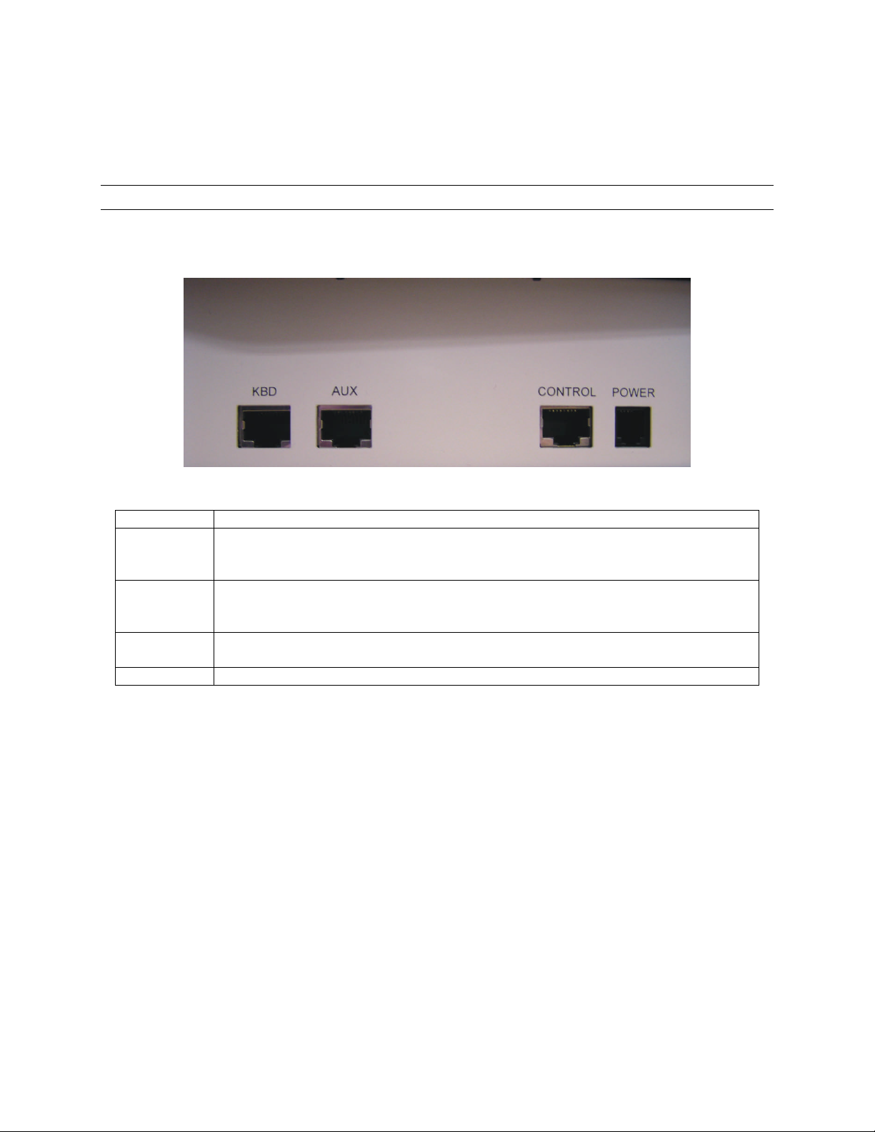
2.1 CONNECTIONS
All connections to and from the keyboard are made to the RJ type connectors located
on the rear panel of the unit.
Figure 1: HJZTP Rear Panel
Connector Function
KBD
(RS485)
AUX
(RS485)
CONTROL
(RS485)
POWER Connection to 12VDC 300mA power supply (supplied).
Master keyboard – To connect to a slave keyboard.
Slave keyboard – To connect to a higher number slave keyboard.
VCL dome data input to master keyboard or last slave keyboard.
Master keyboard – To connect either to a DVR or a multiplexer.
slave keyboard – To connect either to the master keyboard, or a lower number
slave keyboard.
RS485 telemetry output – for connection to PTZs (Honeywell domes) or RS485
distribution box.
Rev. 1.01 3 900.0570
8-Sept-05
Page 14

2.2 SUPPLIED CABLES
2.2.1 Eight-Way RJ45 Connector to Eight-Way RJ45 Connector
This cable is used to connect a slave keyboard to a master keyboard, a slave keyboard
to a slave keyboard, and a master keyboard to a multiplexer.
2.2.2 Eight-Way RJ45 Connector to White/Orange Wire and Orange Wire
This cable is used to connect the master keyboard to the domes RS485 connection. The
orange/white wire is data +, and the orange wire is data -.
2.2.3 Eight-Way RJ45 Connector to Green Wire and Blue Wire
This cable is used to connect the master keyboard to the DVRs RS485 connection. The
green wire is data +, and the blue wire is data -.
This cable can also be used to input Orbiter / RapidDome RS485 data from a control
device to the master keyboard, or last slave keyboard. Again the green wire is data +,
and the blue wire is data -.
Rev. 1.01 4 900.0570
8-Sept-05
Page 15
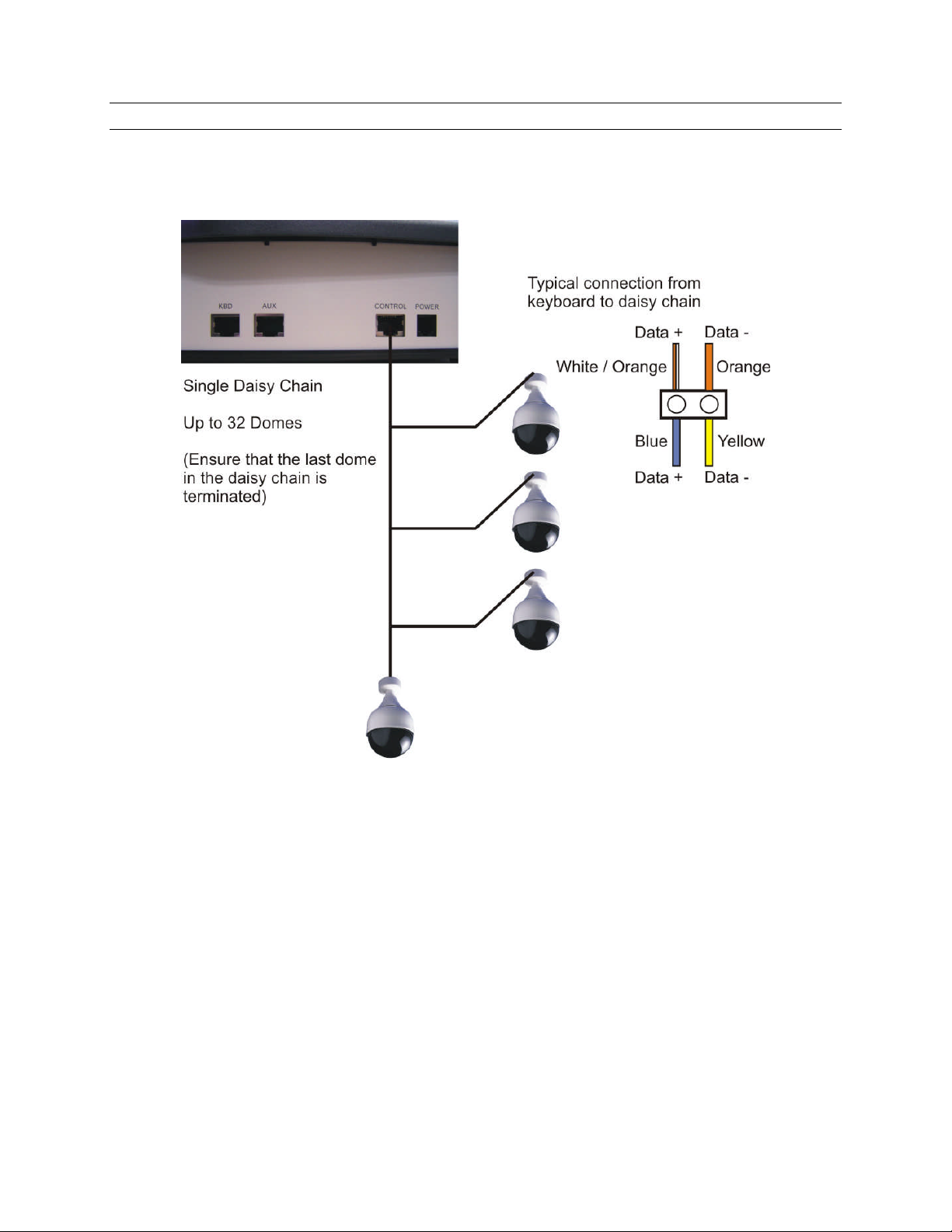
2.3 DOME CONNECTIONS
2.3.1 Daisy chain
Figure 4. DOME DAISY CHAIN CONFIGURATION
Rev. 1.01 5 900.0570
8-Sept-05
Page 16
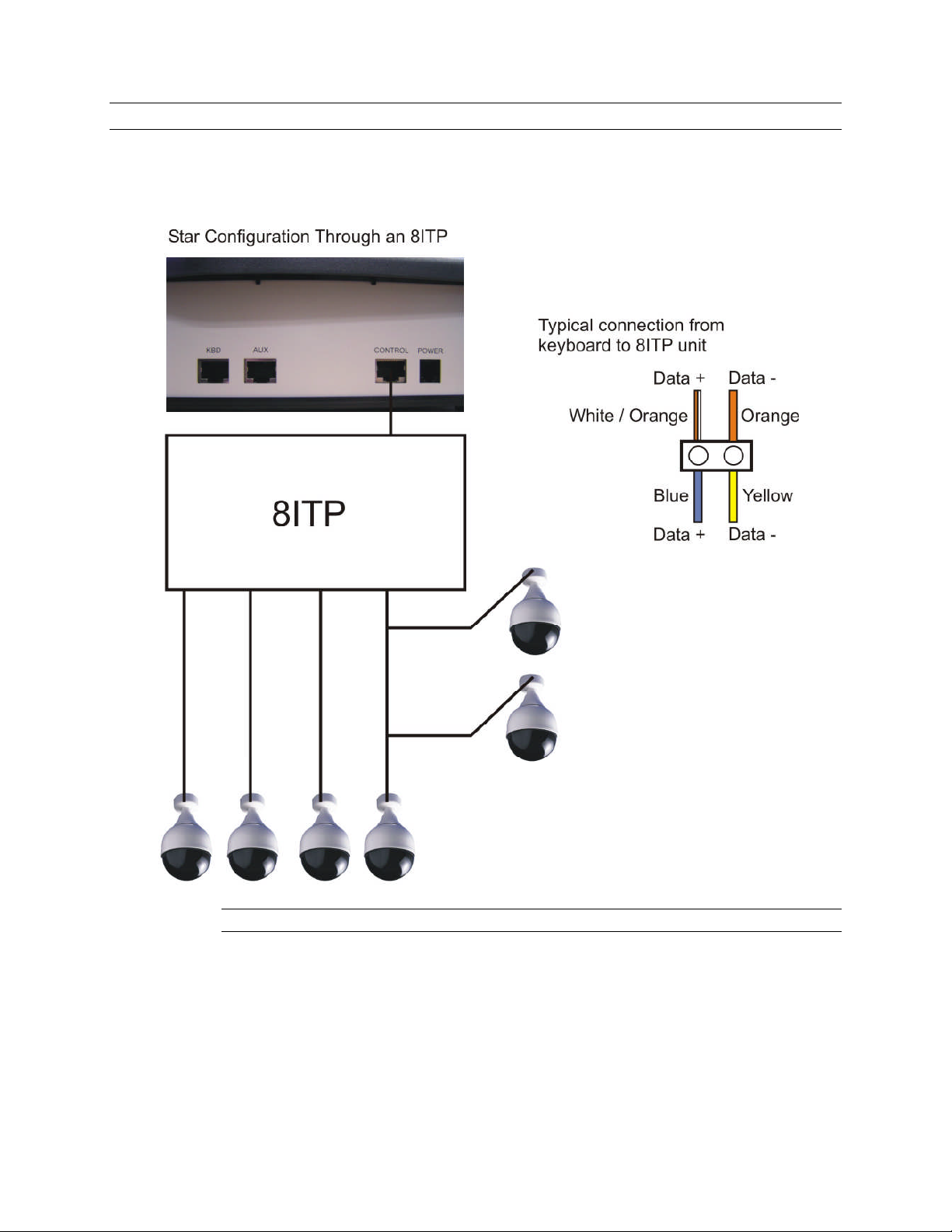
2.3 DOME CONNECTIONS, CONTINUED
2.3.2 Star Wiring Configuration
Note: Details on termination and dome installation are covered in the dome manual.
Figure 5. DOME STAR WIRING CONFIGURATION
Rev. 1.01 6 900.0570
8-Sept-05
Page 17
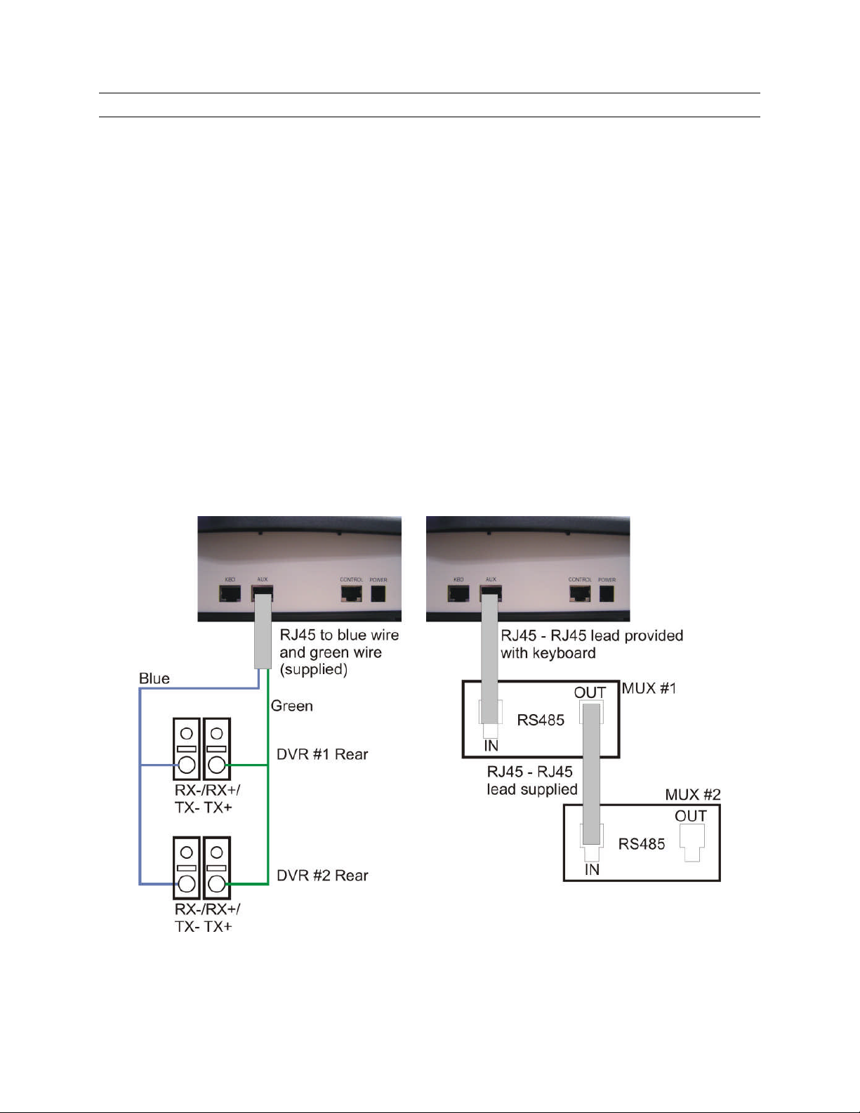
2.4 DVR AND MULTIPLEXER CONNECTION
2.4.1 DVR Setup
The DVR unit ID and RS485 port settings must be correctly set using the menus on the
DVR before it can be controlled using the HJZTP keyboard.
Baud Rate - 9600
Parity - None
Data – 8
Stop – 1
Usage - Remote control
Unit ID - 1 for DVR 1, 2 for DVR 2 etc.
2.4.2 Multiplexer Setup
The multiplexer address and communication settings must be correctly set using the
menus on the multiplexer before it can be controlled using the HJZTP keyboard.
Network Type - RS485
Baud Rate - 9600
Protocol - A
Unit Address - 001 for multiplexer 1, 002 for multiplexer 2 etc
Figure 6. CONNECTION TO MULTIPLEXERS AND DVRS
Rev. 1.01 7 900.0570
8-Sept-05
Page 18
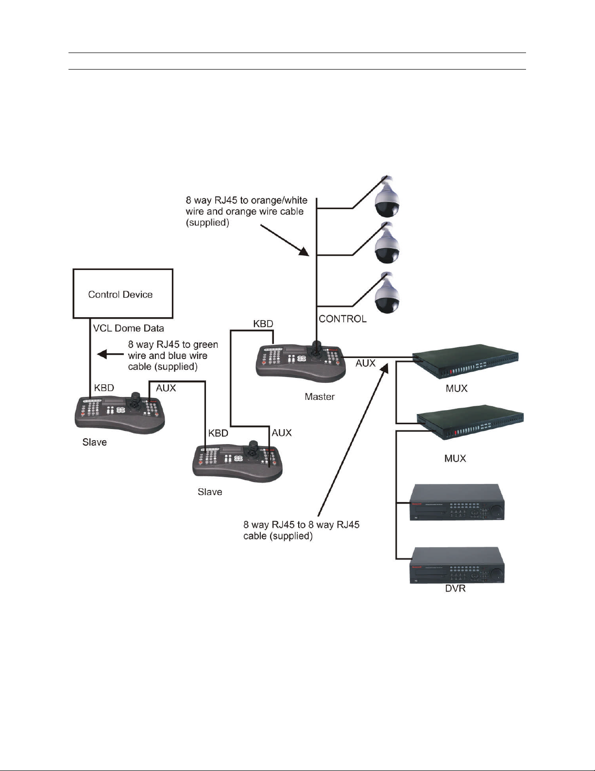
2.5 KEYBOARD CASCADING
It is possible to cascade up to three slave keyboards off a master keyboard that is
connected to the multiplexer / DVR and dome RS485 line. All keyboards in the cascade
can communicate with any DVR, multiplexer, or dome connected to the master.
2.5.1 Master/Slave Connection
A system of cascaded keyboards is connected as shown below.
Figure 7. SAMPLE SYSTEM OF CASCADED KEYBOARDS.
In the above system two slave keyboards are connected to a master keyboard. The
system also has two multiplexers, and two DVRs connected. And VCL (Orbiter / Rapid )
dome data is being input into the system from a control device.
Rev. 1.01 8 900.0570
8-Sept-05
Page 19
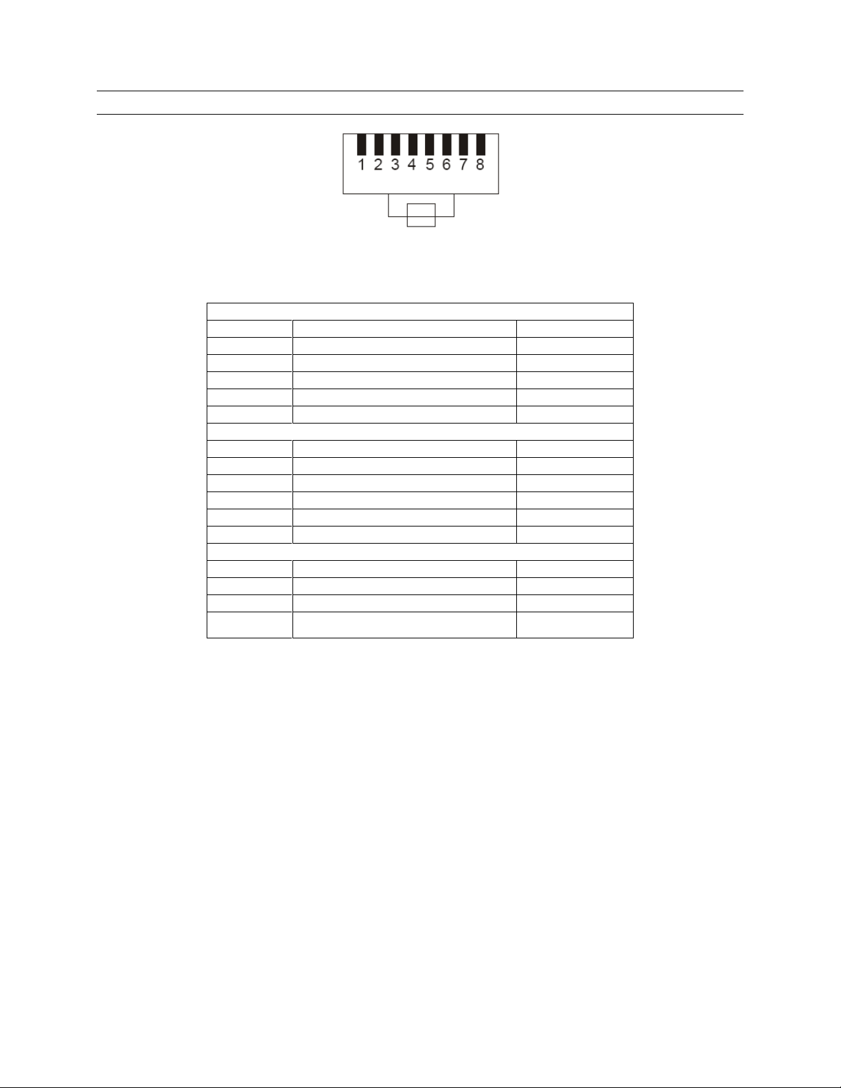
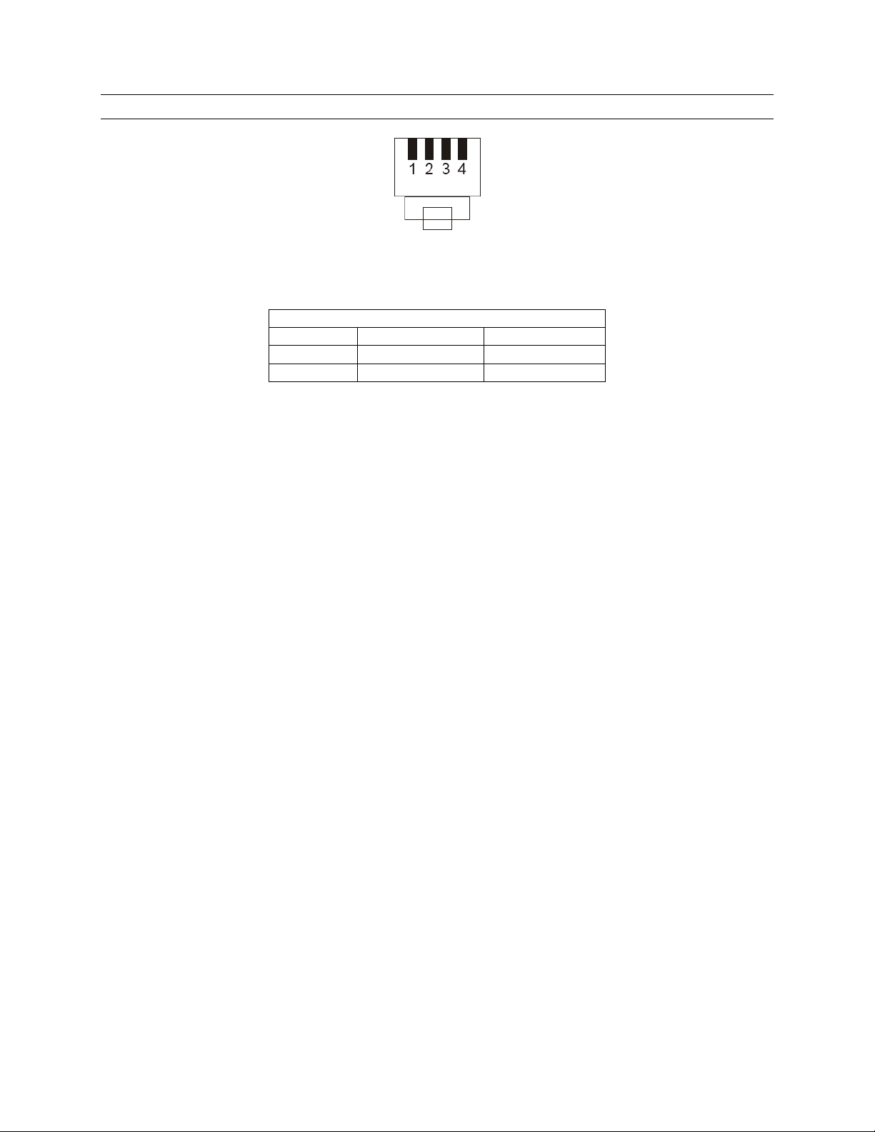
2.6 CONNECTOR PIN ASSIGNMENTS
Viewed from wiring input side of plug
Figure 2. KBD/AUX/CONTROL CONNECTORS
Pin Signal Usual colour
1 To slave D+ White / Orange
2 To slave D- Orange
4 From slave or VCL data in D- Blue
5 GND White / Blue
6 From slave or VCL data in D+ Green
Pin Signal Usual colour
1 From master D+ White / Orange
2 From master D- Orange
4 To DVR or master D- Blue
5 GND White / Blue
6 To DVR or master D+ Green
CONTROL
Pin Signal Usual colour
1 To / from dome D+ White / Orange
2 To / from dome D- Orange
3 GND White / Green
KBD
AUX
Rev. 1.01 9 900.0570
8-Sept-05
Page 20
2.6 CONNECTOR PIN ASSIGNMENTS, CONTINUED
Viewed from wiring input side of plug
Figure 3. POWER CONNECTOR
POWER
Pin Signal Usual colour
1 GND Green
4 +12 VOLTS Red
Rev. 1.01 10 900.0570
8-Sept-05
Page 21

3.1 KEYBOARD LOCK
If the keyboard is locked, the ‘lock’ key will be illuminated, and the LCD display will
display:
The keyboard can be unlocked with different user control levels. Pressing and holding
the ‘lock’ key and entering the four digit unlock code will unlock the keyboard.
XXXX is the user level 1 unlock code. (Code not shown)
3434 is the user level 2 unlock code.
User level 1 allows all the features of the keyboard to be controlled by the user. When
the keyboard is unlocked with user level 1 control, ‘U1’ will be displayed on the LCD.
SECTION 3:
SETUP
L O C K E D
User level 2 allows limited control of the keyboard’s features by the user. When the
keyboard is unlocked with user level 2 control, ‘U2’ will be displayed on the LCD.
Use the same key sequences to lock the keyboard (‘lock‘ + 3434 or ‘lock’ + XXXX)
where XXXX is the user level 1 password.
If the keyboard is in user level 1 mode, and the ‘lock‘ 3434 key sequence is entered,
then the keyboard will be put into user level 2 mode.
Rev. 1.01 11 900.0570
8-Sept-05
Page 22

3.2 LCD DISPLAY
The LCD display shows information about the current operating state of the keyboard. If
the keyboard is operating in DVR control mode, then the display will be as shown below:
C A M E R A n n n D V R n n
P R E S E T n n n U n
‘CAMERA nnn’ is the camera which the keyboard is currently sending telemetry control
to. This camera may not always be a camera which is being displayed, as it is possible
to change the controlled camera without changing the displayed camera when in PTZ
mode (PTZ LED illuminated). Also if the DVR or multiplexer are showing a camera
sequence, then their displayed camera may be different to the controlled camera.
‘DVR nn’ is the DVR which is being controlled.
‘PRESET nnn’ will be displayed if the controlled camera is at preset number ‘nnn’.
Note: ‘PRESET nnn’ is not displayed when the keyboard is set to send Diamond
protocol.
‘Un’ is the user control level. ‘U1’ means the keyboard is in user level 1 control mode,
‘U2’, means the keyboard is in user level 2 control mode.
If the keyboard is operating in multiplexer control mode then the display will be as
shown below:
C A M E R A n n n M U X n n
P R E S E T n n n S P O T n U n
‘MUX nn’ is the multiplexer which is being controlled.
‘SPOT n’ will be displayed when the keyboard is controlling the multiplexers spot
monitor number n. When the keyboard is controlling the multiplexers main monitor
‘MAIN’ will be displayed instead.
Rev. 1.01 12 900.0570
8-Sept-05
Page 23

3.3 SYSTEM SETUP
Before using the HJZTP keyboard it must be set-up to meet the systems requirements.
There are three aspects of the keyboards set-up which need to be set. These are
keyboard type, DVR / multiplexer / camera connection, dome protocol.
Pressing and holding the ‘lock’ key and entering XXXX (code not shown) on the
numeric keypad, will display the keyboard setup menu, as shown below:
A U X = S E T L O C K = E N D
K E Y B R D D V R / M U X P R T C L
‘KEYBRD’ will be flashing. Use the joystick left and right or the ‘F3’ (‘◄’) and ‘F4’ (‘►’)
keys (or ‘camera’ and ‘preset’ buttons), to select the required option. Pressing ‘aux’ will
then enter the required menu.
3.3.1 Keyboard Type
The keyboard can be set as a master keyboard or one of 3 slave keyboards. The default
setting is as a master keyboard.
If there is only one keyboard in the system or the keyboard is to be the one which is
connected to the domes and DVRs / multiplexers, then the keyboard must be set as a
master keyboard. Other keyboards in the system must be set as slaves. Up to three
slave keyboards can be connected to the master keyboard, each slave keyboard must
have a different slave keyboard number.
To set the keyboard type, select ‘KEYBRD’ in the keyboard setup menu. The following
menu will be displayed:
A U X = S E T L O C K = E N D
M S T R S L V 1 S L V 2 S L V 3
If the keyboard has not been set-up before ‘MSTR’ will be flashing, otherwise the
keyboards current setting will be flashing. Use the joystick left and right or the ‘F3’ (‘’)
and ‘F4’ (‘’) keys (or ‘camera’ and ‘preset’ keys) to select the required option, then
press ‘aux’. The keyboard type selected will be displayed for 1 second to confirm the
selection, as shown below (n is the Slave number):
S L A V E n K E Y B O A R D
Or:
M A S T E R K E Y B O A R D
Once the required keyboard type has been selected, press ‘lock’ to exit the menu.
Rev. 1.01 13 900.0570
8-Sept-05
Page 24

3.3.2 DVR/Multiplexer/Camera Connection
Note: The DVR/multiplexer/camera connection can only be set from the master
keyboard. The DVR/MUX menu can be viewed on a slave keyboard, but ‘AUX = SET’
will not be displayed, and no editing will be allowed. To ensure slave keyboards have the
correct DVR/multiplexer/camera connection configuration, they must be set as slave
keyboards, and connected to the master keyboard before editing the configuration on
the master keyboard. Alternately, entering and exiting the DVR/MUX menu on the master
keyboard, or powering up the master keyboard, will resend the configuration to the slave
keyboards.
By default the keyboard it is set to control eight 16-way DVRs, and eight 16-way
multiplexers. With cameras 1 to 16 connected to DVR 1 and multiplexer 1, cameras 17 to
32 connected to DVR 2 and multiplexer 2, etc., up to cameras 113 to 128 connected to
DVR 8 and multiplexer 8.
The keyboard can control 1, 4, 9 and 16-way DVRs and/or 4, 9, 16-way multiplexers
To set the DVR/multiplexer/camera connection, select ‘DVR / MUX’ in the keyboard
setup menu. The following menu will be displayed:
A U X = S E T L O C K = E N D
C A M 1 D V R 1 M U X 1
The menu shows that camera 1 is connected to DVR 1 and Multiplexer 1. The number ‘1’
next to ‘DVR’ will be flashing indicating that this number will be edited by pressing the
‘aux’ key.
Use the joystick up and down or the ‘F1’ (‘’) and ’F2’ (‘’) keys, to scroll through all
128 cameras.
Use the joystick left and right or the ‘F3’ (‘’) and ‘F4’ (‘’) keys (or ‘camera’ and
‘preset’ keys) to select the DVR or MUX number.
Pressing the ‘aux’ key will cycle through all legal settings of the selected DVR or
multiplexer number. ‘NO’, indicates no DVR or no multiplexer is connected to the
camera.
The menu only allows cameras be assigned to DVRs in blocks of 1, 4, 9 or 16, or to
Multiplexers in blocks of 4, 9 or 16, to correspond with 1, 4, 9 or 16-way
DVRs/Multiplexers. If ‘AUX = SET’ is not displayed, then there are no legal alternatives to
the number already displayed, and so the number cannot be edited.
Rev. 1.01 14 900.0570
8-Sept-05
Page 25

3.3.2 DVR/Multiplexer/Camera Connection, Continued
Example: If a system has 40 cameras with:
DVR 1, a 4-way DVR connected to cameras 1 through 4 inclusive
DVR 2, a 4-way DVR connected to cameras 5 through 8 inclusive
DVR 3, a 16-way DVR connected to cameras 9 through 24 inclusive
DVR 4, a 9-way DVR connected to cameras 25 through 33 inclusive
DVR 5, a 4-way DVR connected to cameras 35 through 38 inclusive
DVR 6, a 1-way DVR connected to camera 39
Cameras 34 and 40 not connected to a DVR
Multiplexer 1, a 16-way multiplexer connected to cameras 1 through 16 inclusive
Multiplexer 2, a 16-way multiplexer connected to cameras 17 through 32 inclusive
Multiplexer 3, a 4-way multiplexer connected to cameras 33 through 36 inclusive
Cameras 37 through 40 inclusive not connected to a multiplexer.
Then this system would be shown as in the table below:
CAM 1 DVR 1 MUX 1
CAM 2 DVR 1 MUX 1
CAM 3 DVR 1 MUX 1
CAM 4 DVR 1 MUX 1
CAM 5 DVR 2 MUX 1
CAM 6 DVR 2 MUX 1
CAM 7 DVR 2 MUX 1
CAM 8 DVR 2 MUX 1
CAM 9 DVR 3 MUX 1
CAM 10 DVR 3 MUX 1
CAM 11 DVR 3 MUX 1
CAM 12 DVR 3 MUX 1
CAM 13 DVR 3 MUX 1
CAM 14 DVR 3 MUX 1
CAM 15 DVR 3 MUX 1
CAM 16 DVR 3 MUX 1
CAM 17 DVR 3 MUX 2
CAM 18 DVR 3 MUX 2
CAM 19 DVR 3 MUX 2
CAM 20 DVR 3 MUX 2
CAM 21 DVR 3 MUX 2
CAM 22 DVR 3 MUX 2
CAM 23 DVR 3 MUX 2
CAM 24 DVR 3 MUX 2
CAM 25 DVR 4 MUX 2
CAM 26 DVR 4 MUX 2
CAM 27 DVR 4 MUX 2
CAM 28 DVR 4 MUX 2
CAM 29 DVR 4 MUX 2
CAM 30 DVR 4 MUX 2
CAM 31 DVR 4 MUX 2
CAM 32 DVR 4 MUX 2
CAM 33 DVR 4 MUX 3
CAM 34 DVR NO MUX 3 No DVR
CAM 35 DVR 5 MUX 3
CAM 36 DVR 5 MUX 3
CAM 37 DVR 5 MUX NO No multiplexer
CAM 38 DVR 5 MUX NO
CAM 39 DVR 6 MUX NO 1 way DVR (DVR 6) No multiplexer
CAM 40 DVR NO MUX NO No DVR No multiplexer
4 way DVR (DVR 1)
4 way DVR (DVR 2)
16 way DVR (DVR 3)
9 way DVR (DVR 4)
4 way DVR (DVR 5)
16 way multiplexer
(MUX 1)
16 way multiplexer
(MUX 2)
4 way multiplexer
(MUX 3)
No multiplexer
Only one row of this table is displayed at a time on the LCD menu.
Once the DVR/multiplexer/camera configuration has been set, press ‘lock’ to exit the
menu.
Rev. 1.01 15 900.0570
8-Sept-05
Page 26

3.3.3 Dome (PTZ) Protocol
The keyboard can be set up to control RapidDome/Orbiter type domes using Honeywell
VCL protocol or KD6/HD6 type domes using Honeywell Diamond protocol.
Note: The protocol can only be set from the master keyboard. The protocol menu can
be viewed on a slave keyboard, but ‘AUX = SET’ will not be displayed, and no selection
will be allowed. To ensure slave keyboards have the correct protocol setting, they must
be set as slave keyboards, and connected to the master keyboard, before editing the
protocol on the master keyboard. Alternately entering and exiting the protocol menu on
the master keyboard, or powering up the master keyboard will re-send the protocol
setting to the slave keyboards.
To set the dome protocol, select ‘PRTCL’ in the keyboard setup menu. The following
menu will be displayed:
A U X = S E T L O C K = E N D
P R O T O C O L - V C L
Press ‘aux’ to toggle between ‘VCL’ and ‘DIAMOND’. Once the required protocol has
been selected, press ‘lock’ to exit the menu.
Rev. 1.01 16 900.0570
8-Sept-05
Page 27

SECTION 4:
DVR CONTROL FUNCTIONS
4.1 DVR MODE
Press the ‘mode’ key to toggle between multiplexer and DVR mode.
4.2 NUMBER ENTRY (FOR ENTERING PASSWORDS)
To send numbers to the DVR, press and hold the ‘Fn’ key, then press the number keys.
Alternately, press and hold the ‘F6’ (‘menu’), ‘rw’, ‘ff’, ‘play’, ‘rec’, ‘search’ or ‘alarm’
keys, to send numbers to there password screens.
4.3 DVR MENUS
Press and hold the ‘F6’ (‘menu’) key to bring up the password screen.
Whilst holding the ‘F6’ (‘menu’) key, press the number keys to enter numbers on the
password screen.
Press the ‘F5’ (‘enter’) key to enter the password and gain access to the DVR set-up
menus.
Navigation around these menus is achieved by using the function keys as indicated in
the following table:
Key Function
F1 (▲) Up
F2 (▼) Down
F3 (◄) Left
F4 (►) Right
F5 (enter) Enter
F6 (menu) Menu
Press the ‘F1’ (‘▲’), ’F2’ (‘▼’), ‘F3’ (‘◄’) or ‘F4’ (‘►’) keys to move around the menu
pages.
Press the ‘F5’ (‘enter’) key to select an option within the menus.
Press the ‘F6’ (‘menu’) key to exit the current menu. (If the user presses ‘F6’ when in
the‘set-up screen’, the DVR exits the menus and returns to normal operation.)
Note: Menus are not accessible to users logged in as user level 2 (U2 displayed on the
LCD).
Rev. 1.01 17 900.0570
8-Sept-05
Page 28

4.4 PICTURE CONTROL
The following table indicates the keys used for picture control:
Press the ‘display’ key to select the next display setting (in the cycle of ‘4x4’, ‘3x3’, ‘2x2’
and ‘PIP’).
Use the F3 (◄) and F4 (►) keys to cycle through the other cameras when displaying 2x2
and 3x3 displays.
The screen layout of the multi-camera displays can be set by pressing the ‘F5’ (‘enter’)
key, then ‘F1’ (‘’), ’F2’ (‘’), ‘F3’ (‘’) or ‘F4’ (‘’) keys to select an active cameo
(highlight box displayed). Then press one or two of the number keys (to enter a legal
camera number) followed by the ‘camera’ key to select that number camera to be
displayed in that cameo.
Press the ‘sequence’ key to put the DVR output into a sequence (the sequence depends
on the current display mode and set-up). If the key is pressed again, the sequence stops
(displaying the current step in the sequence).
Key Function
display Display
sequence Sequence
freeze Freeze
Press the ‘freeze’ key to freeze the current display. Press the key again to return to the
‘live’ picture(s).
4.5 CAMERA SELECTION
Press one or two of the number keys (to enter a legal camera number) followed by the
‘camera’ key to select that number camera for full-screen display on the DVR output.
This also selects the associated DVR.
Press the ‘camera’ key by itself to increment the camera selection by one.
Note: Both of the above selection processes also make the displayed camera the
controlled camera as shown on the keyboards LCD display. The controlled camera can
be changed independently of the DVRs displayed camera(s) by putting the keyboard in
PTZ mode. To enable/disable PTZ mode, press and hold the ‘Fn’ key , then press the
‘mode’ key. When in PTZ mode the PTZ LED will be on
4.6 DVR SELECTION
Pressing a number followed by the ‘Fn’ key selects a DVR to control. This also selects
the last camera controlled on that DVR (or the first camera input on that DVR if it has not
been selected previously).
Rev. 1.01 18 900.0570
8-Sept-05
Page 29

4.7 RECORDING AND PLAYBACK
The following table indicates the keys used for recording and playback, only the counter
function is available to users logged in as user level 2 (U2 displayed on the LCD):
Key Function User Level Required
search Search U1
play Play/Pause U1
rw Rewind U1
ff Fast Forward U1
stop Stop U1
rec Record U1
counter Counter U1 or U2
Fn + Joystick Right/Left Shuttle Forwards/Backwards U1
Fn + Joystick Up/Down Jog Forwards/Backwards U1
Fn + rec Panic U1
Note: If user password is enabled on the DVR, then pressing the ‘search’, ‘play’, ‘rw’, ‘ff,
or ‘rec’, key will cause a user password screen to be displayed. If a user password is
required, keep the key (‘search’, ‘play’, ‘rw’, ‘ff, or ‘rec’) pressed whilst entering the
password. Alternately, press and hold the ‘Fn’ key, then press the number keys
Press the ‘search’ key to bring up the ‘search’ menu. Press the key again to exit the
‘search’ menu.
Press the ‘counter’ key to toggle the DVR display between displaying or not displaying
the remaining storage capacity.
To increase the speed of rewind or fast forward, press the ‘rew’ or ‘ff’ key up to four
times to reach the maximum speed. Alternately, if the DVR is in ‘playback’ mode, press
and hold the ‘Fn’ key and move the joystick right to play the video forwards or left to
play the video backwards. The more the joystick is moved the faster the video is played.
If the joystick is returned to the centre position or the ‘Fn’ key is released, the shuttle is
returned to the centre position (and the playback is paused).
If the DVR is paused in ‘playback’ mode, press and hold the ‘Fn’ key and move the
joystick up to play the video forwards image-by-image or down to play the video
backwards image-by-image. If the joystick is held up or down, the video is moved on to
the next image (either forwards or backwards) every 0.5 seconds.
Rev. 1.01 19 900.0570
8-Sept-05
Page 30

4.8 ALARM FUNCTION
If an alarm is active, press the ‘alarm’ key to reset the DVR’s outputs (including internal
buzzer).
If the DVR is in the live monitoring mode (and no alarm is active), press the ‘alarm’ key to
display the event log. (Once in the event log, it is navigated in the same way as the
menus as detailed in ‘4.3 DVR Menus’).
Note: If user password is enabled on the DVR, then pressing the ‘alarm’ key will cause a
user password screen to be displayed. If a user password is required, keep ‘alarm’
pressed whilst entering the password. Alternately, press and hold the ‘Fn’ key, then
press the number keys.
4.9 SPOT FUNCTION
To display a camera on the spot monitor, first press the ‘monitor’ key, then press one or
two of the number keys (to enter a legal camera number) followed by the ‘camera’ key to
select that number camera for display on the spot monitor.
Press ‘monitor’ then ‘sequence’ to put the spot monitor into a camera sequence.
Rev. 1.01 20 900.0570
8-Sept-05
Page 31

MULTIPLEXER CONTROL FUNCTIONS
5.1 MULTIPLEXER MODE
Press the ‘mode’ key to toggle between multiplexer and DVR mode.
5.2 MENUS
Navigation around menus is achieved by using the function keys as indicated in the
following table
SECTION 5:
Key Function
F1 (▲) Up
F2 (▼) Down
F3 (◄) Left
F4 (►) Right
F5 (enter) Set
F6 (menu) Esc
Note: Menus are not accessible to users logged in as user level 2 (U2 displayed on the
LCD).
5.2.1 Setup (Top) Menu
To enter the multiplexer set-up menu press the ‘F1’ (‘▲’) key twice to display:
LIVE Playback Preview Setup Cancel
Use the ‘F3’ (‘◄’) or ‘F4’ (‘►’) keys to select ‘Setup’, then press ‘F5’ (‘enter’).
Press the ‘F1’ (‘▲’), ’F2’ (‘▼’), ‘F3’ (‘◄’) or ‘F4’ (‘►’) keys to move around the menu
pages.
Press the ‘F5’ (‘enter’) key to select an option within the menus.
To exit the menus select ‘Exit’, and then press the ‘F5’ (‘enter’) key.
Rev. 1.01 21 900.0570
8-Sept-05
Page 32

5.2.2 Bottom Menu
To enter the multiplexer bottom menu press the ’F2’ (‘▼’), key twice to display:
Full 2x2 3x3 4x4 PIP
User Def1 User Def2 User Def3 User Def4 Cancel
Use the ‘F1’ (‘▲’), ’F2’ (‘▼’), ‘F3’ (‘◄’) or ‘F4’ (‘►’) keys to select the required option,
then press ‘F5’ (‘enter’).
5.2.3 Pop Up Menu
Pressing the ‘F1’ (‘▲’), ’F2’ (‘▼’), ‘F3’ (‘◄’) or ‘F4’ (‘►’) keys in live screen mode will
select a camera image (red border around image). Once the required image has been
selected, press the ‘F5’ (‘enter’) to display:
Live Cam Change…
Zoom…
Full
Priority On
Histogram On..
Panic Record On
Freeze On
Sequence
Utilities
Cancel
Use the ‘F1’ (‘▲’), ’F2’ (‘▼’) keys to select the required option, then press ‘F5’ (‘enter’).
5.3 PICTURE CONTROL
The following table indicates the keys used for picture control:
display Display
sequence Sequence
freeze Freeze
play Toggle VCR input
search Digital Zoom
Press the ‘display’ key to select the next display setting (in the cycle of ‘4x4’, ‘3x3’, ‘2x2’
and ‘PIP’ for a 16 way multiplexer, ‘3x3’, ‘2x2’ and ‘PIP’ for a 9 way multiplexer or ‘2x2’
and ‘PIP’ for a 4 way multiplexer).
Press and hold the ‘Fn’ key, then press the ‘display’ key to cycle through the other
cameras when displaying 2x2 and 3x3 displays.
Press the ‘sequence’ key to put the multiplexer output into a sequence (the sequence
depends on the current display mode and set-up). If the key is pressed again, the
sequence stops (displaying the current step in the sequence).
Press the ‘freeze’ key to freeze the current display. Press the key again to return to the
‘live’ picture(s).
Key Function
Rev. 1.01 22 900.0570
8-Sept-05
Page 33

5.3 PICTURE CONTROL, CONTINUED
Press the ‘play’ key to select the VCR input for display. (Pressing the key again will
return the multiplexer to ‘live’ picture(s).
Press the ‘search’ key to select the ‘zoom’ mode (see below). Once in ‘zoom’ mode,
press the ‘search’ key again to exit ‘zoom’ mode.
Note: Zoom is not accessible to users logged in as user level 2 (U2 displayed on the
LCD
To use the zoom feature (once in ‘zoom’ mode), press the following keys to move the
zoomed area.
Key Function
F1 (▲) Up
F2 (▼) Down
F3 (◄) Left
F4 (►) Right
F5 (enter) Zoom In
F6 (menu) Zoom Out
Search Exit
5.4 AUXILIARY MONITOR SELECTION
Pressing a number (1 to 4) followed by the ‘monitor’ key selects that number auxiliary
monitor for control by the keyboard (the spot monitor number will be displayed on the
LCD).
Pressing the ‘monitor’ key without first entering a number returns the keyboard control
back to the main monitor (MAIN displayed on the LCD).
Note: Pressing ‘F6’ (‘menu’), ‘display’, ‘alarm’ and ‘play’ will also put the multiplexer
back to main monitor control
5.5 CAMERA SELECTION
Camera selection will be performed on the monitor currently under control (Main or Spot
1 to 4).
Pressing a number followed by the ‘camera’ key selects a camera to display. This also
selects the associated multiplexer.
Pressing the ‘camera’ key by itself increments the camera selection.
Note: that both of the above selection processes also make the displayed camera the
controlled camera as shown on the keyboards LCD display. The controlled camera can
be changed independently of the multiplexer display camera by putting the keyboard in
PTZ mode. To enable/disable PTZ mode, press and hold the ‘Fn’ key, then press the
‘mode’ key. When in PTZ mode the PTZ LED will be on.
Rev. 1.01 23 900.0570
8-Sept-05
Page 34

5.6 MULTIPLEXER SELECTION
Pressing a number followed by the ‘Fn’ key selects a multiplexer to control. This also
selects the last camera controlled on that multiplexer (or the first camera input on that
multiplexer if it has not been selected previously).
Rev. 1.01 24 900.0570
8-Sept-05
Page 35

SECTION 6:
PTZ CONTROL FUNCTIONS WHEN USING HONEYWELL VCL
(RAPIDDOME/ORBITER DOME) PROTOCOL
6.1 PTZ CAMERA SELECTION CONTROL
The PTZ cameras can be controlled while the keyboard is in any mode (DVR,
Multiplexer, or PTZ). The keyboard sends out standard telemetry to a PTZ or other
receiver connected via RS485.
Before a PTZ can be controlled it must first be selected by pressing one or two of the
number keys (to enter a legal camera number) followed by the ‘camera’ key. The
camera number that is displayed on the LCD is the camera that is being controlled.
6.2 PTZ MODE
PTZ mode changes the way the keyboard selects domes. To toggle between PTZ mode
ON and OFF, press and hold the ‘Fn’ key, then press the ‘mode’ key.
PTZ Mode OFF (PTZ LED OFF) Selecting a camera for control will also cause a full
PTZ Mode ON (PTZ LED ON) Enables cameras to be selected for control without
6.3 PAN AND TILT
Very precise control of pan and tilt can be achieved using the joystick. The speed of pan
and tilt is relative to the amount of movement applied to the joystick.
6.4 TURN 180°
This function allows the PTZ to view a person who is walking underneath the camera.
Press the ‘auto 180°’ key to pan the camera 180°.
The camera will pan 180° at the maximum speed. (Up to 400° per second.)
screen picture from that camera to be displayed
on the DVR (in DVR mode) or Multiplexer (in MUX
mode).
changing what is displayed on the monitors.
Rev. 1.01 25 900.0570
8-Sept-05
Page 36

HONEYWELL VCL PROTOCOL, CONTINUED
6.5 ZOOM
Rotate the top of the joystick clockwise to zoom in.
Rotate the top of the joystick counter-clockwise to zoom out.
6.6 FOCUS AND IRIS
Press the auto key above the focus control keys to toggle the camera in and out of ‘autofocus’ mode, if the feature is available on the selected camera/receiver.
Press the ‘+’ (FAR) or ‘-’ (NEAR) keys to manually focus the camera. (The camera
automatically changes to ‘manual focus’ mode if one of these two keys is pressed.)
Press the auto key above the iris control key to toggle the camera in and out of ‘auto-iris’
mode, if the feature is available on the selected camera / receiver. Press the ‘+’ (OPEN)
or ‘-’ (CLOSE) keys to manually alter the camera iris. (The camera automatically changes
to ‘manual iris’ mode if one of these two keys are pressed.)
6.7 WASH, WIPE AND AUXILIARY FUNCTIONS
If the receiver being controlled has WASH and WIPE functions, they are controlled as
follows:
FOR WIPE.
Press the ‘wipe’ key to activate the wiper.
Press the ‘wipe’ key again to turn off the wiper.
FOR WASH.
Press and hold the ‘wash’ key to activate the washer.
Release the ‘wash’ key to turn off the washer.
If the receiver has a separate momentary function (auxiliary), it is controlled as follows:
Press the ‘0’ key, then press and hold the ‘aux’ key to activate the auxiliary function.
Release the ‘aux’ key to turn off the auxiliary function.
Note: The ‘aux’ key illumination is not altered by this operation as it is used to monitor
‘Change Over’ RapidDome/Orbiter domes.
Rev. 1.01 26 900.0570
8-Sept-05
Page 37

HONEYWELL VCL PROTOCOL, CONTINUED
6.8 MANUAL CHANGE OVER (CHANGE OVER RAPIDDOME/ORBITER DOMES ONLY)
The operator can force the camera to change from MONO to COLOUR or COLOUR to
MONO by pressing the ‘aux’ key. The camera automatically changes back dependant
on the level of illumination.
If the camera is in the mode selected by the operator (and is different to the mode that
the camera would have automatically selected), the ‘aux’ key is illuminated.
If the camera is in the mode that the camera has automatically selected, the ‘aux’ key is
not illuminated.
6.9 PRESETS AND TOURS
6.9.1 To Define a Preset
Up to 128 presets can be defined. Presets are numbered 0 - 127.
For example, to define Preset 1.
1. Move the selected dome to view the desired preset position, using the joystick,
zoom, focus and iris keys.
2. Press and hold the ‘preset’ key.
3. Press ‘1’.
4. Release the ‘preset’ key.
The current position of the dome has now been defined as Preset 1.
6.9.2 To Seek a Preset
Note: A preset seek will only occur if the preset has previously been defined.
For Example, to seek Preset 1.
1. Press ‘1’.
2. Press the ‘preset’ key.
The camera will now move at the maximum speed to the previously defined Preset
1.
The user may also select presets 1 - 4 by single key presses using the keys labelled
‘preset’ ‘1’ to ‘4’.
Rev. 1.01 27 900.0570
8-Sept-05
Page 38

HONEYWELL VCL PROTOCOL, CONTINUED
6.9.3 To Start a Tour of Presets
A RapidDome/Orbiter can store four different preset tours. After programming the tours,
as detailed in the next sections, they may be recalled in the following way.
1. Press the number key that corresponds to the tour number, either ‘1’, ‘2’, ‘3’, or ‘4’.
2. Press the ‘autopan’ key.
6.9.4 To Define a Simple Tour
For example to define a tour for three preset positions in memory as ‘Tour 1’.
Note: First, define the three preset positions, as detailed in section 6.1.7.1 above.
1. Press ‘1’, then press and hold the ‘autopan’ key. (This will define ‘Tour 1’.)
2. Press ‘1’, then press the ‘preset’ key. (This selects the first preset in ‘Tour 1’.)
3. Press ‘2’, then press the ‘preset’ key. (This selects the second preset in ‘Tour 1’.)
3. Press ‘3’, then press the ‘preset’ key. (This selects the third preset in ‘Tour 1’.)
4. Release the ‘autopan’ key.
The tour is now set up. To operate ‘Tour 1’
5. Press ‘1’, then press the ‘autopan’ key.
The tour will now be set with a standard speed of 30°/sec and the dwell time at each
preset set to a standard 60 seconds.
6.9.5 To Vary the Standard Speed of a Tour
For example to define a tour (as set in 6.1.7.4, above.) in memory as ‘Tour 2’ with
different speeds between preset positions:
1. Press ‘2’, then press and hold the ‘autopan’ key. (This will define ‘Tour 2’.)
2. Press ‘1’, then press the ‘preset’ key. (This selects the first preset in ‘Tour 2’.)
3. Press ‘5’, then press ‘0’, then press the ‘180°’ key. (This defines 50°/sec to this preset
position.)
4. Press ‘2’, then press the ‘preset’ key. (This selects the second preset in ‘Tour 2’.)
5. Press ‘1’, then press ‘0’, then press ‘0’, then press the ‘180°’ key. (This defines 100°/
sec to this preset position.)
6. Press ‘3’, then press the ‘preset’ key. (This selects the third preset in ‘Tour 2’.)
Rev. 1.01 28 900.0570
8-Sept-05
Page 39

HONEYWELL VCL PROTOCOL, CONTINUED
6.9.5 To Vary the Standard Speed of a Tour, Continued
7. Press ‘2’, then press the ‘180°’ key. (This defines 2°/sec to this preset position.)
8. Release the ‘autopan’ key.
6.9.6 To Vary the Standard Speed of a Tour, Continued
The tour is now set up. To operate ‘Tour 2’:
Press ‘2’, then press the ‘autopan’ key.
Note: The range of speeds that can be selected goes from ‘1’ = 1°/sec up to ‘100’ =
100°/sec. To select the maximum seek speed, press ‘0’.
6.9.7 To Vary the Standard Speeds and Dwell Times of a Tour
For example to define a tour (as set in 6.1.7.4, above.) in memory as ‘Tour 3’ with
different dwell times between preset positions:
1. Press ‘3’, then press and hold the ‘autopan’ key. (This will define ‘Tour 3’.)
2. Press ‘1’, then press the ‘preset’ key. (This selects the first preset in ‘Tour 3’.)
3. Press ‘5’, then press ‘0’, then press the ‘180°’ key. (This defines 50°/sec to this preset
position.)
4. Press ‘1’, then press ‘0’, then press the ‘counter’ key. (This defines a 10 second
dwell time at this preset position.)
5. Press ‘2’, then press the ‘preset’ key. (This selects the second preset in ‘Tour 3’.)
6. Press ‘1’, then press ‘0’, then press ‘0’, then press the ‘180°’ key. (This defines
100°/sec to this preset position.)
7. Press ‘1’, then press ‘6’, then press the ‘counter’ key. (This defines a 16 second
dwell time at this preset position.)
8. Press ‘3’, then press the ‘preset’ key. (This selects the third preset in ‘Tour 3’.)
9. Press ‘2’, then press the ‘180°’ key. (This defines 2°/ sec to this preset position.)
10. Press ‘1’, then press ‘4’, then press the ‘counter’ key. (This defines a 14 second
dwell time at this preset position.)
11. Release the ‘autopan’ key.
Rev. 1.01 29 900.0570
8-Sept-05
Page 40

HONEYWELL VCL PROTOCOL, CONTINUED
6.9.7 To Vary the Standard Speeds and Dwell Times of a Tour, Continued
The tour is now set up. To operate ‘Tour 3’:
Press ‘3’, then press the ‘autopan’ key.
Note: The range of the dwell times that can be set varies from 1 to 254 seconds.
Entering a time of ‘0’ will select 1 second dwell time.
6.9.8 To Stop a Tour of Presets
Press the ‘autopan’ key. (This will turn off the tour.)
The tour will also stop if the telemetry buttons or the joystick are used to control the
dome.
6.9.9 To Restart a Tour of Presets
Press the ‘autopan’ key. (This will start the last tour that the dome was carrying out.)
6.10 ENHANCED FUNCTIONS
The keyboard can also access most of the advanced functions of the RapidDome
/Orbiter series of domes by using its LCD menus. Joystick up, down, left and right or the
‘F1’ (‘▲’), ’F2’ (‘▼’), ‘F3’ (‘◄’) or ‘F4’ (‘►’) keys, are used to select options within the
menus. The ‘camera’ and ‘preset’ keys can also be used to move to the left or right
option.
The LCD menus adjust the setup of the dome that is currently being controlled (camera
number displayed on LCD display, before entering the menu).
Note: Menus are not accessible to users logged in as user level 2 (U2 displayed on the
LCD).
To enter the camera setup menu, press and hold ‘lock’, then press ‘F6’ (‘menu’). The
camera setup menu will be shown as below:
A U X = S E T L O C K = E N D
H O M E P R I V A C Y R E S E T
‘HOME’ will be flashing to indicate that ‘HOME’ is the currently selected option.
Use joystick down or ’F2’ (‘▼’), to select the other options as shown below:
A U X = S E T L O C K = E N D
Z O O M I R / L A M P A U T O 1 8 0
Use joystick up or ‘F1’ (‘▲’), to return to the ‘HOME’, ‘PRIVACY’, ‘RESET’ options.
Rev. 1.01 30 900.0570
8-Sept-05
Page 41

6.10.1 Home
HONEYWELL VCL PROTOCOL, CONTINUED
Select ‘HOME’ in the camera setup menu, then press ‘aux’ to display the home menu as
shown below:
A U X = S E T L O C K = E N D
P R E S E T T O U R O F F
To set a home preset or a home tour. Select ‘PRESET’ or ‘TOUR’ then press ‘aux’. The
home time-out menu will be displayed as below:
H O M E L O C K = E N D
E N T E R T I M E O U T n n n
nnn is the current time-out in minutes.(1 to 127.)
The time in minutes can be edited using the numeric keys. Once the time has been
entered press ‘lock’ to exit the menu.
Note: Before the Home Preset (preset 0) or Home Tour (tour 1) can function they must
first be defined. See section 6.1.7 for instruction on how to define the tours and presets.
To turn off a home preset or home tour, select ‘OFF’ in the home menu, then press ‘aux’.
‘HOME OFF’ will be displayed for 1 second to confirm the selection, as shown below:
6.10.2 Privacy Zones
Select ‘PRIVACY’ in the camera setup menu, then press ‘aux’ to display the privacy
menu as shown below:
A U X = S E T L O C K = E N D
P R E S E T n n n P R I V A C Y
nnn is the preset number. If the preset is a normal preset ‘PRESET’ will be displayed
instead of ‘PRIVACY’.
Preset numbers 100 to 127 can be set as either a privacy zone or a normal preset.
Selected the required preset number by using the joystick up and down or ‘F1’ (‘▲’),
’F2’ (‘▼’) keys. Then press the ‘aux’ key to toggle the preset status between ‘PRIVACY’
and ‘PRESET’.
H O M E O F F
Once the required privacy setup has been entered press ‘lock’ to exit the menu.
Rev. 1.01 31 900.0570
8-Sept-05
Page 42

HONEYWELL VCL PROTOCOL, CONTINUED
6.10.3 Remote Reset
Select ‘RESET’ in the camera setup menu, then press ‘aux’ to display the reset menu as
shown below:
A U X = S E N D L O C K = E N D
P O W E R C A M E R A F A C T O R Y
6.10.3.1 Power Reset
To perform a power reset on the dome, select ‘POWER’ in the reset menu, then press
‘aux’. The keyboard will be locked for 30 seconds whilst the dome resets, and the
following message will be displayed:
6.10.3.2 Factory Reset
To perform a factory reset on the dome, select ‘FACTORY’ in the reset menu, then press
‘aux’. The keyboard will be locked for 30 seconds whilst the dome resets, and the
following message will be displayed:
P O W E R U P R E S E T
6.10.3.3 Camera Reset
To perform a camera reset on the dome, select ‘CAMERA’ in the reset menu, then press
‘aux’. The keyboard will be locked for 12 seconds whilst the camera resets, and the
following message will be displayed:
6.10.4 Digital Zoom
Select ‘ZOOM’ in the camera setup menu, then press ‘aux’ to display the zoom menu as
shown below:
A U X = S E T L O C K = E N D
D I G I T A L Z O O M O F F
Press ‘aux’ to toggle the digital zoom setting between ‘OFF’ and ‘ON’.
Once the required digital zoom setting has been set, press ‘lock’ to exit the menu.
F A C T O R Y R E S E T
C A M E R A R E S E T
Rev. 1.01 32 900.0570
8-Sept-05
Page 43

6.10.5 IR Lamps
Select ‘IR/LAMP’ in the camera setup menu, then press ‘aux’ to display the IR lamps
menu as shown below:
Press ‘aux’ to toggle the IR lamps setting between ‘OFF’ and ‘ON’.
If the system uses IR lamps, set the IR lamp setting to ‘ON’. When the IR lamp setting is
set to ‘ON’, the dome’s camera, will switch to mono in low light conditions without
integrating in colour first.
Once the required IR lamp setting has been set, press ‘lock’ to exit the menu.
6.10.6 Auto 180
Select ‘AUTO180’ in the camera setup menu, then press ‘aux’ to display the auto180
menu as shown below:
HONEYWELL VCL PROTOCOL, CONTINUED
A U X = S E T L O C K = E N D
I R \ L A M P S O F F
A U X = S E T L O C K = E N D
A U T O 1 8 0 O F F
Press ‘aux’ to toggle the auto 180 setting between ‘OFF’ and ‘ON’.
Once the required auto 180 setting has been set, press ‘lock’ to exit the menu.
6.10.7 Mimic Tour
The keyboard can be used to record mimic tours. Tour numbers 5 to 8 are mimic tours.
To record a mimic tour, first press a number key from 5 to 8 (tour 5 to 8), then press and
hold the ‘autopan’ key, then press ‘lock’. The following message will be displayed:
C A M E R A n n n M U X n n
R E C O R D I N G M I M I C n
Whilst the mimic tour is being recorded, ‘RECORDING MIMIC n’ flashes on and off.
Press ‘LOCK’ to stop recording a mimic tour.
To play a mimic tour, press a number key from ‘5’ to ‘8’, then press the ‘autopan’ key.
This menu times out after 3 minutes, if ‘LOCK’ has not already been pressed. (‘DVR nn’
will be displayed in DVR mode.)
Rev. 1.01 33 900.0570
8-Sept-05
Page 44

Notes:
Rev. 1.01 34 900.0570
8-Sept-05
Page 45

SECTION 7:
PTZ CONTROL FUNCTIONS WHEN USING HONEYWELL DIAMOND
(KD6/HD6) PROTOCOL
7.1 PTZ CAMERA SELECTION (HONEYWELL DIAMOND PROTOCOL)
The PTZs can be controlled while the keyboard is in any mode (DVR, Multiplexer, or
PTZ). The keyboard sends out standard telemetry to a dome or other receiver
connected via RS485.
Before a PTZ can be controlled it must first be selected by pressing one or two of the
number keys (to enter a legal camera number) followed by the ‘camera’ key. The
camera number that is displayed on the LCD is the camera that is being controlled.
The following functions are available:
Variable speed pan and tilt.
Zoom control.
Manual and automatic iris control.
Manual focus control.
Preshot programming and selection.
Vectorscan selection.
Freeze
Flashback
Nightshot
Home position selection.
Return to manual
The keyboard can also control the on-screen display (OSD) menus on the dome.
7.2 PTZ MODE
PTZ mode changes the way the keyboard selects cameras. To toggle between PTZ
mode ON and OFF, press and hold the ‘Fn’ key, then press the ‘mode’ key.
PTZ Mode OFF (PTZ LED OFF) Selecting a camera for control will also cause a full
PTZ Mode ON (PTZ LED ON) Enables cameras to be selected for control without
screen picture from that camera to be displayed
on the DVR (in DVR mode) or Multiplexer (in MUX
mode).
changing what is displayed on the monitors.
Rev. 1.01 35 900.0570
8-Sept-05
Page 46

HONEYWELL DIAMOND PROTOCOL, CONTINUED
7.3 PAN AND TILT
Precise control of pan and tilt can be achieved using the joystick. The speed of pan and
tilt is relative to the amount of movement applied to the joystick.
7.4 ZOOM
Rotate the top of the joystick clockwise to zoom in.
Rotate the top of the joystick counter-clockwise to zoom out.
7.5 IRIS
Press the ‘+’ (OPEN) or ‘-‘ (CLOSE) keys to manually alter the cameras iris. Press the
‘auto’ key above the iris control keys to put the camera in auto-iris mode.
7.6 FOCUS
Press the ‘+’ (FAR) or ‘-‘ (NEAR) keys to manually focus the camera.
Note. The ‘auto’ key above the focus keys has no action when in Diamond protocol
mode. Auto focus control can be set using the domes OSD menus, to come on when
the camera is zoomed, or when the camera is panned, tilted or zoomed
7.7 PRESHOT DEFINITION
Up to 100 preshots can be defined, and these are numbered 0 to 99.
Note: Preshot 99 is used to toggle the nightshot mode on some versions of KD6 / HD6.
To define preshot 1:
1. Move the dome to view the desired preshot position, using the joystick, zoom, focus
and iris keys.
2. Press and hold the ‘preset’ key.
3. Press key ‘1’.
4. Release the ‘preset’ key.
The current position of the dome has now been defined as preshot 1.
Note: Preshots can also be defined using the OSD menus. When preshots are defined
using the OSD menu, the preshot title can also be edited
Rev. 1.01 36 900.0570
8-Sept-05
Page 47

HONEYWELL DIAMOND PROTOCOL, CONTINUED
7.8 PRESHOT SEEK
To seek preshot 1:
1. Press key ‘1’.
2. Press the ‘preset’ key.
Preshots 1 to 4 can also be selected by single key presses using the keys labelled
‘preset’ ‘1’ to ‘4’.
If a preshot seek is attempted for a preshot number which has not been defined, the
dome will not move, and the message “Does Not Exist” will be displayed on screen.
Note: Preshots can also be selected using the OSD menus
7.9 VECTORSCAN SELECTION
Up to 10 vectorscans can be selected numbered 0 to 9.
To recall a vectorscan 1:
1. Press key ‘1’.
2. Press the ‘autopan’ key.
If a vectorscan is selected which has not been defined, the dome will not move, and the
message “Does Not Exist” will be displayed on screen.
Note. Vectorscans can also be selected using the OSD menus. Vectorscans can only be
programmed using the OSD menus
7.10 FREEZE
Press and hold ‘Fn’, then press ’F2’ (‘▼’) or ‘freeze’ to toggle the camera between
freeze mode on and freeze mode off.
7.11 FLASHBACK
Press and hold ‘Fn’, then press ‘F3’ (‘◄’) or just press ‘auto 180’ to operate the
flashback function.
Rev. 1.01 37 900.0570
8-Sept-05
Page 48

HONEYWELL DIAMOND PROTOCOL, CONTINUED
7.12 NIGHTSHOT
Press ‘aux’ or enter preshot 99 to toggle the camera between nightshot mode on and
nightshot mode off.
Note. Nightshot is only available on domes with colour / mono cameras
7.13 RETURN TO MANUAL
Press and hold ‘Fn’, then press ‘F6’ (‘menu’), to send the ‘return to manual’ (ESC)
command.
The ‘return to manual’ command is used to cancel automatic dome actions such as
VectorScans, tours, and alarm actions.
7.14 MECHANICAL HOME
Press and hold ‘Fn’, then press ‘F1’ (‘▲’), to send the dome to its mechanical home
position.
7.15 ON SCREEN DISPLAY (OSD) MENUS
Note. OSD menus are not accessible to users logged in as user level 2 (U2 displayed on
the LCD)
To enter the domes OSD menus, first press and hold ‘lock’, then press ‘F6’ (‘menu’).
The keyboards LCD display will show the menu selection menu as below:
A U X = S E T L O C K = E N D
S E T U P P R E S V E C T S E C T
‘SETUP’ will be flashing to indicate that ‘SETUP’ is the currently selected option.
The LCD menu selection menu is used to select the required menu on the dome.
Use joystick left and right or ‘F3’ (‘◄’) and ‘F4’ (‘►’) or ‘camera’ (left) and ‘preset’ (right)
keys, then the ‘aux’ key to select options within the LCD menus.
Selecting ‘SETUP’ will display the domes ‘setup’ menu on the monitor. Refer to the
KD6/HD6 user manual for detailed information and navigation of the menus.
Selecting ‘PRES’ will display the preshot menu selection menu, as shown below:
A U X = S E T L O C K = E N D
G O T O P R O G R A M L I S T
Rev. 1.01 38 900.0570
8-Sept-05
Page 49

HONEYWELL DIAMOND PROTOCOL, CONTINUED
7.15 ON SCREEN DISPLAY (OSD) MENUS, CONTINUED
Selecting ‘GOTO’ will display the domes ‘preshot go to’ menu on screen.
Selecting ‘PROGRAM’ will display the domes ‘preshot program’ menu on screen.
Selecting ‘LIST’ will display the domes ‘preshot list’ menu on screen.
Selecting ‘VECT’ will display the vectorscan menu selection menu, as shown below:
A U X = S E T L O C K = E N D
C O N O N E V I E W P R G L S T
Selecting ‘CON’ will display the domes ‘select vectorscan continuous’ menu on screen.
Selecting ‘ONE’ will display the domes ‘select vectorscan once’ menu on screen.
Selecting ‘VIEW’ will display the domes ‘vectorscan view’ menu on screen.
Selecting ‘PRG’ will display the domes ‘vectorscan program’ menu on screen.
Selecting ‘LST’ will display the domes ‘vectorscan list’ menu on screen.
Selecting ‘SECT’ will display the sector menu selection menu, as shown below:
A U X = S E T L O C K = E N D
P R O G R A M L I S T
Selecting ‘PROGRAM’ will display the domes ‘sector program’ menu on screen.
Selecting ‘LIST’ will display the domes ‘sector list’ menu on screen.
Depending on which on screen menu has been selected, one of three LCD menus will
be displayed.
For ‘preshot goto’, ‘select vectorscan continuous’, ‘select vectorscan once’ and
‘vectorscan view’, the selection menu will be displayed as below:
L O C K = E N D
For ‘preshot list’, ‘vectorscan list’ and ‘sector list’, the list menu will be displayed as
below:
A U X = N E X T P A G E
L O C K = E N D
Rev. 1.01 39 900.0570
8-Sept-05
Page 50

HONEYWELL DIAMOND PROTOCOL, CONTINUED
7.15 ON SCREEN DISPLAY (OSD) MENUS, CONTINUED
For ‘setup’, ‘preshot program’, ‘vectorscan program’ and ‘sector program’, the
programming menu will be displayed as below:
A U X = S E N D A L O C K = E N D
< C A M S C R O L L P R E >
When in the programming menu, on the first display the letter ‘A’ will be flashing to
indicate ‘A’ will be sent to the domes menu when the ‘aux’ key is pressed.
Press the ‘camera’ and ‘preset’ keys to scroll through all available characters.
Pressing the ‘counter’ key will jump the selection between upper case and lower case
letters. If a symbol character is being displayed when the ‘counter’ key is pressed, the
selection will jump to lower case ‘a’.
Press and hold ‘Fn’, then press ’counter’ to jump to symbol characters when letter
characters are being displayed.
Press ‘monitor’ to send ‘BACKSPACE’ to the dome to delete the last character.
Press and hold ‘Fn’, then press ’monitor’ to send the space character. The space
character is also the character between ‘Z’ and ‘a’ when scrolling through the
characters.
Press the number keys to send numbers to the domes menu.
The following keys are also used to control the OSD menus:
Press the ‘F1’ (‘▲’), ’F2’ (‘▼’), ‘F3’ (‘◄’) and ‘F4’ (‘►’) keys to move around the menu
pages.
Press ‘F5’ (‘enter’) to send ‘ENTER’ to the domes menu.
Press ‘F6’ (‘menu’) to send ‘ESC’ to the domes menu.
Press ‘wash’ to send ‘INSERT’ to the domes to insert a line (in a vectorscan
programming menu).
Press ‘wipe’ to send ‘DELETE’ to the domes to delete a line (in a vectorscan
programming menu).
Press ‘sequence’ to send ‘S’ to the dome (for saving settings).
Press ’aux’ in list menus, to display the next page of items (if available).
Press ‘lock’ to exit the OSD and LCD menus, and return the dome and keyboard to
normal operation.
The keyboard will also shut down the menus if there has been no keyboard activity for
over one minute
Rev. 1.01 40 900.0570
8-Sept-05
Page 51

SECTION 8:
PTZ CONTROL FUNCTIONS WHEN USING HONEYWELL MAXPRO
MODE (KD6/HD6) PROTOCOL
8.1 INTRODUCTION
This section provides information on controlling and programming the HD6I/KD6I set for
Maxpro Mode protocol.
8.2 RESET KD6i/HD6i
The KD6i/HD6i must be reset through the setup menu. Send the HD6i to PreShot 90 to
access the setup menus, then access the diagnostics menu, then select the Reset Scan
and Camera option. Refer to Section 7.15.
8.3 CONTROLLING SCAN ASSEMBLIES
The lens iris is automatically controlled by the camera, but can be controlled
manually from a controller.
The camera lens auto exposure mode can be enabled or disabled using the
controller. PreShot 92 toggles the unit between auto and manual exposure.
A message “AUTO EXPOSURE ON” or “AUTO EXPOSURE OFF” is displayed on the
video when the scan executes PreShot 92.
Auto lens exposure control is the factory default for scans set for Maxpro mode.
If the KD6/HD6 has a day/night camera with an IR block filter it can be controlled
manually through the setup menus or by sending the scan to a preprogrammed
PreShot reserved for the NightShot mode. PreShot 94 is reserved for Maxpro
8.4 FREEZE / UNFREEZE VIDEO
The freeze/unfreeze video function described in Section 7.10 can be invoked using
PreShot 95.
8.5 FLASHBACK OPERATION
The flashback function described in Section 7.11 can be invoked using PreShot 96.
Rev. 1.01 41 900.0570
8-Sept-05
Page 52

8.6 PRESHOTS
When using Maxpro mode, there are several PreShots (views or presets) reserved for
controlling and programming the scan. Refer to Table 1 for a listing of the
preprogrammed PreShots and their functions.
Program PreShots as described Section 7.7 and send the KD6i/HD6i to PreShots as
described in Section 7.8.
The PreShots reserved for scan setup, programming, and control functions cannot be
programmed and cannot be included in VectorScans.
PreShot 80 Run PTZ Tour 1
PreShot 81 Run PTZ Tour 2
PreShot 82 Run PTZ Tour 3
PreShot 83 Program PTZ Tour 1
PreShot 84 Program PTZ Tour 2
PreShot 85 Program PTZ Tour 3
PreShot 86 Terminate PTZ Programming Mode
PreShot 87 Start VectorScan 1
PreShot 88 Start VectorScan 2
PreShot 89 Start VectorScan 3
PreShot 90 Setup the Scan and Camera (OSD Menus)
PreShot 91 Toggles the error table display
PreShot 92 Toggles auto exposure ON and OFF. (Factory default is ON.)
PreShot 93 Toggles backlight compensation ON and OFF. The unit must be in auto
PreShot 94 Toggles between standard operation and NightShot mode. (Camera
PreShot 95 Toggles between freeze and unfreeze video
PreShot 96 Invokes the Flashback Function
PreShot 97 Reserved
PreShot 98 Camera/Scan Reset
PreShot 99 Reserved
Table 1:
Preprogrammed Preshots
KD6/HD6 (Maxpro Mode)
exposure mode for backlight compensation to function.
models 843216-1011, 843216-1013, 843216-0984, and 843216-0985 only.)
Rev. 1.01 42 900.0570
8-Sept-05
Page 53

8.7 VECTORSCANS (VIDEO TOUR)
CAUTION: Continuous VectorScan operation for
extended periods of time (> 8 hours) is not
recommended. Continuous operation results in
increased zoom lens failure and maintenance
expense.
When using Maxpro mode VectorScans can be programmed using the setup menu
accessed by the PreShot 90 command. Refer to Section 7.15 for programming
VectorScans using the setup menus.
8.7.1 Run VectorScan
VectorScans 1, 2, and 3 can be started using PreShot commands 87, 88, and 89.
Example: To start VectorScan 2, send a PreShot 88 command.
VectorScans 0 and 4 - 9 can be assigned to alarms or the default function.
When a scan receives a command to run a VectorScan, the scan goes to the first
PreShot programmed in the VectorScan at maximum velocity (400°/second) for the
programmed dwell time, then goes to the next PreShot in the VectorScan at the
programmed velocity for the specified dwell time, etc. When a VectorScan is running
continuously, the unit goes from the last PreShot to the first PreShot at the programmed
velocity. The amount of time the scan takes to go to each PreShot depends on the
programmed velocity and the distance to the next PreShot’s pan and tilt coordinates.
The velocity is programmable between 1° to 400° per second.
8.7.2 Stop a VectorScan
Take manual control (pan, tilt, zoom, focus, or iris) of the scan.
Send the scan to a PreShot.
Start a PTZ tour or a different VectorScan.
Execute any other command addressed to that HD6i.
8.8 PROGRAMMING SECTOR IDS
Sector IDs cannot be programmed when using Maxpro mode.
8.9 PROGRAMMING PRIVACY ZONES
Privacy zones cannot be programmed when using Maxpro mode.
Rev. 1.01 43 900.0570
8-Sept-05
Page 54

8.10 PROGRAMMING PTZ TOURS
PreShots 83, 84, and 85 have been reserved for programming PTZ tours 1, 2, and 3.
1. Enter a PreShot 83 command on the controller to program PTZ tour 1.
(Enter a PreShot 84 command for PTZ tour 2 or PreShot 85 command for
PTZ tour 3.)
2. During the 120 second countdown, pan and tilt the scan and adjust the lens zoom
setting. The scan scores the PTZ commands in the order they were performed
during the 120 seconds.
3. Wait for the countdown to reach 0 or send a PreShot 86 command to end the
programming mode. The message “PTZ Tour Complete” is displayed. The scan
stores the PTZ commands in the order you entered them between the time you
started the programming mode until you entered the PreShot 86 command.
8.11 PTZ TOUR OPERATION
PreShot commands 80, 81, and 82 are reserved for running PTZ tours 1, 2, and 3,
respectively. The scan, where the PTZ tour is stored, must be the control camera on the
system controller. The scan continues to run the PTZ tour from beginning to end.
1. Enter a PreShot 80 command on the controller to run PTZ tour 1.
(Enter a PreShot 81 command to run PTZ tour 2 or PreShot 82 command to run PTZ
tour 3.)
2. Stop the PTZ tour by manually controlling the scan or by sending the scan a
PreShot, VectorScan, or other command.
Rev. 1.01 44 900.0570
8-Sept-05
Page 55

SECTION 9:
TECHNICAL SPECIFICATIONS
Features HJZTP / HJZTPX
Max dome control 128
Max DVR control 8 x 16 way, 14 x 9 way, 32 x 4 way, 99 x 1 way (or any mixture up to 128 inputs)
Max multiplexer Control 8 x 16 way, 14 x 9 way, 32 x 4 way (or any mixture up to 128 inputs)
Compatible DVRs,
multiplexers and domes
Max linked keyboards 1 master and 3 slaves
RS485 connections 1 half duplex and 2 full duplex
LCD 2 rows of 20 characters
functions controllable
via HJZTP
controllable via HJZTP
Dimensions WxHxD 355mm x 180mm x 60mm
Weight(Approximate) 3.0kg
Power Supply Provided 12V DC regulated 300mA
Operating Temperature 0C to 40C
AHDR DVRs, HRHD DVRs, AXCD multiplexers, AXMD multiplexers,
Orbiter/RapidDomes, KD6/HD6 domes
DVRs MultiplexersDVR / multiplexer
Full screen picture cameras 1 to 16
picture in picture
2 x 2 picture
3 x 3 picture
4 x 4 picture
Picture sequence, picture freeze,
play, rewind, fast forward,
stop, record, panic, spot
Shuttle forwards/backwards
Jog forwards/backwards
Time / counter, alarm cancel
Event log menu, search menu,
main menu
Orbiter/RapidDome domes (VCL
protocol)
Variable speed pan / tilt via joystick
Zoom via twist joystick
Focus near, focus far, auto focus
Iris open, iris close, auto Iris
Colour / mono change-over
Auto 180 turn around
128 presets (program and selection)
4 rapid preset selections ( 1 to 4)
4 preset tours (program and selection)
4 mimic tours (program and selection)
Privacy zone programming
Home preset / tour programming
Digital zoom, IR lamp, auto180 setup
Power, camera and factory reset
Wash, wipe, aux
Full screen picture cameras 1 to 16
Picture in picture
2 x 2 picture
3 x 3 picture
4 x 4 picture
Picture sequence
Picture freeze
4 Spot monitors
Zoom mode
Tape input selection
Menus
KD6/HD6 domes (Diamond protocol)Dome functions
Variable speed pan / tilt via joystick
Zoom via twist joystick
Focus near, focus far
Iris open, iris close, auto Iris
99 presets (program and selection)
4 rapid preset selections ( 1 to 4)
10 vectorscans (selection)
Nightshot mode, freeze, flashback,
home, return to manual
Full control of on screen menus to
program presets, vectorscans, PTZ
tours, privacy zones, sectors, and also
control all camera setting and diagnostic
options.
Rev. 1.01 45 900.0570
8-Sept-05
Page 56

Notes:
Rev. 1.01 46 900.0570
8-Sept-05
Page 57

MIMIC RECORDING
HOME
LOCK
PRIVACY
LOCK F6
(VCL)
DOME
FUNCTIONS
LOCK
DEFINE
LOCK
LOCK
MIMIC
LOCK
RESET
APPENDIX A:
MENU NAVIGATION
LOCK XXXX
MAIN SCREEN
LOCK
LOCK
LOCK F6
(DIAMOND)
PRES VECT
PRESHOT OSD
MENU SELECTION
ZOOM
OSD MENU
SELECTION
LOCK
LOCK
IR/LAMP
DOME
LOCK
LOCKLOCK
VECTORSCAN OSD
MENU SELECTION
LOCK
DOME PROTOCOL
LOCK
SECT
AUTO180
KEYBOARD
SETUP
PRTCL
LOCK
MUX ASSIGNMENT
SECTOR OSD
MENU SELECTION
DVR/MUX
CAMERA / DVR/
KEYBRD
LOCK
MASTER/SLAVE
SET
SLVn/
1 SECOND
MSTR
KEYBOARD
SELECTION
PRESET/
LOCK
HOME TIME
TOUR
1 SECOND
OFF
PRIVACY RESETHOME DEFINITION
HOME OFF
30 SECONDS
DIGITAL ZOOM IR LAMPS AUTO 180
POWER
FACTORY
30 SECONDS
POWER FACTORY CAMERA
12 SECONDS
CAMERA
Rev. 1.01 47 900.0570
8-Sept-05
Page 58

Notes:
Rev. 1.01 48 900.0570
8-Sept-05
Page 59

APPENDIX B:
DIAGNOSTICS
B.1 JOYSTICK AUTO CALIBRATION
Pressing and holding the ‘lock’ key and pressing ‘F1’ (‘▲’) will calibrate the joystick
centre position. It is important that the joystick is at its centre position when this is
performed.
B.2 KEY TEST
Pressing and holding the ‘lock’ key and entering 2323 on the numeric keypad will put
the keyboard into key test mode.
Press each key in sequence from top left to bottom right. A short audible beep will be
heard each time a key is pressed and again when released. A long error beep will be
given if any key is pressed out of sequence. The unit will automatically exit from the test
mode when all buttons have been successfully tested or the ‘Alarm’ key is pressed.
Rev. 1.01 49 900.0570
8-Sept-05
Page 60

Notes:
Rev. 1.01 50 900.0570
8-Sept-05
Page 61

APPENDIX C:
VCL (ORBITER/RAPIDDOME) DATA INPUT
The following Honeywell VCL (Orbiter/RapidDome) commands can be input into the
keyboard using an RS485 connection to the KBD port.
UP UP STOP
DOWN DOWN STOP
LEFT LEFT STOP
RIGHT RIGHT STOP
ZOOM IN ZOOM IN STOP
ZOOM OUT ZOOM OUT STOP
FOCUS NEAR FOCUS NEAR STOP
FOCUS FAR FOCUS FAR STOP
AUTO FOCUS ON AUTO FOCUS OFF
IRIS OPEN IRIS OPEN STOP
IRIS CLOSE IRIS CLOSE STOP
AUTO IRIS ON AUTO IRIS OFF
START RESUME TOUR OR AUTOPAN TOUR OFF
SEEK PRESET PROGRAM PRESET
WASH ON WASH OFF
WIPE ON WIPE OFF
LAMPS ON LAMPS OFF
AUX ON AUX OFF
NUMBERED AUX ON NUMBERED AUX OFF
CAMERA NUMBERED AUX ON CAMERA NUMBERED AUX OFF
TOGGLE MONO / COLOUR AUTOMATIC MONO / COLOUR
DEFINE TOUR START DEFINE TOUR STOP
DEFINE SECTOR RHS DEFINE SECTOR LHS
ALARM MODE ON ALARM MODE OFF
PRIVACY ZONE SETUP CAMERA SETUP
TOUR POINT DATA TURN 180 DEGREES
CAMERA AUTO ALARM SEEK TIME DEFINE HOME FUNCTION
REMOTE RESET SEEK ABSOLUTE POSITION
KD6_SEND_CHAR KD6_COMMAND
The following commands are ignored:
STATUS REQUEST
CAMERA ALARM STATUS REQUEST
ZONE STATUS REQUEST
ABSOLUTE POSITION REQUEST
ALARM STATUS REQUEST
GLOBAL COMMAND
PATROL
RELEASE RS485 BUS
Rev. 1.01 51 900.0570
8-Sept-05
Page 62

Notes:
Rev. 1.01 52 900.0570
8-Sept-05
Page 63

APPENDIX D:
PASSWORDS
The are two user passwords and a keyboard setup code:
User level 1 9078
User level 2 3434
Keyboard Setup Menu 4769
Rev. 1.01 53 900.0570
8-Sept-05
Page 64

Honeywell Video Systems (Head Office)
2700 Blankenbaker Pkwy, Suite 150
Louisville, KY 40299
www.honeywellvideo.com
TEL+1-800-796–2288
Honeywell Security Australia Pty Ltd.
Unit 5, Riverside Centre, 24-28 River Road West
Parramatta, NSW 2150, Australia
www.ademco.com.au
TEL +61-2-8837-9300
Honeywell Security Asia Pacific
Flat A, 16/F, CDW Building, 388 Castle Peak Road
Tsuen Wan, N.T., Hong Kong
www.security.honeywell.com/hk
TEL +852-2405-2323
Honeywell Security France
Parc Gutenberg, 13, Voie La Cardon
91120, Palaiseau, France
www.ademco.fr
TEL +33-1-6932-1090
Honeywell Security Italia SpA
Via della Resistenza 53/59, 20090 Buccinasco
Milan, Italy
www.ademco.it
TEL +39-02-457-1791
Honeywell Security Espana
Calle Vivero, 5, 28040
Madrid, Spain
www.ademco.es
TEL +34-91-533-4706
Honeywell Video Systems UK Ltd.
Aston Fields Road, Whitehouse Ind Est
Runcorn, Cheshire, WA7 3DL, UK
www.security.honeywell.com
TEL +44-1928-754-000
Honeywell Security South Africa
Unit 6 Galaxy Park, Galaxy Avenue, Linbro
Business Park
P.O. Box 59904, Kengray, 2100, South Africa
www.honeywell.co.za
TEL +27-11-574-2500
Honeywell Security Germany
Großenbaumer Weg 8
40472 Düsseldorf, Germany
www.honeywell-security.de
TEL +49-211-415-090
Honeywell Security Poland
Chmielewskiego 22a, 70-028
Szczecin, Polska
www.ultrak.pl
TEL +48-91-485-40-60
Honeywell Security Czech Republic
Havránkova 33, Brno
Dolní Heršpice, 619 00, Czech Republic
www.olympo.cz
TEL +420-543-558-111
Honeywell Security House (Netherlands)
Amperestraat 41
1446 TR Purmerend, Netherlands
www.SecurityHouse.nl
TEL +31-299-419-000
Honeywell Security Slovakia Republic
Vajnorskà 142, 83104 Bratislava
Slovakia
www.olympo.sk
TEL +421-2-444-54-660
Video Systems
www.honeywellvideo.com
1-800-796-CCTV (North America only)
© 2005 Honeywell International Inc.
ALL RIGHTS RESERVED. NO PART OF THIS PUBLICATION MAY BE REPRODUCED BY ANY MEANS WITHOUT
WRITTEN PERMISSION FROM HONEYWELL VIDEO SYSTEMS. THE INFORMATION IN THIS PUBLICATION IS
BELIEVED TO BE ACCURATE IN ALL RESPECTS. HOWEVER, HONEYWELL VIDEO SYSTEMS CANNOT ASSUME
RESPONSIBILITY FOR ANY CONSEQUENCES RESULTING FROM THE USE THEREOF. THE INFORMATION
CONTAINED HEREIN IS SUBJECT TO CHANGE WITHOUT NOTICE. REVISIONS OR NEW EDITIONS TO THIS
PUBLICATION MAY BE ISSUED TO INCORPORATE SUCH CHANGES.
 Loading...