

Page 1

UltraKey Lite
Keyboard controller for VideoBloX
and MAXPRO-Net Matrix Systems
HJC5000
Installation and User Guide
Document 800-07422 – Rev A – 08/10
Page 2

Page 3

Installation and User
Guide
Page 4

Revisions
Issue Date Revisions
800-03854 rev A 02/2009 New document.
800-03854 rev B 03/2009 Updated the MaxPRO map code.
800-03854 rev C 04/2009 Corrected the controller login PIN code; corrected IP address p. 59;
updated images for quality
800-07422 rev A 08/2010 Revisions to Step 3: Configure Address, Baud Rate or IP for VideoBloX
Mode; Step 4: Configure VideoBloX Mode Default Settings While Powering
Up; Step 4: Configure the Controller for an Ethernet Connection; added
Step 5: Setting the Keyboard Address While Powering Up; and, the System
Configuration Menu screen.
4
Page 5
Explanation of Symbols
WARNING! The exclamation point in a red octagon is a WARNING. Failure to take
or avoid a specific action could result in physical harm to a person
or irreparable damage to equipment.
Caution The lightning flash with arrowhead symbol within an equilateral triangle
alerts the user to the presence of uninsulated dangerous voltage within the
enclosure of the product that may be of sufficient magnitude to
constitute a risk of electric shock to the person
Caution The exclamation point in a yellow equilateral triangle is a Caution. Failure
to take or avoid a specified action could result in loss of data or damage
to equipment and may contain important operating and maintenance
servicing information.
FCC Compliance Statement
Information to the User: This equipment has been tested and found to comply with the limits for a Class B digital
device. Pursuant to Part 15 of the FCC Rules, these limits are designed to provide reasonable protection against
harmful interference in a residential installation. This equipment generates, uses, and can radiate radio frequency
energy and, if not installed and used in accordance with the instruction manual, may cause harmful interference to
radio communications. However, there is no guarantee that interference will not occur in a particular installation.
If this equipment does cause harmful interference to radio or television reception, which can be determined by turning
the equipment off and on, the user is encouraged to try to correct the interference. For example, try orienting or
relocating the receiving antenna, increasing the separation between the equipment and receiver, or connecting the
equipment to an outlet on a different circuit.
This device complies with part 15 of the FCC rules. Operation is subject to the following two conditions: (1) This device
may not cause harmful interference, and (2) this device must accept any interference received, including interference
that may cause undesired operation.
Document 800-07422 Rev A 5
08/10
Page 6
Changes or modifications not expressly approved by the party responsible for compliance
could void the user’s authority to operate the equipment.
Users of the product are responsible for checking and complying with all federal, state and
local laws and statutes concerning the monitoring and recording of video and audio signals.
Honeywell Systems Group shall not be held responsible for the use of this product in violation
of current laws and statutes.
Canadian Compliance Statement
This Class B digital apparatus complies with Canadian ICES-003.
Cet appareil numérique de la classe B est conforme à la norme NMB-003 du Canada.
European Compliance Statement
The manufacturer declares that the equipment supplied with this guide is compliant with the essential protection
requirements of the EMC directive 2004/108/EC and the Low Voltage Directive LVD 2006/95/EC, conforming to the
requirements of standards EN 55022 for emissions, EN 50130-4 for immunity, and EN 60065 for Electrical Equipment
safety.
Caution Users of the product are responsible for checking and complying with all federal, state, and local
laws and statutes concerning the monitoring and recording of video and audio signals.
Honeywell shall not be held responsible for the use of this product in violation of current laws and
statutes.
Warnings and Cautions
Read the following cautions and warnings prior to installation and use of this product.
Installation and servicing must be performed by qualified personnel in accordance with
local codes and regulations.
6
Page 7
Consider using a UPS source to ensure satisfactory performance.
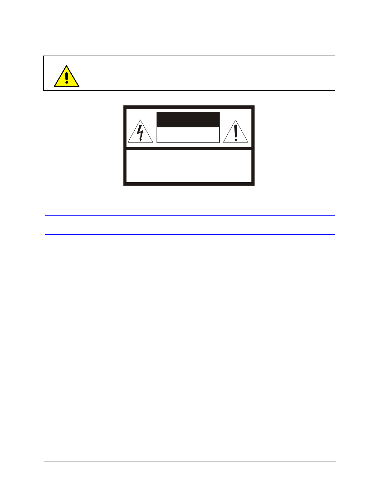
CAUTION: TO REDUCE THE RISK OF ELECTRIC SHOCK,
DO NOT REMOVE COVER (OR BA C K).
NO USER-SERVICEABLE PARTS INSIDE.
REFER SERVICING TO QUALIF IED SERVI CE PERSONNE L.
CAUTION
RISK OF ELECTRIC SHOCK
DO NO T OPE N
Using replacement parts or accessories other than the original manufacturers may invalidate the
warranty.
Important Safety Instructions
BEFORE OPERATING OR INSTALLING THE UNIT, READ AND FOLLOW ALL INSTRUCTIONS.
AFTER INSTALLATION, retain the safety and operating instructions for future reference
1. HEED WARNINGS - Adhere to all warnings on the unit and in the operating instructions.
2. INSTALLATION
• Install in accordance with the manufacturer’s instructions.
• Installation and servicing should be performed only by qualified and experienced technicians to conform to
all local codes and to maintain your warranty.
• Do not install the unit in an extremely hot or humid location, or in a place subject to dust or mechanical
vibration. The unit is not designed to be waterproof. Exposure to rain or water may damage the unit.
3. POWER SOURCES - This product should be operated only from the type of power source indicated on the
marking label. If you are not sure of the type of power supplied to your facility, consult your product dealer or
local power company.
4. HEAT - Situate away from items that produce heat or are heat sources such as radiators, heat registers, stoves,
or other products (including amplifiers).
5. WATER AND MOISTURE - Do not use this unit near water or in an unprotected outdoor installation, or any area
classified as a wet location.
6. ATTACHMENTS - Do not use attachments not recommended by the product manufacturer as they may result in
the risk of fire, electric shock, or injury to persons.
7. ACCESSORIES - Only use accessories specified by the manufacturer.
8. CLEANING - Do not use liquid cleaners or aerosol cleaners. Use a damp cloth for cleaning.
9. SERVICING - Do not attempt to service this unit yourself as opening or removing covers may expose you to
dangerous voltage or other hazards. Refer all servicing to qualified service personnel.
Document 800-07422 Rev A 7
08/10
Page 8
10. REPLACEMENT PARTS - When replacement parts are required, be sure the service technician has used
WE EE (Waste Ele ctr ical and Electronic Equipment). Correct disposal of
this product (applicable in the European Union and other European
countries with separate collection systems). This product should be
disposed of, at the end of its useful life, as per applicable local laws,
regulations, and procedures
replacement parts specified by the manufacturer or have the same characteristics as the original part.
Unauthorized substitutions may result in fire, electric shock or other hazards.
Warranty and Service
Subject to the terms and conditions listed on the Product Warranty Card, during the warranty period Honeywell will
repair or replace, at its sole option, free of charge, any defective products returned prepaid.
In the event you have a problem with any Honeywell product, call Customer Service for assistance or to request a
Return Merchandise Authorization (RMA) number. Be sure to have the model number, serial number, and the nature
of the problem available for the technical service representative.
In the U.S.A. and Canada, call 1.800.796.2288. See the back cover for other contact details.
Prior authorization must be obtained for all returns, exchanges, or credits. Items shipped to Honeywell without a
clearly identified Return Merchandise Authorization (RMA) number may be refused.
8
Page 9

UltraKey Lite Controller Installation and User Guide
Contents
1 About this Document and the UltraKey Lite . . . . . . . . . . . . . . . . . . . . . . . . . . . . . 15
Document Overview . . . . . . . . . . . . . . . . . . . . . . . . . . . . . . . . . . . . . . . . . . . . 15
Finding More Information. . . . . . . . . . . . . . . . . . . . . . . . . . . . . . . . . . . . . . . . . . 16
Typographical Conventions . . . . . . . . . . . . . . . . . . . . . . . . . . . . . . . . . . . . . . . . 16
UltraKey Lite Specifications . . . . . . . . . . . . . . . . . . . . . . . . . . . . . . . . . . . . . . . . 17
Shipping Checklist . . . . . . . . . . . . . . . . . . . . . . . . . . . . . . . . . . . . . . . . . . . . . 18
UltraKey Lite Port Connections and Descriptions . . . . . . . . . . . . . . . . . . . . . . . . . . . . .19
2 Using the UltraKey Lite Controller . . . . . . . . . . . . . . . . . . . . . . . . . . . . . . . . . . 21
Logging Onto the Controller . . . . . . . . . . . . . . . . . . . . . . . . . . . . . . . . . . . . . . . . 21
Using the UltraKey Lite to Navigate the LCD Menus. . . . . . . . . . . . . . . . . . . . . . . . . . . . 22
VideoBloX Key Functions. . . . . . . . . . . . . . . . . . . . . . . . . . . . . . . . . . . . . . . . . . 24
MAXPRO Key Functions . . . . . . . . . . . . . . . . . . . . . . . . . . . . . . . . . . . . . . . . . . 27
3 Installing UltraKey Lite with VideoBloX . . . . . . . . . . . . . . . . . . . . . . . . . . . . . . . 31
Navigating the LCD Configuration Menus . . . . . . . . . . . . . . . . . . . . . . . . . . . . . . . . . 31
Installing and Configuring a Serial Connection . . . . . . . . . . . . . . . . . . . . . . . . . . . . . . 32
Installing and Configuring an Ethernet Connection . . . . . . . . . . . . . . . . . . . . . . . . . . . . 36
(Optional) Configuring UltraKey Lite Using the Web Browser . . . . . . . . . . . . . . . . . . . . . . . 41
4 Installing UltraKey Lite with MAXPRO-Net . . . . . . . . . . . . . . . . . . . . . . . . . . . . . . 47
Navigating the LCD Configuration Menus . . . . . . . . . . . . . . . . . . . . . . . . . . . . . . . . . 47
Installing and Configuring a Serial Connection . . . . . . . . . . . . . . . . . . . . . . . . . . . . . . 49
Installing and Configuring an Ethernet Connection . . . . . . . . . . . . . . . . . . . . . . . . . . . . 56
(Optional) Configuring UltraKey Lite Using the Web Browser . . . . . . . . . . . . . . . . . . . . . . . 60
5 System Administration and Troubleshooting . . . . . . . . . . . . . . . . . . . . . . . . . . . . 65
System Administration Using the Controller LCD . . . . . . . . . . . . . . . . . . . . . . . . . . . . . 65
System Administration Using the Web Browser . . . . . . . . . . . . . . . . . . . . . . . . . . . . . . 68
Document 800-07422 Rev A 9
08/10
Page 10

10
Page 11

UltraKey Lite Controller Installation and User Guide
Figures
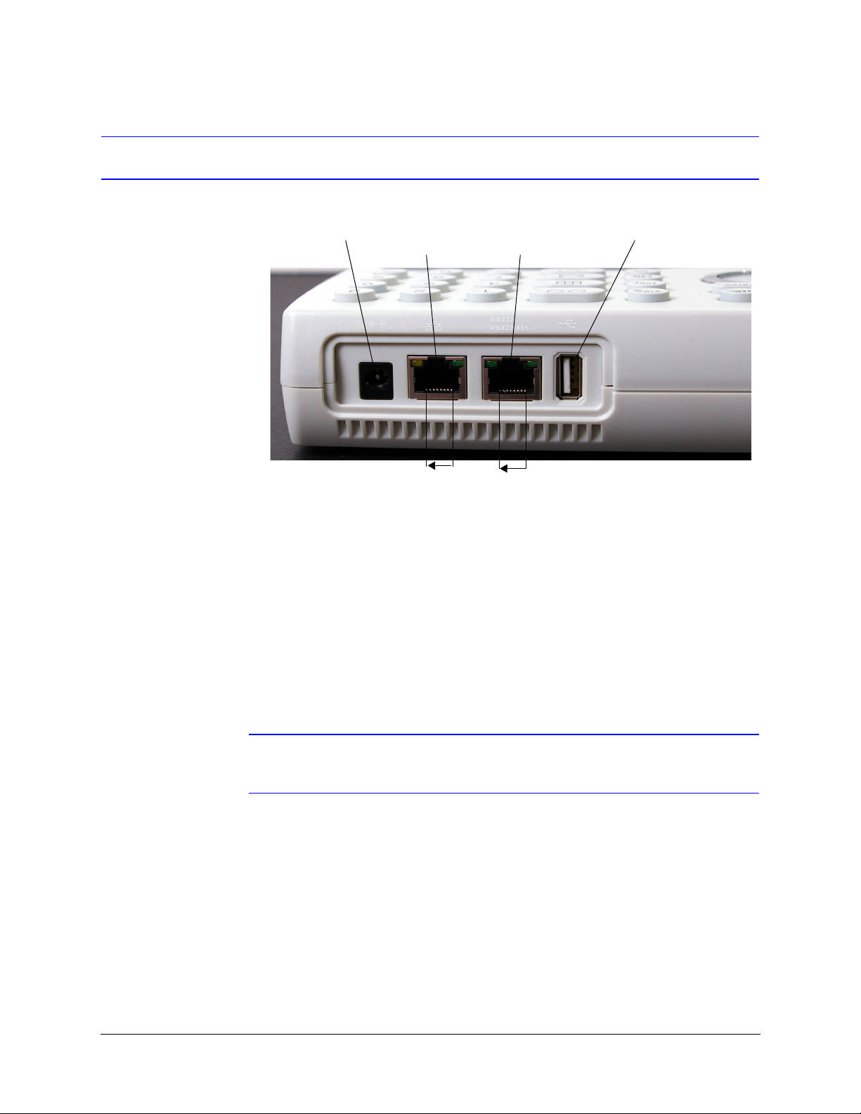
Figure 1-1 UltraKey Lite Port Connections . . . . . . . . . . . . . . . . . . . . . . . . . . . . . . . . 19
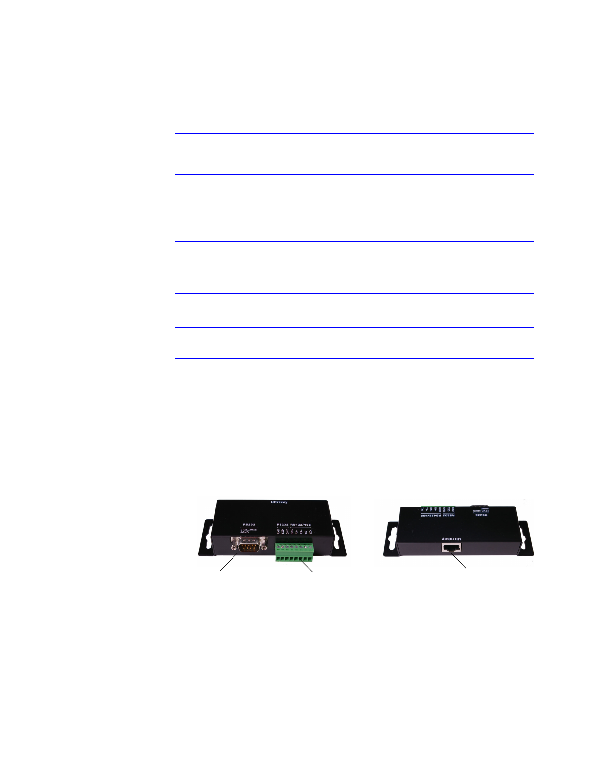
Figure 1-2 Terminal Box Front and Back Ports . . . . . . . . . . . . . . . . . . . . . . . . . . . . . . 20
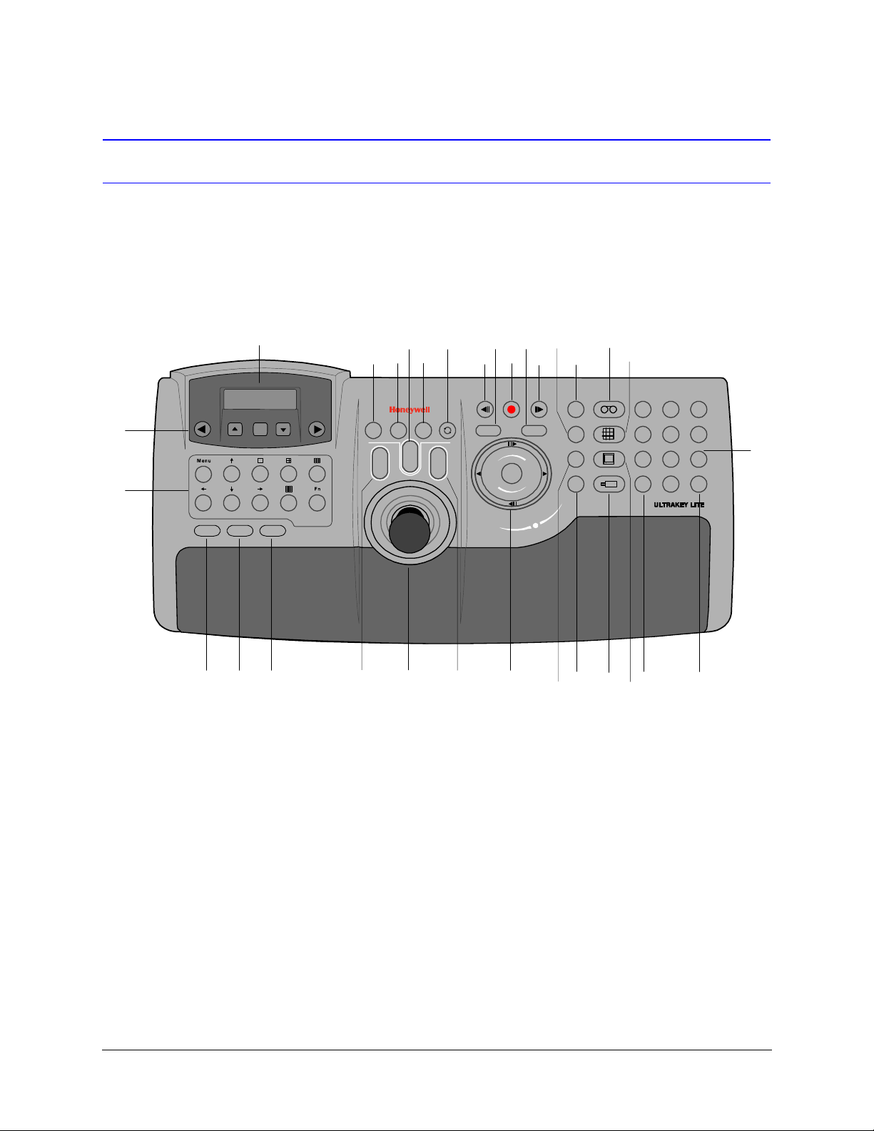
Figure 2-1 UltraKey Lite Controller Keyboard Layout . . . . . . . . . . . . . . . . . . . . . . . . . . . 22
Figure 2-2 The UltraKey Navigation Controls . . . . . . . . . . . . . . . . . . . . . . . . . . . . . . 23
Figure 3-1 LCD and LCD Navigation Keys . . . . . . . . . . . . . . . . . . . . . . . . . . . . . . . . 32
Figure 3-2 VideoBloX LCD Configuration Menu Tree . . . . . . . . . . . . . . . . . . . . . . . . . . . 32
Figure 3-3 AC Power Adapter with CEE 7/16 Europlug . . . . . . . . . . . . . . . . . . . . . . . . . 33
Figure 3-4 RJ45 to DB9 Male Adapter for VideoBloX and VideoBloX Lite CPUs . . . . . . . . . . . . . 34
Figure 3-5 Direct RJ45 Serial Port Connection for VideoBloX NetCPUs . . . . . . . . . . . . . . . . . 34
Figure 3-6 VideoBloX Serial Port RS422 Connection Example . . . . . . . . . . . . . . . . . . . . . . 34
Figure 3-7 Ethernet Port Connections to VideoBloX . . . . . . . . . . . . . . . . . . . . . . . . . . . 37
Figure 3-8 UltraKey Lite Login Page . . . . . . . . . . . . . . . . . . . . . . . . . . . . . . . . . . . 42
Figure 3-9 System Configuration Tab . . . . . . . . . . . . . . . . . . . . . . . . . . . . . . . . . . . 42
Figure 3-10 VideoBloX Configuration Tab . . . . . . . . . . . . . . . . . . . . . . . . . . . . . . . . . 43
Figure 3-11 Serial Port Configuration Tab . . . . . . . . . . . . . . . . . . . . . . . . . . . . . . . . . 44
Figure 3-12 IP Configuration Tab . . . . . . . . . . . . . . . . . . . . . . . . . . . . . . . . . . . . . . 44
Figure 3-13 DynKey Configuration Tab. . . . . . . . . . . . . . . . . . . . . . . . . . . . . . . . . . . 45
Figure 4-1 LCD and Navigation Keys . . . . . . . . . . . . . . . . . . . . . . . . . . . . . . . . . . . 48
Figure 4-2 MAXPRO LCD Menu Tree . . . . . . . . . . . . . . . . . . . . . . . . . . . . . . . . . . . 48
Figure 4-3 RS232 Serial Port Connection . . . . . . . . . . . . . . . . . . . . . . . . . . . . . . . . . 50
Figure 4-4 RS232 Serial Port Connection and MegaPIT . . . . . . . . . . . . . . . . . . . . . . . . . 50
Figure 4-5 RS232 Serial Port Connection and MX18 . . . . . . . . . . . . . . . . . . . . . . . . . . . 51
Figure 4-6 AC Power Adapter with CEE 7/16 Europlug . . . . . . . . . . . . . . . . . . . . . . . . . 51
Figure 4-7 RJ45 to DB9 Female Adapter (RS232) . . . . . . . . . . . . . . . . . . . . . . . . . . . . 51
Figure 4-8 RS422 to RS232 Converter Using the Terminal Box (RS422). . . . . . . . . . . . . . . . . 52
Figure 4-9 RS232 Serial Port Connection and Terminal Box RS422 . . . . . . . . . . . . . . . . . . . 53
Figure 4-10 RS232 Serial Port Connection, MX18 and the Terminal Box . . . . . . . . . . . . . . . . . 53
Figure 4-11 Ethernet Port Connections to MAXPRO-Net . . . . . . . . . . . . . . . . . . . . . . . . . 56
Figure 4-12 UltraKey Lite Login page. . . . . . . . . . . . . . . . . . . . . . . . . . . . . . . . . . . . 61
Figure 4-13 System Configuration Tab . . . . . . . . . . . . . . . . . . . . . . . . . . . . . . . . . . . 61
Figure 4-14 MAXPRO Configuration Tab . . . . . . . . . . . . . . . . . . . . . . . . . . . . . . . . . . 62
Figure 4-15 Serial Port Configuration Tab . . . . . . . . . . . . . . . . . . . . . . . . . . . . . . . . . 63
Figure 4-16 IP Configuration Tab . . . . . . . . . . . . . . . . . . . . . . . . . . . . . . . . . . . . . . 63
Figure 4-17 DynKey Configuration Tab . . . . . . . . . . . . . . . . . . . . . . . . . . . . . . . . . . 64
Figure 5-1 Software Upgrade Warning Message . . . . . . . . . . . . . . . . . . . . . . . . . . . . . 69
Document 800-07422 Rev A 11
08/10
Page 12

Figure 5-2 Change Password Page . . . . . . . . . . . . . . . . . . . . . . . . . . . . . . . . . . . . 69
Figure 5-3 System Configuration LCD Menu Tree - All Modes . . . . . . . . . . . . . . . . . . . . . . 70
12
Page 13

UltraKey Lite Controller Installation and User Guide
Tables
Table 1-1 UltraKey Lite Specifications. . . . . . . . . . . . . . . . . . . . . . . . . . . . . . . . . . . 17
Table 1-2 Shipping Checklist . . . . . . . . . . . . . . . . . . . . . . . . . . . . . . . . . . . . . . . 18
Table 2-1 LCD Menu Navigation During Set Up . . . . . . . . . . . . . . . . . . . . . . . . . . . . . 23
Table 2-2 VideoBloX Key Functions. . . . . . . . . . . . . . . . . . . . . . . . . . . . . . . . . . . . 24
Table 2-3 MAXPRO Key Functions . . . . . . . . . . . . . . . . . . . . . . . . . . . . . . . . . . . . 27
Table 3-1 Serial Port COM1 and COM2 Pin Assignments . . . . . . . . . . . . . . . . . . . . . . . . 33
Table 3-2 RJ45 Ethernet Pin Assignments . . . . . . . . . . . . . . . . . . . . . . . . . . . . . . . . 37
Table 3-3 Setting the Keyboard Address . . . . . . . . . . . . . . . . . . . . . . . . . . . . . . . . . 41
Table 4-1 Serial Port COM1 and COM2 Pin Assignments . . . . . . . . . . . . . . . . . . . . . . . . 49
Table 4-2 Terminal Box COM1 and COM2 Pin Assignments . . . . . . . . . . . . . . . . . . . . . . . 52
Table 4-3 RJ45 Ethernet Pin Assignments . . . . . . . . . . . . . . . . . . . . . . . . . . . . . . . . 56
Table 4-4 Setting the Keyboard Address . . . . . . . . . . . . . . . . . . . . . . . . . . . . . . . . . 60
Table 5-1 HJC5000 UltraKey Lite Controller Default Settings. . . . . . . . . . . . . . . . . . . . . . . 67
Document 800-07422 Rev A 13
08/10
Page 14

14
Page 15

1
About this Document and the UltraKey Lite
In this section:
• Document Overview, page 15
• Finding More Information, page 16
• Typographical Conventions, page 16
• UltraKey Lite Specifications, page 17
• Shipping Checklist, page 18
• UltraKey Lite Port Connections and Descriptions, page 19
The UltraKey Lite (HJC5000) is a replacement for the Honeywell HEGSBLX controller and
is compatible with Honeywell VideoBloX and MAXPRO-Net Video Matrix Systems.
The UltraKey Lite has these modes available depending on the installation:
• MAXPRO: For use with MAXPRO-Net Matrix System installations.
• VideoBloX: For use with VideoBloX Matrix System installations.
Note This installation and user guide describes the Honeywell VideoBloX and
MAXPRO-Net Video Matrix mode installation and set-up. Future product and
documentation releases will include the Standalone mode for PTZ and DVR
functionality.
Document Overview
The following is included in this user guide:
• UltraKey Lite controller user instructions (Chapter 2).
• Installation/connection and configuration instructions specific to VideoBloX
(Chapter 3) and MAXPRO-Net (Chapter 4).
• System Administration and troubleshooting (Chapter 5).
Document 800-07422 Rev A 15
08/10
Page 16

About this Document and the UltraKey Lite
Finding More Information
Refer to the online literature library to access other electronic documents in PDF format
including data sheets, quick references, installation and user guides, specifications,
software and product notices: http://www.honeywellvideo.com. Also see the back cover
for international web sites and contact details.
Typographical Conventions
This document uses these typographical conventions:
Font What it represents Example
Use of an arrow
between items >
Lucida Values of editable fields that are mentioned in
Swiss721 BT Bold Words or characters that are part of the task
Courier Text that displays on the LCD screen The LCD menu IPAddr Changed displays.
Use of an arrow between keys or tabs indicates
the order to select a menu item from the LCD or
a web browser. You may be using keys on the
controller or a mouse to click and select a tab on
a web browser
the body text of the document for reference
purposes, but do not need to be entered as part
of a procedure.
Text strings displayed on the screen.
Syntax.
process and identify a field and an action that
must be typed.
Menu titles and other items you select. Double-click Open from the File menu.
Buttons you click on a web browser to perform
actions.
Pressing a key on the keyboard.
1. On the controller, press
the System Configuration: System Set
menu.
The System Set: Mode screen displays.
The Time from field can be set to
Hours:Minute:Seconds.
The message Unauthorized displays.
(object) entered
Enter the password 1234.
Click Exit to close the program.
Press and hold Logon.
Alt > Clr to enter
Italic Placeholders: words that vary depending on the
situation.
Cross-reference to external source. Refer to the System Administrator Guide.
Cross-reference within document. See Chapter 2, Installation.
16
user name
Page 17

UltraKey Lite Specifications
Table 1-1 UltraKey Lite Specifications
Parameter Value
Power Requirements 10.8 to 13.2 VDC @ 1 Ampere (A) or POE (48 VDC, Class 3)
Connector Types 1×Ethernet (10Base-T, 100Base-TX) RJ45 with LED
LCD Type: STN, Positive Image
UltraKey Lite Controller Installation and User Guide
1×RS232/422/485 RJ45 with LED
Backlight: Blue-White
Characters: 122×32 Dots
USB Type: A
Version: USB1.1 (For USB PC Keyboard)
Compliance EN55022 for radiated and conducted emissions
Mechanical Dimensions: 408 mm (L) × 215 mm (W) × 105 mm (H)
Gross Weight: 3.2 kg
Cover material: ABS+PC (cool gray)
Environment Operating Temperature: -10 to +55 deg C
Storage Temperature: -40 to +75 deg C
Humidity: 0 to 95% RH (non-condensing)
Document 800-07422 Rev A 17
08/10
Page 18
About this Document and the UltraKey Lite
Shipping Checklist
The following is included with your UltraKey Lite Controller shipment. Use of accessories
is dependent on the type of installation. Ultrakey Lite can be connected to the matrix
system either by serial port or Ethernet RJ45 connections.
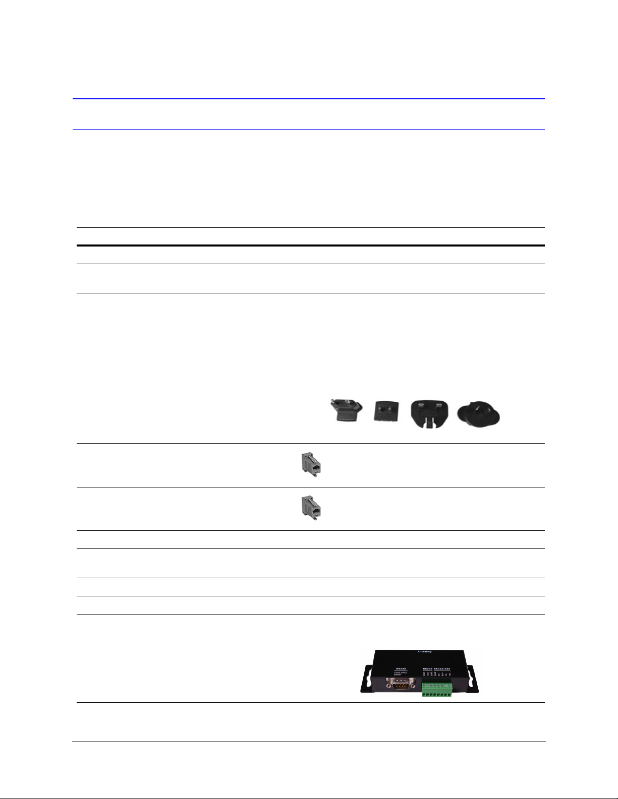
Table 1-2 Shipping Checklist
Quantity Part Use with...
1 Ultrakey Lite keyboard controller All installations.
1 Ultrakey Lite installation and user
guide
1 box Power adapter with plugs for
100-240 VAC, 12 VDC, 50-60 HZ,
1 A, 12 W
1 Connector adapter, RJ45 to DB9
male, for RS422
2 Connector adapter, RJ45 to DB9
female, for RS232
2 RJ45 network cable, 2 meters All installations.
1 RJ45 cross-over Ethernet cable, 2
meters, blue
All installations.
Plug adapters depend on local electrical current. Four
models are included:
• CEE 7/16 (Europlug 2.5 A/250V unearthed)
• NEMA 1-15 (North American 15 A/125V ungrounded)
• BS1363 (British 13A /230-240V 50 Hz earthed and
fused)
• CPCS-CCC (Chinese 10 A/250V)/AS 3112 ; Australian
10 A/240V).
Backwards compatibility with VideoBloX and
VideoBloX Lite CPU installations. VideoBloX
master port.
Backwards compatibility with MAXPRO-Net CPU
installations.
Used to connect a PC directly to the Controller for web
browser configurations.
1 RJ11 4X6 flat ribbon cable, 2 meters To connect from a MAXPRO and MX18 to the UltraKey Lite.
1 Function key overlay For use with VideoBloX installations.
1 Terminal box For additional device connection requirements.
18
Page 19
UltraKey Lite Controller Installation and User Guide
Power RJ45
Ethernet
RS232 and RS422/485
Serial port
USB
18 18
Pins numbered from right to left
UltraKey Lite Port Connections and Descriptions
Figure 1-1 UltraKey Lite Port Connections
DC Power Port
Ethernet Port
Supports 12V (±10%) DC/1 A power input. Use the power adapter included with the
shipment and insert one of the four adapters based on your local power requirements.
Note Ethernet is used to connect to the controller web browser, MAXPRO-Net or
• 10/100M Ethernet PoE (power over Ethernet) input. If PoE is the power input, it is
not recommended to connect this network with an outside building.
• TCP/IP protocol on the controller.
• For VideoBloX, the controller address range can be between 1 and 32. For
MAXPRO-Net, the address range can be between 1 and 99.
VideoBloX NetCPU.
Document 800-07422 Rev A 19
08/10
Page 20
About this Document and the UltraKey Lite
RJ45 EthernetRS232 DB9
Serial port
RS232 and RS422/485 8-pin
Terminal plug (pin numbers can
be assigned by user)
RS232, RS422/485 Serial Port
Note These ports are used to connect to MAXPRO-Net RS232 or RS422 and to
VideoBloX NetCPU, Standard CPU and Lite CPU RS422.
An isolated surge protection is suggested when using RS485/RS422 and when cabling
between buildings.
Note For MAXPRO net installations, COM1 (RS422) and COM2 (RS485) are
configured using the controller LCD menu and cannot be used at the same
time.
Terminal Box
Note Serial port 1 can be either RS485 or RS422. Serial port 2 is only RS232.
Use the terminal box RJ45 port and 8-pin terminal plug as required for compatibility and
connectivity options. It can be used to break out the RJ45 cable when wiring to existing
infrastructure is required.
Figure 1-2 Terminal Box Front and Back Ports
USB Port
20
The USB port is not used with VideoBloX or MAXPRO-net.
Page 21

2
Using the UltraKey Lite Controller
You may need to learn how to use the UltraKey Lite both before and after you begin
configuring. In this section:
• Logging Onto the Controller, page 21
• Using the UltraKey Lite to Navigate the LCD Menus, page 22
• VideoBloX Key Functions, page 24
• MAXPRO Key Functions, page 27
Note Key availability is dependent on the mode selected. Functions only used with
the Standalone Mode (for PTZ/DVR functions) are not described in this
document and will be included in future releases.
Logging Onto the Controller
1. Connect the keyboard with a power adapter (12V (±10%) DC/1 A included) or a
network cable with PoE.
2. To configure the main menu settings, press Alt > Clr.
3. Enter the PIN password 3434.
Note If an invalid password is entered, a message displays and the controller
buzzes. Repeat the steps to log on.
When you are in the Password menu, press Alt > Clr again to exit the
Password menu.
Document 800-07422 Rev A 21
08/10
Page 22
Using the UltraKey Lite Controller
32
1
65
4
98
7
0
Clr Ent
View
Tou r
PTZ
call
Alt
Review Search
Alarm Seq Set
+
Iris
—
+
Focus
—
+
Focus
—
F5
F4F3
F10F9F8
F2
F1
F7F6
Login
MonA MonB
Menu Se tup
12:00 4/6/09
Down
1
23 5 7 911
10 12 14
13 15
16
1718202123242526272829
1922
46 8
30
31
Using the UltraKey Lite to Navigate the LCD Menus
There are a variety of ways to navigate both the LCD menus during configuration and set
up as well as during normal operation with your matrix system. Figure 2-1 shows all of the
keys and other elements of the UltraKey Lite controller. See Table 2-2 for UltraKey Lite key
functions when used with a VideoBloX system. See Table 2-3 for UltraKey Lite key functions
when used with a MAXPRO-Net system.
Figure 2-1 UltraKey Lite Controller Keyboard Layout
22
See Figure 2-2 for a brief overview of the three main navigation options. See Table 2-1 for
specific methods to navigate the LCD during installation and set up.
Page 23

UltraKey Lite Controller Installation and User Guide
Touch pad - Use like a
laptop mouse pad
Right arrow key
Left arrow key
Backward or reverse key
(or down)
Forward key (or up)
Right arrow keyLeft arrow key
Up arrow key Down arrow key
Touch Pad and Ring
LCD Keys
Joystick
Move the joystick left and right or up
and down to navigate the menus
Touch pad ring
LCD
Figure 2-2 The UltraKey Navigation Controls
Document 800-07422 Rev A 23
08/10
Table 2-1 LCD Menu Navigation During Set Up
Task Options
To confirm a change or enter the
current menu
You can use any of these ways to access the LCD:
•KEYS: Press Ent
• TOUCH PAD RING: Press the right arrow key
• JOYSTICK: Move right
• LCD KEYS: Special case: to enter the Set Up menu, press the LCD center
key (not labeled)
To cancel an operation or return to
the previous level of the menu
You can use any of these ways to access the LCD:
•KEYS: Press Alt > Clr
• TOUCH PAD: Rotate your finger in a counter-clockwise motion
• TOUCH PAD RING: Press the left arrow key
• JOYSTICK: Move left
To view or switch between the
menu items of the same level
You can use any of these ways to access the LCD:
• LCD KEYS: Press up/down arrow keys
• TOUCH PAD: Rotate your finger clockwise or counter-clockwise
• TOUCH PAD RING: Press the forward/backward arrows
• JOYSTICK: Move up/down
Page 24

Using the UltraKey Lite Controller
Table 2-1 LCD Menu Navigation During Set Up (cont’d)
Task Options
To move back through the menus
one level at a time
To scroll through the top level
menu options
To scroll through the secondary
level menu options
To correct errors • KEYS: Press Clr
•KEYS: Press Alt > Clr
• LCD KEYS: Press the right/left arrow keys
• TOUCH PAD: Rotate your finger clockwise or counter-clockwise
• TOUCH PAD RING: Press the right / left arrows
• JOYSTICK: Move right/left
You can use any of these ways to access the LCD:
• LCD KEYS: Press the up/down arrow keys
• TOUCH PAD: Rotate your finger clockwise or counter-clockwise
• TOUCH PAD RING: Press the forward/backward arrows
• JOYSTICK: Move up/down
VideoBloX Key Functions
Note Use Figure 2-1 to locate each key as labeled in the ID column.
Note The keyboard supports dynamic key configuration. The key functions listed in
Table 2-2 are all default functions. Contact Honeywell Technical Support or
refer to the applicable VideoBloX manual.
Table 2-2 VideoBloX Key Functions
ID Key Description Function in Camera Mode PCK (Cam Mode) PCK (Device Mode)
2 Alarm Acknowledge Alarms Alarm Ack Alarm Ack
3 Seq Selects Sequence mode SEQ SEQ
4 Iris – Iris close – Iris C Frame <
4 Iris + Iris Open + Iris O Frame >
5 Set Store a preset (preshot) Store Stop
6 Recycle (Undo) Undo previous camera selection
(NetCPU)
<- VCR F2
24
Page 25

UltraKey Lite Controller Installation and User Guide
Table 2-2 VideoBloX Key Functions (cont’d)
ID Key Description Function in Camera Mode PCK (Cam Mode) PCK (Device Mode)
7 Pause Play Rev Selects previous camera Prev Stop
8 Review Puts keyboard in Device mode NA Pause
9 Record Store a preset (preshot) Store Rec
10 Search Puts keyboard in Device mode NA Index -
11 Pause Play Fwd Selects next camera Next Play
12 Tour Tour 1 Runs SEQ 250 on CPU
Tour 2 Runs SEQ 251 on CPU
Tour 3 Runs SEQ 252 on CPU
Tour 4 Runs SEQ 253 on CPU
13 View Recall a preset (preshot) Recall Play
14 VCR Selects Device mode VCR VCR
15 MUX Screen MUX 1 Runs SEQ 245 on CPU
MUX 2 Runs SEQ 246 on CPU
MUX 3 Runs SEQ 247 on CPU
MUX 4 Runs SEQ 248 on CPU
16 Numeric Keys 0-9 Numeric Entry Numeric Keys 0-9 Numeric Keys 0-9
17 Enter Accept entry Enter Enter
18 Clear Clear previous entry Clr Clr
19 Monitor Selects Monitor mode MON MON
20 Camera Selects Camera mode CAM CAM
22 PTZ Call Selects Alternate camera (NetCPU) Enter
23 Touch wheel right Selects next camera Next Next
23 Touch wheel left Selects previous camera Prev Prev
23 Touch ring Up Nudges PTZ Up Up Up
NA
NA Index +
23 Touch ring Down Nudges PTZ Down Down Down
23 Touch ring Left Nudges PTZ Left Left Left
23 Touch ring Right Nudges PTZ Right Right Right
25 Joystick Left Move PTZ left variable speed Joystick Left Joystick Left
25 Joystick Right Move PTZ right variable speed Joystick Right Joystick Right
25 Joystick Up Move PTZ up variable speed Joystick Up Joystick Up
25 Joystick Down Move PTZ down variable speed Joystick Down Joystick Down
25 Twist Zoom right Zoom PTZ in variable speed Twist Zoom right Twist Zoom right
25 Twist Zoom left Zoom PTZ out variable speed Twist Zoom left Twist Zoom left
27 Mon B Depends on controller address. EG,
Add 1 SEQ201 run, Add 2, SEQ202
run, and so on.
Document 800-07422 Rev A 25
08/10
NA NA
Page 26

Using the UltraKey Lite Controller
Table 2-2 VideoBloX Key Functions (cont’d)
ID Key Description Function in Camera Mode PCK (Cam Mode) PCK (Device Mode)
28 Mon A Depends on controller address. EG,
Add 1 SEQ201 run, Add 2, SEQ202
run, and so on.
29 Login Login/Logout of CPU Login Login
30 F1 F1: Define in CFG software P P
30 F2 F2: Define in CFG software BJ BJ
30 F3 F3: Define in CFG software AR AR
30 F4 F4: Define in CFG software PB PB
30 F5 F5: Define in CFG software PTZ Slots PTZ Slots
30 F6 F6: Define in CFG software PTZ Cas PTZ Cas
30 F7 F7: Define in CFG software Door Door
30 F8 F8: Define in CFG software Back House Back House
30 F9 F9: Define in CFG software Hard Count Hard Count
30 F10 F10: Define in CFG software Soft Count Soft Count
21+1 ALT + 1 Toggle Auxillary 1 Aux 1 Index -
21+2 ALT + 2 Toggle Auxillary 2 Aux 2 Index +
21+3 ALT + 3 Toggle Auxillary 3 Aux 3 CntZero
NA NA
21+30 ALT+F1 F11: Define in CFG software Cash Slots Cash Slots
21+30 ALT+F2 F12: Define in CFG software Cash Cage Cash Cage
21+30 ALT+F3 F13: Define in CFG software Group 13 Group 13
21+30 ALT+F4 F14: Define in CFG software Group 14 Group 14
21+30 ALT+F5 F15: Define in CFG software Group 15 Group 15
21+30 ALT+F6 F16: Define in CFG software Group 16 Group 16
21+4 ALT + 4 Toggle Auxillary 4 Aux 4 Memory
21+5 ALT + 5 Toggle Auxillary 5 AutoPan Data
21+6 ALT + 6 Toggle Auxillary 6 PTZ F1 VCR F1
21+7 ALT + 7 Toggle Auxillary 7 PTZ F2 VCR F2
21+8 ALT + 8 Toggle Auxillary 8 PTZ F3 VCR F3
21+F10 ALT+F10 RUN 4: Define in CFG software User 4 User 4
21+F7 ALT+F7 RUN 1: Define in CFG software User 1 User 1
21+F8 ALT+F8 RUN 2: Define in CFG software User 2 User 2
21+F9 ALT+F9 RUN 3: Define in CFG software User 3 User 3
24/26 Focus Near + Focus Near + Focus N Rew
24/26 Focus Far - Focus Far - Focus F Fwd
26
Page 27

UltraKey Lite Controller Installation and User Guide
MAXPRO Key Functions
Note Use Figure 2-1 to locate each key as labeled in the ID column.
Table 2-3 MAXPRO Key Functions
ID Key Description Key Code Default MAX Function UltraKey
2 Alarm 4 Alarm Clear Halt
3 Seq 8 Scan Select Group 2
4 Iris + 90 Iris Open Iris +
4 Iris - 91 Iris Close Iris -
5 Set 26 Set None
6 Recycle (Undo) 95 Flashback Tour
7 Pause Play Rev 80 VCR Rewind VCR Rewind
8 Review 85 Text Review
9 Record 79 Rec Rec
10 Search 77 Stop Stop
11 Pause Play Fwd 78 Play Play
12 Tour 102 PTZ Aux Flashback
13 View 74 View View
14 VCR 60 VCR None (Menu)
15 MUX Screen 50 Mux Alternate
16-1 Number 1 62 Keypad key 1 Keypad key 1
16-2 Number 2 63 Keypad key 2 Keypad key 2
16-3 Number 3 64 Keypad key 3 Keypad key 3
16-4 Number 4 66 Keypad key 4 Keypad key 4
16-5 Number 5 67 Keypad key 5 Keypad key 5
16-6 Number 6 68 Keypad key 6 Keypad key 6
16-7 Number 7 70 Keypad key 7 Keypad key 7
16-8 Number 8 71 Keypad key 8 Keypad key 8
16-9 Number 9 72 Keypad key 9 Keypad key 9
16-0 Number 0 75 Keypad key 0 Keypad key 0
17 Enter 76 Enter Enter
Document 800-07422 Rev A 27
08/10
Page 28

Using the UltraKey Lite Controller
Table 2-3 MAXPRO Key Functions (cont’d)
ID Key Description Key Code Default MAX Function UltraKey
18 Clear 808 Pause 808
19 Monitor 61 Monitor Monitor
20 Camera 73 Camera Camera
21 Alt 10 Alt Group 4
22 PTZ Call 94 Light PTZ Call
23 Touch wheel right 105 (1-8) None Shuttle R
23 Touch wheel left 106 (1-8) None Shuttle L
23 Touch ring Up 65 Up Arrow Up Arrow
23 Touch ring Down 69 Down Arrow Down Arrow
23 Touch ring Left 23 None Left Arrow
23 Touch ring Right 25 None Right Arrow
25 Joystick Left
25 Joystick Right
25 Joystick Up
25 Joystick Down
25 Twist Zoom right
25 Twist Zoom left
27 Mon B 58 F10 Monitor B
28 Mon A 57 F9 Monitor A
29 Login 41 Active None
30 F1 30 Max Menu Group 12
30 F2 65 Up Arrow Up Arrow
30 F3 1 Full Alarm
30 F4 2 2x2 None
30 F5 34 None None
30 F6 6 Left Arrow None
30 F7 69 Down Arrow Down Arrow
30 F8 7 Right Arrow Group 1
30 F9 35 None None
30 F10+F1 33 None None
21+1 F10+F2 100 Scroll Up Scroll Up
21+2 F10+F3 16 Insert None
21+3 F10+F4 17 Delete Group 5
28
Page 29

UltraKey Lite Controller Installation and User Guide
Table 2-3 MAXPRO Key Functions (cont’d)
ID Key Description Key Code Default MAX Function UltraKey
21+30 F10+F5 18 Pause Group 6
21+30 F10+F6 53 None Print Select
21+30 F10+F7 101 Scroll Down Scroll Down
21+30 F10+F8 54 F6 Freeze
21+30 F10+F9 28 Scan Halt Group 10
24/26 Focus + 89 Focus Near Focus +
24/26 Focus - 88 Focus Far Focus -
Document 800-07422 Rev A 29
08/10
Page 30

Using the UltraKey Lite Controller
30
Page 31

3
Installing UltraKey Lite with VideoBloX
In this section:
• Navigating the LCD Configuration Menus, page 31
• Installing and Configuring a Serial Connection, page 32
• Installing and Configuring an Ethernet Connection, page 36
• (Optional) Configuring UltraKey Lite Using the Web Browser, page 41
Note For all installations, refer to the applicable VideoBloX or VideoBloX Lite
installation or user guides for more information.
This section explains how to connect the UltraKey Lite controller to VideoBloX and how
to enter the basic configuration settings specific to VideoBloX. UltraKey Lite can control
the remote VideoBloX via either the serial port or the Ethernet.
Navigating the LCD Configuration Menus
Note The use of the arrow keys under the LCD is used for the following instructions.
See Figure 3-1. Also see Using the UltraKey Lite to Navigate the LCD Menus
on page 22 for detailed instructions for other ways to navigate or System
Administration Using the Controller LCD on page 65 for a configuration menu
tree.
Document 800-07422 Rev A 31
08/10
Page 32

Installing UltraKey Lite with VideoBloX
Right
arrow
key
Left
arrow
key
Up
arrow
key
Down
arrow
key
Numeric
keypad and
Ent key
Mode Selection:
VideoBloX
Connection Configuration
Serial Port Ethernet Set Up
IP Address
Address
[1 to 32]
Baud Rate Control Mode
159.099.251.230 Ethernet Serial Port
Figure 3-1 LCD and LCD Navigation Keys
Figure 3-2 VideoBloX LCD Configuration Menu Tree
Installing and Configuring a Serial Connection
Step 1: Connect to the UltraKey Lite Using the Serial Port
Note Use only COM1 when in VideoBloX mode. See Table 3-1 below.
32
Page 33

UltraKey Lite Controller Installation and User Guide
Slide plug onto the
adapter and snap
into place
Table 3-1 Serial Port COM1 and COM2 Pin Assignments
Serial Port Type Pin Signal
COM1 RS422 1 RX +
2RX –
5GND
7TX –
8TX +
RS485 7 T/R –
8T/R +
Note For a list of accessories see Shipping Checklist on page 18 and for port
connections see UltraKey Lite Port Connections and Descriptions on page 19.
1. Select the applicable adapter plug and insert it into the AC adapter. Push to click it
into place. See Figure 3-3.
2. Plug the AC adapter into the controller power port and the adapter into a power
source.
3. Connect an RJ45 network cable to the controller serial port.
4. Connect the RJ45 network cable to VideoBloX:
• For backwards compatibility with VideoBloX and VideoBloX Lite CPUs, an RJ45
to DB9 male adapter is required and included with your shipment. See Figure 3-4.
• For VideoBloX NetCPU, the installation is a direct connection with the RJ45
network cable, also included. See Figure 3-5 and Figure 3-6.
Figure 3-3 AC Power Adapter with CEE 7/16 Europlug
Document 800-07422 Rev A 33
08/10
Page 34

Installing UltraKey Lite with VideoBloX
VideoBloX
RJ45 to DB9
male adapter
Serial Port
RJ45 network cable
Controller
VideoBloX
Serial Port
RJ45 network cable
Controller
VideoBloX Serial Port (RS422)
VIdeoBlox Master
Connections
RJ45 to
DB9 Male
VB master:
1--RS422_TX –
2--RS422_TX +
3--RS422_RX +
4--RS422_RX –
5--GND
RJ45 to
DB9 Male
RJ45
Network
Cable
1
RJ45 define:
1--RS485_2+/RS422_2_TX+/
RS422_1_RX+
2--RS485_2-/RS422_2_TX-/
RS422_1_RX3—NC
4--RS232RX
5--RS232GND
6--RS232TX
7--RS485_1-/RS422_1_TX8--RS485_1+/RS422_1_TX+
*RS485_2/RS422_2_TX and
RS232 use same UART_AC
#3#4#5#1#2DB9
#8#7#5#2#1RJ45
RX+RX-GNDTX-TX+PI NOUT
Controller 1
Controller32
5
5
PSU
3
5
RJ45
Network
Cable
1
PSU
3
Figure 3-4 RJ45 to DB9 Male Adapter for VideoBloX and VideoBloX Lite CPUs
Figure 3-5 Direct RJ45 Serial Port Connection for VideoBloX NetCPUs
Figure 3-6 VideoBloX Serial Port RS422 Connection Example
Step 2: Configure the Controller for VideoBloX Mode
34
Note The controller factory defaults are VideoBloX mode, Address 1, baud rate
19200 bps. If any other mode has been selected then use the following steps
to select VideoBloX mode. Otherwise skip to Step 3: Configure Address, Baud
Rate or IP for VideoBloX Mode, page 35.
Page 35

UltraKey Lite Controller Installation and User Guide
System Set:
CONFIG
Configuration
VB Settings
Set Up
Address 4
Control Mode:
Serial Port
Set Up
IP Address
1. If not already done, install and connect the controller to a power source.
2. From the home screen, press
Set menu.
3. Enter the PIN password 3434.
The System Set: Mode screen displays.
4. Press the LCD right arrow key to enter the Mode Selection menu.
5. Scroll to and select VideoBloX. Press Ent.
Alt > Clr to enter the System Configuration: System
Step 3: Configure Address, Baud Rate or IP for VideoBloX Mode
1. Press Alt > Clr. If prompted, enter the password 3434 to enter the System Set top
menu.
2. Press the LCD down arrow to scroll to the System Set:
Config menu.
3. Press the right arrow key to enter the Configuration menus.
4. Press the LCD up/down arrow keys to scroll through the options (restore default, VB
settings, maxpro settings, network, language, back light, slider update, hardware test,
about).
5. Scroll to the Configuration: VB Settings menu, then press
Ent.
6. Press the LCD right arrow key to scroll to enter the VB
Settings menu.
7. Press the right arrow key to scroll through the Set Up menu
to the Control Mode submenu. The current setting is
displayed (Serial Port or Ethernet).
8. Press the up/down arrow keys to scroll to Serial Port then press Ent.
9. Press the LCD right arrow key to scroll to Set Up: Address.
10. Use the LCD up/down arrow keys to scroll to an address between 1 and 32 to assign
to the controller. You can also use the numeric keypad to enter a number between 1
and 32. However, if you enter a number greater than 32, the message Invalid ID
displays on the LCD.
11. Press Ent.
12. Press the LCD right arrow key to scroll to Set Up: Baud Rate.
13. Press the LCD up/down arrow keys to select a baud rate. 1200 bps, 9600, 19.2 KB
(default for VideoBloX) or 57.6 KB bps are available for VideoBloX.
14. Press Ent.
15. If you are using the TCP/IP to connect to a VideoBloX
NetCPU, then press the LCD right arrow key to scroll to Set
Up: IP Address. Press Ent.
Document 800-07422 Rev A 35
08/10
Page 36

Installing UltraKey Lite with VideoBloX
IP Address
159.099.251.230
Time Left 3
Note In this field, you are setting the VideoBloX NetCPU IP address. To set the
UltraKey Lite IP address or enter the main configuration menus, press Alt >
Clr and see Step 3: Set and Configure for an Ethernet Connection on page 38.
16. Use the numeric keypad to enter an IP address as required,
then press Ent.
Step 4: Configure VideoBloX Mode Default Settings While Powering Up
1. While powering up, when the Time Left 3 menu displays, press Alt > Camera to set
the VideoBlox mode.
2. Set the corresponding serial port as:
Baud Rate: 19.2 KB
Data Bit: 8
Parity: None
Stop Bit: 1
Installing and Configuring an Ethernet Connection
For a list of accessories see Shipping Checklist on page 18 and for port connections and
pin assignments see UltraKey Lite Port Connections and Descriptions on page 19. The
UltraKey Lite Controller runs TCP/IP keyboard protocol.
Step 1: Connect to the UltraKey Lite Ethernet Port
Note The direct RJ45 connection using the Ethernet port is only available with
newer model VideoBloX NetCPU systems.
36
Page 37

UltraKey Lite Controller Installation and User Guide
VideoBloX
Ethernet Port
RJ45 network cables
Ethernet Port
Controller 1
Controller 32
TCP/IP
TCP/IP
Network
Table 3-2 RJ45 Ethernet Pin Assignments
Port Pin Signal
RJ45 Ethernet 1 TX +
2TX –
3RX+
6RX –
1. Select the applicable adapter plug and insert it into the AC adapter. Push to click it
into place. See Figure 3-3.
2. Plug the AC adapter into the controller power port and the adapter into a power
source.
3. Plug an RJ45 network cable from the network to the controller Ethernet port. Up to 32
controllers can be connected to the network. See Figure 3-7.
4. Connect VideoBloX to the network. Refer to the applicable VideoBloX Installation
Guide for instructions.
Figure 3-7 Ethernet Port Connections to VideoBloX
Step 2: Configure the Controller for VideoBloX Mode
Note The controller factory defaults are VideoBloX mode, Address 1, baud rate
19200 bps. If any other mode has been selected then see Step 2: Configure
the Controller for VideoBloX Mode on page 34 to select VideoBloX mode.
Otherwise skip to the next step.
Document 800-07422 Rev A 37
08/10
Page 38

Installing UltraKey Lite with VideoBloX
System Set:
CONFIG
Configuration
VB Settings
Set Up
Address 4
Control Mode:
Ethernet
IP Address
159.099.251.230
System Set:
CONFIG
Step 3: Set and Configure for an Ethernet Connection
1. Press Alt > Clr. If prompted, enter the password 3434 to enter the System Set top
menu.
2. Press the LCD down arrow to scroll to the System Set:
Config menu.
3. Press the right arrow key to enter the Configuration menus.
4. Press the LCD up/down arrow keys to scroll through the options (restore default, VB
settings, maxpro settings, network, language, back light, slider update, hardware test,
about).
5. Scroll to the Configuration: VB settings menu, then press
Ent.
6. Press the right arrow key to enter the Set Up menu.
7. Press the right arrow key to scroll through the Set Up menu
to the Control Mode submenu. The current setting is
displayed (Serial Port or Ethernet).
8. Press the LCD up/down arrow keys to scroll to Ethernet.
9. Press Ent.
The Set Up: IP Address menu displays.
10. Press Ent.
Note In this field, you are setting the VideoBloX NetCPU IP address. To set the
UltraKey Lite IP address or enter the main configuration menus, press Alt >
Clr.
11. Use the numeric keypad to enter an IP address as required,
then press Ent.
12. Press the LCD right arrow key to scroll to Set Up: Address.
13. Use the LCD up/down arrow keys to scroll to an address between 1 and 32 to assign
to the controller. You can also use the numeric keypad to enter a number between 1
and 32. However, if you enter a number greater than 32, the message Invalid ID
displays on the LCD.
14. Press Ent.
Step 4: Configure the Controller for an Ethernet Connection
1. Press Alt > Clr to exit from the VideoBloX configuration menu.
2. Press Alt > Clr a second time to enter the System Set top menu.
3. Press the LCD down arrow key to scroll to the System Set:
Config menu.
4. Press the right arrow key to enter the Configuration menus.
38
Page 39

UltraKey Lite Controller Installation and User Guide
Configuration
Network
Network
Show Net Infor DHCP
Manual Setting
Network:
DHCP
Network:
Show Net Infor
Network:
Manual Setting
Network:
DHCP
Please wait....
Succeeded!
Failed!
Network:
Manual Setting
5. Press the LCD up/down arrow keys to scroll through the options (serial port, network,
language, back light, slider update, cascade linkage, hardware test, about).
6. Scroll to the Configuration: Network menu, then press
Ent.
7. There are three sub-menus in this menu (Show Net Infor,
DHCP, and Manual Settings). The structure is as follows:
Show Net Infor Menu
The Show Net Infor Menu displays the Network information, including IP Address, DNS,
Gateway, and Netmask.
Automatically Configuring the Network Using DHCP
The Dynamic Host Configuration Protocol (DHCP) is a computer networking protocol used
by devices (DHCP clients) to obtain configuration information for operation in an Internet
Protocol network. It is used to configure the network automatically.
Automatically configuring the network using the DHCP menu:
1. Press the LCD down arrow to scroll to the Network: DHCP
menu.
2. Press Ent and the keyboard's network will be configured
automatically.
• If the network configuration is successfull, then a
Succeeded! message displays.
• If the network configuration was not successful, then a
Failed! message displays.
When the nework configures successfully, the user can enter the
Show Net Infor menu to see the IP Address, IP Address, DNS,
Gateway and Netmask.
Manually Configuring the Network
Document 800-07422 Rev A 39
08/10
Manually configuring the network using the Manual Setting menu:
1. Press the LCD down arrow key to scroll to the Network: Manual Setting menu
Page 40

Installing UltraKey Lite with VideoBloX
Network:
IP Address
IP Address
159.099.251.230
IP Addr Changed
Yes
2. When you are at the Network: Manual Setting menu, press Ent, then press the LCD
up/down arrow keys to set the UltraKeyLite network parameters (IP address, gateway,
netmask and DNS).
3. Press the LCD up/down arrow keys to scroll through the
menu options to select IP Address, then press Ent to
select.
a. Using the numeric key pad, enter an IP address, then
b. Press the up/down arrow keys to select Yes to save or
Note In this field, you are setting the UltraKey Lite IP address. To set the VideoBloX
press Ent to save.
The LCD menu displays the message: IPAddr
Changed.
No to cancel, then press Ent.
IP address (for communication purposes), see Step 3: Set and Configure for
an Ethernet Connection.
4. Press the LCD up/down arrow keys
Gateway. Press Ent.
a. Using the number keys, enter a Gateway as required, then press Ent to save.
The LCD menu displays the message: GW Changed.
b. Press the up/down arrow keys to select Yes to save or No to cancel, then press
Ent.
5. Press the LCD up/down arrow keys to scroll through the menu options and select
NetMask. Press Ent.
a. Using the number keys, enter a NetMask as required, then press Ent to save.
The LCD menu displays the message: NetMsk Changed.
b. Press the up/down arrow keys to select Yes to save or No to cancel, then press
Ent.
6. Press the LCD up/down arrow keys to scroll through the menu options and select
DNS. Press Ent.
a. Using the number keys, enter a DNS as required, then press Ent to save.
The LCD menu displays the message: DNS Changed.
b. Press the up/down arrow keys to select Yes to save or No to cancel, then press
Ent to save.
to scroll through the menu options and select
40
Page 41

UltraKey Lite Controller Installation and User Guide
Step 5: Setting the Keyboard Address While Powering Up
While powering up, when the Time Left 3 menu displays, press certain keys (see Table 3-3)
to set the keyboard address.
Table 3-3 Setting the Keyboard Address
Key Address Key Address
Alt > 1 1 Alt > F1 11
Alt > 2 2 Alt > F2 12
Alt > 3 3 Alt > F3 13
Alt > 4 4 Alt > F4 14
Alt > 5 5 Alt > F5 15
Alt > 6 6 Alt > F6 16
Alt > 7 7 Alt > F7 17
Alt > 8 8 Alt > F8 18
Alt > 9 9 Alt > F9 19
Alt > 0 10 Alt > F10 20
(Optional) Configuring UltraKey Lite Using the Web Browser
Logging into the Web Browser
1. If not already done, navigate to, or copy and paste, the applicable IP address into
your web browser:
• LAN connections: for example, http://192.168.1.9
• Crossover cable connections: for example, http://192.168.1.9 (default)
2. In the User Name field enter Administrator (case sensitive).
3. In the Password field enter 1234 (default).
4. Click Login.
Document 800-07422 Rev A 41
08/10
Page 42

Installing UltraKey Lite with VideoBloX
Figure 3-8 UltraKey Lite Login Page
Step 1: Configure UltraKey Lite to VideoBloX Mode
1. Log into the web browser.
2. From the top menu, click the Configuration tab. See Figure 3-9.
3. From the side menu, click the System Configurations tab.
4. From the System Mode drop down list, select VideoBlox.
5. From the System Language drop down list, select English or French.
6. From the Background Light drop down list select ON or OFF.
7. Click Apply to save the configuration, Cancel to exit without saving or Default to
restore all factory default values.
Figure 3-9 System Configuration Tab
Step 2: Configure VideoBloX Network Settings
42
1. From the side menu, click VideoBloX Configuration. See Figure 3-10.
2. Under Keyboard ID Setting, enter a number between 1 and 32 to set the controller
ID.
Page 43

UltraKey Lite Controller Installation and User Guide
Note By default, addresses 1– 5 in the VideoBloX NetCPU are set for serial
connection. Please change this in the NetCPU configuration if you want to
use addresses 1– 5 for Ethernet connection.
3. Under VB Device Network Setting, enter the IP address and Port Number of the
VideoBloX system.
4. Click Apply to save the configuration, Cancel to exit without saving, or Default to
restore all factory default values.
5. Go to either Step 3A or 3B to configure the system for Serial or Ethernet connections
respectively.
Figure 3-10 VideoBloX Configuration Tab
Checking the Network Connection Using the Ping Function
After the IP address is entered and applied, press the Ping button.
• A green Ping button indicates the device at this IP address has replied to the ping.
• A red Ping button indicates the device at the IP address did not reply. Please check
that the IP address is correct and that there is a valid network path between the two IP
addresses.
Step 3A: Configure the Controller for a Serial Port Connection
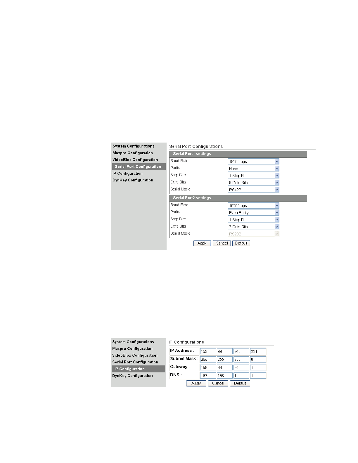
1. From the side menu, click Serial Port Configuration. See Figure 3-11.
Document 800-07422 Rev A 43
08/10
Page 44
Installing UltraKey Lite with VideoBloX
2. Under Serial Port1 Settings, select the following from each drop-down list as
required:
• Baud Rate: 1200, 9600, 19200 or 57600 bps.
• Parity: none
• Stop Bits: 1 bit
• Data Bits: 8 bits
• Serial Mode: RS422
3. Click Apply to save the configuration, Cancel to exit without saving, or Default to
restore all factory default values.
Figure 3-11 Serial Port Configuration Tab
The default for VideoBloX is 19200.
Step 3B: Configure the Controller for an Ethernet Connection
1. From the side menu, click IP Configuration. See Figure 3-12.
2. In each of the fields, enter IP address, subnet mask, gateway and DNS values.
3. Click Apply to save the configuration, Cancel to exit without saving, or Default to
restore all factory default values.
Figure 3-12 IP Configuration Tab
44
Page 45

Step 4: Configuring the Dynamic Keys
You can configure the hard keys on the web server.
1. From the side menu, click DynKey Configuration.
Figure 3-13 DynKey Configuration Tab
UltraKey Lite Controller Installation and User Guide
2. In the drop-down menu, select the key you want to configure.
3. In the right column, select the function you want to add to the hard key, then click
Add.
That selected function appears in the center column.
4. Repeat step 3 to add another function to the selected hard key.
5. Click Apply to save.
Note No more than 10 functions can be configured to a hard key.
Note Neither the number key (#) nor the Logon key can be configured.
Document 800-07422 Rev A 45
08/10
Page 46

Installing UltraKey Lite with VideoBloX
46
Page 47

4
Installing UltraKey Lite with MAXPRO-Net
In this section:
• Navigating the LCD Configuration Menus, page 47
• Installing and Configuring a Serial Connection, page 49
• Installing and Configuring an Ethernet Connection, page 56
• (Optional) Configuring UltraKey Lite Using the Web Browser, page 60
Note For all installations, refer to the applicable MAXPRO-Net installation or user
guides for more information.
This section explains how to connect the UltraKey Lite controller to MAXPRO-Net and how
to enter the basic configuration settings specific to MAXPRO-Net. For other user
configurations see the index or table of contents.
Navigating the LCD Configuration Menus
Note The use of the arrow keys under the LCD is used for the following instructions.
See Figure 4-1. Also see Using the UltraKey Lite to Navigate the LCD Menus
on page 22 for detailed instructions for other ways to navigate or System
Administration Using the Controller LCD on page 65 for a configuration menu
tree.
Document 800-07422 Rev A 47
08/10
Page 48

Installing UltraKey Lite with MAXPRO-Net
Right
arrow
key
Left
arrow
key
Up
arrow
key
Down
arrow
key
Numeric
keypad and
Ent key
Mode Selection:
MAXPRO
_59/099.251.132
Maxpro offline
keyboard 1
Maxpro Key CodeConfigurationConnection
RS232 directly RS422 indirectly Maxpro Setting
Fixed Camera
Camera 1
By Serial Port By Ethernet
Serial Port ModeSerial PortJoystick Speed Server IPKeyboard ID Baud Rate
1 to 32 9600 / 19200 bps Normal / High 26024 RS232 / RS485
Figure 4-1 LCD and Navigation Keys
Figure 4-2 MAXPRO LCD Menu Tree
From the MAXPRO settings menu, you set the following based on either a Serial or Ethernet
connection:
• Keyboard ID (address) - Serial or Ethernet connections
• Baud rate - Serial connections only
• Joystick speed - Serial or Ethernet connections
• Server IP - Ethernet connections only
• Server Port - Ethernet connections only
• Serial port mode - Serial connections only
48
Page 49

UltraKey Lite Controller Installation and User Guide
Installing and Configuring a Serial Connection
Step 1: Connect to the UltraKey Lite Serial Port
Note For a list of accessories see Shipping Checklist on page 18 and for port
connections see UltraKey Lite Port Connections and Descriptions on page 19.
Note COM1 (RS422) and COM2 (RS485) are configured using the controller LCD
menu and cannot be used at the same time. See Table 4-1 below.
Table 4-1 Serial Port COM1 and COM2 Pin Assignments
Serial Port Type Pin Signal
COM1 RS422 1 RX +
2RX –
5GND
7TX –
8TX +
RS485 7 T/R –
8T/R +
COM2 RS232 4 RXD
5GND
6TXD
RS485 1 T/R +
2T/R –
Document 800-07422 Rev A 49
08/10
Page 50

Installing UltraKey Lite with MAXPRO-Net
MAXPRO Serial Port (RS232)
RJ45 to
DB9 female
#2(RX)#5(GND)#3(TX)DB9(Maxpro)
#6(TX)#5(GND)#4(RX)RJ45 (Ultrakey Lite)
RJ45 to DB9 female
RJ45 to
DB9 female
RJ45 define:
1--RS485_2+/RS422_2_TX+/
RS422_1_RX+
2--RS485_2-/RS422_2_TX-/
RS422_1_RX3—NC
4--RS232RX
5--RS232GND
6--RS232TX
7--RS485_1-/RS422_1_TX8--RS485_1+/RS422_1_TX+
*RS485_2/RS422_2_TX and
RS232 use same UART_AC
Controller 1
Controller 16
4
4
4
RJ45
Network
Cable
1
RJ45
Network
Cable
1
PSU
3
PSU
3
Controller 1
Controller 8
RS232
MEGAPIT - 1
Controller 249
RS232
Controller 256
MEGAPIT - 32
MEGAPIT
1--RS422_TX+
2--RS422_TX3--NC
4--RS232TX
5--RS232GND
6--RS232RX
7--RS422_RX8--RS422_RX+
RJ45 define:
1--RS485_2+/RS422_2_TX+/
RS422_1_RX+
2--RS485_2-/RS422_2_TX-/
RS422_1_RX3—NC
4--RS232RX
5--RS232GND
6--RS232TX
7--RS485_1-/RS422_1_TX8--RS485_1+/RS422_1_TX+
*RS485_2/RS422_2_TX and
RS232 use same UART_AC
MAXPRO Serial Port (RS232) and MegaPIT
RJ45
Network
Cable
1
PSU
3
PSU
3
Figure 4-3 RS232 Serial Port Connection
Figure 4-4 RS232 Serial Port Connection and MegaPIT
50
Page 51

UltraKey Lite Controller Installation and User Guide
Controller 1
Controller 8
MX18
RJ11 Flat
Ribbon
Cable -
straight
RJ11 Flat
Ribbon
Cable straight
RJ45 define:
1--RS485_2+/RS422_2_TX+/
RS422_1_RX+
2--RS485_2-/RS422_2_TX-/
RS422_1_RX3—NC
4--RS232RX
5--RS232GND
6--RS232TX
7--RS485_1-/RS422_1_TX8--RS485_1+/RS422_1_TX+
*RS485_2/RS422_2_TX and
RS232 use same UART_AC
7
7
MAXPRO Serial Port (RS232) and MX18
PSU
3
PSU
3
Slide plug onto the
adapter and snap
into place
MAXPRO-Net
RJ45 to DB9
female adapter
Serial Port (RS232)
RJ45 network cable
Figure 4-5 RS232 Serial Port Connection and MX18
Document 800-07422 Rev A 51
08/10
RS232 Connections with an RJ45 to DB9 Female Adapter
1. Select the applicable adapter plug and insert it into the AC adapter. Push to click it
into place. See Figure 4-6.
Figure 4-6 AC Power Adapter with CEE 7/16 Europlug
2. Plug the AC adapter into the controller power port and the adapter into a power
source.
3. Connect an RJ45 network cable to the controller serial port.
4. Connect the RJ45 network cable to MAXPRO-Net. For RS232 backwards compatibility
with MAXPRO-Net CPUs, plug the RJ45 to DB9 female adapter included with your
shipment into the applicable port of MAXPRO-Net. See Figure 4-7.
Figure 4-7 RJ45 to DB9 Female Adapter (RS232)
Page 52

Installing UltraKey Lite with MAXPRO-Net
MAXPRO-Net
RS422 to RS232
converter
Serial Port (RS422)
Terminal Box
RJ45 network cable
RS232
Ethernet Port
RS422 COM1
Controller
RS422 Connections Using a Converter and the Terminal Box
1. Select the applicable adapter plug and insert it into the AC adapter. Push to click it
into place. See Figure 4-6.
2. Connect an RJ45 network cable from the RJ45 port on the terminal box to the
controller serial port.
3. Connect an RS422 cable from the RS422 terminal plug pins on the terminal box to an
RS422 to RS232 converter (supplied by the installer or customer).
4. Connect the RS422 to RS232 converter to the MAXPRO-Net RS232 port. See
Figure 4-8.
Figure 4-8 RS422 to RS232 Converter Using the Terminal Box (RS422)
Table 4-2 Terminal Box COM1 and COM2 Pin Assignments
Location Serial Port Type Pin Signal
DB9 Port COM2 RS232 2 TXD
3RXD
5GND
Terminal Plug COM1 RS422 1 TX+
2TX –
3RX+
4RX –
5GND
RS485 1 TX+
2TX –
COM2 RS232 6 GND
7TXD
8RXD
RS485 3 RX+
4RX –
52
Page 53

UltraKey Lite Controller Installation and User Guide
RS422
RS232
to
RS422
RS232
to
RS422
232SR232SR
RS422
PL2
RJ45
PL1
DB9 male
PL1
1--RS485_1+/RS422_1_TX+
2--RS485_1-/RS422_1_TX3--RS485_2+/RS422_2_TX+
/RS422_1_RX+
4--RS485_2-/RS422_2_TX/RS422_1_RX5--RS232RX
6--RS232TX
7--RS232GND
8--RS232GND
*RS485_2/RS422_2_TX and
RS232 use same UART_AC
PL2
RJ45
PL1
Terminal Box
DB9 male
Controller 1
Controller 16
2
2
MAXPRO Serial Port (RS232) and Terminal Box (RS422)
RJ45
Network
Cable
1
RJ45
Network
Cable
1
PSU
3
PSU
3
Controller 1
Controller 8
MX18
PL2
RJ45
PL1
Terminal Box
DB9 male
PL2
RJ45
PL1
Terminal Box
DB9 male
PL1
1--RS485_1+/RS422_1_TX+
2--RS485_1-/RS422_1_TX3--RS485_2+/RS422_2_TX+
/RS422_1_RX+
4--RS485_2-/RS422_2_TX/RS422_1_RX5--GND
6--GND
7--RS232TX
8--RS232RX
*RS485_2/RS422_2_TX and
RS232 use same UART_AC
2
2
MAXPRO Serial Port (RS232), MX18 and Terminal Box
RJ45
Network
Cable
1
RJ45
Network
Cable
1
PSU
3
PSU
3
Figure 4-9 RS232 Serial Port Connection and Terminal Box RS422
Document 800-07422 Rev A 53
08/10
Figure 4-10 RS232 Serial Port Connection, MX18 and the Terminal Box
Page 54

Installing UltraKey Lite with MAXPRO-Net
Maxpro Loading.
FIXED CAMERA
Camera 1
Maxpro offline
Keyboard 1
System Set:
CONFIG
Configuration
Maxpro Settings
Step 2: Configure the Controller for MAXPRO Mode
Note The controller factory defaults to VideoBloX mode, Address 1, baud rate
19200 bps.
1. If not already done, install and connect the controller to a power source.
The UltraKey Lite LCD displays.
2. From the home screen, press Alt > Clr to enter the System Configuration: System
Set menu.
3. Enter the PIN password 3434.
The System Set: Mode screen displays.
4. Press the LCD right arrow key to enter the Mode Selection menu.
5. Scroll to and select MAXPRO. Press Ent.
6. From the home screen, press Alt > Clr to enter the System Configuration: System
Set menu.
The System Set: Mode screen displays.
7. Press the LCD right arrow key to enter the Mode Selection menu.
8. Scroll to and select MAXPRO. Press Ent. MAXPRO
Loading displays and one of two screens display:
• If the controller is able to connect to the MAXPRO
network, the LCD displays the connection, for example,
fixed camera 1 has sent a signal from MAXPRO to
the controller.
• If the controller is not able to connect to the MAXPRO
network, the offline menu displays If this menu
displays, you cannot configure the serial or ethernet
connections in the next step.
Step 3: Configure Address, Baud Rate, or IP for MAXPRO-Net mode
1. Press Alt > Clr. If prompted, enter the password 3434 to
enter the System Setup: Config menu.
2. Press the right LCD arrow key to enter the Configuration
menus.
3. Press the LCD up/down arrow keys to scroll through the
options (restore default, VB settings, maxpro settings,
network, language, back light, slider update, hardware test,
about).
Scroll to the Configuration: Maxpro settings menu, then press Ent.
4. Select By Serial Port from the MAXPRO connection submenu, then press Ent.
54
Page 55

UltraKey Lite Controller Installation and User Guide
Maxpro Settings
SerialPortMode:
Maxpro Settings
Server IP:
MaxproServer IP
_59.099.251.132
Maxpro Settings
Server Port:
Time Left 3
Note If the controller cannot connect to the MAXPRO network, then this step
cannot be completed until the connection is established. However, the
MAXPRO settings menu can be configured even if the controller has not
connected to the MAXPRO network; that is, the LCD displays that MAXPRO is
offline.
5. Use the LCD up/down arrow keys to select RS232 or RS422, then press Ent.
6. Use the LCD up/down arrow keys to scroll to an address between 1 and 99 to assign
to the controller, then press Ent to save.
7. Press the down LCD arrow key to scroll to Baud Rate. Press Ent and use the
up/down arrow keys to select a baud rate of 9600 bps or 19200 bps for the controller.
Press Ent to save.
Note 19200 bps is the default baud rate for most MAXPRO systems.
8. Press the down LCD arrow key to scroll to Joystick Speed. Press Ent and use the
up/down arrow keys to select Normal or High. Press Ent to save.
9. Press the down LCD arrow key to scroll to Serial Port
Mode. Press Ent and use the up/down arrow keys to select
RS232 or RS422. Press Ent to save.
Note In the following fields, you are setting the MAXPRO-Net Server IP address and
port number. To set the UltraKey Lite IP address or enter the main
configuration menus, press Alt > Clr.
10. Press the down LCD arrow key to scroll to Server IP. Press
Ent and use the up/down arrow keys or the numeric keys to
enter the Server IP address. Press Ent to save.
11. Press the down LCD arrow key to scroll to Server Port.
Press Ent and use the up/down arrow keys or the numeric
keys to enter the Server Port Address. Press Ent to save.
12. After the MAXPRO settings are complete, press Alt > Clr to
exit the Setup menu.
Step 4: Configure MAXPRO Mode Default Settings While Powering Up
Document 800-07422 Rev A 55
08/10
1. While powering up, when the Time Left 3 menu displays,
press Alt > Monitor to set the Maxpro mode.
2. Set the corresponding serial port as:
Page 56

Installing UltraKey Lite with MAXPRO-Net
Ethernet Port
RJ45 Network cables
Ethernet Port
Controller 1
Controller 32
TCP/IP
TCP/IP
Network
MAXPRO-Net
TCP/IP
Baud Rate: 19.2 KB
Data Bit: 7
Parity: Even
Stop Bit: 1
Installing and Configuring an Ethernet Connection
Step 1: Connect to the UltraKey Lite Ethernet Port
Table 4-3 RJ45 Ethernet Pin Assignments
Port Pin Signal
RJ45
Ethernet
1. Plug an RJ45 network cable from the network to the controller Ethernet port. Up to 99
controllers can be connected to the network. See Figure 4-11.
2. Connect MAXPRO-Net to the network. Refer to the applicable MAXPRO-Net
Installation Guide for instructions.
Figure 4-11 Ethernet Port Connections to MAXPRO-Net
1TX +
2TX –
3RX+
6RX –
56
Page 57

UltraKey Lite Controller Installation and User Guide
Maxpro Settings
Keyboard ID:
Maxpro Settings
Server IP:
MaxproServer IP
_59.099.251.132
Maxpro Settings
Server Port:
Step 2: Configure the Controller for MAXPRO Mode
Note The controller factory defaults to VideoBloX mode, Address 1, baud rate
19200 bps. Follow the same steps as with the serial connection, Step 2:
Configure the Controller for MAXPRO Mode on page 54.
Step 3: Set and Configure for an Ethernet Connection
1. From the MAXPRO connection submenu, select Ethernet.
Note If the controller cannot connect to the MAXPRO network, then this first step
cannot be completed until the connection is established. However, the
MAXPRO settings menu can be configured even if the controller has not
connected to the MAXPRO network; that is, the LCD displays that MAXPRO is
offline.
2. Press the LCD center key.
The Maxpro Settings: Keyboard ID menu opens.
3. Press Ent.
4. Use the LCD up/down arrow keys to scroll to an address between 1 and 99 to assign
to the controller.
5. Press Ent to save.
6. Press the down LCD arrow key to scroll to Joystick Speed. Press Ent and use the up/
down arrow keys to select Normal or High. Press Ent to save.
Note In the following fields, you are setting the MAXPRO-Net Server IP address and
port number. To set the UltraKey Lite IP address or enter the main
configuration menus, press Alt > Clr.
7. Press the down LCD arrow key to scroll to Server IP. Press
Ent and use the up/down arrow keys or the numeric keys to
enter the Server IP address. Press Ent to save.
8. Press the down LCD arrow key to scroll to Server Port.
Press Ent and use the up/down arrow keys or the numeric
keys to enter the Server Port Address. Press Ent to save.
9. After the MAXPRO settings are complete, press Alt > Clr to
exit the setup menu.
Document 800-07422 Rev A 57
08/10
Page 58

Installing UltraKey Lite with MAXPRO-Net
System Set:
CONFIG
Configuration
Network
Network
Show Net Infor DHCP
Manual Setting
Network:
DHCP
Network:
Show Net Infor
Network:
Manual Setting
Network:
DHCP
Please wait....
Succeeded!
Failed!
Step 4: Configure the Controller for an Ethernet Connection
1. Press Alt > Clr to exit from the VideoBloX configuration menu.
2. Press Alt > Clr a second time to enter the System Set top menu.
3. Press the LCD down arrow key to scroll to the System Set:
Config menu.
4. Press the right arrow key to enter the Configuration menus.
5. Press the LCD up/down arrow keys to scroll through the options (serial port, network,
language, back light, slider update, cascade linkage, hardware test, about).
6. Scroll to the Configuration: Network menu, then press
Ent.
7. There are three sub-menus in this menu (Show Net Infor,
DHCP, and Manual Settings). The structure is as follows:
Show Net Infor Menu
The Show Net Infor Menu displays the Network information, including IP Address, DNS,
Gateway, and Netmask.
Automatically Configuring the Network Using DHCP
The Dynamic Host Configuration Protocol (DHCP) is a computer networking protocol used
by devices (DHCP clients) to obtain configuration information for operation in an Internet
Protocol network. It is used to configure the network automatically.
Automatically configuring the network using the DHCP menu:
1. Press the LCD down arrow to scroll to the Network: DHCP
menu.
2. Press Ent and the keyboard's network will be configured
automatically.
• If the network configuration is successfull, then a
Succeeded! message displays.
• If the network configuration was not successful, then a
Failed! message displays.
58
Page 59

UltraKey Lite Controller Installation and User Guide
Network:
Manual Setting
Network:
IP Address
IP Address
159.099.251.230
IP Addr Changed
Yes
When the nework configures successfully, the user can enter the
Show Net Infor menu to see the IP Address, IP Address, DNS,
Gateway and Netmask.
Manually Configuring the Network
Manually configuring the network using the Manual Setting menu:
1. Press the LCD down arrow key to scroll to the Network: Manual Setting menu
2. When you are at the Network: Manual Setting menu, press Ent, then press the LCD
up/down arrow keys to set the UltraKeyLite network parameters (IP address, gateway,
netmask and DNS).
3. Press the LCD up/down arrow keys to scroll through the
menu options to select IP Address, then press Ent to
select.
a. Using the numeric key pad, enter an IP address, then
press Ent to save. The LCD menu displays the
message: IPAddr Changed.
b. Press the up/down arrow keys to select Yes to save or
No to cancel, then press Ent.
Note In this field, you are setting the UltraKey Lite IP address. To set the VideoBloX
IP address (for communication purposes), see Step 3: Set and Configure for
an Ethernet Connection.
4. Press the LCD up/down arrow keys
Gateway. Press Ent.
a. Using the number keys, enter a Gateway as required, then press Ent to save.
The LCD menu displays the message: GW Changed.
b. Press the up/down arrow keys to select Yes to save or No to cancel, then press
Ent.
5. Press the LCD up/down arrow keys to scroll through the menu options and select
NetMask. Press Ent.
a. Using the number keys, enter a NetMask as required, then press Ent to save.
The LCD menu displays the message: NetMsk Changed.
b. Press the up/down arrow keys to select Yes to save or No to cancel, then press
Ent.
6. Press the LCD up/down arrow keys
DNS. Press Ent.
a. Using the number keys, enter a DNS as required, then press Ent to save.
The LCD menu displays the message: DNS Changed.
b. Press the up/down arrow keys to select Yes to save or No to cancel, then press
Ent to save
to scroll through the menu options and select
to scroll through the menu options and select
Document 800-07422 Rev A 59
08/10
Page 60

Installing UltraKey Lite with MAXPRO-Net
Step 5: Setting the Keyboard Address While Powering Up
While powering up, when the Time Left 3 menu displays, press certain keys (see Table 4-4)
to set the keyboard address.
Table 4-4 Setting the Keyboard Address
Key Address Key Address
Alt > 1 1 Alt > F1 11
Alt > 2 2 Alt > F2 12
Alt > 3 3 Alt > F3 13
Alt > 4 4 Alt > F4 14
Alt > 5 5 Alt > F5 15
Alt > 6 6 Alt > F6 16
Alt > 7 7 Alt > F7 17
Alt > 8 8 Alt > F8 18
Alt > 9 9 Alt > F9 19
Alt > 0 10 Alt > F10 20
(Optional) Configuring UltraKey Lite Using the Web Browser
Logging into the Web Browser
1. If not already done, navigate to, or copy and paste, the applicable IP address into
your web browser:
• LAN connections: for example, http://192.168.1.9
• Crossover cable connections: for example, http://192.168.1.9 (default)
2. In the User Name field enter Administrator (case sensitive).
3. In the Password field enter 1234 (default).
4. Click Login.
60
Page 61

UltraKey Lite Controller Installation and User Guide
Figure 4-12 UltraKey Lite Login page
Step 1: Configure UltraKey Lite to MAXPRO Mode
1. Log into the web browser.
2. From the top menu, click the Configuration tab. See Figure 4-13.
3. From the side menu, click the System Configurations tab.
4. From the System Mode drop-down list, select MAXPRO.
5. From the System Language drop-down list, select English or French.
6. From the Background Light drop-down list select ON or OFF.
7. Click Apply to save the configuration, Cancel to exit without saving or Default to
restore all factory default values.
Figure 4-13 System Configuration Tab
Step 2: Configure MAXPRO Network Settings
1. From the side menu, click MAXPRO Configuration. See Figure 4-14.
2. Under Keyboard ID Setting, enter a number between 1 and 99 to set the controller
ID.
Document 800-07422 Rev A 61
08/10
Page 62

Installing UltraKey Lite with MAXPRO-Net
3. Enter the IP address and Port Number of the MAXPRO-Net server under MAXPRO
Device Network Setting.
4. Under Serial Port Setting, select a Baud Rate from the drop-down list. Options are
9600 or 19200 bps.
5. Select a Connect Mode from the drop-down list. Options are 232 or 422.
6. From the Joystick speed drop-down list, select Normal or High.
7. Click Apply to save the configuration, Cancel to exit without saving or Default to
restore all factory default values.
Figure 4-14 MAXPRO Configuration Tab
Checking the Network Connection Using the Ping Function
After the IP address is entered and applied, press the Ping button.
• A green Ping button indicates the device at this IP address has replied to the ping.
• A red Ping button indicates the device at the IP address did not reply. Please check
that the IP address is correct and that there is a valid network path between the two IP
addresses.
Step 3A: Configure the Controller for a Serial Port Connection
1. From the side menu, click Serial Port Configuration. See Figure 4-15.
2. Under Serial Port1 Settings, select the following from each drop-down list as
required:
• Baud Rate: 9600 or 19200 bps
• Parity: none, even or odd
• Stop Bits: 1 or 2 bits
• Data Bits: 7 or 8 bits
• Serial Mode: RS232, RS422 or RS485
3. If required, repeat step 2 for Serial Port2 Settings.
62
Page 63

UltraKey Lite Controller Installation and User Guide
4. Click Apply to save the configuration, Cancel to exit without saving or Default to
restore all factory default values.
Figure 4-15 Serial Port Configuration Tab
Step 3B: Configure the Controller for an Ethernet Connection
1. From the side menu, click IP Configuration.
2. In each of the fields, enter IP address, subnet mask, gateway and DNS values.
3. Click Apply to save the configuration, Cancel to exit without saving or Default to
restore all factory default values.
Figure 4-16 IP Configuration Tab
Step 4: Configuring the Dynamic Keys
You can configure the hard keys on the web server.
1. From the side menu, click DynKey Configuration.
Document 800-07422 Rev A 63
08/10
Page 64

Installing UltraKey Lite with MAXPRO-Net
Figure 4-17 DynKey Configuration Tab
2. In the drop-down menu, select the key you want to configure.
3. In the right column, select the function you want to add to the hard key, then click
Add.
That selected function appears in the center column.
4. Repeat step 3 to add another function to the selected key.
5. Click Apply to save.
Note No more than 10 functions can be configured to a hard key.
Note Neither the number key (#) nor the Logon key can be configured.
64
Page 65

5
System Administration and Troubleshooting
Configuration
Language
In this section:
• System Administration Using the Controller LCD, page 65
• System Administration Using the Web Browser, page 68
System Administration Using the Controller LCD
To navigate all configuration LCD menus, see Figure 5-3 on page 70.
Logging in and Navigating to the System Set: Config Menu
1. If not already done, install and connect the controller to a power source.
The UltraKey Lite LCD displays.
2. From the home screen, press Alt > Clr to enter the Password menu.
3. Enter the PIN password 3434, then click Enter or Login.
The System Set: Mode screen displays.
Setting the Screen Language
1. Log into the controller.
2. From the System Set: Config menu, press the LCD
up/down arrow keys to scroll to Language. Press Ent.
3. Press the LCD up/down arrow keys
options and select English or French. Press Ent to save.
Document 800-07422 Rev A 65
08/10
to scroll through the
Page 66

System Administration and Troubleshooting
Configuration
Back Light
Adjusting the Back Light
1. Log into the controller.
2. From the System Set: Config menu, press the LCD
up/down arrow keys to scroll to Back Light. Press Ent.
3. Use the LCD up and down arrow keys or the rotate the
touch pad to adjust the back light intensity.
Updating the Touch Pad Firmware
Slider firmware should be updated whenever a new slider firmware version is released.
Check regularly to make sure that you are using the most up-to-date slider firmware.
Note Slider firmware can be downloaded using the web browser. See Upgrading
the UltraKey Lite Firmware on page 68 to download the firmware. Using the
procedure on page 68 will download the slider firmware file, but will not apply
the update. Use the following procedure to update the slider firmware after
downloading the firmware file.
1. Log into the controller.
2. From the System Set: Config menu, press the LCD up/down arrow keys to scroll to
Slider Update. Press Ent.
3. The message Update Confirm? displays.
4. Press the LCD up arrow key to select Yes or No.
• Select Yes and press Ent to upgrade the firmware.
• Select No and press Ent to cancel.
5. If you select Yes, the message Slider Firmware: Download displays, followed
by Download: OK.
6. Press Ent to exit the menu.
Viewing the Firmware Version
1. Log into the controller.
2. From the System Set: Config menu, press the LCD up/down arrow keys to scroll to
About. Press Ent.
The LCD scrolls to display the firmware version.
3. Press any key to return to the previous menu.
66
Page 67

Testing the Hardware
Configuration
Hardware test
Configuration
Restore default
1. Log into the controller.
2. From the System Set: Config menu, press the LCD
up/down arrow keys to scroll to Hardware Test. Press Ent.
3. Press the LCD up/down arrow keys and press Ent to select one or all of the following
test options:
• Key: When you press a key, the key value and its state is displayed on LCD.
• Joystick: When you move the joystick, values which present the PTZ (pan, tilt,
• Serial port: Confirms that the controller serial port is functioning.
• Slider: When you rotate the touch pad, specific values are displayed on the LCD.
4. Press Alt > Clr to exit from these test menus.
Restoring Defaults
UltraKey Lite Controller Installation and User Guide
zoom) positions of the joystick are displayed on the LCD.
1. Log onto the controller.
2. Use the LCD up/down arrow keys to scroll to Restore
Default in the System Set: Config menu, then press Ent.
A confirmation message Restore Defaults? appears in
the display.
3. Press the LCD up arrow key to select Yes or No.
• Select Yes, then press Ent to restore the defaults.
• Select No, then press Ent to cancel.
Table 5-1 HJC5000 UltraKey Lite Controller Default Settings
Settings Protocol
Network Settings for the Keyboard
IP 192.168.1.9
Net Mask 255.255.255.0
GateWay 192.168.1.1
DNS 192.168.1.1
Default Mode: VideoBlox
Maxpro Mode
Keyboard ID 1
Document 800-07422 Rev A 67
08/10
Serial Port Mode RS232
Server Port 26026
Server IP 192.168.1.10
Joystick Speed Normal
Baud Rate 19200 bps
Page 68

System Administration and Troubleshooting
Table 5-1 HJC5000 UltraKey Lite Controller Default Settings (cont’d)
Settings Protocol
VideoBlox Mode
Address 1
Baud Rate 19200 bps
Control Mode Serial Port
IP Address 192.168.1.11
Default Back Light Off
System Administration Using the Web Browser
Logging into the Web Browser
1. If not already done, navigate to, or copy and paste, the applicable IP address into
your web browser:
• LAN connections: for example, http://192.168.1.9
• Crossover cable connections: for example, http://192.168.1.9 (default)
2. In the User Name field enter Administrator (case sensitive).
3. In the Password field enter 1234 (default).
4. Click Login.
Upgrading the UltraKey Lite Firmware
1. Log into the web browser.
2. From the top menu, click the Upgrade tab.
The warning message: Please make sure the network connection is
connected during system upgrading displays. See Figure 5-1.
3. Click OK.
The Software Upgrade menu opens.
4. Select a Folder from the drop-down list: Application, FPGA, Kernel or Slider
Firmware.
5. In the Select File field, click Browse. Navigate to the file and click OK.
6. Click Send to start the upgrade process.
The Upgrade Status window opens. Messages display to indicate when old files are
being erased and new files are being copied.
68
Page 69

UltraKey Lite Controller Installation and User Guide
When the process is complete, the message Upgrade success displays and the
system reboots.
WARNING! Do not power off the keyboard during upgrading. Serious
damage can occur to the firmware, rendering the keyboard
inoperable.
Figure 5-1 Software Upgrade Warning Message
Rebooting UltraKey Lite
1. Log into the web browser.
2. From the top menu, click the System Reboot tab.
The Reboot System window opens.
3. Click Reboot to continue or click another tab or Logout to exit without rebooting.
Changing the UltraKey Lite Web Browser Password
1. Log into the web browser.
2. In the upper right corner, click Change Password. See Figure 5-2.
3. In the Old Password field, enter the current password
4. In the New Password field, enter a new password
5. Enter the new password in the Confirm New Password field.
6. Click Apply to set the new password or Cancel to exit without changing it.
Figure 5-2 Change Password Page
Document 800-07422 Rev A 69
08/10
Page 70

System Administration and Troubleshooting
Configuration
System Set:
Configuration
Adjust Bg Light
Up/Down Slide
English/French
Network
Language
Back Light
Show Net Infor
Manual Setting
DHCP
Hardware Test
Joystick
Slider
Serial Port
VB Settings
Slider
Update
Restore
Defaults
Maxpro
Settings
Serial Port
Mode
Key
About
IP Address
Control Mode
Baud Rate
Address
Keyboard ID
Server Port
Server IP
Joystick Speed
Baud Rate
Figure 5-3 System Configuration LCD Menu Tree - All Modes
70
Page 71

Page 72

Honeywell Systems Group (Head Office)
2700 Blankenbaker Pkwy, Suite 150
Louisville, KY 40299, USA
www.honeywellvideo.com
+1.800.796.2288
Honeywell Systems Group Northern Europe
Ampèrestraat 41
1446 TR Purmerend, The Netherlands
www.honeywell.com/security/nl
+31.299.410.200
Honeywell Systems Group Europe/South Africa
Aston Fields Road, Whitehouse Industrial Estate
Runcorn, Cheshire, WA7 3DL, UK
www.honeywell.com/security/uk
+44.01928.754028
Honeywell Systems Group Caribbean/Latin America
9315 NW 112th Ave.
Miami, FL 33178, USA
www.honeywellvideo.com
+1.305.805.8188
Honeywell Systems Group Pacific
Level 3, 2 Richardson Place
North Ryde, NSW 2113, Australia
www.honeywellsecurity.com.au
+61.2.9353.7000
Honeywell Systems Group Asia
35F Tower A, City Center, 100 Zun Yi Road
Shanghai 200051, China
www.asia.security.honeywell.com
+86 21.5257.4568
Honeywell Systems Group Middle East/N. Africa
Post Office Box 18530
LOB Building 08, Office 199
Jebel Ali, Dubai, United Arab Emirates
www.honeywell.com/security/me
+971.04.881.5506
Honeywell Systems Group Deutschland
Johannes-Mauthe-Straße 14
D-72458 Albstadt, Germany
www.honeywell.com/security/de
+49.74 31.8 01.0
Honeywell Systems Group France
Immeuble Lavoisier
Parc de Haute Technologie
3-7 rue Georges Besse
92160 Antony, France
www.honeywell.com/security/fr
+33.(0).1.40.96.20.50
Honeywell Systems Group Italia SpA
Via della Resistenza 53/59
20090 Buccinasco
Milan, Italy
www.honeywell.com/security/it
+39.02.4888.051
Honeywell Systems Group España
Avenida de Italia, n° 7
P.I. - C.T.C. Coslada
28820 Coslada, Madrid, Spain
www.honeywell.com/security/es
+34.902.667.800
www.honeywellvideo.com
+1.800.796.CCTV (North America only)
HVSsupport@honeywell.com
Document 800-07422 – Rev A – 08/10
© 2010 Honeywell International Inc. All rights reserved. No part of this publication may be reproduced by any means without written
permission from Honeywell. The information in this publication is believed to be accurate in all respects. However, Honeywell cannot
assume responsibility for any consequences resulting from the use thereof. The information contained herein is subject to change
without notice. Revisions or new editions to this publication may be issued to incorporate such changes.
 Loading...