

Day/Night Ultra Wide Dynamic
You will also require a Phillips screwdriver and side-cutters.
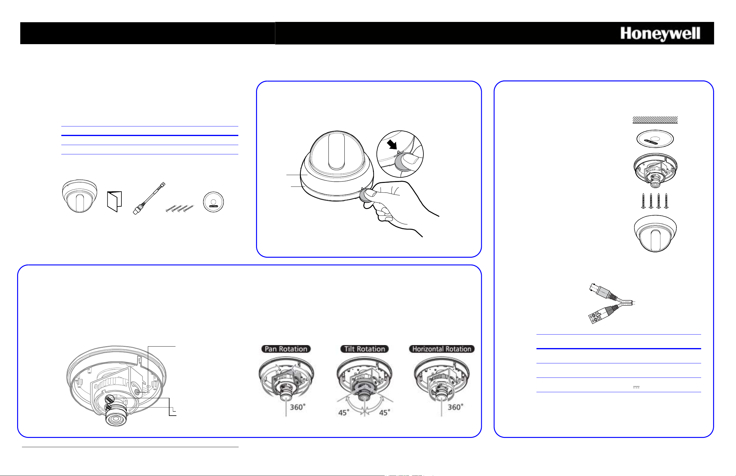
HD3U/X camera Owner’s
manual
Service
monitor
cable
Mounting
screws
Mounting
template
Ceiling
Mounting
template
Camera
base
Mounting
screws
Dome
cover
Power input
Video output
Legend:
1. Adjust the vertical angle
2. Adjust the horizontal angle.
3. Adjust the horizontal positon.
4. Focus (Far or Near)
5. Zoom (Tele or Wide)
Loosen these screws to
unlock the gimbal.
Fixed Dome Camera
Quick Install Guide
Document 800-05023 – Rev D – 02/10
1 Remove the Dome Cover
2 Mount the Camera
Thank you for purchasing a Honeywell Day/Night Ultra Wide Dynamic Fixed Dome
Camera. Before installing the camera, please verify your model and read this guide
carefully:
Model Signal format Lens
HD3U NTSC 2.8 to 10.5 mm Vari-focal Auto Iris lens
HD3UX PAL 2.8 to 10.5 mm Vari-focal Auto Iris lens
Unpack Everything
3 Adjust the Camera
Dome
cover
Camera
base
Before you can mount or adjust your HD3U/X, you must remove the dome cover.
Insert a coin or screwdriver in the slot on the dome cover, then twist to pry the dome
cover from the camera base.
The HD3U/X camera is designed to be surface mounted on a wall or ceiling.
1. Attach the mounting template to the
wall or ceiling.
2. Drill four holes according to the
mounting template, then insert
anchors (not supplied) into the drilled
holes.
3. Pull power and video cables through
to the connectors. See “Connect the
Wiring” (see below).
4. Use the four screws (supplied) to
attach the camera to the wall or
ceiling.
Note Leave the dome cover off until
you have adjusted the camera.
Connect the Wiring
To adjust the HD3U/X Camera:
1. Apply 12 VDC or 24 VAC power to the camera and monitor the video signal.
2. Loosen the screws that lock the gimbal assembly in place (see below).
3. Adjust the camera gimbal to the desired view.
4. Tighten the screws to lock the gimbal assembly in place.
Note Orient the camera as shown in “Adjusting the Lens Focus” to
maintain the correct picture orientation.
Document 800-05023 – Rev D – 02/10
Adjusting the Lens Focus
Lenses are pre-focused at the factory. In the unlikely event that the optical effect of
the dome cover causes a slight defocusing of the lens, hold the dome cover over the
lens to make a final adjustment.
Function Terminal
Color
Video
output
Power
input
The power connections are not polarity sensitive.
Use a 24 VAC ~ power source or a 12 VDC power source.
Yellow 1.0 Vp-p
Green 24 VAC (20V~28V) or 12 VDC (10V~15V),
Remarks
Max 3.8 W, 310 mA
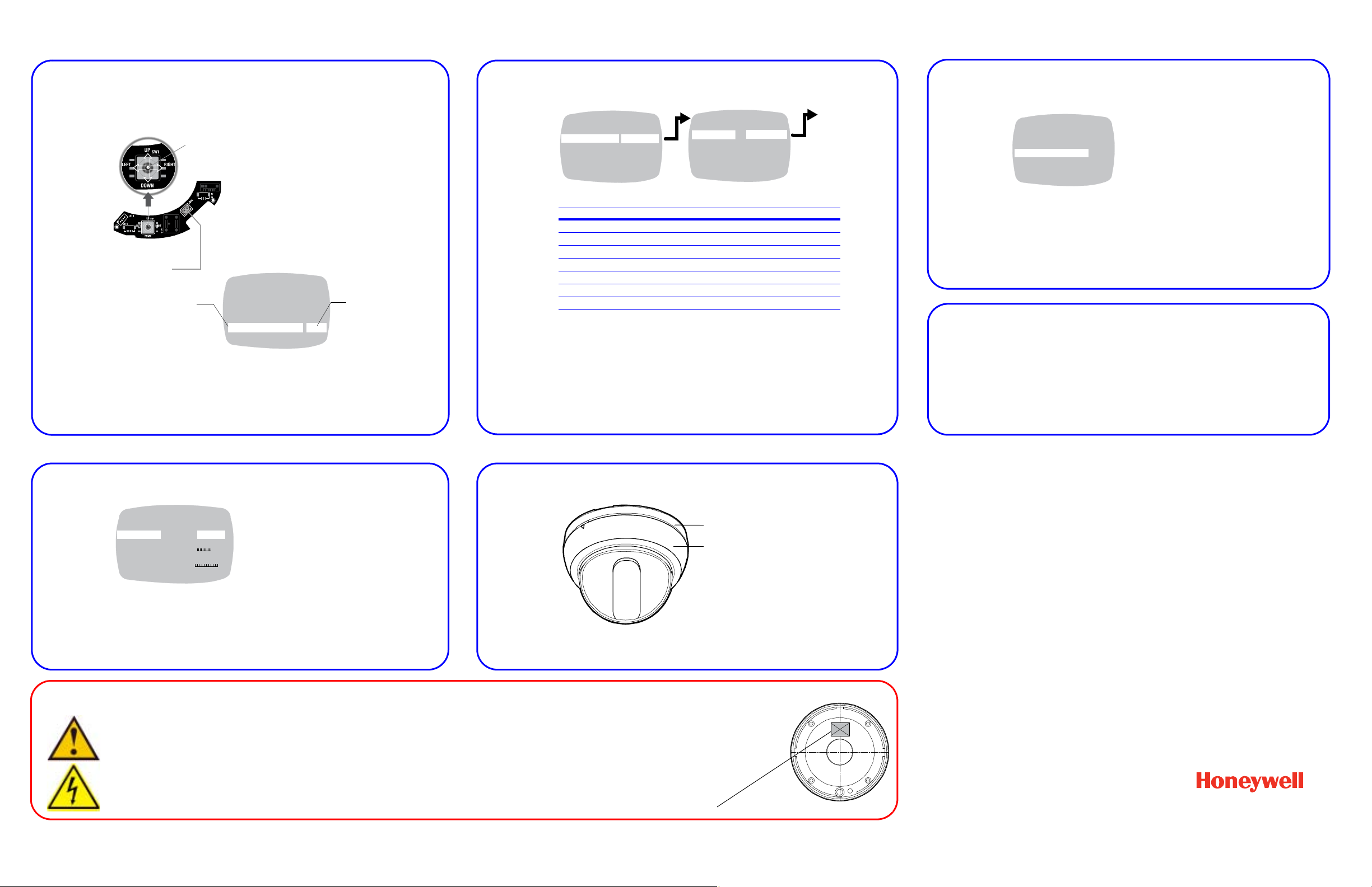
4 Operate Your Camera
Joystick (5 way) control
- Press down on the joystick in the center position and hold
two seconds to access the MAIN MENU.
- Press down again on the center position to select ENTER
and to enter a screen or to select a menu option.
,
,
“..” indicates submenus
To save your changes, select SAVE & EXIT, and then
ENTER. Your settings remain in effect when power is
turned off, then on again.
Select a menu, then
press ENTER to enter
the submenu.
Move the joystick
or
to change the status.
>
MENU
CAMERA SETUP ..
VIEWING ..
WDR PRESETS ..
DAY/NIGHT SETUP ..
VERSION INFO ..
RESTORE DEFAULTS <NO>
EXIT EXIT W/O SAVE.
Move horizontally to and between menus and
options
Move vertically to and between menus and options
Local video out
connection
Center
position
= ENTER
>
WDR PRESETS
>
MENU
CAMERA SETUP ..
VIEWING ..
WDR PRESETS .. INDOOR>
DAY/NIGHT SETUP ..
VERSION ..
RESTORE DEFAULTS
EXIT SAVE & EXIT
WDR PRESETS
PRESETS .. <CUSTOM.>
FLUORESCENT OFF
PREVIOUS PAGE
WDR Preset Area of Interest WDR Exposure
INDOOR Full scene Wide Highlights
LOADING DOCK Center scene Ultrawide Highlights
GAMING Full scene spot glare Medium Highlights
LICENSE PLATE Full scene spot glare Medium Shadows
OUTDOOR Full scene Ultrawide Highlights
ATM Center scene Ultrawide Shadows
LOBBY Center scene Wide Shadows
The Wide Dynamic (WDR) presets and the scenes for which they are optimized.
INDOOR
LOADING DOCK
GAMING
LICENSE PLATE
OUTDOOR
ATM
LOBBY
Note This setting is dependent on
the AGC setting.
On the DAY/NIGHT SETUP menu, select:
• DAY/NIGHT SETUP, then select either:
• AUTO (default) depending on the light
level, the camera automatically switches
from color to black and white, OR
• OFF the camera stays in color mode
regardless of the light level, OR
• B/W the camera stays in black and white
mode regardless of the light level
• *CLR BURST (color burst), then select either:
• ON (default) = B/W with color burst, OR
• OFF = B/W without color burst
>
MENU
CAMERA SETUP ..
VIEWING ..
WDR PRESETS .. INDOOR>
DAY/NIGHT SETUP ..
VERSION ..
RESTORE DEFAULTS
EXIT SAVE & EXIT
VIEWING
FLIP OFF
ID DISPLAY <OFF>
SHARPNESS NORMAL
BRIGHTNESS 110 80 130
RESOLUTION NORMAL
COLOR ADJ. 0 -8 8
PREVIOUS PAGE .
>
The VIEWING menu has the following controls:
• FLIP reverses the image horizontally on the
video monitor.
• ID DISPLAY opens the CAMERA ID SETUP
screen where you can add a CAMERA ID
(title) of up to 8 characters. You can also
select the position of the CAMERA ID on the
video monitor.
• SHARPNESS and RESOLUTION affect the
sharpness of the image.
• BRIGHTNESS adjusts the brightness of the
image.
• COLOR adjusts the color saturation.
Dome cover
Camera base
Camera Functions
5 Select the WDR Preset For Your Scene
6 Set the Day/Night Function
Note Certain video recorders require color carrier/burst to operate.
7 Set the AGC
The Automatic Gain Control is set by the chosen WDR preset. You can refine the
AGC setting in the AGC menu (MAIN MENU
This setting affects the day/night threshold. A higher AGC value results in the
camera switching from day to night mode at lower light levels. Adjust the level of
gain applied to the video signal in low light conditions.
➤ CAMERA SETUP ➤ AGC).
8 Set the Camera Image Properties
Important Safety Instructions
1. Read these instructions.
2. Keep these instructions.
3. Heed all warnings.
4. Follow all instructions.
5. Do not use this apparatus near water.
6. Clean only with a dry cloth.
7. Install in accordance with the manufacturer’s instructions.
8. Do not install near any heat sources such as radiators, heat registers, stoves,
or other apparatus (including amplifiers) that produce heat.
Honeywell Security Group (Head Office)
9 Install the Enclosure Cover
To install the dome cover, align the dome cover with the camera base and push until
it securely snaps into place.
9. Only use attachments/accessories specified by the manufacturer.
10. Unplug this apparatus during lightning storms or when unused for
long periods of time.
11. Refer all servicing to qualified personnel. Servicing is required when
the apparatus has been damaged in any way, such as power-supply
cord or plug is damaged, liquid has been spilled or objects have
fallen into the apparatus, the apparatus has been exposed to rain or
2700 Blankenbaker Pkwy, Suite 150
Louisville, KY 40299, USA
www.honeywellvideo.com
+1.800.796.2288
Honeywell Security Group Europe/South Africa
Aston Fields Road, Whitehouse Industrial Estate
Runcorn, Cheshire, WA7 3DL, UK
www.honeywell.com/security/uk
+44.01928.754028
Honeywell Security Group Caribbean/Latin America
9315 NW 112th Ave.
Miami, FL 33178, USA
www.honeywellvideo.com
+1.305.805.8188
Honeywell Security Group Pacific
Level 3, 2 Richardson Place
North Ryde, NSW 2113, Australia
www.honeywellsecurity.com.au
+61.2.9353.7000
Honeywell Security Group Asia
35F Tower A, City Center, 100 Zun Yi Road
Shanghai 200051, China
www.asia.security.honeywell.com
+86 21.5257.4568
Honeywell Security Group Middle East/N. Africa
Post Office Box 18530
LOB Building 08, Office 199
Jebel Ali, Dubai, United Arab Emirates
www.honeywell.com/security/me
+971.04.881.5506
moisture, does not operate normally, or has been dropped.
This product is CLASS 2 only.
The UL listing label is located on the back of the camera.
© 2010 Honeywell International Inc. All rights reserved. No part of this publication may be reproduced by any means without written permission from Honeywell Video Systems. The
information in this publication is believed to be accurate in all respects. However, Honeywell Video Systems cannot assume responsibility for any consequences resulting from the use
thereof. The information contained herein is subject to change without notice. Revisions or new editions to this publication may be issued to incorporate such changes.
Honeywell Security Group Northern Europe
Ampèrestraat 41
1446 TR Purmerend, The Netherlands
www.honeywell.com/security/nl
+31.299.410.200
Honeywell Security Group Deutschland
Johannes-Mauthe-Straße 14
D-72458 Albstadt, Germany
www.honeywell.com/security/de
+49.74 31.8 01.0
Honeywell Security Group France
Immeuble Lavoisier
Parc de Haute Technologie
3-7 rue Georges Besse
92160 Antony, France
www.honeywell.com/security/fr
+33.(0).1.40.96.20.50
Honeywell Security Group Italia SpA
Via della Resistenza 53/59
20090 Buccinasco
Milan, Italy
www.honeywell.com/security/it
+39.02.4888.051
Honeywell Security Group España
Mijancas 1. 3a planta
P.Ind. Las Mercedes
28022 Madrid, Spain
www.honeywell.com/security/es
+34.902.667.800
www.honeywellvideo.com
+1.800.796.CCTV (North America only)
HVSsupport@honeywell.com
Document 800-05023 – Rev D – 02/10
 Loading...