

Page 1
上海市水泉路88弄8号503室 电话:021-56356105 传真:021-56356109
HC900 Hybrid Controller
51-52-03-31
9/03
Page 1 of 36
Technical Overview
Overview
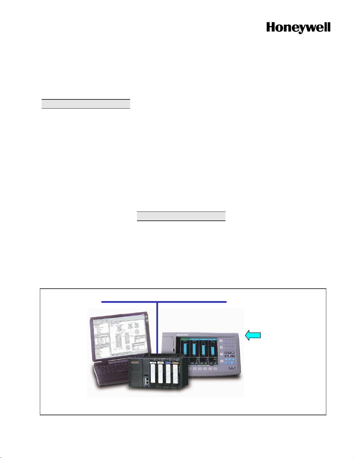
The Honeywell HC900 Hybrid
Controller is an advanced loop and
logic controller offering a modular
design sized to satisfy the control and
data acquisition needs of a wide range
of process equipment. When
combined with the optional,
performance rich 1042 or 559 Operator
Interfaces that fully integrate the
controller database, configuration and
setup time is minimized. This powerful
combination together with Honeywell's
performance proven control technology
provides users an ideal solution for
process control. Open Ethernet
connectivity also allows network
access using a variety of HMI/SCADA
software.
Easy-to-use Windows-based Hybrid
Control Designer software, operable
over Ethernet, an RS232 port or
modem connection, simplifies
controller and operator interface
configuration. It provides advanced
monitoring functions for debug, allows
run-mode configuration changes while
limiting process interruption, uploads
the complete, annotated graphic
controller and operator interface
configuration, plus supplies an array of
printouts for enhanced documentation.
The HC900 Controller provides
superior PID loop control and more
robust analog processing than most
logic controllers without compromising
logic performance. A separate, fast
scan cycle is available to execute a
rich assortment of logic and calculation
function blocks. Logic blocks may also
execute synchronous with analog
function blocks. These function blocks
may be fully integrated into a combined
analog and logic control strategy for
uncompromising control performance.
Feature Summary
• Compact size – 5.4 “(137mm) high
• Up to 32 loops of PID Control
• Up to 960 points with remote I/O
• Remote I/O Racks
• Up to 256 Isolated, Universal
Analog Inputs
Ethernet
Specification
• I/O Insert/Remove under power,
auto-configured
• LED on/off indicators on digital I/O
• Graphic Function Block
Configuration – up to 2000 blocks
• Boolean Logic programming
• Robust assortment of algorithms –
over 100
• Advanced Floating Point Math
Functions
• Fast updates – 27 ms logic, 0.5 sec
analog
• Open 10MB Ethernet interface
using Modbus/TCP protocol –
supports 5 concurrent host
connections
• Peer-to-peer communications via
Ethernet
• Extensive Alarm and Event
Monitoring
• E-mail alarm/event messaging on
priority
• 8 Ramp/Soak Setpoint
Programmers
• 2 Setpoint Schedulers with multiple
outputs
• 4 Sequencers with 16 Outputs each
• Stored recipes, SP profiles,
sequences, schedules
• Carbon Potential and RH Control
1042 OI
Hybrid
Control
Designer
Software
Figure 1—HC900 Hybrid Controller Overview
HC900 Hybrid Controller
Industrial Measurement and Control, 1100 Virginia Drive, Fort Washington, PA 19034
Printed in U.S.A. ■ © Copyright 2002 — Honeywell
· Furnaces
· Kilns
· Autoclaves
· Dryers
· Fermenters
· Water treatment
· Boilers
· Utility DAQ
· Pump stations
· Retorts
· Sterilizers
· Crystal Growing
· Extruders
· Pilot Operations
Page 2

51-52-03-31
上海市水泉路88弄8号503室 电话:021-56356105 传真:021-56356109
Page 2
HC900 Controller
The rack based HC900 Controller is
available in 3 rack sizes with 4, 8 or 12
I/O slots each to support a wide range
of requirements.
C50 CPU -For greater installation
flexibility the C50 CPU allows up to 4
additional remote racks to be
connected to a single controller (with
its local I/O rack) to reduce wiring and
installation cost. A variety of analog
and digital I/O modules are available to
support a total of 960 I/O points,
including up to 256 analog input points
and 64 analog output points per
controller.
C30 CPU -The C30 CPU supports a
single rack with 4, 8 or 12 I/O slots and
can accommodate up to 96 analog
inputs or 192 total I/O points.
A standard Ethernet communication
port on the C50 and C30 CPUs
provides open connectivity to PCs or
other supervisory interfaces and
supports peer data exchanges to other
controllers.
Inputs and Outputs - A variety of I/O
modules are available for selection in
creating a custom control solution.
These include:
8 point universal analog input cards:
Inputs may be mixed on a card and
may include multiple thermocouple
types, RTDs, ohms, voltage or
millivoltage types – all easily
assigned using the Hybrid Control
Designer configuration tool. High
point to point isolation simplifies
installation and saves the expense of
external isolation hardware.
4 point isolated analog output card:
Supports from 0 to 20mA each.
16 point digital input cards: Contact
closure type, DC voltage and AC
voltage types.
8 point AC or 16 point DC digital
output cards
8 point relay output card: four form C
type and four form A
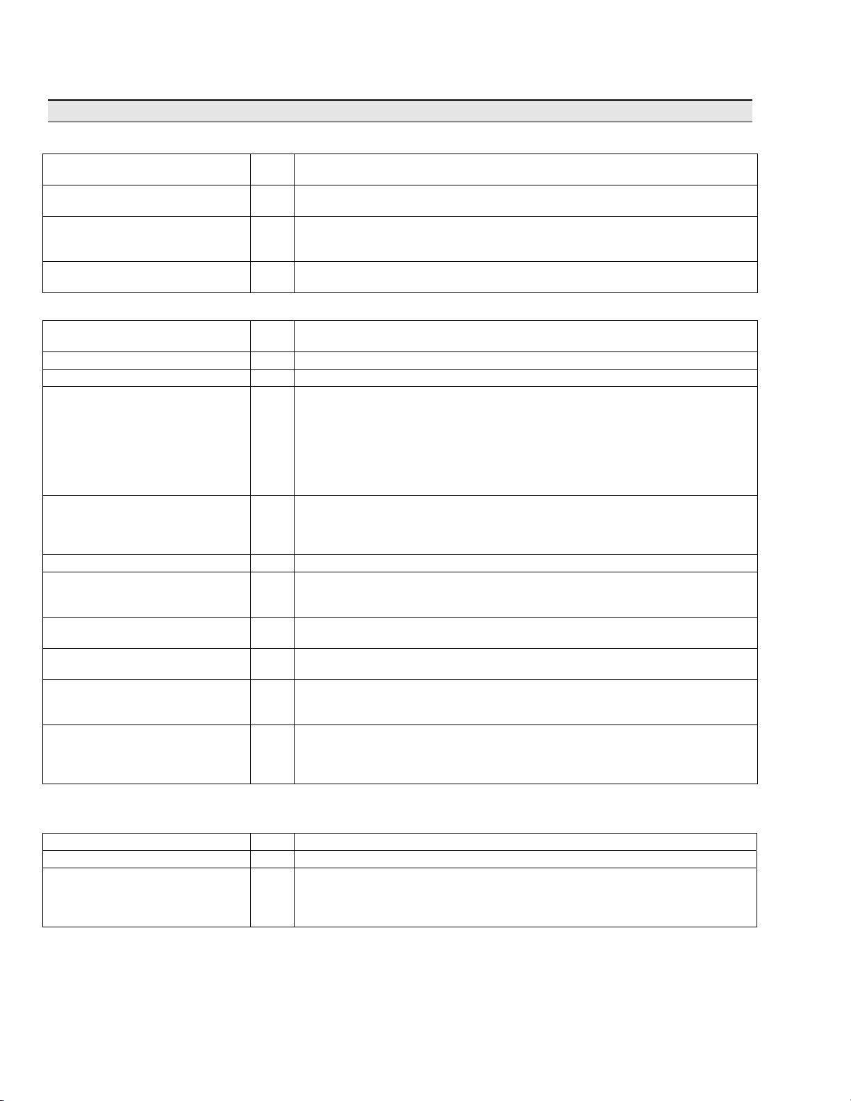
Input Type Point per Module Max. Points per C50/C30 Controller
Analog In 8 256/96
Analog Out 4 64/48
Digital In 16 960/192
Digital Out 8 AC or 16 DC 960/192
type relays.
Remote I/O- Up to 4 I/O racks may be
remotely mounted from the controller
via an Ethernet-private 10Base-T
connection at up to 300 meters (984
feet) between the controller and the
most remote rack using two Ethernet
hubs.
Insert & removal of I/O under power-
For ease of maintenance, the HC900
controller supports removing and
inserting I/O modules from the card
rack without removing power from
controller. Each card is sensed for
validity by the controller and autoconfigured on insertion.
Remote Terminal Panels - Optional
DIN rail mounted Remote Terminal
Panels (RTPs) are available for use
with pre-wired cables to reduce
installation time and labor expense.
Three types of RTPs are available:
analog inputs, relay outputs and other
I/O modules. Three cable lengths are
also available to match hardware to
installation variations. Analog input
RTPs include transmitter shunt
resistors and transmitter power
terminals with individual circuit fuses.
The RTP panels also switch field
power to allow module removal and
installation under controller power.
the
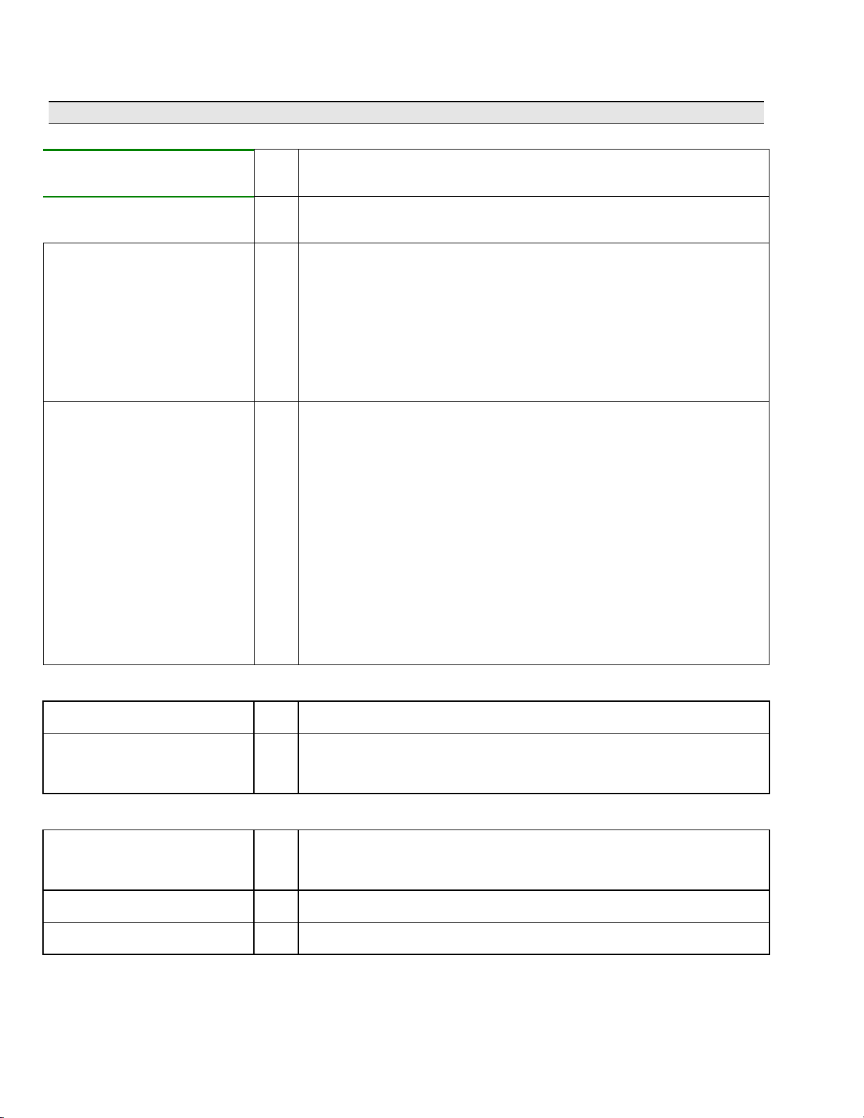
Function Blocks
Each HC900 Controller can support up
to 2000 analog or digital function
blocks. Each function block algorithm
may be used any number of times in a
control strategy unless specifically
identified with quantity limits. Of the
more than 100 function blocks
available, 12 block types have limits
imposed. These include:
C50
Control Loops – 32 8
Setpoint Programmers – 8 8
Setpoint Schedulers – 2 2
Sequencers – 4 4
Alternators – 6 6
Stages – 8 8
Ramps – 8 8
Hand/Off/Auto – 16 16
Device (Pump) Control – 16 16
Pushbuttons (4 PB’s/block) – 8 8
Sel switches (4-position) – 8 8
Position Proportional Output – 64 16
I/O Capacity
C30
User configurations are permanently
retained in flash memory in the
controller. In the event a PC
configuration file is lost or misplaced, it
can be easily reconstructed using the
upload function of the Hybrid Control
Designer configuration software or via
the 1042 and 559 OIs. Simply read the
configuration from the controller to
duplicate the original
exactly
configuration, including all text
descriptions and operator interface
display selections. In the event edits to
a controller’s configuration are required
after the unit is in operation, the on-line
download function of the HC900 Hybrid
Control Designer software allows
configuration changes while in the Run
mode, limiting process disturbances.
The dynamic control status is retained
in battery backed
controller. This function minimizes
process upsets during momentary
power interruptions and other
discontinuous operations.
Advanced control and
computational capability - A large
assortment of analog and digital
function blocks are available to solve
the most demanding control
requirements. Typical analog function
blocks include totalizers, free-form
math, average, mass flow, function
generator, periodic timers based on
real-time, carbon potential, RH, Dew
Point, signal selection
and many others. These blocks may
be configured to create control
schemes that precisely address the
needs of your process. Digital status
outputs are also provided on many of
the analog function blocks to facilitate
intelligent signal alarming and default
operation strategies. Typical logic
function blocks include AND, OR,
XOR, NOT, Latch, Flip-flop, On/Off
Delay and Resetable timers, Counters,
Free-form Boolean logic and more.
The execution of analog and digital
functions is seamlessly integrated into
a single control strategy in the
controller.
RAM memory in the
, comparison,
Page 3

Loop Control- The robust control
上海市水泉路88弄8号503室 电话:021-56356105 传真:021-56356109
loops of the HC900 Controller support
configurations from simple PID to
interactive cascade, ratio, duplex,
position proportioning and three
position step for motor positioning or
custom control strategies. Standard for
every control loop is auto-tuning using
Honeywell’s performance proven
Accutune II tuning algorithm. A
selectable "Fuzzy Logic" algorithm is
also provided for each loop to suppress
unwanted process setpoint overshoot.
A soft start feature allows output rate
limiting for protection of a process load
on startup or after power failure.
Sequencers - The HC900 controller
supports up to four sequencer function
blocks, greatly enhancing configuration
of sequence operations. Each
sequencer supports up to 16 digital
outputs that may be either on or off in
each of 50 states e.g. PURGE, FILL,
HEAT, etc. The sequencer may have
up to 64 sequential steps that activate
within the states of the process. Steps
of the sequencer may be configured to
advance based on time, on event (2
per step), or a manual advance. A
separate jog function is also provided.
The function can also configure an
analog output on a step basis. The
operational sequence for the steps is
retained in a separate sequence file in
the memory of the controller that
may
be selected on-demand through a user
interface or via a recipe. Up to 20
sequences may be stored.
Set Point Programming - Up to 8
independent set point programmers,
each with an auxiliary soak output may
be configured. A pool of up to 99
profiles, each with up to 50 segments
may be stored in controller memory for
user selection. Each programmer may
have up to 16 event outputs for
integration with the sequence control
functions. Features such as
guaranteed soak, jog to a segment and
looping are also provided.
Setpoint Scheduling - Up to 2
independent setpoint scheduler
functions may be configured. The
scheduler function provides up to 8
ramp and soak outputs plus up to 8
soak only outputs that operate on a
common time base. The scheduler
also supports up to 16 event digital
outputs. Soak guarantee, jog to a
segment and nested looping features
are also provided. Applications include
multi-zone diffusion furnaces, CVD
furnaces, and environmental
chambers. Up to 20 schedules can be
stored in the controller for user
selection.
51-52-03-31
Logic - Logic programming may be
used to implement more robust and
higher speed logic functions in the
controller. The fast scan program
executes all inputs, outputs and
function blocks as fast as 27
milliseconds. The fast scan instruction
set includes 2, 4 and 8 input logic
blocks with selectable input inversion
plus timers, triggers, latches, counters,
timers, math and other supporting
functions. A Sequencer function is also
included with functionality beyond
typical drum sequencers.
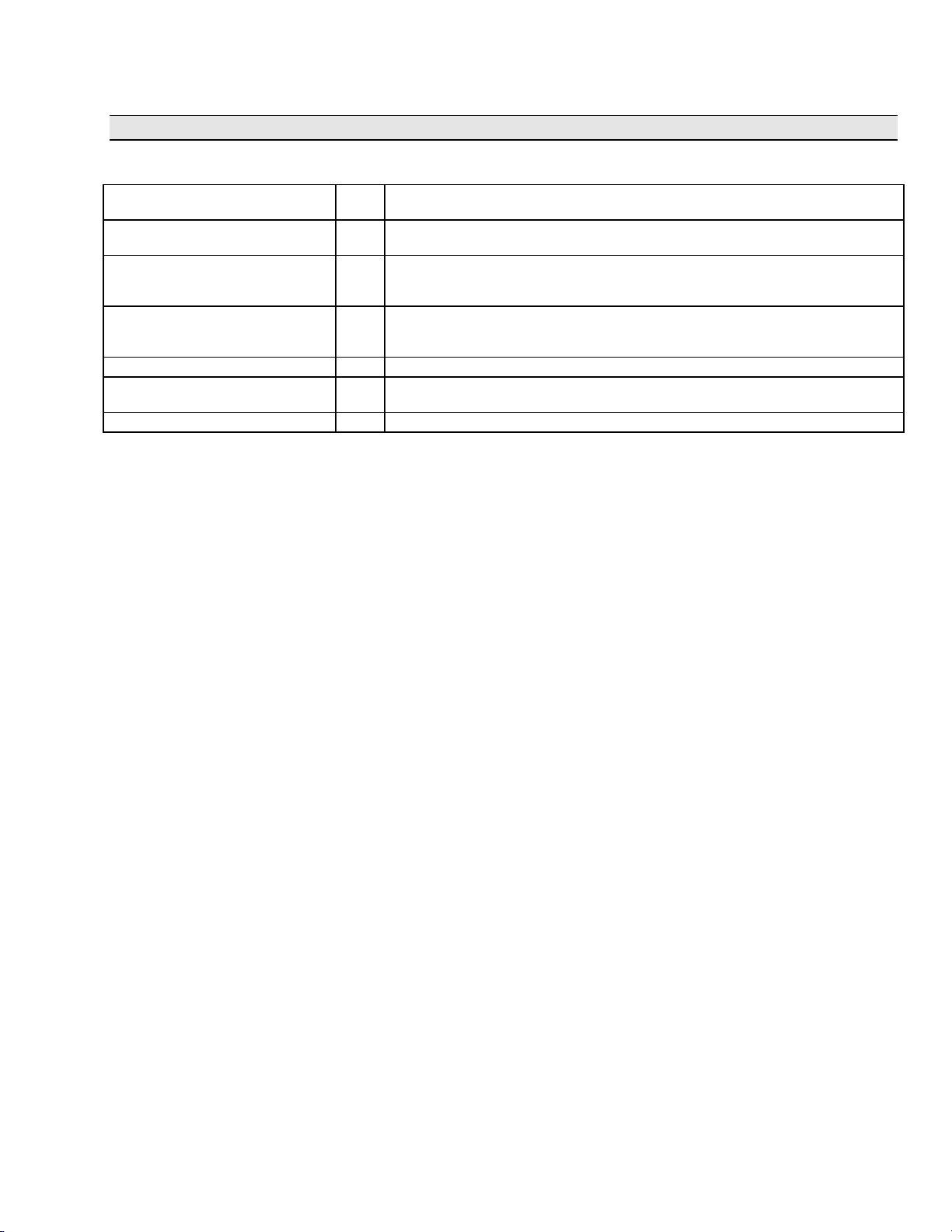
Sequence Control
Outputs
Step State State
Name
1 1 PURGE 1 0 0 1 0 1 0 0 0 1 1 0 1 0 1 1
2 5 AGITATE 1 0 1 0 1 0 1 0 0 1 1 0 1 0 1 1
3 2 FEED B 0 1 1 1 1 0 1 0 0 1 1 0 1 0 1 1
4 3 MIX 1 1 1 1 1 1 1 1 1 1 1 0 1 0 1 1
5 8 PREHEAT 0 0 0 1 0 0 1 0 0 1 1 0 1 0 1 1
1 2 3 4 5 6 7 8 9 10 11 12 13 14 15 16
↓
64 50 STOP 0 0 0 0 0 0 0 0 0 0 0 0 0 0 0 1
Seg Ramp/
Soak
Value
1 Ramp 100 20 0.0 OFF 100110000000000
2 Ramp 500 30 1.1 OFF 100100100000000
3 Soak 1300 90 1.1 ON 101110100000000
4 Ramp 1300 50 1.1 OFF 100100100000000
5 Soak 100 0.1 0.0 OFF 00000000100000
Recipes – Up to 50 recipes are stored
in the controller. Recipes consist of up
to 50 analog and digital Variables
assigned within the configuration. This
allows Variables representing setpoint
profile, setpoint schedule, or sequencer
numbers and/or other Variables for
associated loop setpoints, bias values,
alarm setpoints, limits, setpoints to
external controllers, digital states,
tuning constants, etc. to be part of a
recipe. Recipes are selected by recipe
tag name and descriptor from the
HC900 Operator Interface or via a
Recipe Selection block with a recipe #
input.
Setpoint Profile Table
SP
Time/
Rate
Aux
Out
Tag Descriptor
PROFNUM Profile Number 2
BIAS2 TempBias–Zone2 12
BIAS3 TempBias–Zone3 18
Guar
Events
Hold
Recipe: P1023-F7
TYPE 1023 HARDEN
Variable
Up to 50 Variables
Value
↓
HIALMSP1 F1 Hi Temp Alarm 1280
Page 3
Page 4

51-52-03-31
上海市水泉路88弄8号503室 电话:021-56356105 传真:021-56356109
Page 4
HC900 Function Block Types
I/OBlocks (F=Fast Scan Rate, N=Normal Rate)
Analog Input N
Analog Output N
Digital Input (1) F,N
Universal Analog Input, with table selection of input type (See Table 3 )
Filter – 1
Bias – Input value adjust for calibration correction
Burnout – Off, Upscale, Downscale, Default Value
Warn Output – activates if thermocouple resistance > 100 ohms.
Input Disable –digital input when ON disables input, sets output to a defined
default
Regulated analog output current
Input scaling in Engineering Units, Output scaling within 0 and 20 mA
Slew rate definable, Fail output pin is ON when output fail sensed, Failsafe
definable
Provides the digital status of a digital input point. The output status may be
inverted. Both fast logic (27 ms) and normal logic (500ms analog rate) blocks
available. Fail Output – activates on failed input channel or failed remote rack
communications.
st
order lag, 0 to 120 seconds
Digital Input (Up to 8 inputs) F,N
Digital Output (1) F,N
Digital Output (Up to 8 outputs) F,N
Time Proportioning Output
(applied to any PID output)
Position Proportional Output
C50 CPU up to 64 per controller
C30 CPU up to 16 per controller
N
N
Provides the digital status of the first or last 8 digital inputs of a 16 point input
card. The output status may be inverted. Both fast logic (27 ms) and normal logic
(500ms analog rate) blocks available. Fail Output – activates on failed input
channel or failed remote rack communications
Directs a digital status to a physical logic output. Output status may be inverted.
Both fast logic (27 ms) and normal logic (500ms sec analog rate) blocks
available. Fail Output – activates on output failure or failed remote rack
communications.
Directs 8 digital statuses to 8 physical logic outputs of an 8 point output card or
to the first or last 8 physical logic outputs of a 16 point output card. Output status
may be inverted. Both fast logic (27 ms) and normal logic (500ms analog rate)
blocks available. Fail Output – activates on any one of 8 outputs with failed
output or failed remote rack communications.
Proportions the amount ON time and OFF time of a digital output.
Input scaling in engineering units
Cycle time—2 second to 120 seconds
Output minimum ON and OFF time—0 seconds to 15 seconds
A combination Input and Output function block that includes feedback input
configuration and increase/decrease digital output configuration.
Positions actuators with slidewire, current or voltage position feedback sensors.
Provides outputs for actuator position (0 to 100%), motor fail, and feedback fail –
automatically defaults to 3-position step on feedback fail.
Input scaling in engineering units
Actuator speeds from 12 to 300 seconds
Output limits – adjustable (between 0 and 100%)
Deadband – adjustable (0.5 to 5%)
Feedback filter – adjustable (0 to 3 sec.)
Feedback input types:
Slidewire 100 to 250 ohms ( requires AI card 900A01-0002)
Slidewire 250 to 1000 ohms (requires AI card 900A01-0002)
mA - 4 to 20mA
mA - 0 to 20mA
Voltage - 0 to 1V
Voltage - 0 to 5V
Feedback calibration – HC Designer, 1042 or 559 Operator Interfaces
Automatic, Semi-automatic, and Hand methods supported.
Page 5

HC900 Function Block Types (continued)
上海市水泉路88弄8号503室 电话:021-56356105 传真:021-56356109
Control Loop Function Blocks (F=Fast Scan Rate, N=Normal Rate)
51-52-03-31
Page 5
PID
C50 CPU - up to 32 per controller
C30 CPU – up to 8 per controller
PID for Carbon Potential
C50 CPU - up to 32 per controller
C30 CPU – up to 8 per controller
(displaces PID)
PID with 3 Position Step Output N Motor position control without position sensing. Standard PID features with
ON/OFF Control (32 standard)
(displaces PID)
Loop Switch Inputs N Digital interface to control loops to initiate autotuning, change control action,
Loop Mode Selection N Digital interface to control loops to select automatic or manual modes and/or
Mode Decoder (Mode Flags) N Decodes control loop mode status into a set of discrete (Boolean or digital) mode
Write Tuning Constants N
PID algorithm includes:
N
N A combined carbon potential calculation and PID algorithm for controlling the
N ON/OFF control algorithm with selectable hysteresis
• Accutune II auto-tuning
• PID A (normal) or PID B (only integral response to SP change) operation,
DUPA and DUPB operation which switches tuning constants for heat/cool
applications
• Two sets of PID constants selectable via program control. Choice of Gain or
Proportional Band entry and Integral time or Repeats/minute entry
• Setpoints—Two setpoint values or one value and one remote setpoint
• Setpoint tracking – Local SP tracks PV or RSP on a RSP to LSP change
• Setpoint limits, output limits, SP rate of change
• Soft start
with output tracking)
• Ratio and Local/Remote Bias selections for Ratio control applications
• Feedforward input (scaled in % of output)
• Back calculation output for Cascade operation (supplied to primary loop)
• Output tracking to track a remote input (for backup applications)
• Remote A/M, R/L mode switching and mode status outputs
• Function block access to tuning constants for gain scheduling
• Alarms—Two outputs with up to two high, low, or dev band conditions each
Inputs: PV, remote setpoint, feedforward, output track and track command, ratio,
Outputs: Control output, working setpoint, alarm status (2), Autotune indication,
carbon potential of furnace atmospheres using a zirconia probe input and
temperature input. Local/remote %CO adjustment, probe manufacturer selection
(4 selections), anti-sooting protection, dewpoint calculation output, and furnace
factor adjustment is supported; probe burn-off configurable.
addition of hysteresis (in %) and full stroke time (in sec.) entries for motor.
force bumpless transfer, select tuning set #1 and select tuning set #2. Connects
to PID (all) and ON/OFF block switch input.
local or remote setpoint. Connects to all control loop types.
flags.
Automatically changes the GAIN, RATE, and RESET parameters of an internal
PID loop without operator interaction. A digital input controls changes.
for output rate limiting on startup or after power fail (not available
bias, switch block connection, mode switch block connection, and back
calculations
mode status
and selectable fuzzy logic overshoot suppression
Auto-Manual Bias (32 standard,
displaces PID) (for Boiler Control
applications)
N
Allows a manually adjusted output to be maintained on transfer to automatic by
applying bias to the input signal (from a Steam master to adjust participation of
boiler). Bias value is maintained as output value tracks input value changes.
Consumes 1 loop.
Page 6

51-52-03-31
上海市水泉路88弄8号503室 电话:021-56356105 传真:021-56356109
Page 6
HC900 Function Block Types (continued)
Setpoint Programmer and Recipe Function Blocks (F=Fast Scan Rate, N=Normal Rate)
Setpoint Programmer (8
maximum)
Setpoint Program Events (up to 16
events per block)
Setpoint Program Synchronizer N Used to synchronize the operation of two setpoint programs given the Run, Hold
Recipe Block F,N Used to initiate loading of recipe values into a chosen set of controller variables
N Produces a setpoint output for a time-based ramp/soak profile that is loaded into
the block. (See Setpoint Programming description for profile details.)
Inputs:
Process Variables, up to 3, to establish setpoint guarantee operation based on
a deviation band from setpoint. Profile Number (for autoload of a profile # for
next run), New Starting Segment (uses a Set input to enter a new segment
number).
Digital Inputs:
Enable (allows programmer to be operated), Set (to load a program or new
start segment), Start, Hold, Restart (from power failure, can allow slower ramp
up to previous SP to protect product), Reset, Advance, Jog (to a specified
segment), and Guarantee Hold (to synchronize with another programmer).
Outputs:
Setpoint value, segment number, program number, time remaining in segment,
time elapsed in segment, program elapsed time.
Digital Outputs:
Status (Ready, Running, Hold, Stopped), synchronize hold state, program
state
N Provides up to 16 digital status outputs that may be ON or OFF on a per
segment basis. Inputs include program number, segment number, and program
state (READY, RUN, HOLD, GHOLD, or STOP) from setpoint program block
from program state output.
and Reset signals from each program.
based on a recipe number. Inputs include recipe number and load command,
allowing remote recipe selection.
Setpoint Scheduler Function Blocks (F=Fast Scan Rate, N=Normal Rate)
Setpoint Scheduler (2 maximum)
State Switch Block N Provides digital switch status inputs to the Scheduler block for Run, Hold, Reset,
State Flags Block N Accepts status output from the Scheduler block and provides digital output
Setpoint Scheduler Auxiliary
Output Block
Event Decoder N Provides up to 16 digital outputs that may be ON or OFF on a per segment
N Produces up to 8 ramp or soak setpoint outputs on a common single time base.
(See Scheduler description for details.)
Inputs:
Process variables, up to 8, to establish setpoint guarantee operation based on
deviation from setpoint. Schedule number is used for automatic schedule
loading and starting segment number allows first segment selection.
Digital inputs:
Dedicated input for connection to State Switch block output.
Outputs:
Up to 8 setpoint values, segment number, schedule number, time remaining in
segment, time elapsed in segment, schedule elapsed time.
Digital Outputs:
Dedicated output for connection to State Flags block input.
Ghold, Advance and Jog.
signals for Run, Hold, Ghold, Ready and Stop.
N Provides up to 8 additional analog setpoint (soak only) values for each segment
of the schedule.
Inputs: Up to 8 process variables used for display.
basis.
Page 7

51-52-03-31
上海市水泉路88弄8号503室 电话:021-56356105 传真:021-56356109
Page 7
HC900 Function Block Types (continued)
Auxiliary Control Function Blocks
Lead Lag Signal Conditioner N Modifies an analog input value to include lead and lag time constants when a
Function Generator N Generates an output characteristic curve based on up to 11 configurable
High/Low Limiter F,N Limits an analog variable between high and low limit values. Provides separate
Rate (Velocity) Limiter N Limits the rate at which an analog variable can change when a logic input is ON.
Rate of Change N Provides an output value representing the rate of change value of the input in
Read Constant F,N Provides a read access to internal static parameters of selected blocks by Block
Write Constant F,N Provides write access to internal static parameters of selected blocks by Block
Write Variable F,N Provides a write of a value to a selected analog or digital Variable number based
Track and Hold N Allows updating or holding the value of an analog input based on the state of a
BCD Translator F,N Accepts up to 8 digital inputs in sequence and interprets the ON/OFF status of
Digital Encoder N A 16 input block whose output is the decimal value of the number of ON inputs.
(F=Fast Scan Rate, N=Normal Rate)
digital input is true.
Lead time constant = 0 minutes to 99 minutes
Lag time constant = 0 minutes to 99 minutes
“breakpoints” for input and output values.
digital status outputs when high or low limit values are exceeded.
Provides independent increasing and decreasing rate of change limit values.
Separate digital status outputs indicate when high or low rate limits are active.
units per minute. Output value is positive for increasing input values and
negative for decreasing input values. Two setpoint values and digital outputs are
provided to indicate excess increasing or decreasing rates of change or
insufficient increasing or decreasing rates of change.
number and parameter index number.
number and parameter index number.
on the ON state of a digital input.
digital input.
the first 4 inputs as a BCD value between 0 and 9, and the second 4 digits as a
value between 10 and 90.
Specific Application Principal Blocks (F=Fast Scan Rate, N=Normal Rate)
Device Control (16 maximum)
(for Pump Control)
Stage (8 maximum) N Accepts one or two analog variables and compares the values to high and low
Ramp (8 Maximum) N Accepts an analog variable and re-scales the value to new, user specified units.
Alternator (6 maximum) N The alternator accepts up to 16 digital inputs and, on a one for one basis, turns
N Provides device control (pumps, etc) including Start, Stop, Feedback Delay times
along with feedback confirmation and failure check.
setpoints for each of 4 stages per block. Outputs are digital signals that remain
ON after exceeding one setpoint until exceeding the second setpoint value for
the specific stage.
Up to 4 re-scale calculations may be configured per block. The re-scale
calculation that is currently active is controlled by digital inputs to the block.
Digital inputs may also be used to force the output to a high or low limit value.
on up to 16 digital outputs as determined by a user specified alternating
sequence. Alternator sequences include:
Direct – Inputs are mapped to specific outputs.
Rotary – Outputs are managed on a Last ON/ First Off (LOFO) basis and the
mapped sequence indexes by one each time all of the outputs are off.
FOFO – First On, First Off alternates the outputs based on the sequence in
which the outputs were turned on. The first output to turn on is moved to the end
of the list once it turns off.
Fixed – The output sequence follows a user specified mapping sequence. A
manual advance causes the mapping sequence to index by one when enabled.
Both “make-before –break” and “break -before –make” selections are available
for the block with user specified time delays for output changes.
Page 8
51-52-03-31
上海市水泉路88弄8号503室 电话:021-56356105 传真:021-56356109
Page 8
HC900 Function Block Types (continued)
Signal Selector Function Blocks (F=Fast Scan Rate, N=Normal Rate)
High Selector/Low Selector F,N Provides the highest (high select) or lowest (low select) of two analog input
Switch N Output switches between two analog input values based on the status of a digital
Bumpless Analog Transfer N Output switches between two analog input values based on the status of a digital
Rotary Switch N Single output is selected from up to 8 analog values based on the numerical
Calculation Function Blocks (F=Fast Scan Rate, N=Normal Rate)
Compare F,N Compares one analog variable to a second analog variable and generates
Absolute Value F,N Provides an absolute value output for a single analog variable input.
Square Root N Output is the square root of a single analog variable input.
Mass Flow N Calculates the mass flow of gases when measuring flow using an orifice plate.
Minimum – Maximum – Average –
Sum
Negate F,N Accepts a single analog variable input and negates the output.
Totalize N Integrates an analog variable using a specified rate. Rate may be in units per
Deviation Compare N Compares up to 6 analog variables to deviation limits set around a 7th variable. If
Relative Humidity N Calculates the relative humidity using wet bulb, dry bulb, and atmospheric
Dewpoint (12 maximum) N A dewpoint PV is supplied to a PID function block for dewpoint control. Used in
Continuous Average N Provides the average value of a single analog parameter for a user-specified
variables.
input.
input. When switched, output ramps to the new value at a specified rate. A rate
value is available for each direction.
value of a select input (1 to 8).
separate digital outputs to indicate greater than, equal, or less than status.
Output = Kg * sqrt((Kx * X + Bx) (Ky * Y + By)/(Kz * Z + Bz))
with inputs X = differential pressure
Y = pressure, and
Z = temperature.
A low flow cut-off feature provides a user-specified drop-off value below which
the output goes to zero.
N Accepts inputs from up to 6 analog variables and outputs analog variables
representing the highest value, lowest value, average value, sum, and standard
deviation. Removes bad inputs and provides an alarm output for deviations of
any variable outside user-specified standard deviation.
minute, hour, or day. A preset is provided to indicate when a specific quantity
has been accumulated. Separate enable and reset inputs are provided.
any variable is outside the limits, a digital signal is provided.
pressure inputs. Output may be in degrees Fahrenheit or Celsius.
conjunction with other blocks including a PID to generate more elaborate control
strategies than that provided by the carbon potential function block.
time period, plus the running average within the time period. Average value is
updated at the end of each sample period. Time periods to 1440.0 minutes are
supported. A hold input allows excluding samples from the average when active.
Math Function Blocks
Scale and Bias F,N Output = (K * X) + b with single analog variable input X.
Two and Four Input Math F,N Executes +, – or * on two or four analog variable inputs, / on two inputs.
Free Form Math N Calculates the result of a user-specified equation with double precision. The
(F=Fast Scan Rate, N=Normal Rate)
block accepts up to 8 input signals (including Constants or Variables). Operators
include: +, -, , /, ^, and multiple levels of parentheses. Functions include:
absolute value, exp, ln, Log, neg, sqrt. Example: a*(sqrt(b+c))+d
Page 9

51-52-03-31
上海市水泉路88弄8号503室 电话:021-56356105 传真:021-56356109
Page 9
HC900 Function Block Types (continued)
Logic Function Blocks (F=Fast Logic Rate, N=Normal Rate)
AND, OR, XOR (2 inputs)
Boolean logic blocks
AND, OR (4 and 8 inputs)
Boolean logic blocks
NOT (Complement) F,N Inverts a logic input status.
Latch F,N Provides a digital output that turns ON when a digital input turns ON and remains
Edge Detection Element
(One-shot) [Trigger]
Toggle (Flip-Flop) F,N Provides an ON state output when a digital input goes from OFF to ON and the
Free Form Logic F, N Reads eight digital inputs and calculates the output based on specified Boolean
Pushbutton F, N Provides a one-shot output based on an OFF to ON change of an operator
Four Selector Switch N Provides up to 16 digital outputs in groups of four outputs each. Only one output
Sequencer (4 maximum) (Fast
logic scan only)
Hand/Off/Auto (16 maximum) N Provides Hand-Off-Automatic outputs based on digital inputs emulating a
Counters/Timers Function Blocks
Resettable Timer F, N Provides a timing function based on an enable input. Elapsed time value is
Periodic Timer N Provides an ON state output for one controller scan cycle based on a specified
Up/Down Counter F, N Counts the number of raising edge logic transitions on the input to the block up
ON-Delay Timer F, N An OFF to ON change of the digital input is delayed on the block output by a
F,N Provides a digital status output based on the digital status of two digital inputs for
logic AND, OR, or XOR (exclusive OR) operations. Input status of each input
may be inverted.
F,N Provides a digital status output based on the digital status of four or eight digital
inputs for logic AND or OR operations. Input status of each input may be
inverted.
ON (latched) after the input goes OFF until an unlatch input turns ON.
F,N Provides an ON state of its output for one controller scan when a digital input
goes from OFF to ON.
previous state of the output was OFF, and an OFF state output when the digital
input goes from OFF to ON and the previous state of the output was ON. A
reset input holds the output OFF when the digital input is ON or active high.
logic functions (e.g., AND, OR, NOT, etc.) and multiple levels of parentheses.
Example: (A*B)+C
interface key action. Supports four pushbuttons per block.
from each group may be ON at a time and when selected automatically turns
other outputs OFF. Simulates 4-position panel selector switches.
F, N The sequencer function block controls the output statuses of up to 16 digital
outputs and one auxiliary analog output. Each combination of outputs
represents a “State” of the sequence such as Heat, Mix, or Cool, for example.
The function block supports up to 50 states.
The sequencer contains up to 64 steps. Each step enables a State, allowing for
a State to be designated for several steps.
Each State supports two digital events as inputs that can designate the end of
the associated step.
Time in seconds or minutes, a manual advance, or a digital event can be used to
terminate a sequencer step and cause the sequence to advance.
A pool of 20 sequences, up to 64 steps each, may be stored in controller
memory for quick recall and assignment to any of the 4 sequencers.
standard H-O-A panel switch
(F=Fast Logic Rate, N=Normal Rate)
provided as an output. A Preset value allows settings from 1 second to 999999
seconds. A digital output is ON when time value is equal to the preset. An
up/down digital input is provided to allow reverse timing from the preset value. A
pre-load value allows initiating the timer to a non-zero starting time.
time period using the controller real-time clock. Periods may be monthly, weekly,
daily, or time period in a day.
to a preset value. When the preset value is reached a logic output is enabled. A
reset input resets the block. Value may be set to increase to the preset value or
decrease from the preset value (1–99999).
user-specified time (0.1 seconds to 999.9 seconds).
OFF-Delay Timer F, N An ON to OFF change of the digital input is delayed on the block output by a
user-specified time (0.1 seconds to 999.9 seconds).
Page 10
51-52-03-31
上海市水泉路88弄8号503室 电话:021-56356105 传真:021-56356109
Page 10
HC900 Function Block Types (continued)
Alarm and Signal Monitoring Blocks (F=Fast Scan Rate, N=Normal Rate)
High Monitor F, N Accepts two analog values and provides a digital status output if the first input is
Low Monitor F, N Accepts two analog values and provides a digital status output if the first input is
Analog Alarm N The analog alarm block accepts an analog signal as a process variable and
System Monitor Block
(1 block for normal scan and 1
block for fast logic scan) – (do not
count against the maximum block
count)
F, N Provides system and start-up status outputs including:
higher than the second input. A hysteresis adjustment is provided to prevent
output cycling.
lower than the second input. A hysteresis adjustment is provided to prevent
output cycling.
compares it to a user-entered limit value (setpoint) to determine an alarm
condition. The setpoint may be entered by the user or be another analog signal
in the controller. Alarm actions may be high, low or high deviation, low deviation
or band deviation. For deviation alarming, a second analog signal provides the
reference and setpoints represent deviation from the reference. The alarm output
may be inverted to create normally active digital output. A user selection for
latching until acknowledged or automatically reset is provided. A user-specified
hysteresis value in the engineering units of the process variable is provided. An
on-delay time value up to 240 seconds is available to prevent momentary alarm
actions. A digital reset input is available to disable alarm actions.
• Program scan cycle time
• Newstart pulse (ON for one scan cycle after a “cold” start (reset))
• Restart pulse (to activate a custom control action on power-up after power
loss)
• Two common alarm outputs - Active Unacknowledged (ON when at least one
alarm not ack’d), Active alarm (ON when at least one alarm is active), for
assignment to digital outputs
• Time off (the time that power has been off previous to restart)
• Low Battery (alert to change battery without power shutdown)
• Hardware OK (ON when all hardware including remote racks are OK)
• Hi Temp (Cold Junction temperature exceeds limits on a rack)
• Bad Block
• Master Fail
• Locked (controller toggle switch is in Run/Locked or Program position)
• DS Limit (OI data storage has reached its alarm limit)
Alarm, Signal, and System Monitoring Blocks (continued) (F=Fast Scan Rate, N=Normal Rate)
IO Rack Monitor– (do not count
against the maximum block count)
Alarm Group (Up to 20 blocks) –
(do not count against the
maximum block count)
N One monitor block per rack, 5 racks maximum (C50 CPU). Provides I/O module
fault status
N Supports acknowledgement of a group of up to 12 alarms using a controller
digital signal to block, internal or external (for remote acknowledge). Each alarm
group consists of up to 12 alarms. Outputs include Unacknowledged alarm and
Active alarm states. The 20 blocks support up to 240 alarms.
Communications Blocks (Peer to Peer) (F=Fast Scan Rate, N=Normal Rate)
PDE (Peer Data Exchange)
Control
PDE Read N Expands Read access for designated HC900 peer to an additional 16
PDE Write N Expands Writes to designated HC900 peer by an additional 8 parameters, each
N Interfaces to one HC900 peer device, accessed by controller name, supporting 8
parameter read requests and 4 event-triggered writes. Outputs may be given tag
names for use in configuration strategy. Update rate can be configured from 500
ms to 5 sec.
parameters.
triggered on event.
Page 11
51-52-03-31
上海市水泉路88弄8号503室 电话:021-56356105 传真:021-56356109
Page 11
HC900 Function Block Types (continued)
Other Diagram Items (F=Fast Scan Rate, N=Normal Rate)
Analog Variable F, N Connects to a function block’s inputs and can be changed from the operator
interface or via serial communications addressing.
Digital Variable F, N Connects to a function block’s inputs and can be changed from the operator
interface or via serial communications addressing.
T (Text) F, N Allows descriptive data to annotate a specific area of a function block diagram to
be entered. Four font sizes, four colors, bold/italics/underline supported. Text
may be entered multi-line.
Soft Wire F, N For reference only. Soft-wiring method is to double click on a block pin and then
clicks on a destination pin to complete soft-wire (or click to change direction en
route to destination pin).
Connector F, N Connects tagged signals to function block inputs.
Signal Tag F, N Allows a name to be assigned to a wire and accessed by the operator interface
or via serial communications.
Numeric Constant F, N A user-specified constant value that can be connected to function block inputs.
Page 12

51-52-03-31
上海市水泉路88弄8号503室 电话:021-56356105 传真:021-56356109
Page 12
Alarms and Events
Alarms
An alarm may be assigned to any
digital tag applied to a digital status
output of a function block. Each control
loop has two alarm status outputs,
each corresponding to alarm setpoints
of various types (e.g. PV HI, Dev
High/Low, etc.). There are specialized
alarm blocks for analog alarms with
hysteresis adjustment. An expanded
function analog alarm block also
provides selection of alarm type, an on
delay, selective latching, and a disable
input to control when the alarm is
active.
Alarm assignment is initiated by
adding the digital “alarm” tags to an
alarm group from a tag list. Alarm
group blocks allow alarm partitioning
into groups of 12 alarms. The 20
alarm group blocks allow up to 240
alarms to be defined. Each group
may be assigned an alarm
acknowledge function which permits
external, panel acknowledge via a
digital input or via a serial
communications write to an internal
Variable. Alarm groups may also be
assigned to displays for the 1042 and
559 Operator Interfaces (OI).
Alarms can be assigned a priority (one
of 4 levels - Low, Medium, High,
Emergency) for use in routing a topic
and 48 character alarm message
electronically to any of three locations
via the e-mail of alarms feature, if
selected for an individual alarm. Alarm
detection may also be on an off-to-on
or on-to off transition, selectable on a
per alarm basis. The method of
acknowledgement is also selectable on
a per alarm basis, manual or
automatic. The Manual Ack selection
requires user acknowledgement while
Auto Ack will provide automatic
acknowledgement on return to the nonalarm state. Active alarm indication is
provided on all Operator Interface
displays. Assigned alarm group
displays show alarm status and permit
group acknowledge of active alarms at
the operator interface. An alarm detail
display is provided for each alarm point
which indicates the time and date of
last alarm occurrence and offers up to
48 characters of user specified text for
alarm actions or notes. Alarms may
also be stored in an alarm file on the
operator interface diskette or ZIP drive
media (1042 only) configurable from
150 to 1500 records.
A resettable, common alarm output is
available from a System block . This
output can be directed to a DO or
intermediate logic. An
acknowledgement from any source can
reset this output.
Events
Events are used for user alerts below
an alarm priority (a non-alarm process
condition) and may be assigned to any
digital tag indicating function block
output status. Up to 64 digital tags
may be added to an event list and
assigned to:
1. Trigger an e-mail for the event
condition sent to any of up to 3
locations on occurrence
2. Be stored to the OI archive disk
3. Be displayed on the status line of
the operator interface (16
characters) on occurrence.
Any one, two, or all three of these
assignments may be selected.
Event detection may also be on an offto-on or on-to off transition, selectable
on a per event basis.
A standard operator interface Event
Summary display lists the last 150
events by date, time, tag name,
descriptor, and state text.
Communications
Ethernet Communications –
HC900 controllers communicate with
their host PC interfaces over an
Ethernet 10Base-T communication
network using the Modbus/TCP
protocol, an open protocol interface
available for most popular HMI
software packages. Up to 5 hosts
(servers or stand-alone) can be
supported concurrently over an
Ethernet network for control
supervision and data acquisition. The
Hybrid Control Designer software can
also address any of the controllers
concurrently over Ethernet for
configuration monitoring, diagnostic
interrogation, upload/ download, or online configuration changes. As a result,
a HC900 network of controllers and
operator interfaces can be partitioned
into process segments to assure
proper control performance. Each of
these process segments, in turn, can
be accessed via common HMI software
within the plant environment using an
Ethernet LAN.
Ethernet Peer to Peer
Communications
Peer data communications between
one HC900 controller and up to 8 other
HC900 controllers is supported over
Ethernet via UDP protocol for process
interlocks or data sharing. Both digital
and analog data exchange are
supported using peer data exchange
function blocks, up to 1024 parameters
between peer controllers. No
specialized software is required. Peer
data can be given signal tag references
for use in a control or data acquisition
strategy. Peer to peer data interchange
does not consume one of the host
connections.
Serial Modbus RTU
Communications -
RTU communications is available on
the RS232 and RS485 (2 wire) ports of
the HC900 Controller C50 and C30
CPU assemblies. The protocol of
these ports is user selectable between
a Honeywell private protocol for use
HC Designer software and Honeywell
operator interfaces, or Serial Modbus
to interface with other compatible
devices. (examples: 3
panels, PLCs, Modbus I/O for
monitoring.)
Modbus RTU Slave - The RS232 and
RS485 ports may be configured for
simultaneous operation as a Modbus
slave port to allow each to
communicate with a single Modbus
master. The Modbus protocol supports
read and write access to variety of
controller parameters using predefined
address locations. In addition, a 1000
register array is available to allow the
user to specify the address locations of
specific controller data to optimize
controller communications. The data in
the array may also be accessed in user
specified formats (data types) such as
analog data in Float 32, unsigned 16,
signed 16, unsigned 32, signed 32, and
digital data in signed 16 or unsigned
16. The data type selections in the
1000 register array provide
compatibility with devices such as 3
party touch panels.
HC Designer software supports
communicating with HC900 controllers
using the Honeywell private protocol or
Modbus RTU protocol.
Communications may be through a
direct cable connection or via modem.
When modem communication is
selected, Modbus RTU communication
timeouts are extended.
Serial Modbus
rd
party touch
rd
Page 13

上海市水泉路88弄8号503室 电话:021-56356105 传真:021-56356109
Modbus RTU Master - Either of the
ports may be configured as a Modbus
RTU master, one per controller. Up to
16 devices may be multi-dropped on
the RS485 port or the RS232 port with
an external, user supplied, RS232 to
RS485 converter. Function blocks are
available in the HC900 controller to
allow the user to specify read and write
operations to up to 16 external Modbus
compatible slave devices and up to
384 data points. If the RS485 port is
configured for Modbus RTU
communications, a local 559 or 1042
operator interface will not be available.
E-Mail Alarming
HC900 alarms or events can be
individually configured to send an email alarm (or event) message to any
or all of 3 e-mail addresses which have
the associated alarm priority assigned.
Remote I/O Rack Port (C50 only) – A
second private Ethernet port is
provided and is dedicated to supporting
expansion I/O racks. This 10Base-T
connection will support a single direct
connected expansion rack, or up to 4
expansion racks when connected
through available external Ethernet
hubs.
Operator Interface Port- - An RS 485
port is provided for communications
between the controller and a 1042 or
559 Operator Interface using a private
protocol. This port supports a single
Operator Interface for distances up to
2000 feet (609 meters) between the
controller and operator interface.
Controller Configuration Access –
An RS-232 configuration port is
provided and supports direct PC
connection or external Modem
connection for configuration upload,
download, debug and maintenance.
Once the HC900 controller has been
configured with its companion Hybrid
Control Designer Software, on-line
configuration changes may be made
with minimal process interruption.
Configurations may also be loaded
into the controller via the Ethernet
TCP/IP network from a host PC. Online monitoring for program debug
and on-line program edit functions
are also supported via the Ethernet
port.
HC900 CPU
Assembly
Configuration port for
RS232
RS485
Ethernet
direct or external modem
Connection or other Modbus compatible device, 9-pin D.
Interface to 1042 Operator Interface or other Modbus
compatible device, 3-pin.
Ethernet 10Base-T
for Host, peer, web and
LAN connection.
Ethernet 10 Base-T for
remote expansion rack
connection.
E-mail addresses 3 based on alarm priority
Message
Content
Priority Levels 4 for alarms, 1 for events
PlantScape Supervisory Software
PlantScape SCADA or Vista
Software, operating under Windows
2000, is available from Honeywell
when PC-based supervisory control
and data acquisition is required.
Ethernet network interface to a
PlantScape server is via the
controller host Ethernet 10Base-T
port using Modbus/TCP protocol.
Client Stations over Ethernet allow
multiple user access to an HC900
network. Using the large selection of
standard operating display templates
in PlantScape saves development
time. When further customization is
needed, the full graphic display
development environment of
PlantScape may be used to fully
animate your process supervisory
displays.
A batch reporting option is offered in
Release 400 which enables batch
reports to be created using a
standard template. User-entered lot
data is supported and up to 50
parameters can be defined for batch
logging. The file can be exported in
.csv format using a lot numberencoded filename.
From: Controller name (up to 16 characters)
E-mail Subject: text (up to 32 characters)
E-mail content:
Alarm data including - Date, Time of alarm, alarm or
event tag name, state text
Message - 48 character alarm text (for alarms only)
SpecView32 Supervisory Software
SpecView32 software can be used as
a supervisory interface for thermalbased applications, offering historical
trending, batch reporting, recipe
development involving setpoint
programs and simplified graphics
configuration. HC900 parameters
are simply selected from categorized
lists for placement on user-configured
displays or onto display objects.
Network connection is via the
controller host Ethernet 10Base-T
port using Modbus/TCP protocol. A
variety of Windows operating
environments are supported including
Windows 98, NT, 2000.
OPC Server
Serial communication access to the
HC900 controller through third party
PC interfaces is simplified with the
OPC server software program
available from KEPware. This
software supports the Modbus/TCP
interface to the HC900 controller.
Compatible OPC client programs can
use the Ethernet connection to the
HC900 via the KEPware OPC Server
for remote supervision, data
collection or other supervisory
functions.
51-52-03-31
Page 13
Page 14

51-52-03-31
上海市水泉路88弄8号503室 电话:021-56356105 传真:021-56356109
Page 14
Architecture
Below are typical system configuration
architectures:
PC HMI
Ethernet 10Base-T
100m each
RS-485 twisted pair
1042 or 559 -OI
1042 or 559 -OI
Ethernet 10Base-T
100m each
Single Process, Multiple Remote I/O Racks
Ethernet
Switch
Multiple Processes
HC900 C30 or C50
Single Process
Hub
Hub
HC900
Ethernet 10Base-T 100m
HC900 C50 Only
Remote
Process
I/O Rack
Process
1042-OI
Remote I/O
Process
Racks
A
B
C
Page 15

上海市水泉路88弄8号503室 电话:021-56356105 传真:021-56356109
1042 Operator Interface
Features
• 10.4 in. bright, active matrix color
LCD display
• Over 100 standard displays via a
menu listing for setup, I/O
summary displays, system
diagnostics, I/O calibration,
alarms, event summary, loop
tuning, etc.
• Up to 80 operator displays, user-
assigned to function keys
• 36 operator display formats for
accessing loops, process data, or
operator entry
• Setpoint programmer, Setpoint
Scheduler, Sequencer interface
• Recipe and profile selection
• Recipe, Profile, Schedule and
Sequence loading via floppy disk
or ZIP.
• Data Archiving on floppy disk or
Zip drive.
• Uses Hybrid Control Designer
software for configuring display
setup
• Controller configuration loading
from floppy including on-line
downloads
• Type 4X Front, CE Mark
The 1042 Operator Interface offers a
wide assortment of standard display
templates to get you up and running
quickly. Single and multiple PID loop
operate displays, setpoint program,
setpoint scheduler, and sequencer
operate displays, multi-pen trend
graphs, bar charts, push button
displays, text-based help displays,
and overview displays are just a few
of the many standard formats. Using
the common HC900 Hybrid Control
Designer configuration software,
simply select the desired display
format, select and visually apply the
appropriate data for the display, then
assign the display to a display button
on the 1042 Operator Interface. Up
to 10 displays may be assigned to
each of 8display buttons.
The 1042 OI configuration is
automatically uploaded from the
controller for synchronization. This
simplifies replacement and also allows
occasional use. The rugged 1042
panel mounted interface offers
4X ingress protection for the exposed
components. A secure access door
Type
LOOPTAG1
2500.0
1500.0
PV 2205.0
SP 2000.0
OUT 83.5
AUTO RSP
LOOPTAG5
2500.0
1500.0
PV 2205.0
SP 2000.0
OUT 83.5
AUTO RSP
ALARM
disk drive or optional 100
MESSAGE TEXT
D
8-Loop Display Format
Meg ZIP
disk drive.
Trend Displays – A selection of
horizontal or vertical trend format
displays are available to provide a
historical record of recent control
performance. Up to 4 trend displays
may be configured with up to 6 analog
or digital points on each display. Trend
displays allow a user selectable time
period of from 0.5 to 24 hours each.
Each display will retain from 1.5 to 6
screens of historical data that may be
recalled from memory.
Loop trends - A loop trend display is
provided for each control loop for
tuning or for short-term monitoring.
Loop trend displays begin to collect
FURNACE TEMPERATURE DEC08
AI2 12:18
2200.00 DEGF
ALARM D MESSAGE TEXT RUNSH Z
Horizontal Trend with Bars
LOOPTAG2
2500.0
1500.0
PV 2205.0
SP 2000.0
OUT 83.5
AUTO RSP
LOOPTAG6
2500.0
1500.0
PV 2205.0
SP 2000.0
OUT 83.5
AUTO RSP
11:18
51-52-03-31
Page 15
LOOPTAG3
2500.0
1500.0
PV 2205.0
SP 2000.0
OUT 83.5
AUTO RSP
LOOPTAG7
2500.0
1500.0
PV 2205.0
SP 2000.0
OUT 83.5
AUTO RSP
data when the display is accessed at
approximately 1 sec. updates.
Alarms and Events - Alarms may be
grouped and priority assigned to
streamline on-line access to critical
alarms. Each alarm point provides a
detail display with the time and date
of the recent alarm occurrence, plus
an information field to further define
the alarm condition, or to provide
suggested operator action. Event
messages are provided to prompt
operators when a discrete action has
occurred such as a completion of a
batch segment. Up to 64 event
messages may be configured. A
time-stamped event summary display
of the most recent 150 events is also
provided.
11:30
PV 2205.0
SP 2000.0
OUT 83.5
AUTO RSP
PV 2205.0
SP 2000.0
OUT 83.5
AUTO RSP
LOOPTAG4
2500.0
1500.0
LOOPTAG8
2500.0
1500.0
RUNSH Z
0
Page 16

51-52-03-31
上海市水泉路88弄8号503室 电话:021-56356105 传真:021-56356109
Page 16
Data Storage – The 1042 Operator
Interface provides a 1.44 Meg floppy
disk drive that may be configured to
store process data. Up to 2 trend
files of 12 points each may be
configured. A point log file of 12
points may also be setup to log
asynchronous data based on digital
events. Up to 5,000 records may be
logged in a point log file. In addition
to tabular data records, alarm and
event records are also stored in
individual files on the disk. When
additional data storage capacity is
needed, an optional 100 Meg ZIP
drive is available in place of the 1.44
Meg. floppy drive.
559 Operator Interface
The 559-T4 and 559-T12 Operator
Interfaces provide all the interface
features of the 1042 Operator
Interface, but use a 5.4 inch display
window and increment and
decrement keys for parameter
entries. See Operator Interface
specification 51-52-03-32 for product
differences.
The OI 559-T4 is packaged in a
TYPE 4X enclosure to withstand
wash-down at the front panel. The
panel-mounted OI 559-T4 provides
rear access to the floppy disk drive to
protect the drive and your valuable
data during wash-down operations.
The OI 559-T12 Operator Interface is
packaged in a TYPE 12 enclosure
ready to use with pre-packaged
display formats and front panel
access to the floppy disk drive for
data archiving and configuration
loading.
HC900 Hybrid Control
Designer Software
Features
• Graphic drag and drop, soft-wire
configuration
• Supports configuration edit
downloads in RUN mode
• Configures:
- Controller and
(OI)
- Peer-to-peer data exchange
- OI data storage
- Recipes, SP profiles, SP
schedules, Sequences with file
management and on-line
operation
- Alarms, events, e-mail
alarms/events
• Allows function block configuration
partitioning using “worksheets”, up to
400 configuration pages.
Operator Interface
• Configuration upload includes
graphic configuration, OI
assignments, and annotations
• Extensive on-line monitoring tools
including the following:
User defined and pre-defined watch
windows
Power flow indication
Pin value indication
Multiple block access,
Signal traceback
More
5 Zoom levels for detail
viewing
• On-line diagnostic windows for
analyzing controller, I/O, network
host and controller peer connections
• Windows NT, 2000, Me support
• Use Ethernet, RS-232 direct, or RS-
232 modem connection to access
controller
The HC900 Hybrid Control Designer
software expands on the field proven
concepts of the UMC800 Control
Builder program (see Tables 3-5). The
user-friendly graphic development
environment allows partitioning of the
control strategy into up to 20
“worksheets” of 20 pages each. This
allows the configuration to be
organized according to process
function, providing faster configuration
access, and improved documentation.
In addition, OEMs may apply additional
security to specific worksheets to
prohibit access to proprietary
operations while allowing their
customers to modify unprotected
worksheets.
Blocks are selected from a categorized
list, dropped on a selected worksheet
page, and soft-wired to other blocks
directly or via tag references. Editing
tools such as box copy and paste
speed development. You may also
copy and paste portions of strategies
from other configurations.
On-Line Monitoring Features
Hybrid Control Designer on-line
monitoring tools allow quick analysis of
configuration problems. These include:
1. Multiple function block monitor
access on a single display from
multiple worksheets. Most internal
parameters are available for
read/write plus block outputs may be
forced including I/O and logic
blocks. Principle blocks such as
PID, Setpoint Programmer and
Sequencers have dialog boxes to
allow operation and test. Stored
profiles or sequences may also be
selected on-line.
Logic Power Flow indication is
provided when monitoring function
blocks. Both color and line style
changes are used to indicate the
ON and OFF status of logic signals
on the graphic configuration
diagram.
2. User-selected Watch Window lists
allow access to digital and analog
I/O, Signal Tags, Variables), and
custom display data groups by tab
selection. A user defined Watch
Window may also be created by
selecting parameters from the
configuration diagram. Write
capability from Watch Windows is
supported.
3. Dynamic function block input and
output values are provided when
monitoring the function blocks of
the configuration diagram. The
dynamic value presentation may
be limited to a single pin, a single
function block or it may encompass
the entire display window.
4. Signal Trace-back for any function
block input. Used to find the signal
source for quick identification of
potential errors. A FIND function
allows location of multiple
instances of specific tags across
all worksheets.
5. A separate Recipe Management
feature allows creating, editing ,
copying and exporting recipes,
profiles, schedules and sequences
to allow transferring this
information between configurations
and controllers.
Configuration Edits-RUNMode
Configuration changes such as block
additions or substitutions and softwiring can be transferred to the active
configuration during the RUN mode,
avoiding initialization. All outputs and
status are held during a minimal
transfer time after which processing
continues at the start of a scan.
Operator Interface
Configuration
Setup of the Operator Interface is an
integral part of the controller
configuration. Controllers configured
for a 1042 or 559 interface can accept
any 1042 or 559 OI and provide the
necessary display format data without
process interruption. This unique
attribute guarantees compatibility of
the controller and user interface
databases, simplifying maintenance.
Hybrid Control Designer software
uses the database of the function
block program to develop operating
displays for the Operator Interface.
Simply select a display format and
apply tags to the format from a dropdown menu. A large selection of
display templates is provided that
may be assigned to the display
access hierarchy of the Operator
Interface. Graphic objects
Page 17

are used to identify the different
上海市水泉路88弄8号503室 电话:021-56356105 传真:021-56356109
classes of display types to simplify user
selection.
In addition to creating displays and
defining display access, Hybrid
Control Designer software allows
users to setup data archiving
schedules, create alarm grouping,
establish operator security, and
define a number of other operator
interface attributes.
Hybrid Control Designer Reports
Documenting your configuration is
supported through a variety of report
formats. Each can be print-previewed.
A few of these include a summary of
the controller I/O used, function block
worksheet selection (each page of
diagram worksheet printed as 8.5 x 11”
sheet), function block properties, tag
parameters, recipe listings, setpoint
profile listings, sequencer listings,
setpoint scheduler listings, OI display
groups, and controller setup. For
signal tracing, a Where Used list is also
provided.
File Export for database transfer
When interfacing the HC900 controller
to PC software programs, a time
saving service is provided to export tag
and variable definitions in CSV or tab
delimited formats. In addition, the
Modbus addresses of each configured
data parameter may also be exported
to a file.
Conversion from UMC800
Configurations
Users of UMC 800 controllers will
benefit from their application
engineering investment by converting
UMC800 Release 5.0 (or later)
configurations for file compatibility with
HC900 controllers. There is no need to
re-engineer the application.
HC Designer Revision Support
The latest revision of HC Designer may
be used to configure any previous
version of HC900 controllers and
operator interfaces. Any features not
supported in the previous version are
ignored.
51-52-03-31
Page 17
HC900 Hybrid Control
Utilities Software
HC Utilities is a separate optional PC
software application that provides
many of the user maintenance and
diagnostic functions of HC Designer
software but restricts configuration
changes. This software is an ideal
program for OEMs and Integrators
who wish to provide a maintenance
program to their customers without
the risk of unauthorized changes to
the controller’s program.
Files created in HC Utilities for
Recipes, and Data Storage schedules
may be loaded into the system via
serial communications, network
communications or by using a disk
media through an operator interface.
The serial and network interface
capabilities also allow users to
download new controller
configurations or perform equipment
firmware upgrades without using an
operator interface.
The following are a few of the
services supported in HC Utilities:
Recipe development: (Variables,
Setpoint Profiles, Setpoint
Schedules, Sequences)
Data storage schedules
Set controller communication
ports
Calibrate controller I/O
Configuration reloads
Firmware Upgrades
View controller diagnostics
Monitor controller configurations
of unlocked worksheets
Page 18

51-52-03-31
y
A
上海市水泉路88弄8号503室 电话:021-56356105 传真:021-56356109
Page 18
File Browser shows all open files
(configurations, recipes, data storage)
Hybrid Control Designer Software – Edit Mode
Main Tool Bar Main Menu
Function-related Tool Bar
Worksheet Toolbox for Function
Blocks and softwire tools,
categorized by Normal/Fast Scan &
b
block type
nalog Input
Properties
Functional Tabs:
Status Bar
Controller (lists I/O used, e-mail alarms)
Display (format select, tag assignment, F-key assignment)
Function Blocks (graphic configuration)
Utilities (setup for ports, data storage, time, calibration and diagnostics)
Page 19

上海市水泉路88弄8号503室 电话:021-56356105 传真:021-56356109
Hybrid Control Designer Software – Monitor Mode
User-defined Watch Summary Traceback Window
51-52-03-31
Page 19
Monitor Toolbar
Zoom in/out
Function Block Monitor Windows Function Block Pin Monitoring
Shows Pin Data
Digital Signal Connector State Indicators:
Solid green = ON
Dashed red = OFF
Page 20

51-52-03-31
上海市水泉路88弄8号503室 电话:021-56356105 传真:021-56356109
Page 20
HC900 Hybrid Controller Specifications
Controller Design
Modular design with metal rack enclosure, power supply, controller CPU and user selectable I/O module types.
Controller System
Network
Communications Port
Ethernet 10Base-T, RJ-45
connection.
Supports Modbus/TCP Protocol to PC supervisory and data
acquisition software packages, OPC server, and Hybrid
Control Designer configuration software
Max. number of concurrent
Ethernet hosts
Peer-to-Peer
Communications
No. of Peers/Controller 8 (9 total peer controllers)
Update rate 500 ms to 5 sec., selectable
Peer Data Digital and Analog Signal Tags, Variables - up to 1024
RS-232 Configuration
Port
Baud rates 9600, 19.2K, 38.4K, 57.6 K, configured by Hybrid Control
Modem connection For remote connection to Hybrid Control Designer software,
1042, 559, or third
party Operator
Interface Support
Cable type 2-wire plus shield, Belden 9271 or equivalent
Distance from controller 2000 ft.(600 m.)
Power to OI 24VDC, user-provided at OI
Ethernet 10Base-T via
Network port
Ports per controller One, 9-pin “D”, private or Modbus RTU protocol. Supports link
Ports per controller One, RS-485 (connector supplied), private or Modbus RTU
Up to 5 (peer data exchange does not consume a host
connection)
Supports UDP protocol and Peer Data Exchange function
blocks for peer data exchange.
parameters, addressed numerically
to PC running Hybrid Control Designer software or third party
applications.
Designer software or OI.
requires external modem at controller, 9600 baud to 57.6KB
protocol
Remote I/O (C50 CPU
only)
Remote racks One without hub, using Ethernet direct cable
Distance 328 ft. (100 m.) - controller to remote rack or controller to hub.
Performance Normal Scan Time 500ms. Each analog input card has its own A/D converter,
C50 CPU Fast Scan Time 27ms for up to ~250 fast logic blocks
C30 CPU Fast Scan Time 53ms for up to~250 fast logic blocks
Interface Type Separate Ethernet 10Base-T port on CPU, RJ-45 connection,
private communications link
Up to 4 with recommended Ethernet hub(s)
Up to two hubs per connection, 984 ft. (300 m.), maximum
distance.
providing parallel processing.
53ms for up to~500 fast logic blocks
67ms for up to ~780 fast logic blocks
107ms for up to ~1040 fast logic blocks
133ms for up to ~1300 fast logic blocks
67ms for up to ~315 fast logic blocks
107ms for up to ~400 fast logic blocks
Page 21

上海市水泉路88弄8号503室 电话:021-56356105 传真:021-56356109
HC900 Hybrid Controller Specifications (continued)
C50 CPU Performance
with Remote I/O
Fast Scan Time 27ms minimum for I/O within CPU rack, 53ms minimum with
Run-Mode Edit Transfer Time 3 normal scan times (1.5 sec. typical) for all configuration edits
Modes 3-position switch on controller – Run/Locked (No configuration download in this position), Run
Normal Scan Time 500ms, included in normal scan
remote I/O
not applicable to I/O
(Download allowed), Program/Locked (Outputs Off, initialization on download). Offline mode
is available via software selection (for AI calibration).
51-52-03-31
Page 21
I/O Capacity Maximum per controller C50 CPU
Combined Analog &
Digital – Up to 960
Analog Inputs Up to 256 Up to 96
Analog Outputs Up to 64 Up to 64
Size 4 I/O slot chassis 5.4"(137mm) H” x 10.5"(266.7mm) W x 6” (151.7 mm) D (rear
mounting plate extends height to 6.9” (175.3mm)
8 I/O slot chassis 5.4"(137mm) H x 16.5"(419.1mm) W x 6” (151.7mm) D
(rear mounting plate extends height to 6.9” (175.3mm)
12 I/O Slot chassis 5.4"(137mm) H x 22.5"(571.5mm) W x 6."(151.7mm) D
(rear mounting plate extends height to 6.9” (175.3mm)
Power (P01, P02) Voltage Universal power, 90 to 264VAC, 47 to 63 Hz
Rating P01 Power Supply
130 VA
In Rush Current 7 Amps peak-to-peak for
150 ms at 240VAC
Wiring Type Removable terminal blocks
Combined Analog & Digital
- Up to 192
7 Amps peak-to-peak for 120 ms
at 240VAC
C30 CPU
P02 Power Supply
90 VA
Styles 2, Screw terminal or Euro-style, tin-plated or gold-plated (for
DC connections)
Gauge wires Screw terminal – #14 to 26 AWG, solid or stranded
Euro-style - #14 to 26 AWG, solid or stranded
Shield terminals Optional brackets mounted top/bottom of rack
Mounting/Installation Surface mounting with 4 screws in back of rack
Installation Category II, Pollution Degree 2, IEC 664, UL840
Installation coordination
CE Conformity This product is in conformity with the protection requirements of the following European
Council Directives: 73/23/EEC, the Low Voltage Directive, and 89/336/EEC, the EMC
Directive. Conformity of this product with any other “CE Mark” Directive(s) shall not be
assumed. EN61326: Electrical Equipment For Measurement, Control and Laboratory use.
EMC requirements.
General Purpose
Safety
Compliant with EN61010-1, UL, UL 3121-1CSA, C22.2 No. 1010-1( All controller hardware
and operator interfaces except for C30 CPU, P02 Power Supply and 559 OIs, which are
currently planned.)
Page 22

51-52-03-31
上海市水泉路88弄8号503室 电话:021-56356105 传真:021-56356109
Page 22
HC900 Hybrid Controller Specifications (continued)
Hazardous (Classified) Location Safety FM Class 1, Div. 2, Groups A, B, C, D
Class 1, Zone 2, IIC
Module Type “T” Rating
Rack (4, 8, 12 I/O slots) T6
Power Supply (P01) T4
Controller C50CPU T5
I/O Scanner T5
Analog Input (8 channel) T6
Analog Output (4 Channel) T5
Digital Input, Contact type (16 Channel) T5
Digital Input, 24 Vdc (16 channel) T4
Digital Input, 120/240 Vac (8 channel) T3C@ Ta= 60 deg. C
T4 @ Ta = 40 Deg. C
Digital Output, Relay type (8 channel) T5
Digital Output, 24 Vdc, (16 channel) T4
Digital Output, 120/240 Vac (16
channel)
Ethernet Network Specifications
Ethernet Network Connection 10Base-T, RJ-45 (10 Mbits/sec.)
Host Network Protocol Modbus/TCP
Number of Concurrent Hosts 5
Peer Network Protocol UDP
Number of Peers 9 (each controller has up to 8 peers)
Peer Data Update 500 ms to 5 sec., configurable
Serial Modbus RTU Specifications
Ports
RS232 - user selectable protocol Honeywell or Modbus RTU protocol
RS485 – user selectable protocol Honeywell for use with 1042 or 559 Operator interfaces
or Modbus RTU protocol
Modem (RS232 port only) External, user supplied modem
T4
Unit addresses 1 to 254
Parity (user selectable) Odd, even, none
Stop bits (user selectable) 1 or 2
Speed (user selectable) 9600, 19200, 38400, 57600
Page 23

HC900 Hybrid Controller Specifications (continued)
上海市水泉路88弄8号503室 电话:021-56356105 传真:021-56356109
Serial Modbus RTU Specifications
51-52-03-31
Page 23
Double Register Format for Modbus RTU
Slave and Master data (User selectable)
Modbus Slave
Operation
Modbus
Master
Operation
Number of ports per controller Up to two
Masters per port One
User Specified Register Address Array 1000 register addresses (45057 to 46056 decimal)
Principal Function Block Address Range User selectable starting address range for registers
Number of ports per controller One (RS232 or RS485)
Function Block Types Slave – 4 read and 4 write data points
Slave devices per controller Up to 16
FPB – Big Endian- (0,1,2,3)
FP LB – Little Endian Byte Swap (2,3,0,1)
FP BB – Big Endian Byte Swap (1,0,3,2)
FPL – Little Endian (3,2,1,0)
Data Types; Unsigned 16, Signed 16, Unsigned 32,
Signed 32, Float 32
assigned to each principal block type.
Read (Slave extension block ) up to 16 parameters
Write (Slave extension) up to 8 parameters
(No limit on the number of Read and Write extension
blocks per Slave block up to the maximum 384
parameters per controller.)
Number of read/write Modbus Parameters Up to 384 max. per controller
Double Register Format Selectable per device
Speed 1 second max. – load dependent
Environmental Conditions
Ambient
Temperature F
C
Ambient Relative
Humidity
Mechanical
Acceleration
Duration
Vibration
* Applies up to 40C
Reference Rated Extreme Transportation & Storage
77+/-5
25+/-3
*10 % to 55 % RH
non-condensing
0 g
0 ms
10 Hz to 60 Hz—
amplitude 0.07 mm
(peak-to-peak)
60 Hz to 150 Hz—
acceleration 1 g
32 to 140
0 to 60
*10% to 90 % RH
non-condensing
1 g
30 ms
0 Hz to 14 Hz—
amplitude 2.5 mm
(peak-to-peak)
14 Hz to 250 Hz—
acceleration 1 g
32 to 140
0 to 60
*5 % to 90 % RH
non- condensing
1 g
30 ms
-40 to 158
-40 to 70
*5 % to 95 % RH
non-condensing
Not rated
Page 24

51-52-03-31
上海市水泉路88弄8号503室 电话:021-56356105 传真:021-56356109
Page 24
HC900 Hybrid Controller Specifications (continued)
I/O Module Attributes
Remove & Insert under power Standard. Modules are automatically sensed and
configured on insertion. Field power shall be
disconnected before removing field terminal blocks.
LED status indicators Via light pipes at front of card for each digital I/O point –
green indicates ON, logic side
LED diagnostic indicator One per card, tri-color to represent status, Green = OK,
Red = Fault (# of flashes indicates fault), Amber =
Override (Force)
I/O Labels Color-coded, on module door, removable, with write-on
area to label I/O
Processor Microcontroller/module for parallel processing
Terminal Boards Removable, screw terminal or Euro-style
Keying Hardware keying matches module to connector
I/O Specifications.
Universal Analog
Inputs
Input types mV, V, T/C, RTD, ohms, slidewire assigned to any
Signal Source See Table 2 for range types
Input Impedance 10 megohms for T/C and mV inputs; >1 megohm for
Input Isolation 400 VDC point to point, solid state switching
Noise Rejection Series Mode >60dB.
Burnout T/C, mV, V (except following ranges) configurable to
Inputs per card 8 (isolated)
channel
Thermocouple with cold junction compensation
RTD , PT100 3 wire, 40 ohms balanced maximum
Thermocouples: 100 Ohms/Leg
100 (except Low), 500 & 1000 RTD: 100 Ohms/Leg
100 YIS 100 Ohms/Leg
100-Low RTD & 10 ohm Cu: 10 Ohms/Leg
Slidewire 100 to 1000 ohms 10% of total res./leg
volts and mA inputs
1K VDC to logic
Common Mode >130dB at 120VAC.
upscale, downscale, defined value, or none.
Volt: –500 mV to 500 mV; –1 V to 1 V; –2 V to 2 V; –5 V
to 5 V; 0 V to 10 V; –10 V to 10 V; inherent to zero volt
RTD: Inherent upscale
mA: Inherent downscale
T/C Break Detection Via current pulse
Faulty thermocouple detection If greater than 100 ohms, a warning status is provided as
an output for the AI block
Page 25

HC900 Hybrid Controller Specifications (continued)
上海市水泉路88弄8号503室 电话:021-56356105 传真:021-56356109
Universal Analog
Inputs (cont’d)
Temp. Effect on Accuracy ± 0.01% of full scale per degree Celsius maximum
A/D Converter One per card
A/D Resolution 15 Bits
Reference Junction Sensing Via 2 RTDs at top/bottom of module
Update rate 500ms (Analog to Digital Converter per card)
Long term Stability 0.1% per year
Accuracy Factory configured accuracy = ± 0.1 % of range (all
ranges except 0V to 10V and -10V to 10V, ± 0.2 % of
range)
Cold junction accuracy = ± 0.5 °C
Field calibration accuracy = ± 0.05 % of range
Reference conditions:
Temperature = 25 °C ± 3 °C (77 °F ± 5 °F)
Humidity = 45 % to 55 % RH non-condensing
Line voltage = Nominal ± 1 %
Source resistance = 0 ohm
Series mode and common mode = 0 V
Frequency = Nominal ± 1 %
51-52-03-31
Page 25
Analog Outputs
Current 0 to 21.8 mA, range selectable
Load resistance 0 to 750 ohms
Isolation 500VDC Channel to Channel
Isolation from logic 600 VDC
Accuracy 0.1% full scale at reference conditions
D/A Resolution 12 bits
Outputs per card 4 (isolated)
Digital Inputs
Input Voltage Range 80 VAC to 264 Vac 10 VDC to 32 VDC
Peak Voltage 264 Vac 32 VDC
AC Frequency 47 Hz to 63 Hz N/A
Isolation 2 groups of 8 inputs 2 groups of 8 inputs
ON Voltage Level 75 VAC 9.5 Vdc minimum
Inputs per card
AC Inputs DC Inputs
16 16 (sinking)
OFF Voltage Level 20 VAC 3.5 Vdc maximum
Input Impedance 48 K ohms 2.6 K
Input Current 1 mA @ 120 Vac, 60 Hz
2 mA @ 230 Vac, 50 Hz
Minimum ON Current 5 mA 3.5 mA
Maximum OFF Current 2 mA 1.5 mA
2.3 mA @ 12 VDC
6.9 mA @ 24 VDC
Page 26

51-52-03-31
上海市水泉路88弄8号503室 电话:021-56356105 传真:021-56356109
Page 26
HC900 Hybrid Controller Specifications (continued)
Digital Inputs (cont’d)
OFF to ON Response 34 ms maximum 4 ms; 2ms nominal
ON to OFF response 50 ms maximum 4 ms, 2 ms nominal
Base Power Required 50 mA maximum 230 mA max. for 5VDC
Digital Input (Contact
type)
Voltage Supplied by
Maximum contact resistance 1000 ohms
OFF to ON response 4 ms; 2ms nominal
ON to OFF response 6 ms; 5 ms nominal
Switching current 2.6 mA
Inputs per card 16 (single-ended)
15 VDC nominal
controller
Digital Outputs
Outputs per Module
Isolation Per output 2 groups of 8 outputs
Operating Voltage 85 VAC to 240 VAC
Output Type Triac Intelligent power switch (IPS)
Peak Voltage 250 VAC 34 VDC
AC Frequency 47 Hz to 63 Hz N/A
ON Voltage Drop
Maximum Load Current
Maximum Leakage Current
Maximum Inrush Current 60 A for 10 ms 4 A for 10 ms
Minimum Load 50 mA 0.0 mA
Base Power required 218 mA @ 5 V 426 mA @ 5 V
OFF to ON Response 2 ms + ½ cycle 10 ms
ON to OFF response 2 ms +1/2 cycle 5 ms
Fuses
Relay Output 8 Relays per card 4 form A, 4 form C
Voltage 120/240 VAC, 30 VDC
Current Rating
Max. Leakage Current 1 mA @ 350 VDC
Minimum Load 0 mA
Base Power Required 140 mA @ 5 V 100mA @ 24 V
AC Outputs DC Outputs
8 16 (current sinking, low side)
<1.5 VAC (>0.1 A)
<3.0 VAC (<0.1 A)
2 A per point, 8 A max.
per card, resistive load
4 mA (240 VAC, 60 Hz)
1.2 mA (100 VAC, 60 Hz)
0.9 mA (100 VAC, 50 Hz)
1 per output, 3.15 A Timelag
4A @ 240VAC, 30VDC, resistive load 0.5 A, max.
incandescent lamp load
6.5 to 32 VDC (5.0 to 6.5 V @
<0.5A per channel)
0.3VDC @ I A load
1 A per point, 8 A max. per
card, resistive load
0.15mA @ 32 VDC
Electronic limiting
Page 27

HC900 Hybrid Controller Specifications (continued)
上海市水泉路88弄8号503室 电话:021-56356105 传真:021-56356109
TABLE 1 – Controller Control Feature Summary
Feature Description
Control Loop/Outputs C50 CPU
32 standard (current, time proportional,
position proportional, 3-position step
(motor positioning), dual output
[heat/cool])
Control Loop Types
Auto-tuning Accutune II, fuzzy logic overshoot suppression, applicable to all control loops
Function Blocks C50 CPU
System Blocks
Function Block Types Greater than 100 (Same for C30 CPU and C50 CPU)
Setpoint Programmers
Programmer Events 16, assignable to DO or internal status
Setpoint Profiles 99 profiles of 50 segments each stored in controller
Setpoint Scheduler
Auxiliary Scheduler Setpoints Up to 8 setpoints, soak only
Schedule events Up to 16, assignable to DO or internal status
Setpoint Scheduler Schedules 20 Schedules stored in controlller, 50 segments each
Sequencers Four (4)
Sequences 20 sequences stored in controller
Recipes 50 stored in controller
Recipe Parameters Up to 50—including profile numbers, analog or digital Variables
Signal Tags (Read only) 2000
Tag Identification 8-character tagname, 16-character descriptor,4-character units of measure (analog
Variables (Read/Write) 600
Variable Identification 8-character tagname, 16-character descriptor,4-character units of measure (analog
PID A, PID B, Duplex A, Duplex B, Ratio, Cascade, % Carbon, Dewpoint, Relative
Humidity, On-Off
2000
100 (not part of 2000 or 400), for Alarm Group blocks, System block, Rack Monitor
blocks
8 (independent programmers)
Ramp Types: Ramp Rate or Ramp Time
Time Units: Hours or Minutes
Segment Time: 0-99,999.999 hours or minutes
Program Cycles: Up to 100 or infinite, configurable segment range
Two (2)
Ramp type: Ramp time
Time units: Hours or minutes
Segment time: 0.001 to 9999.999 hours or minutes
Cycles: Per segment to 999 or infinite
States: 50
State text: 12 characters
Steps: 64
Time Units: Minutes or Seconds
Digital Outputs: 16
Analog Output: 1, configurable value/step
Step Execution: On Time, Event 1, Event2, or via Advance initiation
Next Step: Any step
only), 6 character on/off state (digital only)
only), 6 character on/off state (digital only)
8 standard (current, time proportional,
position proportional, 3-position step
(motor positioning), dual output
[heat/cool])
C30 CPU
C30 CPU
400
51-52-03-31
Page 27
Page 28

51-52-03-31
上海市水泉路88弄8号503室 电话:021-56356105 传真:021-56356109
Page 28
HC900 Hybrid Controller Specifications (continued)
TABLE 2 – Analog Input Reference Accuracy
Input Type Range Reference Accuracy
B T/C 0 to 105 -18 to 41
105 to 150 41 to 66 55.0 30.6
150 to 500 66 to 260 30.0 16.7
500 to 1000 260 to 538 8.0 4.5
1000 to 3300 538 to 1815 4.0 2.3
E T/C -454 to -202 -270 to -130 25.0 14.0
-202 to 1832 -130 to 1000 2.3 1.3
E (low) T/C -200 to 1100 -129 to 593 2.0 1.2
J T/C 0 to 1600 -18 to 871 1.2 0.6
J (low) T/C 20 to 770 -7 to 410 1.0 0.5
K T/C 0 to 2400 -18 to 1316 2.0 1.2
K (low) T/C -20 to 1000 -29 to 538 1.6 0.8
K T/C (mid) 0 to 1800 -18 to 982 1.8 1.0
Ni-NiMo (NNM68) 32 to 500 0 to 260 2.0 1.2
500 to 2500 260 to 1371 1.5 0.8
Ni-NiMo (low) 32 to 1260 0 to 682 1.3 0.7
NiMo-NiCo (NM90) 32 to 500 0 to 260 2.0 1.2
500 to 2500 260 to 1371 1.5 0.7
NiMo-NiCo (low) 32 to 1260 0 to 682 1.3 0.7
NiCroSil-NiSil (Nic) 0 to 2372 -18 to 1300 2.0 1.2
Nic (low) 0 to 1472 -18 to 800 1.4 0.9
R T/C 0 to 500 -18 to 260 5.0 2.8
500 to 3100 260 to 1704 2.2 1.2
S T/C 0 to 500 -18 to 260 4.5 2.5
500 to 3100 260 to 1704 2.2 1.2
T T/C -300 to 700 -184 to 371 2.0 1.2
T (low) T/C -200 to 500 -129 to 260 1.0 0.5
W_ W26
W5 W26 T/C * 0 to 600 -18 to 316 3.5 2.0
600 to 3600 316 to 1982 3.0 1.7
3600 to 4200 1982 to 2316 3.5 2.0
W5 W26 (low) T/C* 0 to 2240 -18 to 1227 2.5 1.4
°F °C °F °C
-4 to 600
600 to 3600
3600 to 4200
-20 to 2320
316 to 1982
1982 to 2316
27.0
4.0
4.2
15.0
2.3
2.4
Page 29

上海市水泉路88弄8号503室 电话:021-56356105 传真:021-56356109
HC900 Hybrid Controller Specifications (continued)
TABLE 2 – Analog Input Reference Accuracy (cont’d)
Input Type Range Reference Accuracy
Platinel -94 to 1382 -70 to 750 3.0 1.7
Platinel (low) 32 to 2516 0 to 1380 1.5 0.8
100 Pt. (high) RTD –300 to 1500 –184 to 816 1.8 1.0
100 Pt. (mid) RTD -300 to 1200 -184 to 649 1.4 0.8
100 Pt. (low) RTD -300 to 300 -184 to 149 0.6 0.3
500 Pt. RTD -300 to 1200 -184 to 649 0.9 0.5
1000 Pt RTD -40 to 500 -40 to 260 0.8 0.4
100 JIS -328 to 932 -200 to 500 1.3 0.7
100 JIS (low) 0 to 212 -18 to 100 0.5 0.3
Cu10 -4 to 482 -20 to 250 2.0 1.0
YSI405 50 to 100 10 to 37.8 0.05 0.03
Input Type Range Reference Accuracy
Ohms, 200 0 to 200 +/- 0.4 ohms
Ohms, 500 0 to 500 +/- 1.0 ohms
Ohms, 1000 0 to 1000 +/- 2.0 ohms
Ohms, 2000 0 to 2000 +/- 4.0 ohms
Ohms, 4000 0 to 4000 +/- 8.0 ohms
Milliamperes 4 to 20 mAdc ± 0.2% F.S. (mA)**
0 to 20 mAdc ± 0.2% F.S. (mA)**
Millivolts 0 to 10 mVdc ± 0.17% F.S. (mV)
0 to 50 mVdc ± 0.1% F.S. (mV)
0 to 100 mVdc ± 0.1% F.S. (mV)
-10 to 10 mVdc ± 0.2% F.S. (mV)
-50 to 50 mVdc ± 0.1% F.S. (mV)
-100 to 100 mVdc ± 0.1% F.S. (mV)
-500 to 500 mVdc ± 0.1% F.S. (mV)
Volts 1 to 5 Vdc ± 0.1% F.S. (mV)
0 to 2 Vdc ± 0.1% F.S. (mV)
0 to 5 Vdc ± 0.1% F.S. (mV)
0 to 10 Vdc ± 0.1% F.S. (mV)
-1 to 1 Vdc ± 0.1% F.S. (mV)
-5 to 5 Vdc ± 0.1% F.S. (mV)
-10 to 10 Vdc ± 0.1% F.S. (mV)
Slidewire 100 to 250 ohms
250 to 1000 ohms
Carbon 0 to 1250 mVdc ± 0.1% F.S. (mV)
Oxygen -30 to 510 mVdc ± 0.1% F.S. (mV)
*
W
**
Tolerances for these input types include that of the external Dropping Resistors.
is also known as type “C” Thermocouple.
5W26
°F °C °F °C
51-52-03-31
Page 29
Page 30

51-52-03-31
上海市水泉路88弄8号503室 电话:021-56356105 传真:021-56356109
Page 30
HC900 Hybrid Controller Specifications (continued)
Remote Terminal Panel Specifications
Mounting
Dimensions
Vibration Amplitude 5Hz to 15.77Hz, 2.03mm(0.08”) amplitude (peak to peak)
Acceleration 15.77 to 250Hz, 1.0-g
Vibration Sweeping, at rate of .33 octave/min.
Tray material Tray and end caps Polyvinyl Chloride (PVC)
Flammability UL94-V0
Environmental Temperature Operating: 0 deg. C (32F) to 60 deg. C (140F)
Storage: -40 deg. C (140F) to 70 deg. C (158F)
Relative Humidity Operating: 10% to 90% Non-condensing
Storage: 5% to 95% Non-condensing
Certifications CE EN61326, EN61010-1
UL UL 61010C – 1
CSA CSA 22.2 – 1010-1
CSA Class 1, Div 2 Hazardous (Classified) Locations
FM Class 1, Div. 2
Types Compatible Modules
Analog Input RTP Analog input Module Excludes Thermocouple Input types.
Transmitter power Common supply terminals – selectable per circuit.
Shunt Resistor Selectable per circuit
Relay Output RTP Relay Output Module Relay common disconnect per circuit
Standard 35mm wide DIN
Rail
4.38”(111.1 mm) x 3.70”
(94.0mm) x 2.60”(66.0mm)
(LxWxH)
Provides connection of field wiring to controller I/O within an
enclosure only.
Module Temperature Classifications
Analog Input type = T6
Relay Output type = T5
DI, DO, AO Type = T4
Accuracy De-rating (Module + RTP)
100 ohm Plat. RTD = +/- 0.14% of range
JIS RTD = +/- .22% of range
10 ohm Cu. RTD = +/- .67% of range
200 ohm = +/- 0.17% of range
0 – 10 mV = +/- 0.14% of range
Fuse per circuit - 80mA, time lag type
250 Ohms, 0.05% - 15ppm
Fuse per circuit – 6.3A, time lag type
24A maximum per RTP
Page 31

Remote Terminal Panel Specifications
上海市水泉路88弄8号503室 电话:021-56356105 传真:021-56356109
DI, DO, AO RTP
Cables Construction
Lengths 1.0M, (3.28ft), 2.5M (8.2ft), 5M, (16.4ft)
High voltage type
Low voltage type
Discrete Input Module DC
Type
Discrete input module AC
type
Discrete output module DC
type
Discrete output module AC
type
Analog Output module
Jumper selectable configuration
Pre-wired cable with mating plugs for RTP panels and HC900
Controller I/O modules.
10 twisted pair, 20AWG with shield and drain, PVC insulation –
300Volt, -20 to 80 deg. C
Used with Relay and AC I/O modules.
10 twisted pair, 24 AWG with shield and drain, PVC insulation –
300Volt, -20 to 80 deg. C
Used with Analog Input, Analog output and DC I/O modules.
51-52-03-31
Page 31
Operator Interface
Models 559 and 1042, See Specification: 51-52-03-32.
Hybrid Control Designer and Hybrid Control Utilities Software
TABLE 3 – HC900 Hybrid Control Designer & Hybrid Control Utilities Software Specifications
Design
PC Requirements
Configuration (HC
Designer only)
Monitoring On-line monitoring allows user to test the developed configuration.
System
Interconnection
Software runs on Windows NT, 2000, Me,
Minimum—Pentium 200 MHz with 64 MB of RAM
Screen resolution – SVGA (1024x768 recommended)
CD ROM drive (for loading software)
Off-line configuration with optional on-line (Run mode) configuration download.
Connected to controller through its dedicated RS232 port or Ethernet 10Base-T host port.
Maximum Distance Between Controller File dedicated RS232 port and PC Configurator: 50 feet
Cable Type: Standard 9-pin RS232
Cable termination: 9-pin “D” connector
Maximum Distance for Ethernet Connection: Not limited, per user network topology
Cable termination: RJ-45
Page 32

51-52-03-31
上海市水泉路88弄8号503室 电话:021-56356105 传真:021-56356109
Page 32
TABLE 3 – HC900 Hybrid Control Designer & Hybrid Control Utilities Software Specifications
Modem
PC Interface: Supports Microsoft Windows Telephony API (TAPI) device independent modem
communications. Baud rate = 9600, 19.2KB, 38.4KB selectable
Controller Interface: Connects to the controller RS-232 configuration port. Most commercially
available modems with equivalent specifications to those validated should function with the HC900
controller. The following modems have been validated: 3COM US Robotics 56K Data/Fax External
Modem, Zoom 56K Dualmode External Modem, Best Data 56SX Data Fax External Modem
The modem must have the following capabilities:
RS232 interface
Auto answer
Can operate at 9600 baud, 8 data bits, 1 stop bit, and no parity
Hardware handshaking can be disabled
Software handshaking can be disabled
Data Terminal Ready (DTR) input can be disabled
Result codes can be suppressed
Echo can be disabled
Must be equipped with non-volatile memory (NVRAM) so that settings that are configured
using command strings can be retained during a power-outage
Must be able to load the NVRAM settings automatically on power-up
TABLE 4 – Summary of HC900 Hybrid Control Designer & Hybrid Control Utilities Software Main Window Menu Selections
Main Menu Selection Description
File
• New: Provides dialog box
• Open: Opens an existing Hybrid Control Designer configuration.
• Close: Closes the active window.
• Save: Saves the active configuration.
• Save As: Can name the active configuration, select the target CPU type and revision, C30, 1.1,
C50, 1.0 and select the directory where file is to be stored.
• Download: Alternate selection for download of saved configuration
• Upload: Alternate selection for upload of complete configuration in controller including graphic
pages, text annotations, stored recipes/profiles/schedules/sequences, OI display assignments, OI
data storage setup
• Upload Recipes: Uploads individual recipe files for variables, setpoint profiles, setpoint schedules
and sequences. (Allows print, save, edit or download.)
• Properties: File properties, statistics (capacity usage), file read protection, worksheet protection
(password access to individual worksheets)
• Write Protect File: Can enter and confirm a password for the selected file.
• Print Report: Provides report printout selections for documentation including configured I/O list,
worksheets, block parameters, tag list, display listing, recipes, SP profiles, SP schedules,
sequences, alarms and event list.
• Print Report Preview: Provides print preview of report selection plus print selection
• Printer Setup: Can select printer, paper type, and orientation.
• Exit: Exits the Hybrid Control Designer application.
Edit (HC Designer
only)
• Cut, Copy, Paste: Editing functions for function block diagram items.
• Delete: Deletes the currently selected item on the function block diagram.
• Append FBD (Function Block Diagram) Worksheet: Adds a worksheet
• Delete FBD Worksheet: Deletes a worksheet and its contents
Reorder FBD: Allows the sequence of worksheets to be changed.
• Worksheet properties: Adds title and description for worksheet
• Unlock Worksheet: Allows entry of password to unlock protected worksheet
• Block and Tag Order: Shows list for ordering block sequence (fast and normal scan rates),
ordering of major blocks such as control loops for display purposes
• Alarms: Displays alarm groups for setup or changes
• Events: Shows tag listing for assignment and annunciation as reportable events
• Find: Directs to area of diagram for tagged variables and blocks.
• Go To: Can enter the page number of Worksheet to which you want to go.
• Options: Warning Level: Can enable or disable the Open Input and Unassigned I/O warnings on
download. Default Annotation Attributes: Sets the default text attributes for annotation entries.
Page 33

51-52-03-31
上海市水泉路88弄8号503室 电话:021-56356105 传真:021-56356109
TABLE 4 – Summary of HC900 Hybrid Control Designer & Hybrid Control Utilities Software Main Window Menu Selections
Main Menu Selection Description
View
• Toolbar: Displays or hides the toolbar in the top of the Main window.
• Status Bar: Displays or hides the status bar at the bottom of the Main window.
• File Browser: Displays all open files (configurations, recipes, data storage)
• Worksheet Toolbox: Enables function block diagram tool category listing
• Trace Window: Shows listing of connection routing for selected input pin to function block
• Phone Book: Shows editable list of phone numbers
• Grid: Can place a grid in the function block diagram.
• Zoom Out: Can zoom out to see more of a document, (5 levels).
• Zoom Normal: Returns object to normal size (Zoom In).
Page 33
Monitor
Recipes
Window
• Monitor Mode: Enables monitor mode Enables toolbar for monitoring selections
• Monitor Toolbar: Disables/Enables monitoring toolbar
• Set Update Rate: Provides monitoring update rate selection – ¼ sec., ½ sec., 1 sec., 5 sec.
• Watch Summary Window: Enables watch window with tabbed selection of I/O, Signal Tags,
Variables (write-capable), and display groups (write-capable)
• Controller Diagnostics: Displays controller diagnostics.
• Controller Ports Diagnostics: Provides menu selection of all ports for displaying diagnostic status
including Ethernet port, RS-232 port, RS-485 OI port, Host connections, Expansion Rack port,
Peer to peer connections
• Rack Diagnostics: Displays rack and I/O diagnostics.
• Monitor Function Block: Alternate selection for enabling function block monitoring
• Show Forces: Displays all blocks with force conditions
• Toggles Function Block Windows: Allows monitored blocks to be disabled/enabled for viewing
• Toggles All Monitor Windows: Allows all monitoring windows to be disabled/enabled for viewing
• Recipes: Displays recipe pool, allows stored recipe review, supports recipe development, recipe
printout is selectable
• Setpoint Profiles: Displays setpoint profile pool, allows stored profile review, supports profile
development, profile printout is selectable
• Setpoint Schedules: Displays setpoint schedules, allows stored schedule review, supports
schedule development, schedule printout is selectable
• Sequences: Displays sequence pool, allows stored sequencer review, supports sequencer
development, sequence printout is selectable
• Cascade: Arranges windows so that they overlap.
• Tile Horizontally: Arranges windows over and under each other. Each window is visible and none
overlap.
• Tile Vertically: Arranges windows side by side. Each window is visible and none overlap.
• Arrange All:.
Help
• Help Topics: Calls up the top level Help Contents page.
• About Help: Displays copyright and software version information.
TABLE 5 – HC900 Hybrid Control Designer Functional Tabs
Controller Function
Tab
Display Function Tab
Function Blocks Tab
Displays the I/O used in configuration by rack, module, channel
Supports configuration of:
• Controller name (for network peer addressing)
• E-mail alarm setup
Displays the operator interface display setup by display button
Supports configuration of:
Operator interface displays, alarms, events, operator interface security, filenames, Help displays,
and startup display
Supports configuration of control and data acquisition strategy using function blocks available from
category tree. Up to 20 named worksheets with 20 pages each can be assigned.
Page 34

51-52-03-31
上海市水泉路88弄8号503室 电话:021-56356105 传真:021-56356109
Page 34
TABLE 5 – HC900 Hybrid Control Designer Functional Tabs
Utilities Tab
Supports configuration of:
• PC communications ports (Com1 – Com8), selectable controller IP addresses
• Controller communications ports and IP address setup with auto-detect/verification
selection
• Real-time clock, controller mode
Other functions:
• Controller, I/O, controller communications port, peer controller diagnostics
• Analog I/O calibration
• Slidewire calibration (Position Proportional Output )
• Show I/O force conditions (HC Designer only)
• Upload, Download and Loop-back check functions
Dimensions
16.5
419.1
22.5
571.5
inches
mm
10.5
266.7
4 I/O Slots
8 I/O Slots
12 I/O Slots
5.4
137
6.0
152.4
Figure 2—HC900 Hybrid Controller Dimensions
Page 35

51-52-03-31
A
A
A
A
上海市水泉路88弄8号503室 电话:021-56356105 传真:021-56356109
Page 35
HC900 Power Supply Calculation
To determine if the 900P02 power supply will support the needs of the specific rack, use the table and limit tests below to
calculate power requirements.
Enter quantity of each module type in column A and calculate the 5V and 24V maximum current in columns D and E. Sum the
maximum current for all module types and determine if the 900P02 power supply is appropriate.
A B C D E
Max Current Max Current 5V 24V
Module type Quantity
Controller
Scanner
nalog Input (8 pts)
nalog Output (4 pts)
C Digital Input (16 pts)
DC Digital Input (16 pts)
Contact Input (16 pts)
C Digital Output (8 pts)
DC Digital Output (16 pts)
Relay Output (8 pts)
Total mA
( )
( )
( )
( )
( )
( )
( )
( )
( )
( )
@ 5 V in mA @ 24 V in mA mA Sub. Tot mA Sub. Tot
600 0
600 0
40 25
40 200
230 0
230 0
230 40
220 0
430 0
140 100
( D = A * B ) ( E = A * C )
( ) ( )
( ) ( )
( ) ( )
( ) ( )
( ) ( )
( ) ( )
( ) ( )
( ) ( )
( ) ( )
( ) ( )
Total 5V= ( ) Total 24V= ( )
1. Is total 5V less than 2000? Yes/No
2. Is total 24V less than 900? Yes/No
3. If the answer to 1 and 2 are YES, go to 4. If the answer to 1 or 2 is NO, use power supply 900P01-0001.
4. Multiply 5V total by 5.1. ( )
5. Multiply 24V total by 24.5. ( )
6. Sum results of 4 and 5. ( )
7. Divide results of 6 by 1000 ( )
8. Is the result of 7 less than 28? Yes/No
9. If the answer to 8 is Yes, Use power supply 900P02-0001
If the answer to 8 is No, use power supply 900P01-0001
Page 36

51-52-03-31
上海市水泉路88弄8号503室 电话:021-56356105 传真:021-56356109
Page 36
Warranty/Remedy
Honeywell warrants goods of its manufacture as being free of defective materials and faulty workmanship.
Contact your local sales office for warranty information. If warranted goods are returned to Honeywell during
the period of coverage, Honeywell will repair or replace without charge those items it finds defective. The
foregoing is Buyer's sole remedy and is in lieu of all other warranties, expressed or implied, including
those of merchantability and fitness for a particular purpose. Specifications may change without notice.
The information we supply is believed to be accurate and reliable as of this printing. However, we assume no
responsibility for its use.
While we provide application assistance personally, through our literature and the Honeywell web site, it is up
to the customer to determine the suitability of the product in the application.
Distributor :
For more information, contact Honeywell sales at:
US: 1-800-343-0228
Canada: 1-800-461-0013
Industrial Measurement and Control
Honeywell
1100 Virginia Drive
Fort Washington, PA 19034
51-52-03-31 0903 Printed in USA www.honeywell.com/imc/
 Loading...