

Page 1

HB 85 / 95
Helligkeitssensor-Modul
Montage und Bedienung
Brightness Sensor Module
Mounting and Operation
Módulo sensor de claridad
Montaje y Operación
Page 2

Page 3

Deutsch 3
English 21
Español 39
Page 4

Page 5

Inhalt
Inhalt
Inhalt 3
Übersicht 4
Lieferumfang 5
Montage 6
Montage des Helligkeitssensor-Moduls 7
Montage externer Sensoren 8
Inbetriebnahme 10
Teach-in durchführen 10
Erfolgreiches Teach-in 15
Testsignale senden 16
Batterien einlegen/wechseln 17
Technische Daten 18
Hilfe im Problemfall 19
3
Page 6

Übersicht
Übersicht
Das Helligkeitssensor-Modul HB 85 misst Helligkeit und Außentemperatur, die per Funk an das Bediengerät übertragen werden. Damit ist
es z. B. möglich, entsprechend der Helligkeit Rollläden oder andere
Geräte zu steuern. Alternativ zum Temperatursensor im Gehäuse
können Sie einen zusätzlichen externen Temperatursensor anschließen.
Der HB 85 kann zur Messung der Windstärke an ein Flügelrad angeschlossen werden und ist dann als Set HB 95 erhältlich.
Verwenden Sie zur Steuerung von Markisen den Windfühler
HWS 40.
4
Page 7

Lieferumfang
Lieferumfang
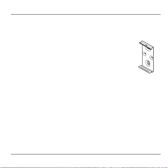
1 Helligkeitssensor-Modul HB 85
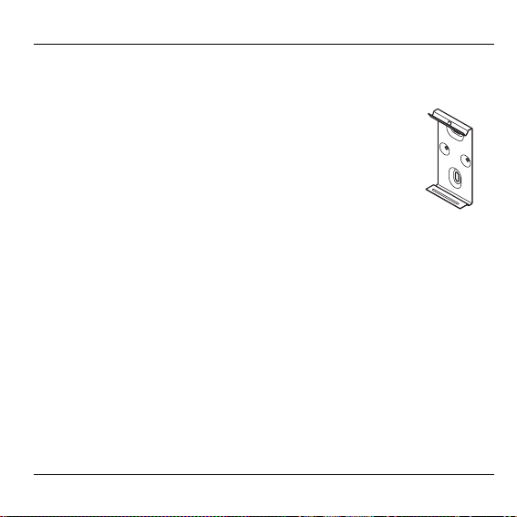
2 Befestigungsklammer
3 2 Batterien 1,5 V, Typ LR 06 (Mignon)
Zusätzlich im Lieferumfang HB 95
enthalten:
4 Verbindungskabel HCV 23
5 Flügelrad
5
Page 8

Montage
Montage
WARNUNG Unzureichende Datenübertragung!
Störung des Funksenders im Gerät durch metallische
Gegenstände und weitere Funkgeräte.
► Achten Sie bei der Wahl des Betriebsorts auf min-
destens 1 m Abstand zu Funkgeräten wie FunkKopfhörern, schnurlosen Telefonen nach DECTStandard etc.
► Achten Sie auf ausreichende Distanz zu metalli-
schen Gegenständen.
► Wählen Sie bei nicht zu behebender Funkstörung
einen anderen Montageort.
Die Helligkeits- und Temperatursensoren im Innern des Moduls sind auf die Beschaffenheit des Gehäuses abgestimmt.
► Gehäuse nicht mit Farbe überstreichen.
6
Page 9

Montage
Montage des Helligkeitssensor-Moduls
Die metallische Befestigungsklammer unterstützt die Funktion des
Funksenders.
► Geeigneten Montageort wählen.
► Sicherstellen, dass das waagerechte Schraubenloch
der Befestigungsklammer oben liegt.
► Befestigungsklammer mit Schrauben und Dübeln fest
auf dem Untergrund anbringen.
7
Page 10

Montage
Montage externer Sensoren
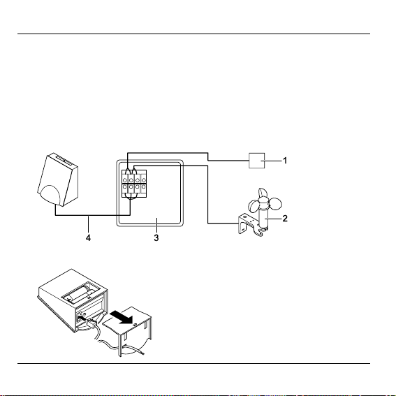
► Geeigneten Montageort wählen.
► Verteilerdose (Pos. 3) gemäß Montageanleitung des Herstellers in
der Nähe des Helligkeitssensor-Moduls montieren.
► Externe Sensoren (Pos. 1 und 2) an Klemmleiste in der Verteiler-
dose anschließen (siehe folgende Abbildung).
► Verbindungskabel HCV 23 an Helligkeitssensor-Modul anschlie-
ßen:
8
Page 11
Montage
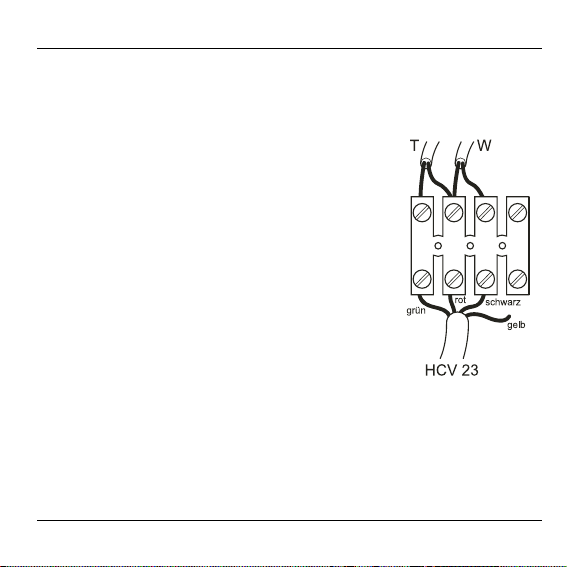
► Helligkeitssensor-Modul mit Verbindungskabel HCV 23 (siehe
Abbildung Seite 8, Pos. 4) an Klemmleiste in der Verteilerdose anschließen:
T Kabel zum externen Temperatur-
W Kabel zum Windsensor (Flügelrad)
HCV 23 Verbindungskabel zum Helligkeits-
Grün Externer Temperatursensor
Schwarz Windsensor
Rot Masse
Gelb Nicht belegt
sensor
sensor-Modul
9
Page 12

Inbetriebnahme
Inbetriebnahme
Teach-in durchführen
Externe Sensoren müssen vor dem Teach-in angeschlossen sein.
Der Teach-in bleibt am Hometronic Manager HCM 200D max.
4 min aktiv. Machen Sie sich zuvor mit den folgenden Schritten vertraut.
1. Teach-in am HCM 200D vorbereiten
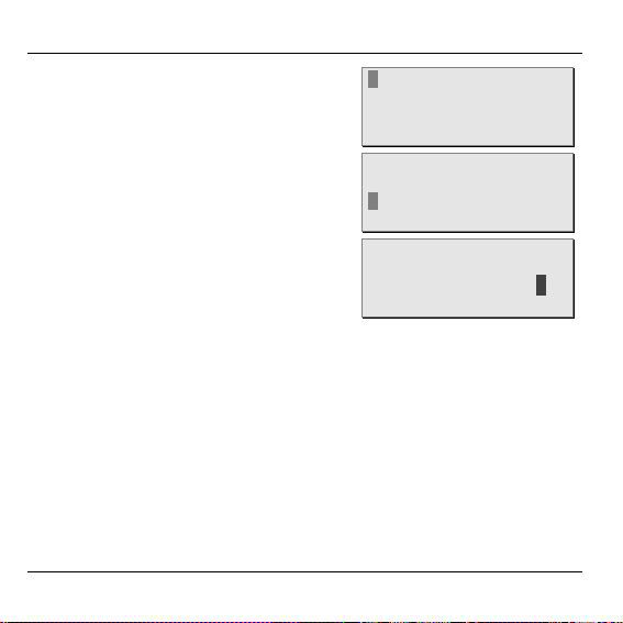
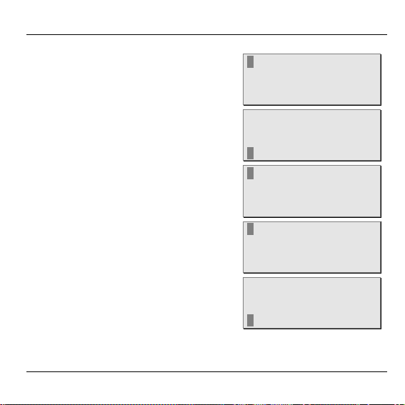
Der Hometronic Manager HCM 200D
zeigt die Standardanzeige, z. B.:
► Eingabeknopf drücken.
Der Cursor blinkt in der untersten
Zeile.
► Eingabeknopf nach rechts drehen,
bis „Menü“ markiert ist.
10
Hometronic
DO 01.03.2007 11:15
Kein Lifestyle aktiv
WOHNEN 20.0 C
Hometronic
DATUM/ZEIT STELLEN
LIFESTYLE AKTIVIEREN
WOHNEN 20.0 C
MENÜ
DATUM/ZEIT STELLEN
LIFESTYLE AKTIVIEREN
WOHNEN 20.0 C
Page 13

Inbetriebnahme
► Eingabeknopf drücken.
Im Display erscheint:
► Eingabeknopf nach links drehen, bis
„Einstellungen“ markiert ist.
LIFESTYLES
ZEITPROGRAMME
ANZEIGE
EINSTELLUNGEN
LIFESTYLES
ZEITPROGRAMME
ANZEIGE
► Eingabeknopf drücken.
Im Display erscheint:
► Eingabeknopf drücken.
Im Display erscheint:
► Eingabeknopf nach links drehen, bis
„Fühler“ markiert ist.
EINSTELLUNGEN
INSTALLATION
DE-INSTALLATION
FUNKTION ERWEITERUNG
FÜHLERFUNKTION
HEIZUNG
ROLLADEN
GERÄTE/LICHT
FÜHLER
HEIZUNG
ROLLADEN
GERÄTE/LICHT
FÜHLER
11
Page 14
Inbetriebnahme
► Eingabeknopf drücken.
► Im Display erscheint z. B.
(Beispiel: 2 Fühler bereits belegt)
► Eingabeknopf nach links drehen, bis
ein nicht belegter Fühler (z. B. „Fühler 3“) markiert ist.
► Eingabeknopf drücken.
Der Cursor erscheint auf der rechten
Seite.
Der Hometronic Manager HCM 200D ist für den Teach-in bereit.
FÜHLER-1 HELL
FÜHLER-2 TEMP
FÜHLER-3
FÜHLER-4
FÜHLER-1 HELL
FÜHLER-2 TEMP
FÜHLER-3
FÜHLER-4
FÜHLER-1 HELL
FÜHLER-2 TEMP
FÜHLER-3 .
FÜHLER-4
12
Page 15

Inbetriebnahme
2. Teach-in am Helligkeitssensor-Modul aktivieren
Um zu prüfen, ob die Funkverbindung für den späteren Betrieb gewährleistet ist, sollte das Helligkeitssensor-Modul
während des Teach-in möglichst nahe am Montageort bleiben.
► Helligkeitssensor-Modul aus Befesti-
gungsklammer nehmen.
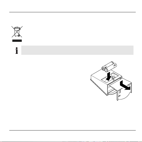
► Batteriefach öffnen.
► Teach-in-Taste kurz drücken
(siehe Abbildung Seite 16, Pos. 1).
► Batteriefach schließen und Helligkeits-
sensor-Modul in Befestigungsklammer
einsetzen.
Das Helligkeitssensor-Modul wird dem
Hometronic Manager HCM 200D
zugeordnet.
13
Page 16

Inbetriebnahme
3. Anzeige am HCM 200D bei erfolgreichem Teach-in
Im Display ist der Cursor durch einen
Stern ersetzt worden:
FÜHLER-1 HELL
FÜHLER-2 TEMP
FÜHLER-3 *
Nach kurzer Zeit wird der Stern durch
die Bezeichnung für die jeweilige
Sensorart ersetzt:
oder:
Beim HB 95 (mit Flügelrad) erscheint
im Display z. B.:
FÜHLER-4
FÜHLER-1 HELL
FÜHLER-2 TEMP
FÜHLER-3 HELL
FÜHLER-4 TEMP
FÜHLER-2 TEMP
FÜHLER-3 HELL
FÜHLER-4 TEMP
FÜHLER-5 WIND
Sollte der Fühlerwert nicht erscheinen, wiederholen Sie den
Teach-in.
14
Page 17

Inbetriebnahme
Erfolgreiches Teach-in
Nach erfolgreichem Teach-in sendet das Helligkeitssensor-Modul im
Abstand von ca. 10 min die Messdaten per Funk zum Hometronic
Manager HCM 200D. Deshalb reagieren die Rollläden verzögert auf
Änderungen der Sonneneinstrahlung und Windverhältnisse.
Wie Sie die Werte der Sensoren am Hometronic Manager
HCM 200D ablesen und die Funktionen anpassen, lesen Sie
in der Bedienungsanleitung des HCM 200D.
15
Page 18

Inbetriebnahme
Testsignale senden
Das Helligkeitssensor-Modul kann an den Hometronic Manager
HCM 200D ein Testsignal zur Überprüfung der Signalstärke senden.
► Im HCM 200D: „Menü/Einstellungen/Installation/Test MSG.
Empfangen“ wählen.
Im Display erscheinen folgende Angaben:
– Gerätenummer des Sensors
– Stärke des empfangenen Signals
(1 = ausreichend ... 5 = stark)
– Anzahl der empfangenen
Testnachrichten
► Teach-in-Taste am Helligkeitssensor-
Modul kurz drücken.
Das Helligkeitssensor-Modul sendet
alle 5 s eine Testnachricht an den
HCM 200D (ca. 10 min lang).
GERÄTE NR. 00-002628
FELDSTÄRKE 4
EMPFANGENE MSG. 212
16
Page 19
Batterien einlegen/wechseln
Batterien einlegen/wechseln
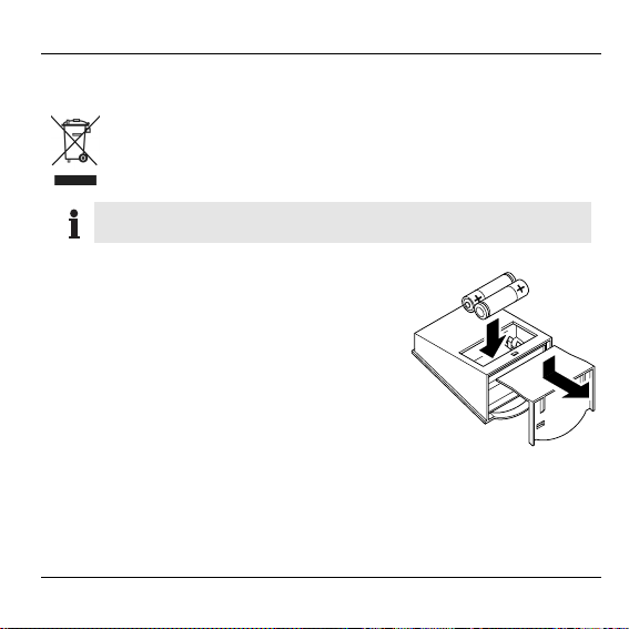
► Batteriefach öffnen.
► Ggf. alte Batterien entfernen.
► Neue Batterien mit der richtigen Polung
► Batteriefach schließen und Helligkeits-
Gebrauchte Batterien nicht mit dem Hausmüll, sondern entsprechend den gesetzlichen Bestimmungen entsorgen.
Immer beide Batterien wechseln.
Nur 1,5-V-Mignon-Batterien vom Typ LR06, AA verwenden.
einlegen.
sensor-Modul in Befestigungsklammer
einsetzen.
17
Page 20

Technische Daten
Technische Daten
Schutzklasse
IP 44 (HB 85)
IP 34 (HB 95)
Umgebungstemperatur –10 °C bis +50 °C
Lagertemperatur –20 °C bis +60 °C
Maximale Luftfeuchtigkeit
95 %
Max. Abmessungen (B x H x T) 72 x 76 x 50 mm
Energieversorgung
2 Batterien 1,5 V
Mignon Typ LR06
Messbereich Helligkeit 1 lx bis 100 000 lx
Messbereich Temperatur
–30 °C bis +70 °C
bei 0,1 °C Auflösung
Messbereich
11 km/h bis 144 km/h
Windgeschwindigkeit
Datenübertragungs-Intervall typisch: 2–6 min
18
Page 21
Hilfe im Problemfall
Hilfe im Problemfall
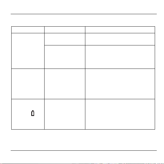
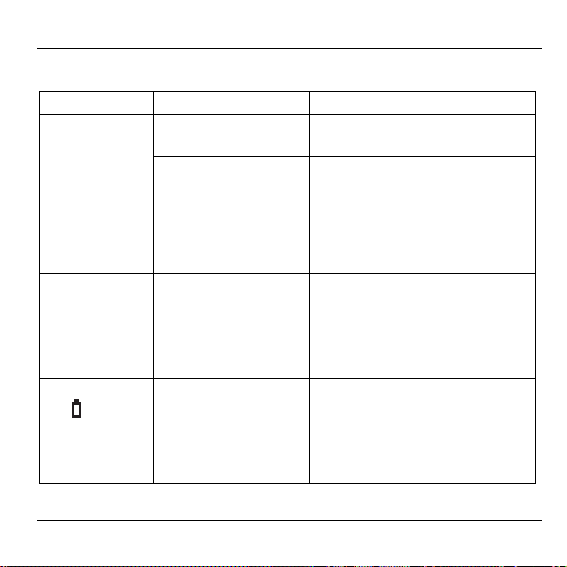
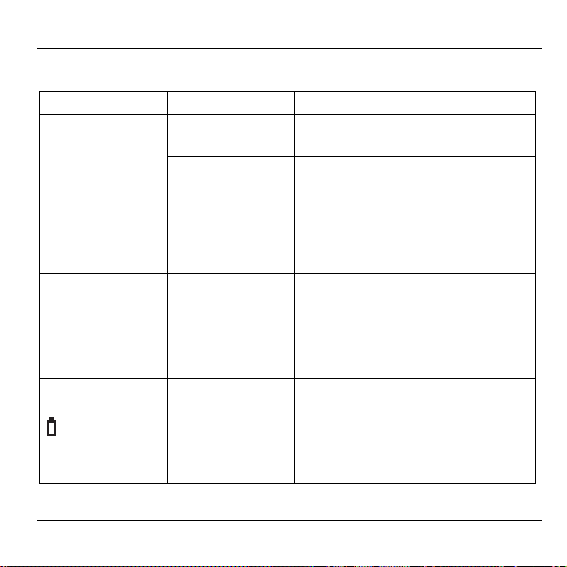
Problem Ursache Lösung
Teach-in fehlgeschlagen
Batterien falsch
eingelegt
Funkverbindung
gestört
► Batterien richtig einlegen.
► Störquellen (Metall, Funkge-
räte) beseitigen.
► Montageort des Helligkeits-
sensor-Moduls korrigieren.
Keine Steuerung durch
HCM 200D
HelligkeitssensorModul nicht oder
falsch zugeordnet
► Am HCM 200D „Fühler
einem Rollladen zuordnen“.
Anzeige des
Batterie-
symbols
Display des
HCM 200D
im
Batterie zu
schwach
► Ggf. Batterien wechseln.
19
Page 22

Hilfe im Problemfall
Problem Ursache Lösung
Anzeige eines
„!“ im Display
des HCM 200D
Fehler in der
Übertragung
oder Messfehler
im Helligkeitssensor-Modul
► Siehe auch Bedienungsan-
leitung des HCM 200D, Abschnitt „Hilfe im Problemfall“
► Batterien prüfen.
► Fühler und Fühlerzuordnung
prüfen.
► Kabel auf Beschädigungen
prüfen.
20
Page 23

Contents
Contents
Contents 21
Overview 22
Scope of delivery 23
Mounting 24
Mounting the brightness sensor module 25
Mounting external sensors 26
Commissioning 28
Performing binding 28
Successful binding 33
Transmitting test signals 34
Inserting/changing batteries 35
Technical data 36
Help with problems 37
21
Page 24

Overview
Overview
The Brightness Sensor Module HB 85 measures brightness and
external temperature, which are transferred to the operating device via
radio. This makes it possible, for example, to control shutters and
other devices based on brightness. Instead of a temperature sensor in
the housing, you could connect an additional external temperature
sensor.
The HB 85 can be connected to a vane anemometer for measurement
of wind speed. This set is sold as HB 95.
Use the Wind Sensor HWS 40 to control awnings.
22
Page 25

Scope of delivery
Scope of delivery
1 Brightness Sensor Module HB 85
2 Mounting bracket
3 Two 1.5 V batteries, type LR 06
(mignon)
The scope of delivery of HB 95 also includes:
4 Connection Cable HCV 23
5 Vane anemometer
23
Page 26

Mounting
Mounting
WARNING
Insufficient data transfer!
Interference of the radio transmitter in the device by
metallic objects and other radio devices.
► When selecting the operating site ensure that the
distance to radio devices such as radio headphones, cordless phones, etc. according to the
DECT standard is at least 1 m.
► Ensure that there is sufficient distance to metallic
objects.
► Select another mounting site if the radio interfer-
ence cannot be rectified.
The brightness and temperature sensors on the inside of the
module have been adapted to the conditions of the housing.
► Do not paint the housing.
24
Page 27
Mounting
Mounting the brightness sensor module
The metallic mounting bracket supports the function of the radio
transmitter.
► Select a suitable mounting site.
► Ensure that the horizontal screw hole of the mounting
bracket is positioned at the top.
► Use screws and dowels to fasten the mounting
bracket firmly to the subsurface.
25
Page 28

Mounting
Mounting external sensors
► Select a suitable mounting site.
► Mount the distribution box (Item 3) near the brightness sensor
module in accordance with the mounting instructions from the
manufacturer.
► Connect the external sensors (Items 1 and 2) to the terminal strip
in the distribution box (see following figure).
► Connect the Connection Cable HCV 23 to the brightness sensor
module:
26
Page 29

Mounting
► Connect the brightness sensor module to the terminal strip in the
distribution box with the Connection Cable HCV 23 (see figure on
Page 26, Item 4):
T Cable to the external temperature
W Cable to the wind sensor (vane
HCV 23 Connection cable to the brightness
Green External temperature sensor
Black Wind sensor
Red Earth
Yellow Not assigned
sensor
anemometer)
sensor module
27
Page 30

Commissioning
Commissioning
Performing binding
External sensors must be connected before binding.
Binding mode remains active for a max. of 4 min. at the
Hometronic Manager HCM 200D. Familiarize yourself with the
following steps beforehand.
1. Preparing for binding at the HCM 200D
The Hometronic Manager HCM 200D
shows the standard display, e.g.:
► Press the Input button.
The cursor flashes on the bottom
line.
► Turn the Input button to the right until
"Menu" is selected.
28
Hometronic
DO 01.03.2007 11:15
No lifestyle active
LIVING 20.0 C
Hometronic
SET DATE/TIME
ACTIVATE LIFESTYLE
LIVING 20.0 C
MENU
SET DATE/TIME
ACTIVATE LIFESTYLE
LIVING 20.0 C
Page 31
Commissioning
► Press the Input button.
The following is displayed:
► Turn the Input button to the left until
"Settings" is selected.
LIFESTYLES
TIME PROGRAMS
DISPLAY
SETTINGS
LIFESTYLES
TIME PROGRAMS
DISPLAY
► Press the Input button.
The following is displayed:
► Press the Input button.
The following is displayed:
► Turn the Input button to the left until
"Sensor" is selected.
SETTINGS
INSTALLATION
DE-INSTALLATION
SENSOR FUNCTION
DAYLIGHT SAVING TIME
HEATING/COOLING
SHUTTER
DEVICES/LIGHTS
SENSOR
HEATING/COOLING
SHUTTER
DEVICES/LIGHTS
SENSOR
29
Page 32

Commissioning
► Press the Input button.
The following, for example, is displayed (example: 2 sensors already
assigned)
► Turn the Input button to the left until a
free sensor (e.g. "Sensor 3") is selected.
► Press the Input button.
The cursor appears on the right-hand
side.
The Hometronic Manager HCM 200D is ready for binding.
SENSOR-1 BRIGHT
SENSOR-2 TEMP
SENSOR-3
SENSOR-4
SENSOR-1 BRIGHT
SENSOR-2 TEMP
SENSOR-3
SENSOR-4
SENSOR-1 BRIGHT
SENSOR-2 TEMP
SENSOR-3.
SENSOR-4
30
Page 33

Commissioning
2. Activating binding at the brightness sensor module
To check whether the radio connection is ready for later operation, the brightness sensor module should remain as near
as possible to the mounting site during binding.
► Remove the brightness sensor module
from the mounting bracket.
► Open the battery compartment.
► Press the Binding button briefly (see
figure on Page 34, Item 1).
► Close the battery compartment and
insert the brightness sensor module
into the mounting bracket.
The brightness sensor module is assigned to the Hometronic Manager
HCM 200D.
31
Page 34

Commissioning
3. Display at the HCM 200D if binding is successful
The cursor is replaced by an asterisk
in the display:
SENSOR-1 BRIGHT
SENSOR-2 TEMP
SENSOR-3 *
After a brief period the asterisk is replaced by the designation for the respective sensor type:
or:
In the case of the HB 95 (with vane
anemometer), the following is displayed, e.g.:
SENSOR-4
SENSOR-1 BRIGHT
SENSOR-2 TEMP
SENSOR-3 BRIGHT
SENSOR-4 TEMP
SENSOR-2 TEMP
SENSOR-3 BRIGHT
SENSOR-4 TEMP
SENSOR-5 WIND
If the sensor value does not appear, repeat binding.
32
Page 35

Commissioning
Successful binding
After successful binding, the brightness sensor module transmits the
measured data to the Hometronic Manager HCM 200D via radio at
intervals of approx. 10 minutes. This is why the shutters have a delayed reaction to changes in sunlight and wind.
For information on how to read values of the sensors at the
Hometronic Manager HCM 200D and adapt the functions,
please refer to the operating instructions of the HCM 200D.
33
Page 36

Commissioning
Transmitting test signals
The brightness sensor module can transmit a test signal to the Hometronic Manager HCM 200D to check the signal strength.
► In the HCM 200D, select "Menu/Settings/Installation/Receive
Test MSG.".
The following specifications appear in
the display:
– Device number of the sensor
– Strength of the received signal
(1 = sufficient, 5 = strong)
– Number of received test mes-
sages
► Press the Binding button on the bright-
ness sensor module briefly.
The brightness sensor module transmits a test message to the
HCM 200D every 5 seconds
(for approx. 10 minutes).
34
Source ID 00-002628
Field strength 4
Received Msg. 212
Page 37
Inserting/changing batteries
Inserting/changing batteries
► Open the battery compartment.
► Remove the old batteries if necessary.
► Insert new batteries, paying attention to
► Close the battery compartment and
Do not dispose of used batteries with household rubbish.
They must be returned in accordance with the local statutory
requirements.
Always replace both batteries.
Only use 1.5 V mignon batteries of type LR06, AA.
correct polarity.
insert the brightness sensor module
into the mounting bracket.
35
Page 38

Technical data
Technical data
Protection class
IP 44 (HB 85)
IP 34 (HB 95)
Ambient temperature –10 °C to +50 °C
Storage temperature –20 °C to +60 °C
Maximum humidity
95 %
Max. dimensions (W x H x D) 72 x 76 x 50 mm
Power supply
Two 1.5 V mignon
batteries of type LR06
Brightness measuring range 1 lx to 100.000 lx
Temperature measuring range
–30 °C to +70 °C
at 0.1 °C resolution
Wind speed measuring range 11 km/h to 144 km/h
Data transfer interval Typical: 2–6 min.
36
Page 39
Help with problems
Help with problems
Problem Cause Remedy
Binding failed
Batteries inserted
► Insert batteries correctly.
incorrectly
Radio connection
faulty
► Eliminate interference
sources (metal, radio devices).
► Correct mounting site of
the brightness sensor
module.
HCM 200D
not controlling
Brightness sensor
module not as-
► "Assign sensor to shut-
ters" at HCM 200D.
signed or assigned
incorrectly
Battery sym-
is dis-
bol
played in the
HCM 200D
Battery too weak
► Change the batteries, if
necessary.
37
Page 40

Help with problems
Problem Cause Remedy
"!" is displayed
by the HCM
200D
Error in the
transmission or
measuring error
in the brightness sensor
module
► Also refer to operating
instructions of HCM 200D,
"Help with problems"
► Check batteries.
► Check sensors and sensor
assignment.
► Check cabling for damage.
38
Page 41

Índice
Índice
Índice 39
Visión general 40
Volumen de suministro 41
Montaje 42
Montaje del módulo sensor de luminosidad 43
Montaje de sensores externos 44
Puesta en servicio 46
Ejecución de la sincronización 46
Sincronización eficaz 51
Transmisión de señales de prueba 52
Poner/Cambiar pilas 53
Características técnicas 54
Ayuda en caso de problemas 55
39
Page 42

Visión general
Visión general
El módulo sensor de claridad HB 85 mide la claridad y la temperatura
exterior, que se transmite por radio al aparato de mando. Con ello es
p.ej. posible controlar persianas u otros dispositivos en función de la
claridad ambiental. Como alternativa al sensor de temperatura
instalado en la caja puede usted conectar un sensor de temperatura
externo adicional.
El HB 85 se puede conectar a una rueda de paletas para medir la
fuerza del viento y está entonces disponible como conjunto HB 95.
Utilice para el mando de marquesinas el sensor de viento
HWS 40.
40
Page 43

Volumen de suministro
Volumen de suministro
1 Módulo sensor de claridad HB 85
2 Corchete de fijación
3 2 pilas 1,5 V, tipo LR 06 (Mignon)
El volumen de suministro HB 95
incluye además:
4 Cable de conexión HCV 23
5 Rueda de paletas
41
Page 44

Montaje
Montaje
ADVERTENCIA ¡Transmisión de datos deficiente!
Interrupción del radiotransmisor en el dispositivo
mediante objetos metálicos y otros aparatos de
radio.
► Preste atención al elegir el lugar de
instalación a una distancia mínima de 1 m a
aparatos inalámbricos, como auriculares o
teléfonos que cumplan la norma DECT, etc.
► Preste atención a que la distancia a los
objetos metálicos sea suficientemente
grande.
► En presencia de radiointerferencias
imposibles de eliminar, elija otro lugar de
montaje.
Los sensores de claridad y temperatura en el interior del
módulo están adaptados a la disposición de la caja.
► No aplicar pintura a la caja.
42
Page 45
Montaje
Montaje del módulo sensor de luminosidad
El corchete de fijación de metal soporta la función del radiotransmisor.
► Elegir un lugar de montaje adecuado.
► Asegurarse de que el agujero para tornillo horizontal
del corchete de fijación esté encima.
► Asegurar el corchete de fijación firmemente con
tornillos y tacos en el fondo.
43
Page 46
Montaje
Montaje de sensores externos
► Elegir un lugar de montaje adecuado.
► Montar la caja de distribución (Pos. 3) en la cercanía del módulo
sensor de claridad conforme a las instrucciones de montaje del
fabricante.
► Conectar los sensores externos (Pos. 1 y 2) a la regleta de bornes
de la caja de distribución (véase siguiente figura).
► Unir el cable de conexión HCV 23 al módulo sensor de claridad:
44
Page 47

Montaje
Conectar el módulo sensor de claridad con cable de conexión HCV 23
(véase figura en página 44, Pos. 4) a la regleta de bornes en la caja
de distribución:
T Cable para el sensor de
temperatura externo
W Cable para el sensor de viento
(rueda de paletas)
HCV 23 Cable de conexión para el módulo
sensor de claridad
Verde Sensor de temperatura externo
Negro Sensor de viento
Rojo Masa
Amarillo No asignado
45
Page 48

Puesta en servicio
Puesta en servicio
Ejecución de la sincronización
Los sensores externos deben conectarse antes de la sincronización.
La sincronización permanece máx. 4 min activa en el
Hometronic Manager HCM 200D. Familiarícese previamente
con los siguientes pasos.
1. Preparación de la sincronización en el HCM 200D
El Hometronic Manager HCM 200D
muestra la indicación estándar, p.ej.:
► Pulsar el botón de entrada de datos.
El cursor parpadea en la última línea
de abajo.
► Girar el botón de entrada de datos a
la derecha, hasta que esté marcado
"MENÚ".
46
Hometronic
MA 14.05.2007 10:00
Ningun lifestyle act
SALON 20.0 C
Hometronic
INTROD. FECHA/HORA
ACTIVAR LIFESTYLE
SALON 20.0 C
MENU
INTROD. FECHA/HORA
ACTIVAR LIFESTYLE
SALON 20.0 C
Page 49

Puesta en servicio
► Pulsar el botón de entrada de datos.
En la pantalla aparece:
► Girar el botón de entrada de datos a
la izquierda, hasta que esté marcado
"Ajustes".
► Pulsar el botón de entrada de datos.
En la pantalla aparece:
► Pulsar el botón de entrada de datos.
En la pantalla aparece:
► Girar el botón de entrada de datos a
la izquierda, hasta que esté marcado
"Sensor".
LIFESTYLES
PROGRAMAS HORARIOS
PANTALLA
AJUSTES
LIFESTYLES
PROGRAMAS HORARIOS
PANTALLA
AJUSTES
INSTALACION
DESINSTALACION
FUNCION SENSOR
HORA VERANO
CALEFAC./REFRIGERAC
PERSIANAS
APARATOS/LUCES
SENSOR
CALEFAC./REFRIGERAC
PERSIANAS
APARATOS/LUCES
SENSOR
47
Page 50

Puesta en servicio
► Pulsar el botón de entrada de datos.
En la pantalla aparece p.ej.
(Ejemplo: 2 sensores asignados)
► Girar el botón de entrada de datos a
la izquierda, hasta que esté marcado
un sensor no ocupado
(p.ej. el sensor "3").
► Pulsar el botón de entrada de datos.
El cursor aparece en el lado
izquierdo.
El Hometronic Manager HCM 200D está disponible para la
SENSOR-1 SOLEADO
SENSOR-2 TEMP
SENSOR-3
SENSOR-4
SENSOR-1 SOLEADO
SENSOR-2 TEMP
SENSOR-3
SENSOR-4
SENSOR-1 SOLEADO
SENSOR-2 TEMP
SENSOR-3 .
SENSOR-4
sincronización.
48
Page 51

Puesta en servicio
2. Activar la sincronización en el módulo sensor de claridad
Para comprobar si la conexión por radio está garantizada
para el servicio ulterior, el módulo sensor de claridad debe
permanecer en lo posible cerca del lugar de montaje durante
la sincronización.
► Sacar el módulo sensor de claridad del
corchete de fijación.
► Abrir el compartimento para pilas.
► Pulsar brevemente el botón de
sincronización
(véase figura en página 52, Pos. 1).
► Cerrar el compartimento para pilas y
colocar el módulo sensor de claridad
en el corchete de fijación.
El módulo sensor de claridad es
asignado al Hometronic Manager
HCM 200D.
49
Page 52

Puesta en servicio
3. Indicación en el HCM 200D para la sincronización eficaz
El cursor fue reemplazado por un
asterisco en la pantalla:
SENSOR-1 SOLEADO
SENSOR-2 TEMP
SENSOR-3 *
Después de corto tiempo el asterisco
es reemplazado por la clase de
sensor correspondiente:
o:
En el HB 95 (con rueda de paletas)
aparece en la pantalla p.ej.:
SENSOR-4
SENSOR-1 SOLEADO
SENSOR-2 TEMP
SENSOR-3 SOLEADO
SENSOR-4 TEMP
SENSOR-2 TEMP
SENSOR-3 SOLEADO
SENSOR-4 TEMP
SENSOR-5 VIENTO
Si el parámetro del sensor no aparece, repita la
sincronización.
50
Page 53

Puesta en servicio
Sincronización eficaz
Después de la sincronización eficaz, el módulo sensor de claridad
transmite a intervalos de aprox. 10 min los datos de medición por
radio al Hometronic Manager HCM 200D. Por ese motivo, las
persianas reaccionan retrasadas a los cambios de los rayos del sol y
el viento.
La descripción de la forma cómo usted puede leer los
parámetros de los sensores en el Hometronic Manager
HCM 200D y adaptar las funciones, puede verla en el manual
de instrucciones del HCM 200D.
51
Page 54

Puesta en servicio
Transmisión de señales de prueba
El módulo sensor de claridad puede transmitir al Hometronic Manager
HCM 200D una señal de prueba para comprobar la intensidad de
señal.
► En el HCM 200D: Elegir "Menú/Ajustes/Instalación/Test MSG.
Recepción".
En la pantalla aparecen los
siguientes datos:
– Número de aparato del sensor
– Intensidad de campo (1 =
suficiente ... 5 = fuerte)
– Número de los mensajes de test
recibidos
► Pulsar el botón de sincronización
brevemente en el módulo sensor de
claridad.
El módulo sensor de claridad transmite
cada 5 s un mensaje de test al
HCM 200D (de unos 10 min).
52
Aparato número 002628
Intensidad de campo 4
Mensajes recibidos 212
Page 55

Poner/cambiar pilas
Poner/cambiar pilas
► Abrir el compartimento para pilas.
► Dado el caso, quitar las pilas gastadas.
► Poner pilas nuevas con la polaridad
► Cerrar el compartimento para pilas y
No tire las pilas usadas a la basura, deposítelas en los
lugares adecuados de acuerdo con las normativas legales
al respecto.
Cambie siempre las dos pilas.
Utilice únicamente pilas Mignon de 1,5 V del tipo LR06, AA.
correcta.
colocar el módulo sensor de claridad
en el corchete de fijación.
53
Page 56

Características técnicas
Características técnicas
Clase de protección
IP 44 (HB 85)
IP 34 (HB 95)
Temperatura ambiente –10 °C hasta 50 °C
Temperatura de almacenaje –20 °C hasta 60 °C
Humedad máxima del aire
95 %
Medidas máx. (B x H x L) 72 x 76 x 50 mm
Alimentación energética
2 pilas 1,5 V
Mignon tipo LR06
Rango de medida de claridad 1 lx hasta 100 000 lx
Rango de medida de
temperatura
Rango de medida
–30 °C hasta +70 °C
con resolución de 0,1 °C
11 km/h hasta 144 km/h
velocidad del viento
Intervalo de transmisión de
datos
Típico: 2–6 min
54
Page 57
Ayuda en caso de problemas
Ayuda en caso de problemas
Problema Causa Solución
Sincronización
fallida
Pilas mal
puestas
Conexión por
radio
perturbada
► Poner las pilas
correctamente.
► Eliminar las fuentes
perturbadoras (metal,
aparatos de radio).
► Corregir el lugar de montaje
del módulo sensor de
claridad.
Ningún mando
a través del
HCM 200D
Módulo no
asignado o
asignación
► En el HCM 200D "asignar el
sensor a una persiana".
errónea
Indicación del
símbolo de pila
en la pantalla
del HCM 200D
Pilas
demasiado
débil
► Dado el caso, cambiar las
pilas.
55
Page 58

Ayuda en caso de problemas
Problema Causa Solución
Indicación de
un "!" en la
pantalla del
HCM 200D
Fallo en la
transmisión o
error de medida
en el módulo
sensor de
claridad
► Véase también la
instrucciones de manejo del
HCM 200D, sección "Ayuda
en caso de problemas"
► Comprobar las pilas.
► Comprobar el sensor y la
asignación de sensores.
► Comprobar la presencia de
daños en los cables.
56
Page 59

Page 60

Manufactured for and on behalf of the Environmental and Combustion Controls
Division of Honeywell Technologies Sàrl, Ecublens, Route du Bois 37, Switzerland
by its Authorized Representative:
Honeywell GmbH
Böblinger Straße 17
71101 Schönaich, Germany
Tel.: (++49) (0) 7031 637 01
Fax: (++49) (0) 7031 637 493
http://europe.hbc.honeywell.com
This document is definitive for the enclosed product and replaces all previous
publications.
Honeywell Inc. hereby declares that this device complies with the basic
requirements and other relevant regulations of guideline 1999/5/EC. The declaration
of conformity of the product can be requested from the manufacturer.
Note to non-EU countries: This product may only be used if operation in the
868 MHz frequency band is permissible.
MU2H-0333GE51 R0607A
 Loading...