

Page 1
Sun Module
HB 05 / HB 15
Mounting and Operation
Page 2

Page 3

Contents
Contents
Contents 1
Overview 2
For your information 2
Application 2
Scope of supply 4
Mounting 5
Safety instructions 5
Information on mounting the sun module 5
Information on mounting external sensors 6
Mounting the sun module 7
Inserting batteries 8
Mounting external sensors 9
Teach-in 12
Operation 16
Information for the fitter 16
Glossary 17
Technical data 18
Help for problems 19
Notes 21
1
Page 4

Overview
Overview
For your information
Technical terms are identified by an * and are explained in the
glossary.
Application
The Sun module HB 05/HB 15 is part of the Hometronic System*. It
measures the brightness and temperature outside a building. The
housing of the sun module contains:
• 1 sensor for measuring the brightness
• 1 sensor for measuring the temperature
The measuring data* are transferred by radio to the Hometronic
Manager*. These data are used by the Hometronic Manager to control
the shutters which are assigned to the sun module via the following
functions:
• Opening the shutters at sunrise (SR)
• Sun protection (SP) in case of intensive sunshine and depending on
the outside temperature
• Closing the shutters at sunset (SS)
• Automatic brightness control (HA) for controlling the lamp
brightness via brightness values of the HB 05/HB 15 or controlling a
device with the device switch HS 20 or HS 30.
2
Page 5
Overview
• In the case of Version HB 15 with a connected vane anemometer*:
Opening or closing the shutters depending on the wind forces (wind
protection*)
Use the wind sensor HWS 40 to control the awnings.
You can connect further external sensors to the sun module:
• A temperature sensor to the HB 05 (alternatively to the temperature
sensor in the housing)
• A temperature sensor and a vane anemometer to the HB 15
3
Page 6
Overview
y
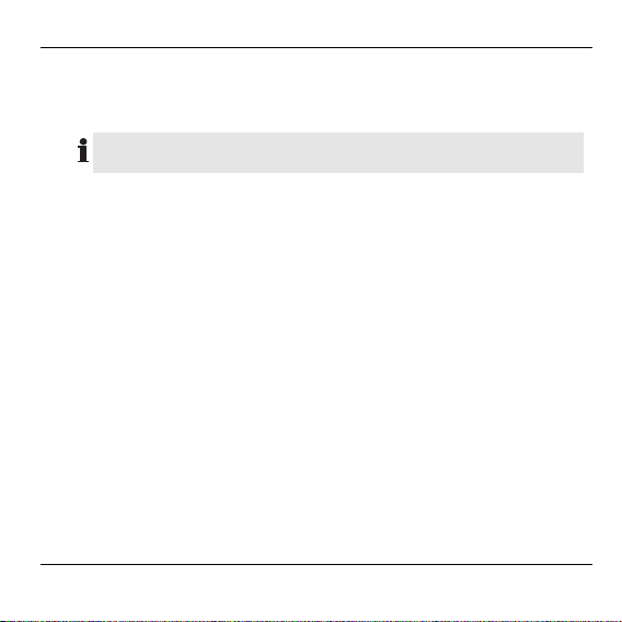
Scope of supply
(1) Sun module
(2) Mounting bracket
(3) 2 batteries 1.5 V, type LR 06
(mignon)
Additionally in the Sun
module HB 15 scope of suppl
(4) Connection cable (HCV 23)
(5) Vane anemometer
4
Page 7

Mounting
Mounting
Safety instructions
The sun module has a radio transmitter whose function
can be impaired by metallic objects or radio devices.
Caution!
► When selecting the mounting site, ensure that there is
sufficient distance to metallic objects and radio
devices.
► Select a different mounting site if radio interference
occurs.
The brightness and temperature sensors in the inside of
the module have been adapted to the housing state.
Caution!
Information on mounting the sun module
When selecting the mounting site, ensure that ...
• the sun module is easily accessible for the teach in* and the battery
change
• the brightness situation at the building is determined unimpaired as
far as possible
► Do not coat the housing.
► Avoid rough damage to the housing.
5
Page 8
Mounting
If you only install one sun module, select the mounting site in
accordance with its main application: Your Hometronic Manager uses
the measured data to control e.g. the position of the shutters at
sunrise or sunset. For measured data ...
• at sunrise: Align the sun module to face East
• at sunset: Align the sun module to face West
• for the whole day: Align the sun module to face South
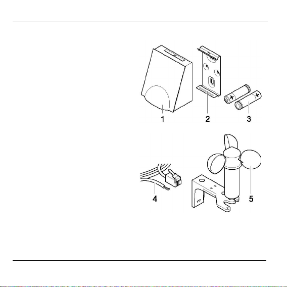
Information on mounting external sensors
In order to connect external sensors you require:
(1), (2) Cable from the distribution box to the external sensors
(3) Damp-proof distribution box
(4) Connection cable (HCV 23) to the sun module
6
Page 9

Mounting
When selecting the mounting site, ensure that ...
• the function of the external sensors is not impaired by an unsuitable
mounting site
• the external temperature sensor is not subject to direct sun
irradiation
• the wind conditions at the vane anemometer correspond to those at
the assigned shutters
• the vane anemometer is not positioned sheltered from the wind
Mounting the sun module
1. Mounting the mounting bracket
The metallic mounting bracket supports the function of the radio
transmitter.
When mounting the unit, ensure that the horizontal screw
hole of the mounting bracket is positioned at the top.
► Select a suitable mounting site.
► Use suitable screws and dowels to fasten the
mounting bracket firmly to the underground.
7
Page 10

Mounting
Inserting batteries
► If necessary, take the sun module out
of the mounting bracket.
► Open the battery compartment:
– Press in the battery lid.
– Pull up the housing frame.
– Remove the battery lid.
► Remove the old batteries, if necessa-
ry.
Batteries should not be disposed of in the household garbage.
You may be required by local law to dispose of used batteries
in a certain manner.
► Dispose of used batteries in conformance with the local statutory
requirements.
Always replace both batteries.
Only use 1.5 V mignon batteries of the type LR06.
► Insert the batteries into the battery compartment. Ensure that the
polarity is correct!
► Close the battery compartment and insert the sun module into the
mounting bracket.
Mounting of the sun module is now complete.
8
Page 11
Mounting
Mounting external sensors
1. Mounting a damp-proof distribution box
► Mount the damp-proof distribution box at a suitable location near the
sun module before connecting the external sensors. Observe the
corresponding mounting instructions of the manufacturer!
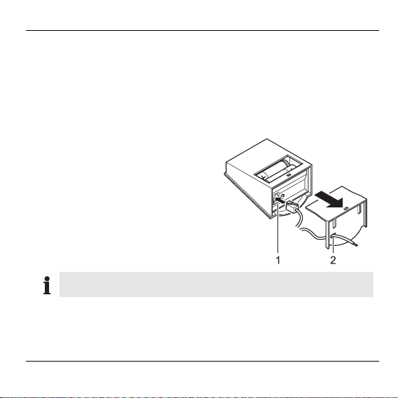
2. Connecting the sun module to the distribution box
► Remove the sun module from the
mounting bracket and open the
battery compartment.
► Insert the plug of the connecting
cable into the connecting socket of
the sun module (1).
► Open the cable opening (2).
► Insert the connecting cable.
The yellow conductor at the open end of the connecting cable
is not required to connect external sensors.
9
Page 12

Mounting
► If necessary, shorten the yellow conductor at the open cable end.
► Connect the connecting cable (HCV 23) to the terminal strip in the
distribution box as shown in the diagram below.
T Cable to the external temperature
sensor
W Cable to the vane anemometer
HCV 23 Connection cable to the sun module
Green External temperature sensor
Black Vane anemometer
Red Ground
Yellow unengaged
► Close the battery compartment.
► Insert the sun module back into the mounting bracket.
10
Page 13

Mounting
3. Mounting external sensor(s)
The maximum cable length between the sun module and the
temperature sensor amounts to 3 m, between the sun module
and the vane anemometer 8 m.
► Select a suitable mounting site.
► Mount external sensor(s) in accordance with the mounting instruct-
ions of the manufacturer.
► Prepare the cables to the required length.
► Lay the cables from the external sensor(s) to the distribution box.
4. Connecting external sensor(s) to the distribution box
► Wire the cable to the vane anemometer in accordance with the
diagram on Page 9.
► Wire the cable to the vane anemometer in accordance with the
diagram on Page 9.
Mounting of the external sensor(s) has been completed.
11
Page 14

Mounting
Teach-in
If you use external sensors, these have to be mounted before you
carry out the teach-in.
The teach-in mode remains active for a max. of 4 min. at the
Hometronic Manager. Familiarize yourself with the following
steps beforehand.
1. Activating the teach-in mode at the Hometronic Manager
The Hometronic Manager shows the
standard display, e.g.:
► Press the Dial button.
The cursor flashes in the bottom line.
► Turn the Dial button to the right until
"Menu" is selected.
► Press the Dial button.
The following text is displayed:
12
Hometronic
WE 03.07.2002 11:15
no lifestyle active
LIVING 20.0 C
Hometronic
SET DATE/TIME
ACTIVATE LIFESTYLE
LIVING 20.0 C
MENU
SET DATE/TIME
ACTIVATE LIFESTYLE
LIVING 20.0 C
LIFESTYLES
TIME PROGRAMS
DISPLAY
SETTINGS
Page 15
► Turn the Dial button to the left until
"Settings" is selected.
► Press the Dial button.
The following text is displayed:
► Press the Dial button.
The following text is displayed:
► Turn the Dial button to the left until
"Sensor" is selected.
► Press the Dial button.
In this example, 2 sensors are already assigned:
► Turn the Dial button to the left until a
free sensor (e.g. "Sensor 3") is
selected.
Mounting
LIFESTYLES
TIME PROGRAMS
DISPLAY
SETTINGS
INSTALLATION
DE-INSTALLATION
FUNCTION EXPANSION
SENSOR FUNCTION
HEATING/COOLING
SHUTTERS
DEVICES/LIGHTS
SENSOR
HEATING/COOLING
SHUTTERS
DEVICES/LIGHTS
SENSOR
SENSOR-1 BRIGHT
SENSOR-2 TEMP
SENSOR-3
SENSOR-4
SENSOR-1 BRIGHT
SENSOR-2 TEMP
SENSOR-3
SENSOR-4
13
Page 16
Mounting
► Press the Dial button.
A rectangle is displayed at the
selected sensor.
SENSOR-1 BRIGHT
SENSOR-2 TEMP
SENSOR-3 .
SENSOR-4
The Hometronic Manager is ready for the teach-in mode.
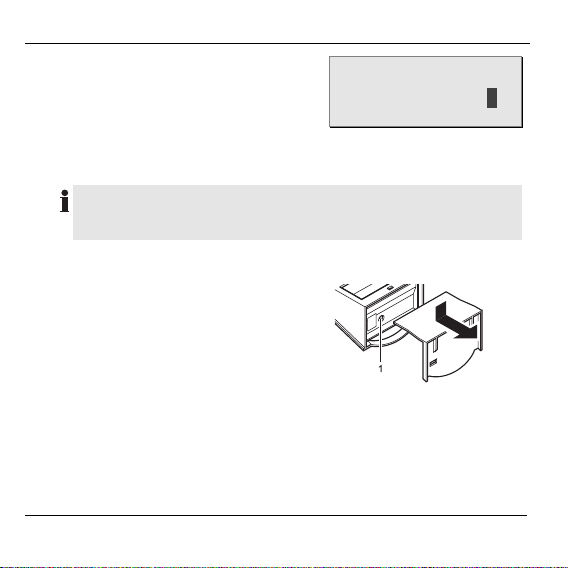
2. Activating the teach-in mode at the sun module
In order to check whether the radio connection is ensured for
later operation, the sun module should remain as near as
possible to the mounting site during the teach-in mode.
► Remove the sun module from the
mounting bracket.
► Open the battery compartment.
► Press the teach-in button (1)
briefly.
The teach-in mode at the sun
module is activated.
► Close the battery compartment and insert the sun module back into
the mounting bracket.
The sun module is assigned to the Hometronic Manager.
14
Page 17
Mounting
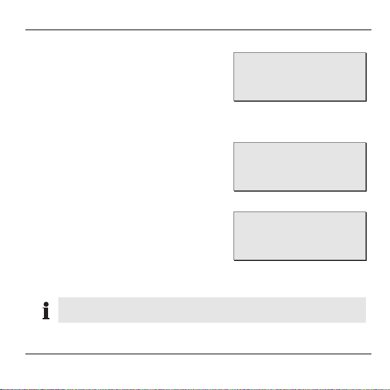
3. Display at the Hometronic Manager if the teach-in is successful
The rectangle is replaced by an
asterisk in the display:
The Hometronic Manager recognizes that the Sun module HB 05 has
two different sensors (brightness and temperature) and therefore
reserves the next sensor correspondingly.
After a brief period, the asterisk is
replaced by the designation for the
respective sensor type.
or:
If you have connected a vane anemometer to the HB 15, e.g. the
following text is displayed:
The teach-in was successful. The sun module and, if appropriate,
the external sensors are assigned to the Hometronic Manager.
SENSOR-1 BRIGHT
SENSOR-2 TEMP
SENSOR-3 *
SENSOR-4
SENSOR-1 BRIGHT
SENSOR-2 TEMP
SENSOR-3 BRIGHT
SENSOR-4 TEMP
SENSOR-2 TEMP
SENSOR-3 BRIGHT
SENSOR-4 TEMP
SENSOR-5 WIND
If the teach-in is has failed, it has to be repeated. To this
purpose, read the section "Help for problems" on Page 19.
15
Page 18
Operation
Operation
After a successful teach-in, the sun module (with the external sensors)
sends the measured data by radio to the Hometronic Manager in
intervals of approx. 10 minutes. The shutters and lights therefore react
with a corresponding delay to changes in the intensity of the sunlight.
For information on how to read values of the sensors at the
Hometronic Manager and adapt the functions, please refer to
the operating instructions of the Hometronic Manager.
Information for the fitter
After the sun module has been mounted, you should inform your
customer about the Hometronic System.
► Familiarize your customer with the operation of the Hometronic.
► Explain the manual operation of the components.
► Point out particular features and extension possibilities of the
respective customer installation.
16
Page 19

Glossary
External sensor
Additional sensor for the sun
module with which e.g. further
sensors are controlled.
Sensor
Device for measuring wind,
brightness, temperature, etc., for
example a temperature sensor or
a vane anemometer.
Hometronic Manager
Central operating device of
Hometronic.
Hometronic System
Modular home automation system of Honeywell.
Measuring data
Values which are transmitted by
the external sensors to the
Hometronic Manager.
Glossary
Teach-in
Assignment of the sun module to
the Hometronic Manager.
Temperature sensor
Sensor for measuring the outside
temperature.
Vane anemometer
Hometronic component which
measures wind speeds at the outer wall of the building. Depending on the measured data provided by the vane anemometer the
Hometronic Manager activates
the automatic wind protection for
shutters.
Wind protection
Protection of shutters against
damage through storms. The
shutters cannot be operated as
long as the wind protection is
active.
17
Page 20
Technical data
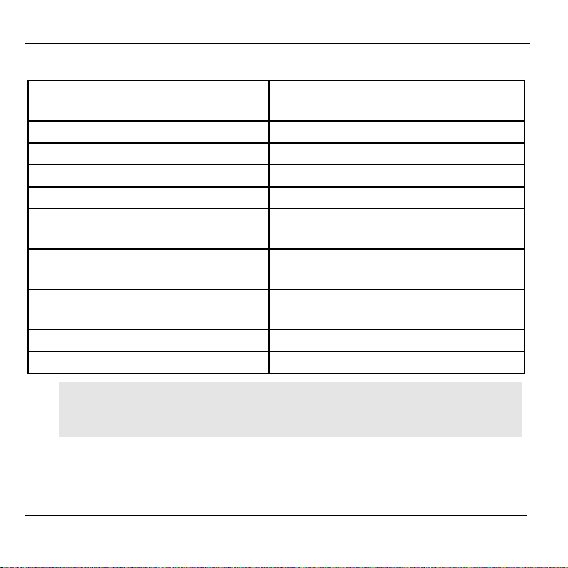
Technical data
Degree of protection IP 44 (HB 05)
IP 34 (HB 15)
Operating temperature range –10 °C to +50 °C *
Storage temperature range –20 °C to +60 °C
Max. relative humidity 95% (non-condensing)
Max. dimensions (W x H x D) 72 x 76 x 50 mm
Power supply 2 batteries 1.5 V
Mignon type LR6
Luminosity (brightness) measu-
ring range
Temperature measuring range
1 lx to 100 000 lx
–30 °C to +70 °C
at 0.1 °C resolution (HB 05)
Wind speed measuring range 11 km/h to 144 km/h (HB 15)
Data transfer interval Typical: 2–6 min
Batteries of the type Energizer HI Energy Lithium extend the
*
permitted operating temperature range of the sun module to
–20 °C to +60 °C.
18
Page 21

Help for problems
Problem Cause Remedy
Teach-in
failed
No control
by Hometronic Manager
Batteries inserted
incorrectly
Radio connection
faulty
Batteries inserted
incorrectly
Radio connection
faulty
Sun module not
assigned or
assigned
incorrectly
► Insert the batteries correctly.
► Eliminate interference sources
(metal, radio devices).
► Correct the mounting site of the
sun module.
► Insert the batteries correctly.
► Eliminate interference sources
(metal, radio devices).
► Change the batteries at the
Hometronic Manager.
► Repeat the teach-in.
► "Save the settings" at the
Hometronic Manager.
► "Assign a sensor to a shutter"
at the Hometronic Manager.
Help for problems
19
Page 22

Help for problems
Problem Cause Remedy
Battery
symbol
displayed in
the Hometronic
Manager
is
Battery too
weak
► Check at which Hometronic
module the batteries are weak.
► Change the batteries, if
necessary.
► Also refer to the operating in-
structions of the Hometronic
Manager.
"!“ is
displayed in
the Hometronic Manager
Error in the
transmission
or measuring
error in the
sun module
► Also refer to the operating
instructions of the Hometronic
Manager, "Help for problems"
► Check where the signal comes
from.
► Check the batteries.
► Check the sensors and sensor
assignment.
► Check the cables for damage.
20
Page 23

Notes
Notes
21
Page 24
Honeywell AG
Böblinger Straße 17
D – 71101 Schönaich
Telephone (+49) 7031 637-300
This company is certificated to
Ra di o f re que nc y r egi st rat io n: A, B, CH, D, DK, E, F, FIN, IT, LUX, N, NL, UK:
The right is reserved to make modifications. This document is definitive for the
enclosed product and replaces all previous publications.
No. 7157498 EN1H-0156 GE51R0802
 Loading...