

Page 1
Hometronic
ball valve
HAV 20, 25, 32
Mounting and operation
Page 2

Application
Application
The motor-driven Hometronic ball valve HAV opens or closes drinking
water conduits by means of a ball valve. It is controlled by the Hometronic Manager and allows e.g. watering during the owner's absence
while at the same time protecting from damage caused by water.
The ball valve is available in the nominal diameters DN 20, DN 25 and
DN 32. It is available ready to be mounted with drive and connecting
cable.
The ball valve has a very low noise level. It can be operated without a
tool in case of a power failure. The valve state (open/closed) is indicated
mechanically.
Page 3
Mounting
Mounting
Danger to life through electric shock!
Danger!
Live contacts are exposed while the module is being
connected electrically. Touching a live contact can cause
critical injuries.
► All work may only be carried out by authorized
specialized personnel.
► De-energize the corresponding fuse during all work on
the module.
It is advisable to install a cleaning filter in order to prolong the
service life of the valve and to protect the seals against
mechanical damage. Observe the relevant regulations, e.g. DIN
1988.
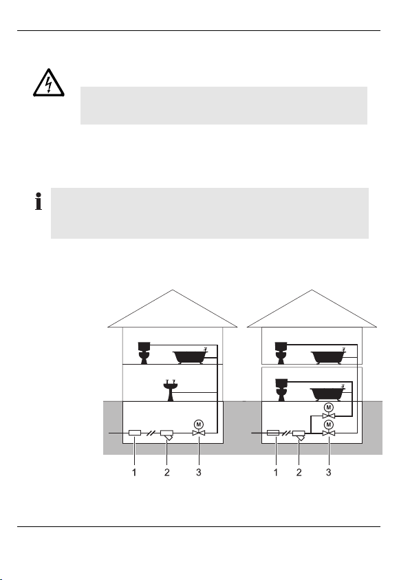
Selecting the mounting site
Depending on the mounting site selected, the ball valve can be used to
control the water supply of an entire house or of an individual apartment.
1. Existing
plumbing on
site (e.g. shutoff valve)
2. Cleaning filter
(may already
exist)
3. Ball valve
Page 4

Mounting
The ball valve can impair the function of sprinkler systems
Caution!
► Loosen the 2 screws M 6x15 (3)
on the bottom of the drive (1).
► Lift the drive off the valve (2).
► Install the ball valve at the
corresponding plumbing by
using a suitable tool (openended spanner).
► Mount the device switch HS 30
as described in the mounting
and operating instructions of the
device switch. Ensure that the
cable has the right length!
Electrical connection
► Install an all-pole switch
with 3 mm opening on
site in the incoming
line.
► W ire the device switch
and ball valve in
accordance with the
adjacent diagram and
connect them to the
power supply.
or similar water-based extinguishing systems.
Before mounting the module check whether an extinguishing
system is installed or is to be installed.
► If appropriate, select a different mounting site.
Page 5

Mounting
Assembling the ball valve
When selecting the mounting site
ensure that:
• The ball valve is accessible and
operable when power fails.
• The drive is mounted parallel to
the plumbing.
Right
Mounting of the drive upside down
or transverse to the plumbing is
not allowed.
Wrong
► Place the drive on the valve. Observe the plumbing direction!
► Screw the drive to the valve by using the 2 screws M 6x15.
► Assign the device switch HS 30 to the Hometronic Manager as
described in the operating instructions of the device switch.
Mounting has been completed.
Page 6

Operation
Operation
Manual operation
The ball valve can be operated
manually if the power fails:
► Press the drive to the valve (1).
► Turn the drive by 90°(2).
The valve is closed.
Indication of the valve state (open/closed)
When the drive has been removed
Position of the valve axis:
(1) Closed
(2) Open
When the drive is mounted
Colored triangle in the indicator window
(1):
Red: Open
No Color: Closed
Page 7

Technical data
Technical data
Type designation
Weight
Nominal width
Power supply
Limit switch
Power (operation consumption)
Power (standby consumption)
Protection standard
Protection class
Dimensions
Rotation time
Max. operating pressure
Max. initial torque
Connecting cable
Dimensions
HAV 20 HAV 25 HAV 32
0.88 kg 1.10 kg 1.42 kg
DN 20 DN 25 DN 32
230 V AC +6 ...–15% 50...60 Hz
5 (1) A, 230 V, 50 Hz
7.5 VA
3 VA
IP 44 conforming to IEC 529
2 conforming to EN 60335-1
Refer to "Dimensions"
30 sec for 90°
PN 16
8 Nm
4 x 0.5 mm, 2 m
Des. G KVS PN A B C D E H
HAV 20 ¾ " 4116 144 124.5 19.5 90.5 77.5 84
HAV 25 1 "68 16 153 129.5 23.5 104 90 93
HAV 32 1 ¼ " 123 16 163 134.5 28.5 119.5 105.5 103
All dimensions in mm, KVS in m3/h
Page 8

Honeywell AG
Böblinger Straße 17
D – 71101 Schönaich
Telephone ++49 (0) 7031 637-300
The right is reserved to make
modifications
This document is definitive for the enclosed product and replaces all previous
publications.
7157663 EN1H-0165GE51 R0403
This company is certified to
 Loading...