

Page 1
H46D Humidity Controller
INSTALLATION INSTRUCTIONS
APPLICATION
The H46D Humidity Controller is used with portable and
central unit humidifiers. The H46 has an spst, snap-acting
switch designed for line or low voltage circuits and two
leadwires for switch box mounting.
INSTALLATION
When Installing this Product…
1. Read these instructions carefully. Failure to follow
them could damage the product or cause a hazardous condition.
2. Check the ratings given in the instructions and on
the product to make sure the product is suitable for
your application.
3. Installer must be a trained, experienced service
technician.
4. After installation is complete, check out product
operation as provided in these instructions.
CAUTION
Disconnect power supply before connecting wiring
to avoid electrical shock or equipment damage.
Location
Select a location about 5 ft (1.5m) above the floor in an
area with good circulation at average temperature and
humidity for the area to be controlled. Avoid locations near
hot or cold air ducts and discharge air from the controlled
equipment.
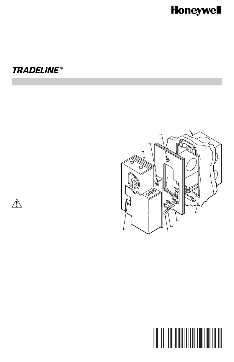
Mounting
쐃 Remove the setting knob.
쐇 Pull the cover forward from the device to remove.
쐋 Install a 2 x 3 in. (51 mm x 76 mm) vertical switch
box at the selected location.
쐏 Using the two screws provided, fasten the adapter
plate to the switch box as shown. See Fig. 1.
쐄 Pull the wires from the switch box through the
opening in the adapter plate and connect to the H46
leadwires with the solderless connectors provided.
See Fig. 2 through 4 for typical hookup.
쐂 Push the wires back into the switch box.
쐆 Place the H46 against the adapter plate, making
certain the tab at the bottom of the plate fits into the
notch on the H46.
쐊 Fasten the H46 to the adapter plate by tightening
the captive screw.
쐎 Replace the cover and the setting knob.
2 X 3 IN.
ADAPTER PLATE
SCREWS (2)
H46 CAPTIVE
MOUNTING SCREW
H46
(COVER OFF)
NYLON
ELEMENT
Fig. 1. Mounting H46D on vertical switch box.
SWITCH BOX
ADAPTER PLATE
PLATE TAB
H46 LEADWIRES (2)
WALL SURFACE
M7907
Wiring
Disconnect power supply before connecting wiring to avoid
electrical shock or equipment damage. All wiring must
comply with local codes and ordinances. Do not exceed
contact and coil ratings when wiring into the system.
See Fig. 2.
®U.S. Registered Trademark
Copyright © 1996 Honeywell Inc. • All Rights Reserved
X-XX UL
69-1001B
Page 2
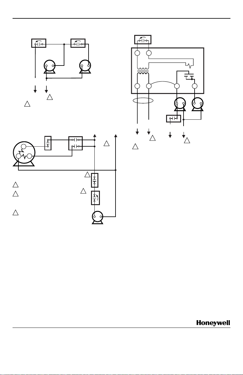
H46D HUMIDITY CONTROLLER
FAN
CONTROLLER
TEMPERATURE
RISE
FAN MOTOR
L1
(HOT)
L2
POWER
1
SUPPLY
PROVIDE DISCONNECT MEANS AND OVERLOAD
1
PROTECTION AS REQUIRED.
Fig. 2. Typical wiring diagram for H46D single-speed
FAN CONTROL
FAN MOTOR
LO
C
PROVIDE DISCONNECT MEANS AND
1
OVERLOAD PROTECTION AS REQUIRED.
2
TO ENSURE HUMIDIFIER OPERATION
IN WINTER WHEN THERMOSTAT
SUBBASE FAN SWITCH IS AT ON OR
AUTO, ADD SAIL SWITCH TO SYSTEM
AS SHOWN.
TO PREVENT HUMIDIFIER OPERATION
3
IN SUMMER, TURN H46D KNOB
TO OFF POSITION.
L4068
HI
H46D
CONTROLLER
fan motor.
COOLING
RELAY R8230
HUMIDITY
FALL
SAIL
SWITCH
S688A
H46D
HUMIDITY
CONTROL
HUMIDIFIER
MOTOR
HUMIDIFIER
M7910
2
3
L1 (HOT)
POWER
SUPPLY
1
HUMIDITY
FALL
M7911
H46D
HUMIDITY
FALL
RA89A RELAY
TT
TRANSFORMER
JUMPER
REMOVED
21 3
FAN
MOTOR
FAN
CONTROL
L1
(HOT)
L2
L2
POWER
SUPPLY
PROVIDE DISCONNECT MEANS AND OVERLOAD
1
PROTECTION AS REQUIRED.
Fig. 4. Typical wiring diagram for H46D with a
1
switching relay.
L1
(HOT)
POWER
SUPPLY
RELAY
4
L2
1
SETTING AND ADJUSTMENT
The H46 makes contact on a relative humidity fall to the
set point to start the humidifier. On an increase in relative
humidity to the set point (plus the differential), the switch
breaks contact to stop the humidifier. Turn the knob
clockwise to the setting stop to place the H46 in the ON
position. Turn the knob counterclockwise to the setting
stop to place the H46 in the OFF position.
HUMIDIFIER
M7912
Fig. 3. Typical wiring diagram for H46D in forced air
Home and Building Control
Honeywell Inc.
1985 Douglas Drive North
Golden Valley, MN 55422
system with 2-speed fan motor.
Home and Building Control
Honeywell Limited-Honeywell Limitée
155 Gordon Baker Road
North York, Ontario
CHECKOUT
After all mounting and wlring is completed, turn on the
power supply. Place the system into operation by turning
the setting knob toward the high end of the scale until the
humidifier motor starts (on central unit humidifier systems,
the furnace fan must be running before the humidifier
starts). Turn the setting knob slowly toward the low end of
the scale until the humidifier motor stops.
Helping You Control Your World
M2H 2C9
69-1001B
69-1001B J.S. 4-96 Printed in Taiwan R.O.C www.honeywell.com/yourhome.
2
Page 3

H46D HUMIDITY CONTROLLER
Hygrostat H46 D
Instructions d’installation
APPLICATION
L’hygrostat H46 D assure la commande automatique d’un
humidificateurs autonome ou central. L’hygrostat H46 est
muni d’un interrupteur unipolaire, unidirectionnel, à action
rapide et est conçu pour les circuits tension secteur. Le
modèle H46 D comporte deux fils conducteurs qui
permettent le montage sur une boîte de commutation.
INSTALLATION
Avant d’installer ce produit…
1. Lire les présentes directives attentivement. Le fait de
ne pas les suivre pourrait endommager le produit et
constituer un danger.
2. Vérifier les caractéristiques nominales indiquées
dans les directives et inscrites sur le produit afin de
s’assurer que le produit convient à l’application
choisie.
3. L’installateur doit être un technicien expérimenté
ayant reçu la formation appropriée.
4. Une fois l’installation terminée, vérifier le
fonctionnement de l’appareil en suivant les instructions ci-dessous.
AVERTISSEMENT
Couper l’alimentation avant d’effectuer le
raccordement afin d’éviter tout choc électrique ou
tout dommage à l’équipement.
Emplacement
Installer l’appareil à 1,5 m (5 po) du plancher dans un
endroit bien aéré, où il sera exposé à la température et à
l’humidité moyennes de la zone sous régulation. Placer
l’appareil loin des conduits d’air chaud ou d’air froid et de
la sortie d’air de l’appareil de régulation.
Montage
쐃 Enlever le bouton de réglage
쐇 Tirer le couvercle vers l’avant pour l’enlever.
쐋 Installer une boîte de commutation verticale de 51 x
76 mm (2 x 3 po) à l’endroit choisi.
쐏 À l’aide des deux vis fournies, fixer la plaque
d’adaptation à la boîte de commutation (Voir Fig. 1.)
쐄 Passer les fils de la boîte de commutation dans
l’ouverture de la plaque d’adaptation et raccorder les
fils conducteurs de l’hygrostat aux connecteurs sans
soudure fournis. (Voir Fig. 3, 4 et 5 pour le
raccordement type.)
쐂 Placer les fils conducteurs au fond de la boîte de
commutation.
쐆 Placer l’hygrostat sur la plaque d’adaptation de
manière que la languette de la plaque soit alignée
sur la rainure sur l’hygrostat.
쐊 Fixer l’hygrostat à la plaque d’adaptation à l’aide de
la vis imperdable.
쐎 Installer le couvercle et le bouton de réglage.
BOÎTE DE
COMMUTATION
VIS DE PLAQUE
D'ADAPTATION (2)
VIS DE MONTAGE
IMPERDABLE H46
H46 (SANS
COUVERCLE)
ÉLÉMENT
DE DÉTECTION
EN NYLON
Fig. 1. Montage du H46D sur une boîte de
commutation verticale.
2 X 3 PO
MONTAGE MURAL
PLAQUE D'ADAPTATION
LANGUETTE DE LA PLAQUE
FILS CONDUCTEURS DU H46
MF7907
RACCORDEMENT
Couper l’alimentation avant de raccorder les fils afin
d’empêcher les chocs et les dommages à l’équipement.
Tout le câblage doit être conforme aux codes et
règlements locaux en matière d’électricité. S’assurer que
les charges n’excèdent pas les caractéristiques nominales
des contacts et des bobines indiquées. Voir Fig. 2.
Marque déposé aux États-Unis
Copyright © 1996 Honeywell Inc. • Tous droits réservés
3
X-XX UL
69-1001B
69-1001B
Page 4

HYGROSTAT H46 D
H46D HUMIDITY CONTROLLER
COMMANDE
DU VENTILATEUR
HAUSSE DE
TEMPÉRATURE
MOTEUR DU
VENTILATEUR
SOUS
L2
TENSION
1
ALIMENTATION
FOURNIR, AU BESOIN, UN DISPOSITIF DE COUPURE ET UNE
1
PROTECTION CONTRE LES SURCHARGES
Fig. 2. Schéma de câblage type du modèle H46D
moteur du ventilateur à une vitesse.
RÉGULATEUR
DE VENTILATEUR
MOTEUR DU
VENTILATEUR
C
1
2
3
L4068
LO
HI
FOURNIR, AU BESOIN, UN DISPOSITIF DE COUPURE ET UNE PROTECTION
CONTRE LES SURCHARGES.
POUR ASSURER LE FONCTIONNEMENT DE L'HUMIDIFICATEUR EN HIVER
LORSQUE LE COMMUTATEUR DU VENTILATEUR SUR LA PLAQUE
DU THERMOSTAT EST À ON OU À AUTO, AJOUTER UN INTERRUPTEUR
À AILETTE COMME CELUI ILLUSTRÉ.
POUR EMPÊCHER L'HUMIDIFICATEUR DE FONCTIONNER
L'ÉTÉ, TOURNER LE BOUTON DU H46D À OFF.
HYGROSTAT
H46 D
BAISSE
D'HUMIDITÉ
HUMIDIFICATEUR
RELAIS R8230 REFROIDISSEMENT
INTERRUPTEUR
À AILETTE S688A
HYGROSTAT
H46D
MOTEUR DE
L'HUMIDIFICATEUR
2
3
MF7910
SOUS
TENSION
ALIMENTATION
pulsé avec moteur de ventilateur à deux vitesses.
1
BAISSE
D'HUMIDITÉ
MF7911
H46D
BAISSE D'HUMIDITÉ
RELAIS RA89A
TT
TRANSFORMATEUR
CAVALIER
ENLEVÉ
21 3
MOTEUR DU
VENTILATEUR
RÉGULATEUR
DE VENTILATEUR
SOUS
TENSION
L2
L2
1
ALIMENTATION
FOURNIR, AU BESOIN, UN DISPOSITIF DE COUPURE ET
1
UNE PROTECTION CONTRE LES SURCHARGES.
Fig. 4. Schéma de câblage du H46D avec relais de
SOUS
TENSION
ALIMENTATION
commutation.
RELAIS
4
HUMIDIFICATEUR
L2
1
RÉGLAGE
Les contacts du H46 se ferment sur une baisse d’humidité
relative pour mettre en marche l’humidificateur. Lorsque
l’humidité relative revient au point de consigne (plus le
différentiel), les contacts s’ouvrent pour arrêter
l’humidificateur.
VÉRIFICATION
Une fois le montage et le raccordement terminés, mettre
l’hygrostat sous tension. Tourner le bouton de réglage vers
l’extrémité supérieure de l’échelle jusqu’à ce que le moteur
de l’humidificateur se mette en marche (sur un système
central, le ventilateur de l’appareil de chauffage doit
d’abord être mis en marche). Tourner lentement le bouton
de réglage vers l’extrémité inférieure de l’échelle jusqu’à
ce que le moteur de l’humidificateur s’arrête.Fig. 3. Schéma de câblage type du H46D, système à air
MF7912
Groupe de la Régulation Résidentielle et Commerciale
Honeywell Limitée Honeywell Inc.
155 Gordon Baker Road 1985 Douglas Drive North
North York, Ontario Golden Valley, MN 55422
M2H 2C9
69-1001B
69-1001B J.S. 4-96 Imprimé à Taiwan www.honeywell.com/y ourhome
4
 Loading...