

Page 1
Honeywell
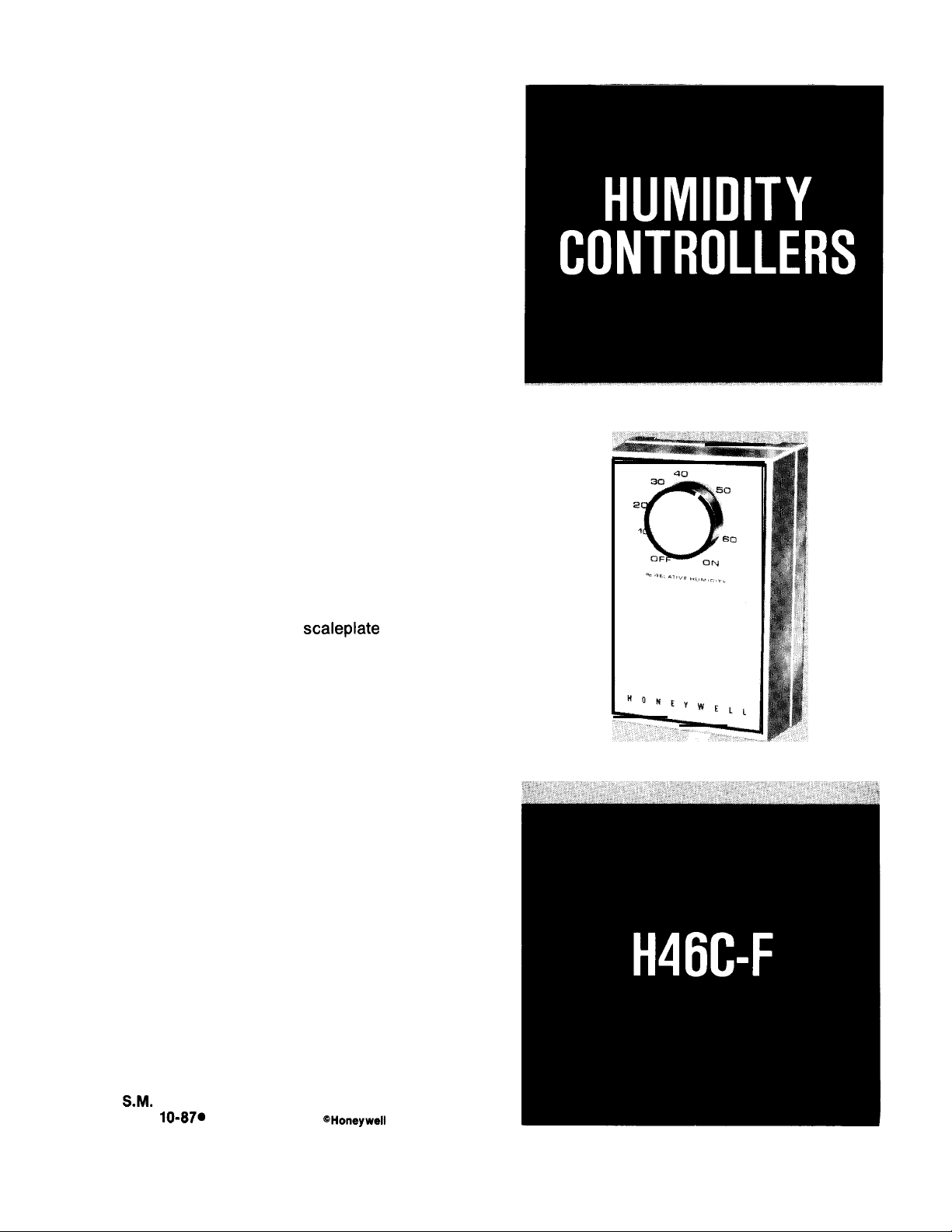
THESE HUMIDITY CONTROLLERS PROVIDE AUTOMATIC CONTROL OF A HU-
MIDIFIER OR A DEHUMIDIFIER FOR DE-
HUMIDIFICATION AND MILDEW CONTROL IN AIR CONDITIONING SYSTEMS.
ALL MODELS ARE SUPPLIED WITH COVER AND CONTROL KNOB FOR WALL
MOUNTING.
❑ Cover of impact-resistant, molded
plastic.
❑ Sensing element of thin, moisture sensi-
tive nylon ribbon provides reliable operation even when ambient temperature conditions change.
❑ Fully enclosed, dust-free, spst, snap
switch.
❑ Large, easy-to-read scaleplate on face
of controller.
❑ Positive ON and OFF setting positions
permit manual operation of the controlled
equipment.
S.M.
REV.
1O-87O
Form Number
@Honeywell
60-2097—2
Inc. 1987
Page 2
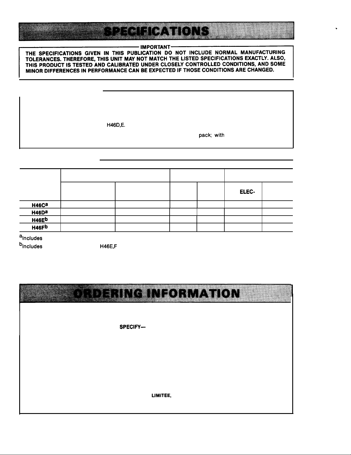
THE SPECIFICATIONS GIVEN IN THIS PUBLICATION DO NOT INCLUDE NORMAL MANUFACTURING
TOLERANCES. THEREFORE, THIS UNIT MAY NOT MATCH THE LISTED SPECIFICATIONS EXACTLY. ALSO,
THIS PRODUCT IS TESTED AND CALIBRATED UNDER CLOSELY CONTROLLED CONDITIONS, AND SOME
MINOR DIFFERENCES IN PERFORMANCE CAN BE EXPECTED IF THOSE CONDITIONS ARE CHANGED.
r’MpORTANT-
TRADELINE MODELS
TRADELINE models are selected and packaged to provide ease of stocking, ease of handling, and maximum
replacement value. TRADELINE model specifications are the same as those of standard models except as
noted below:
.
TRADELINE MODELS AVAILABLE
ADDITIONAL FEATURES:
● H46E includes interrupter plug.
H46D,E.
STANDARD MODELS
SYSTEM CONTROL
HUMIDIFIER LEADWIRE
DEHUMIDIFIER
MODELS
H46Ca
H46Da
H46Eb
H46Fb
alncludes adapter plate for vertical switch box mounting.
blncludes 6 ft [1.8 m] electric cord.
(makes at set point)
x
—
x
—
H46E,F
(makes at set point
less differential)
—
x
—
x
have interrupter plug.
● TRADELINE
special instruction sheet.
SCALE RANGE
20-80%
x
—
x
.
pack; with
(RH) TERMINAL CONNECTION
10-60%
—
x x
—
x
cross reference label and
TYPE OF
OR
ELEC- SCREW
TRIC CORD TYPE
x
Note b
Note b
(continued on page 3)
—
—
—
—
WHEN PURCHASING REPLACEMENT AND MODERNIZATION PRODUCTS FROM YOUR TRADELINE
WHOLESALER OR YOUR DISTRIBUTOR, REFER TO THE TRADELINE CATALOG OR PRICE SHEETS FOR
COMPLETE ORDERING NUMBER, OR
1. Order number, TRADELINE if desired.
IF YOU HAVE ADDITIONAL QUESTIONS, NEED FURTHER INFORMATION, OR WOULD LIKE TO COMMENT ON OUR
PRODUCTS OR SERVICES, PLEASE WRITE OR PHONE
1. YOUR LOCAL HONEYWELL RESIDENTIAL SALES OFFICE (CHECK WHITE PAGES OF YOUR PHONE DIRECTORY).
2. RESIDENTIAL DIVISION CUSTOMER SERVICE
HONEYWELL INC., 1885 DOUGLAS DRIVE NORTH
MINNEAPOLIS, MINNESOTA 55422-4386 (61 2) 542-7500
IN CANADA—HONEYWELL LIMITED/HONEYWELL
Ml P 2V9. INTERNATIONAL SALES AND SERVICE OFFICES IN ALL PRINCIPAL CITIES OF THE WORLD.
SPECIFY—
LIMITEE,
2
740 ELLESMERE ROAD, SCARBOROUGH, ONTARIO
Page 3

ELECTRICAL RATING (A at 50 or 60 Hz):
~74,61 _
H46C,E—
_2&
+
16
‘n
[37.
15
;
[6.4
‘Ir
H46D,F—
H46D,Fa
120 Vac 240 Vac
Full Load
Locked Rotor
Resistive
Pilot Duty
a
H46F model available with 8 or 12 A resistive rating
at 120 Vat.
SET POINT ADJUSTMENT: Control knob on face of
controller.
SWITCHING: Enclosed, dust-proof, snap-acting, spst
switch.
SENSING ELEMENT: Nylon ribbon.
DIFFERENTIAL Nonadjustable, 5 * 1 percent RH.
MAXIMUM AM BlENT TEMPERATURE: 125° F [52° C].
MOUNTING MEANS:
H46C, D—Mounts on vertical switch box with
adapter plate.
H46E,F—Mounts directly on wall with two screws
through keyhole slots in back of case.
COVER DIMENSIONS: See Figs. 1 and 2.
COVER FINISH: Silver bronze.
COVER MATERIAL Molded plastic.
UNDERWRITERS LABORATORIES, INC., LISTED: File
No. E4436; Guide No. XAPX.
CANADIAN STANDARDS ASSOCIATION LISTED: File
No. 1620; Guide No. 400E0.
4.4
26.4
12.0
50 VA at 24
H46D
2.2
13.2
6.0
Vac
h
+—
FIG. lANSTALLATION DIMENSIONS IN in. [mm II
BRACKETS] FOR
7
T
3:
[82.6]
A
J
:
[13.5]
~2J
32
[118.3]
H46C,D.
1
-i
[12.7]
1
,
I
3194A
- 1:
[34.9]
7
II
II
—
IG.
2-INSTALLATION DIMENSIONS IN in. [mm IN
BRACKETS] FOR
H46E,F.
3193A
WHEN INSTALLING THIS PRODUCT. . .
1. Read these instructions carefully. Failure to follow
them could damage the product or cause a hazardous
condition.
2. Check the ratings given in the instructions and on
the product to make sure the product is suitable for
your application.
3. Installer must be a trained, experienced service
technician.
4. After installation is complete, check out product
operation as provided in these instructions.
Disconnect power supply before beginning installation to prevent electrical shock or equipment
damage.
MOUNTING
Follow manufacturer’s instructions, if available. Otherwise proceed as follows. The H46C,D,E,F mount on a
wall at a location that will best sense the relative
humidity of the room. The H46C and D models must be
mounted with the adapter plate on a vertical switch
box. H46E and F models mount with two screws in
keyhole slots in back of case.
WIRING
All wiring must comply with local codes and
ordinances.
FOR MILDEW CONTROL
AND DEHUMIDIFICATION
d
Vacation homes that are unoccupied during the hot,
humid Florida summer are an invitation to mildew. The
3
60-2097—2
Page 4

common cure is to simply select a moderate thermostat
setting and let the air conditioner run. By applying
either a low voltage thermostat in combination with an
H46C
Dehumidistat or a W884E Comfort Center, mildew equipment. This independent operation will allow the
can be reliably prevented and air conditioning energy
use can be oDtimized. The dehumidistat and thermostat
should be
w“ired
in parallel such that by leaving the
system switch in COOL and selecting appropriate set
points for example, 85° F [29° C] and 50 percent RH,
either device will be able to control the air conditioning
higher temperature set point and still prevent mildew by
controlling humidity. For wiring diagrams See Figs. 3
and 4.
Q539A T87F INTERNAL SCHEMATIC
-
~—––-.
I
/+\
FILTER
@
L,~~T
I
I
I
I
I
I
~
~:~&::VERLOADPROTECTIONA
~
HEATING OAMPERMOTOR{IF”SEO,.
~CLOGGED
10,763
FIL7ERSWITCH OR
q,
~,
\
NOD
ISCONNECTMEANSAS
COOLING
PANEL CONNECTION.
HEAT OFF COOL
A “
i J$
B
HEAT oFF COOL
‘----:
&v&
o
w
I
HEATING ‘
RELAY
OR
VALVE
COIL
I
“ ,
Y
.
COOLING
CONTACTOR
COIL
I
FAN
RELAY
COIL
1
1
)
I
4
I
?
r’+
A
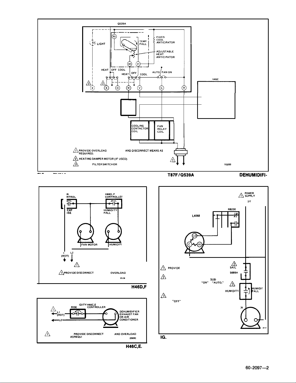
FIG. 3—TYPICAL PARALLEL WIRING DIAGRAM OF H46C WITH T67F/Q539A COMBINATION FOR DEHUMIDIFI-
CATION AND MILDEW CONTROL.
Page 5
~—–––-
1
;
/ \ FILTER
@ L,(-jl+T
Q539A
T87F INTERNAL SCHEMATIC
.- —.-———
T87F
1
I_’
HEATING
RELAY
OR
VALVE
COIL
I
t
~ ~~&~~RLOAO
~ I+EAT,NG DAMPER MOTOR
~
CLOGGED FILTER
—.—
FIG. 4—TYPICAL SERIES WIRING DIAGRAM OF H46C WITH
—--—.—
PrOteCtiOn ANfJ015c0NNEcTh4EAN5.S
{,FUSEO,.
S.WITCH OR
COOLING PANEL CONNECTION.
1
i
CATION AND MILDEW CONTROL.
1
H460,
NTROL CONTROLLER
T
[
EMP
IISE
w
F
HUMIDITY
FALL
1
A
f?
T67F/Q539A
R
H
COMBINATION FOR
FAN CONTROL
L4068
FAN MOTOR
1
.
10,830
COOLING
RELAY
R8230
+F
DEHUMIDIFI-
L
J+
-
–
FAN MOTOR
Q@
L
(1
(’J
POWER ,
A
SUPPLY
&OVIOEDISCONNECT
PROTECTION AS REQUIRE”.
MEANS AND OVERLOAD
HUMIDIFIER
,,,2.
IG. 5—TYPICAL WIRING DIAGRAMS FOR
SINGLE-SPEED FAN MOTOR.
HUM
IOITY H46C,E
~~-~EN
~
POWER SUPPLY,
PROTECTION AS REQUI RED.
FIG. 6—TYPICAL WIRING DIAGRAM FOR
PROVlDEDlSCOt4NECT
MEANS ANC10VERLOAD
H46C,E.
H46D,F
2569C
I
I
I
PROVIOE DISCONNECT MEANS ANO
A
OVERLOAD PROTECTION AS REQUIRE”.
TO ENSURE HUMIDIFIER OPERATION
A
IN WINTER WHEN THERMOSTAT
BASE FAN SWITCH Is AT
ADD SAIL SWITCH TO SYSTEM
AS SHOWN.
TO PREVENT HUMIDIFIER OPERATION
A
IN SUMMER, TURN H460 KNOB
.,
OFF’, PoSITION,
TO
IG.
7—TYPICAL WIRING DIAGRAM FOR H46D IN
‘oON,<
OR
SUB.
‘*AUTO:,
,AJ
SWITCH
S688A -3-
A
H46D
HUMIOITY
CONTROL
HUMIDIFIER
MOTOR
r
Q
2,,4
FORCED AIR SYSTEM WITH 2-SPEED FAN
MOTOR.
5
Page 6

H46D
w-
5WL+ E%@
~ F&~~~l~~S;ONNECT
‘“i’
MEAN, AND
UMIDIFIER
r
CIVERLOAD PROTECTION
251
A
&EH”M,D,FIEFI PLUG ON
~7Ci
DEHUMIDIFIER ON H46E;TOH”M,D,F,ERON
IB
H46E;H”M,D,F,ER PLuG oN
Ii,,,.
“46,
12,444
FIG. 8—TYPICAL WIRING DIAGRAM FOR H48D USED
WITH A SWITCHING RELAY.
H46C & E DEHUMIDIFY
CONTROLLERS
The H46C and E switches make contact on a relative
humidity rise to the set point to start the dehumidifier. A
decrease in relative humidity to the set point minus the
differential breaks the switch contact to
humidifier.
Turn the control knob clockwise
stop to put the dehumidifier in the ON position. Set to
the OFF position by turning the control knob counterclockwise
n
to the stop.
stop the de-
m
to the setting
H46D & F HUMIDITY
CONTROLLERS
The H46D and F switches make contact on a
humidity fall to the set point minus the differential. In
FIG.
9-H46E,F
most humidifier systems, the furnace fan must be
operating before the humidifier starts. An increase in
humidity to the set point breaks the switch contacts.
Turn control knob clockwise
ON position. Set to the OFF position by turning the
control knob counterclockwise
INTERRUPTER PLUG CONNECTIONS.
n
to the stop for
n
to the stop.
CHECKOUT
Place the system in operation and observe through at
least one complete cycle to make certain that all components are functioning properly.
Honeywell Inc.
1885 Douglas Drive N.
Golden Vallay, MN 55422 -4SS8
International Sales Offices in all principal cities of the world. Manufacturing in
Australia, Canada, Finland, France, Germany, Japan, Mexico, Netherlands,
Spain, Taiwan, United Kingdom, U.S.A.
PRINTED
IN U.S.A.
Im
QUU2TYLSKEY
e
 Loading...