

Honeywell GK DATASHEET
Solenoid valves I 21
GK series
for neutral media up to 180°C
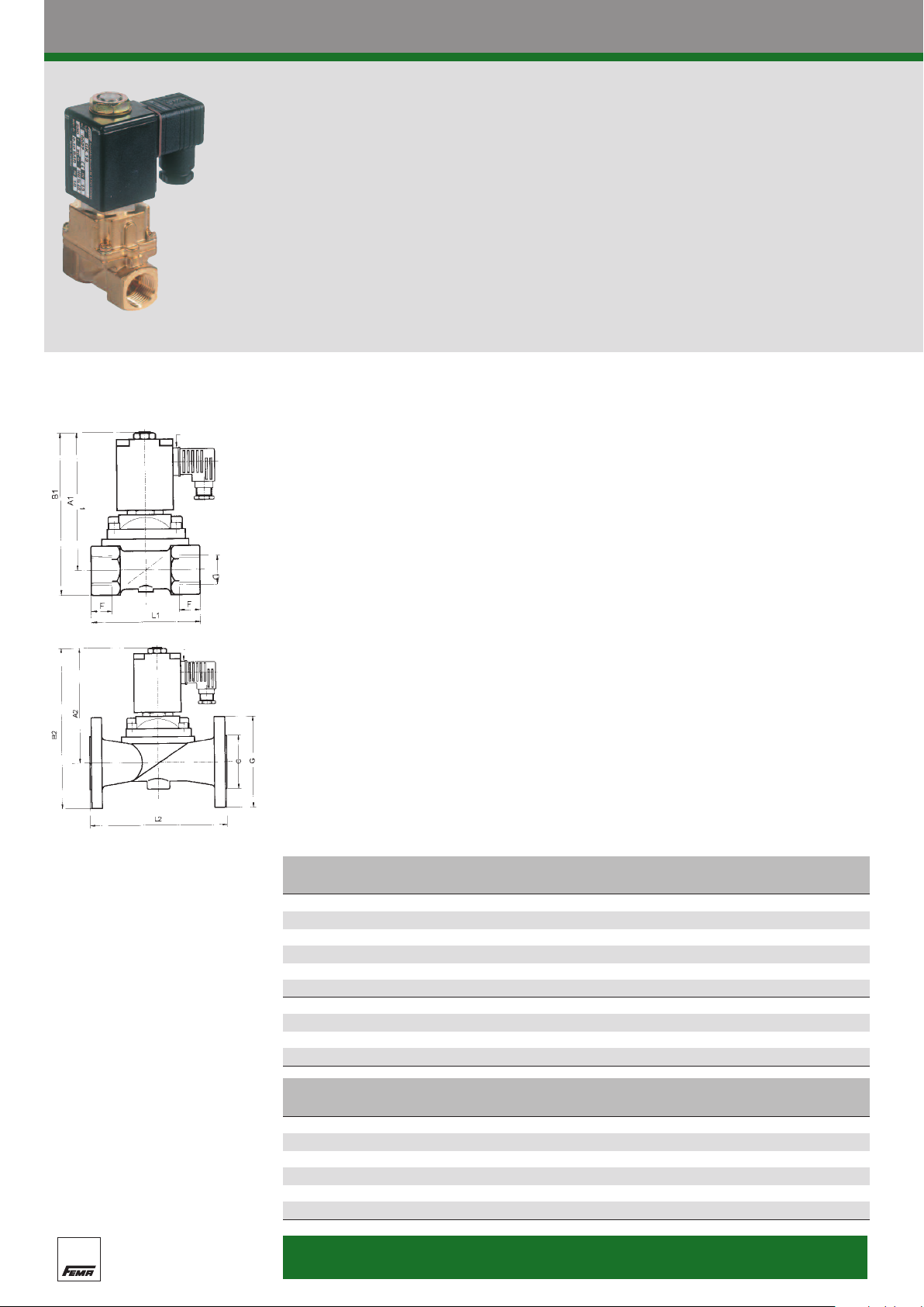
Dimensioned drawings
Shown turned
hrough 90°
t
Shown turned
through 90°
The GK series piston-type solenoid valves are
ideal for use as shutoff valves in heating and
process engineering systems for neutral media
no minimum differential pressure and can open
and close even without pressure or with low
differential pressures.
such as hot water and steam. The valves require
Technical data
Type
2/2-way
Operating mode normally closed
Type of construction Piston-type solenoid valve, coupled, no minimum differential
pressure required.
Materials Scr
ewed version: brass; flange version: cast iron GG 25.
Sealing material PTFE and graphite
Media Neutral media, e. g. hot water and steam.
emperature of medium
T
°C to 180°C
0
Ambient temperature max. 55°C
Viscosity max. 21 mm2/s
Line connection G 1 to G 2, flange for DN 25—DN 50
Operating voltages (±10%) 230 V, 50 Hz
Special voltages available Voltage Code
110 VAC 2
24 VAC 8
For example: GK 20–2 (2 = 110 VAC)
Duty cycle 100%
Electrical connection Angled plug to DIN 43 650
Power consumption Start: 100 VA; operation: 35 VA, DN 50: 30 W
ee of protection
Degr
IP 65
Mounting position Any, solenoid actuator preferably upwards
Switching times opening: DN 15—DN 25: 100—400 ms
(standard values) DN 32—DN 50: 200—1200 ms
closing: DN 15—DN 25: 300—500 ms
DN 32—DN 50: 1000—3000 ms
k
(m
vs
3
y
value
/h)
orking
W
Connection
Material Weight Type
pressure (bar) (kg)
oduct Summar
Pr
DN
(mm)
13 3.7 0–10 G 1/2“ Brass 1.0 GK 13
20 5.0 0–10 G 3/4“ Brass 1.4 GK 20
25 10.0 0–10 G 1“ Brass 1.9 GK 25
32
16.0 0–10 G 1 1/4“ Brass 3.2 GK 32
40 16.0 0–10 G 1 1/2“ Brass 3.7 GK 40
50 36.0 0–10 G 2“ Brass 7.8 GK 50
25 10.0 0–10 Flange GG 25 4.6 GK 25 F
32
16.0
0–10
Flange GG 25 7.0 GK 32 F
40 16.0 0–10 Flange GG 25 7.5 GK 40 F
50 36.0 0–10 Flange GG 25 12.8 GK 50 F
Screwed versions Flange versions
DN
13
D L1 A1 B1 F C G L2 A2 B2
113
1/2“
G
65
127
14
20 G 3/4“ 100 131 147 16
25 G 1/2“ 115 136.5 157 18 68 120 160 140.5 210.5
161 186 20 78 140 180 161 231
32
G
1 1/4“
126
40 G 1 1/2“ 126 165 195 22 88 150 200 165 240
50 G 2“ 164 225 260 24 102 165 230 225 307.5
s
Degree of protection:
IP 65
 Loading...