

Page 1

FBII CP-220A
Central Station Receiver
Hookup and Installation Instructions
N9624V1 Rev. B 8/98
Page 2

Table of Contents
CP-220 Central Station Receiver
Hookup and Installation Manual
Section 1: Getting Acquainted
To the New Operator ................................................................................................... 1-1
What Is a Central Station Digital Receiver? ................................................................. 1-1
Digital Communicators and Communication Formats................................................... 1-2
A Close Look at the CP-220......................................................................................... 1-5
Gaining Access ................................................................................................ 1-6
Inspecting the CP-220...................................................................................... 1-7
Removing the Line Card Retaining Bar ............................................................ 1-8
Removing Cards in the CP-220 ........................................................................1-8
Obtaining Your Access Code ........................................................................... 1-8
Replacing Cards in the CP-220 ........................................................................ 1-8
The Front Panel of the CP-220 .................................................................................... 1-9
The Rear Panel of the CP-220................................................................................... 1-11
What Is Programming? .............................................................................................. 1-15
Preparing for Programming........................................................................................ 1-16
Programming With No External Connections.................................................. 1-16
Programming After External Connections Have Been Made .......................... 1-17
Section 2: Programming the CP-220 Receiver
Introduction..................................................................................................................2-1
Preparation for Programming:
No External Connections Made........................................................................ 2-1
Preparation for Programming:
External Connections Have Been Made........................................................... 2-4
Entering and Using the Programming Mode ................................................................ 2-5
Category A: Receiver Operation2-7
PARAMETER 03: Receiver Number................................................................2-8
CP-220A Central Station Receiver Section 1: Getting Acquainted Page i
Hook-Up and Installation Manual
Page 3

Category A: Receiver Operation Continued
PARAMETER 04: Sounder.............................................................................. 2-9
PARAMETER 05: Group Number.................................................................. 2-10
PARAMETER 06: Ring Signal....................................................................... 2-12
PARAMETER 07: Handshake....................................................................... 2-14
PARAMETER 08: Handshake Delay ............................................................. 2-16
PARAMETER 26: Set Time........................................................................... 2-18
PARAMETER 28: Slot English Language...................................................... 2-19
Samples: 3 + 1 Standard Format
Receiving Line Card Programmed for "Slot English Language"............. 2-23
Samples: 4 + 1 Standard Format
Receiving Line Card Programmed for "Slot English Language"............. 2-23
Samples: 3 + 1 Expanded Format
Samples: 4 + 1 Expanded Format
Receiving Line Card Programmed for "Slot English Language"............. 2-24
Samples: 4 + 2 Format
Receiving Line Card Programmed for "Slot English Language"............. 2-26
PARAMETER 29: Copy Slot.......................................................................... 2-27
PARAMETER 30: Slot English On/Off........................................................... 2-28
PARAMETER 27: Channel English ............................................................... 2-30
PARAMETER 31: Operator Log On............................................................... 2-32
PARAMETER 32: Listen-In Time................................................................... 2-34
PARAMETER 33: Listen-In Accounts............................................................ 2-36
PARAMETER 36: Battery Test...................................................................... 2-37
PARAMETER 37: Manual Turnoff of Sounder............................................... 2-38
PARAMETER 40: Automatic Mode Enable.................................................... 2-39
PARAMETER 42: Line Fault Detector ........................................................... 2-41
PARAMETER 44: 3x1 With Parity ................................................................. 2-42
PARAMETER 47: FBI English....................................................................... 2-44
PARAMETER 55: FBI Superfast/LAR300...................................................... 2-47
PARAMETER 56: Handshake Duration......................................................... 2-49
PARAMETER 57: Auto Mode Sounder On/Off .............................................. 2-50
PARAMETER 58: Format Date ..................................................................... 2-52
PARAMETER 59: 4x2 With Parity ................................................................. 2-53
PARAMETER 60: 4x1 With Parity ................................................................. 2-55
Page ii Section 1: Getting Acquainted CP-220A Central Station Receiver
Hook-Up and Installation Manual
Page 4

PARAMETER 61: Extended BFSK Alarms.................................................... 2-57
PARAMETER 61: Extended BFSK Alarms.................................................... 2-57
PARAMETER 62: Programmable Handshakes ............................................. 2-59
Category B: Printer Operation
PARAMETER 01: Printer I/O......................................................................... 2-64
PARAMETER 35: Printer Line Feed.............................................................. 2-65
PARAMETER 38: Printer Fail/Manual ........................................................... 2-67
PARAMETER 41: Message Spaces.............................................................. 2-68
PARAMETER 34: Test Character.................................................................. 2-71
PARAMETER 43: Auto Message .................................................................. 2-72
Category C: Computer Operation
PARAMETER 00: Computer I/O.................................................................... 2-75
PARAMETER 02: Receiver Computer Type.................................................. 2-76
PARAMETER 09: Serial Baud....................................................................... 2-77
PARAMETER 10: Serial Stop Bits................................................................. 2-78
PARAMETER 11: Serial Data Bits................................................................. 2-79
PARAMETER 12: Header ............................................................................. 2-80
PARAMETER 15: Computer Trouble Delay................................................... 2-81
PARAMETER 16: ACK.................................................................................. 2-82
PARAMETER 17: NAK.................................................................................. 2-83
PARAMETER 18: BS .................................................................................... 2-85
PARAMETER 19: CR.................................................................................... 2-85
PARAMETER 13: Time................................................................................. 2-86
PARAMETER 14: T-Header .......................................................................... 2-87
PARAMETER 20: DTR.................................................................................. 2-88
PARAMETER 21: RTS.................................................................................. 2-89
PARAMETER 22: Terminator........................................................................ 2-90
PARAMETER 23: Time Terminator............................................................... 2-91
PARAMETER 24: LF..................................................................................... 2-92
PARAMETER 25: Clock Set.......................................................................... 2-93
CP-220A Central Station Receiver Section 1: Getting Acquainted Page iii
Hook-Up and Installation Manual
Page 5

PARAMETER 39: Computer Fail/Manual ...................................................... 2-94
PARAMETER 45: Data Loop Test................................................................. 2-95
PARAMETER 46: Computer Fail Test........................................................... 2-96
PARAMETER 51: XON ................................................................................. 2-97
PARAMETER 52: XOFF................................................................................ 2-99
PARAMETER 53: Acron 11-Digit With Zero or Space ................................. 2-100
PARAMETER 54: RTS/CTS Protocol (On/Off) ............................................ 2-101
Operating Notes......................................................................................................2-103
Automatic Mode/Manual Mode ................................................................................ 2-103
Appendix A: Understanding Binary and Hexadecimal Numbering Systems........ A-1
Appendix B: Communication Formats ....................................................................B-1
Index ..............................................................................................................................I-I
Page iv Section 1: Getting Acquainted CP-220A Central Station Receiver
Hook-Up and Installation Manual
Page 6

Obtaining the Access Code Used
With Your CP-220A
Remove This Page From the Manual for Security
Purposes and Store It for Safekeeping!
Every CP-220A Digital Alarm Receiver is furnished with a unique four-digit
Access Code that is required to configure, or program, the unit so that it
conforms to the needs of your Central Station. The Access Code should be
available only to those individuals who have the responsibility of maintaining
and updating the CP-220A.
The Access Code is found in two locations: one on, and one within, the
receiver. After reading the following information, please make note of this
4-digit code in the spaces provided below and, for safekeeping and security
purposes, remove and store this page away from the receiver. The Access
Code, as found in each of the two locations, is identical.
Location 1: On the Rear Panel
The Access Code is the first four digits of the CP-220A's Serial Number,
which can be found on the right side of the rear panel. See Figure 1-6 on page
1-11.
Location 2: On the REC-20 Main CPU Card
a) Slot 11 (corresponding to J11) within the receiver contains its Main
CPU Card, part number REC-20. Carefully withdraw this card by
following the instructions on page 1-8.
b) On the card, locate the “chip” designated as U13 (marked in tiny
letters on the card), which is at the top middle of the board. The
four-digit Access Code will be written on the label affixed to the
chip.
c) Carefully replace the REC-20 board in the J11 slot.
Record the Access Code in these 4 spaces and store it in a safe place:
Page 7

Section 1
r
n
r
d
h
f
Getting Acquainted
To the New
Operator
What Is a
Central Station
Digital
Receiver?
Working in a Central Station can be a rather imposing responsibility. To a
newcomer, the busy atmosphere, along with the electronic equipment,
computer screens, and telephone consoles may seem very imposing. Beneath
it all lies the primary purpose of the Central Station: to help protect the life
and property of its commercial and residential customers, people who have
security systems installed in their businesses or homes. Central Stations
also provide other functions for their subscribers, which will become
apparent as you get better acquainted with your responsibilities. Eithe
way, you can be proud that you are associated with an organizatio
dedicated to the safety and security of its customers. In your role as an
operator or dispatcher, you will no doubt make an important contribution to
that cause.
This manual has been written to help to acquaint you with one of the majo
elements in your Central Station's operation—the FBI CP-220A Central
Station Digital Receiver.
A Central Station Digital Receiver is a key piece of equipment found in
virtually all Central Stations. It is designed to receive information about the
events detected by the security system in the premises of the Central
Station's customers. Such events may have a bearing on the customer's
well-being, the security of the premises, and even the operation of the alarm
system itself.
The transmission of information to the Central Station is normally initiate
as a telephone call by the security system at the customer's premises and
carried over the regular telephone network to the Digital Receiver at the
Central Station. Once the Receiver answers the call, electronically encoded
information related to the customer's account is communicated. Once suc
messages have been checked for accuracy and are determined to be
legitimate, the Receiver at Central Station sends a signal back to the
customer's alarm system informing it that its message has been received
and instructing it to "hang up" the line.
Figure 1-1 on the following page summarizes this process and illustrates
how it takes place. The circled numbers in the figure refer to the sequence o
events listed below it.
CP-220A Central Station Receiver Section 1: Getting Acquainted Page 1-1
Hook-Up and Installation Manual
Page 8
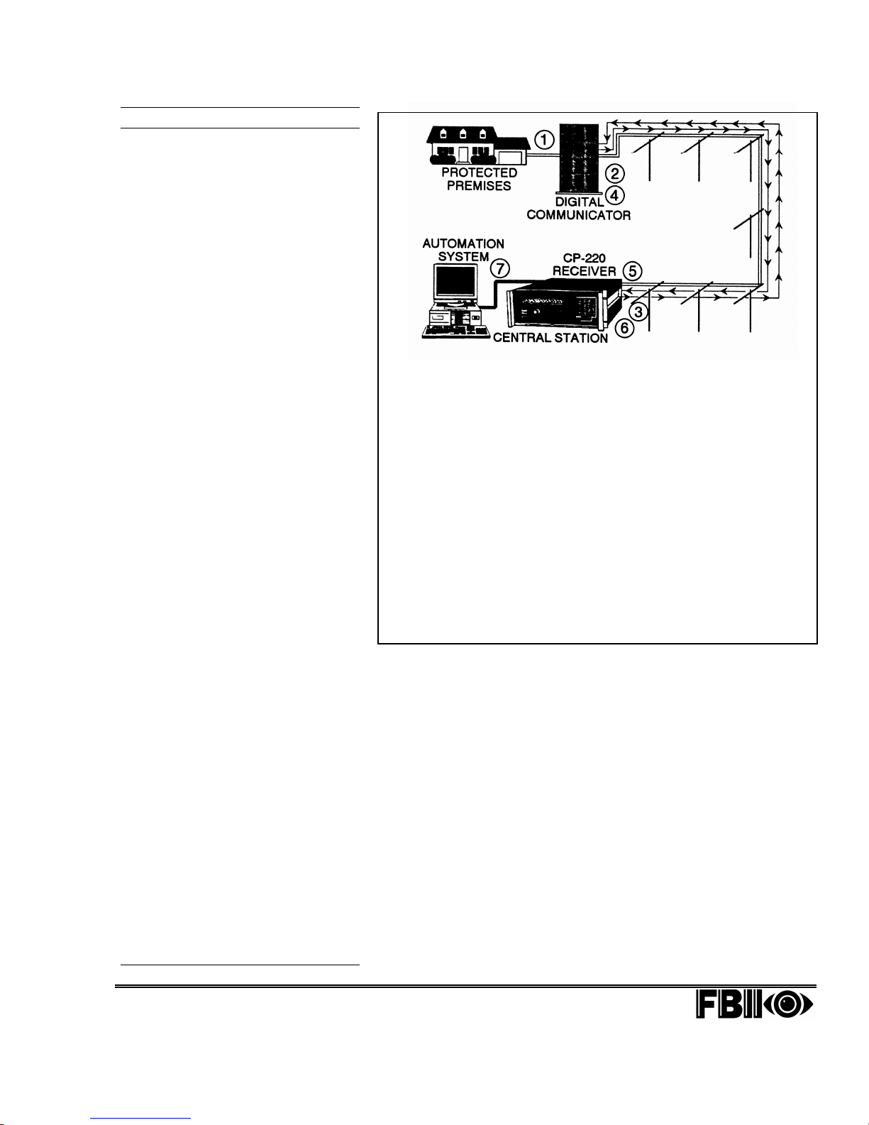
The Communication Process
A Digital Communicator
Digital Dialer
security systems and used to report alarms
and other information – over the standard
telephone network – to Central Station
Receivers, such as the FBI CP-220A.
Typically, when activated by the security
system, its
automatically call one of the phone lines
assigned to the Central Station’s Receiver.
Once the CP-220A senses the telephone
company’s
programmed number of rings, answers the
active phone line, pauses for a preprogrammed time interval, and then causes
the corresponding
programmed
communication from the subscriber’s
premises. At the point that the CP-220A
“picks up” the line, the “On-Line” LED (see
page 1-9) lights, indicating which of the (up to
8)
Phone Lines/Line Card
processing the call.
Once it receives the appropriate handshake,
the Digital Communicator proceeds with the
data transmission. After the CP-220A
the data (see
appropriate
communicator to shut down unless there is
more data to be communicated. In such
cases, additional “rounds” of data and
subsequent
Kissoff
final
line and passes the data on to its display
and/or to any peripheral device(s) to which it
may be connected.
Note that each of the
to 12 subscriber phone calls in the event that
multiple Line Cards are accepting data at the
same time. All incoming data is processed on
first come, first served
a
Because such information is in “raw” form and
must be interpreted, most Central Stations
employ an
means of a computer, uses this data to access
a customer Database that converts such “raw”
information into a readable format that can be
easily understood and acted upon by the
Central Station’s operators.
Each CP-220A provides an
Manual
In the
not
will
be passed on to an attached
Automation System
operated in
display all the data it receives, but requires
operator intervention.
The CP-220A can be programmed to display
English Language
page 2-19), including the subscriber’s
Number
various alarm and trouble conditions.
) is a device incorporated into
Digital Communicator
ring signal
handshake
Appendix B
Kissoff
Kissoff
, the CP-220A releases the phone
Automation System,
mode of operation (see page 2-103).
Automatic Mode
be displayed by the receiver, but will
its Manual Mode
and the wording used to represent
(also known as a
will
, it waits for the pre-
Line Card
tones may occur. After the
(see below) if it exists. If
(see
to deliver a pre-
tone(s), which invites
combinations is
), it delivers the
tone, causing the
Line Cards
basis.
Automatic
, the transmitted data
, the CP-220A
PARAMETER 28
verifies
can stack up
which, through
and a
Printer
and/or
will
on
Account
Figure 1-1 Communication… In a Nutshell
1. An alarm occurs at the
protected premises.
2. Moments later, the Security
5. When received at the Central
System’s Digital Communicator
(which is connected to the
telephone network) goes “offhook” and automatically dials
6. If found to be “legitimate,” the
the phone number of the Digital
Receiver at the Central Station
(with which it has been
programmed).
7. If the Central Station has a
3. When the Digital Receiver
answers the call, it produces a
“Handshake” tone that invites
the Digital Communicator to
transmit the alarm (or other
information),
4. Once the “Handshake” is
Digital Communicators and
Communication Formats
Unfortunately, manufacturers of security equipment have
not always been able to agree on the best way to
communicate data between a protected premises and a
Central Station. As a result, a variety of different
communication formats or "protocols" have emerged
claiming to have particular distinctions or advantages over
the others. To be effective, the CP-220A Digital Receiver
must be able to process communications from a wide range
of security products produced by many different
manufacturers. Fortunately, Digital Receivers like the
CP-220A have the "intelligence" to recognize the different
communication protocols it receives and make the proper
adjustments so it can correctly interpret the data
automatically and transparently to the operator.
Page 1-2 Section 1: Getting Acquainted CP-220A Central Station Receiver
Hook-Up and Installation Manual
received, the communicator
transmits the required data.
Station, the information is checked
for accuracy.
Digital Receiver produces a
“Kissoff” tone that instructs the
Digital Communicator to go “on
hook” and release the line.
computer-based Automation
System, the raw data processed
by the Digital Receiver is utilized
to access a Database and provide
meaningful information to the
Central Station’s operators.
– each
– all
Page 9
While the study of data formats and protocols can get
t
y
rather involved (see Appendix B), a generic discussion of
them is appropriate at this time. Essentially, all formats
deliver common information about the protected premises.
This information includes an account number identifying
the customer from whose premises the report is being
made, as well as information about the nature of the
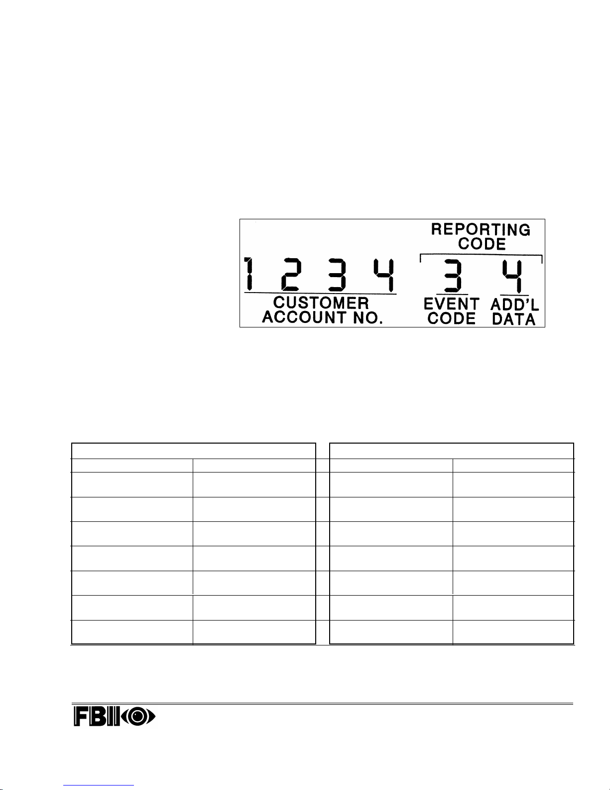
report, seen in Figure 1-2 as the Reporting Code. The
figure provides an example of a popular reporting format
that carries sufficient information for an operator at the
Central Station to properly dispatch the event.
Data delivered to the Central
Station from any of its
Customer Accounts is often
required to convey
substantial amounts of
information in a short period
of time. To do so, many
different methods of carrying
data, called
protocol represented in
Figure 1-2 is quite popular
neither the simplest nor the
express information and has
been chosen to illustrate this
protocols,
been developed. The
and is known as an
Expanded Format
most complex way to
have
. It is
concept.
FIGURE 1-2
The following table contains examples of what each of the two
characters in the above Reporting Code may represent. Note that what
appears in the table is by no means absolute, and the characters
assigned to the particular events are often determined by the
preferences of the individual Central Stations. Also keep in mind tha
the Expanded Format used in this illustration is only one of man
formats that communicate such information.
REPORTING CODE REPORTING CODE
1st CHARACTER 2nd CHARACTER 1st CHARACTER 2nd CHARACTER
1 FIRE 1-9 ZONES 8 ZONE 1-9 ZONES
1-9 TROUBLE 1-9
2 HOLDUP 1-9 ZONES 9 TEST 0 DOESN'T
(SILENT) 1-9 APPLY
3 BURG 1-9 ZONES B OPENING 0-F USERS 0-F
1-9 (PREMISES)
4 MEDICAL 1-9 ZONES C CLOSING 0-F USERS 0-F
EMER 1-9 (PREMISES)
5 PANIC 1-9 ZONES D ABORT 0 DOESN'T
(AUDIBLE) 1-9 SIGNAL APPLY
6 ZONE 1-9 ZONES E ZONE 1-9 ZONES
BYPASS 1-9 RESTORE 1-9
7 ENVIRON 1-9 ZONES F SYSTEM 0-F EVENTS
EMER 1-9 TROUBLE 0-F
Several examples have been furnished on the next page to help clarify the point. For convenience,
the above table has been repeated, as well.
CP-220A Central Station Receiver Section 1: Getting Acquainted Page 1-3
Hook-Up and Installation Manual
TABLE 1-1
Page 10
REPORTING CODE REPORTING CODE
1st CHARACTER 2nd CHARACTER 1st CHARACTER 2nd CHARACTER
1 FIRE 1-9 ZONES 8 ZONE 1-9 ZONES
1-9 TROUBLE 1-9
2 HOLDUP 1-9 ZONES 9 TEST 0 DOESN'T
(SILENT) 1-9 APPLY
3 BURG 1-9 ZONES B OPENING 0-F USERS 0-F
1-9 (PREMISES)
4 MEDICAL 1-9 ZONES C CLOSING 0-F USERS 0-F
EMER 1-9 (PREMISES)
5 PANIC 1-9 ZONES D ABORT 0 DOESN'T
(AUDIBLE) 1-9 SIGNAL APPLY
6 ZONE 1-9 ZONES E ZONE 1-9 ZONES
BYPASS 1-9 RESTORE 1-9
7 ENVIRON 1-9 ZONES F SYSTEM 0-F EVENTS
EMER 1-9 TROUBLE 0-F
TABLE 1-1
EXAMPLES:
FULL
MESSAGE
1234 32 1234 32 a BURGLAR ALARM has occurred due to the violation of
2412 81 2412 81 a TROUBLE (e.g., a wiring fault) has been detected on
1867 9 1867 9 a TEST REPORT has been initiated at the protected
1234 E2 1234 E2 a previously reported violation of Zone 2 has been
4657 69 4657 69 the security system was armed with its Zone 9 bypassed
CUSTOMER
ACCT NO.
REPORTING
CODE
MEANING
an alarm sensor on Zone 2
Zone 1, which may compromise its integrity
premises
restored to normal
769 C 769 C an employee of Customer Account 7609, assigned to
USER CODE, has closed the premises by arming the
system
2232 F1 2232 F1 a SYSTEM TROUBLE (e.g., a loss of AC Power or a Low
Battery) has occurred in the security equipment
6574 D 6574 D an ALARM, likely to be caused in error, was cancelled by
the user shortly after it was initiated
769 B1 769 B1 an employee of Customer Account 7609, assigned to
USER CODE 1, has opened the premises by disarming
the system
NOTE: The characters "B" through "F" are used to increase the number of variations capable of being
reported by most communication formats, when compared to those using only the digits between "0" and "9."
Using such "alpha" characters in designating numbers is characteristic of a numbering system known as
hexadecimal, which is often used in computers and discussed in Appendix A. Note, too, that for technical
reasons, hexadecimal "A" is not used in many alarm communication formats. See Appendix B for additional
information.
Page 1-4 Section 1: Getting Acquainted CP-220A Central Station Receiver
Hook-Up and Installation Manual
Page 11

A Close Look at
t
y
y
n
a
g
A
n
y
the CP-220A
FBI's CP-220A Digital Alarm Receiver is a state-of-the-art device tha
supports almost all Communication Formats currently used in the securit
industry. With the proper equipment, the CP-220A can simultaneousl
process data from up to 8 telephone lines, creating maximum throughput i
busy Central Stations. The CP-220A is capable of:
•accepting most communication formats on the same Line Card (see
Line Cards on page 1-7)
•monitoring up to 400,000 accounts with 8 Line Cards in use
•storing up to 26 signals per Line Card if receiver activity prevents
immediate message display
•detecting faults on each of the telephone lines in use
•outputing all incoming signals and system messages on
40-character fluorescent display
•producing different English language messages for each Line Card
installed
•configuration programming via its front panel keypad
•"Listen-In" capability (see Listen-In on page 2-34)
•monitoring proprietary accounts without the need for telephone lines
The CP-220A has several basic but primary responsibilities:
•to process the data representing alarm (or supervisory, trouble, or
test) conditions generated by the security systems belonging to the
Central Station's customers
•to display (and optionally print) this data in the format in which it
was sent, along with a short English Language description of the
event, if so programmed
•to pass the data on to an Automation System (if available) where it
can be automatically interpreted for use by the Central Station's
operators
The CP-220A has been designed for either desktop use or for rack mountin
− convenient in the event that more than one Central Station Receiver will
be used.
variety of metal cabinets, suitable for one or more Central Statio
Receivers such as the CP-220A, is available from:
Premier Metal, Inc.
381 Canal Place
Bronx, NY 10451
(718) 993-9200
Model No. TVA6119-26 is a cabinet that stands 67¼" high, 22" wide, and 28
" deep. It provides 61¼" usable mounting space and accommodates man
similar pieces of equipment.
Note 1: In order to maintain the UL listing on the FBII CP-220A Receiver,
you must connect the incoming phone lines through an LF-465
Module.
CP-220A Central Station Receiver Section 1: Getting Acquainted Page 1-5
Hook-Up and Installation Manual
Page 12
r
y
NOTE 2: The CP-220A is equipped with a Line Card
Retaining Bar to prevent its replaceable circuit
cards from being dislodged during shipping. If the
CP-220A is to be rack mounted or will otherwise
remain stationary, the Line Card Retaining Ba
can be removed so that Line Cards may be easil
added or replaced, should that be necessary. This
procedure is explained in Step 3 on page 1-8.
Although the CP-220A may seem
imposing to the first-time user, it has
been designed so that its setup and
operation are based on logical steps,
which will be covered in this manual.
FIGURE 1-3
The following steps describe the procedures through which
you can become familiar with your CP-220A and, if desired,
you can remove of the Line Card Retaining Bar.
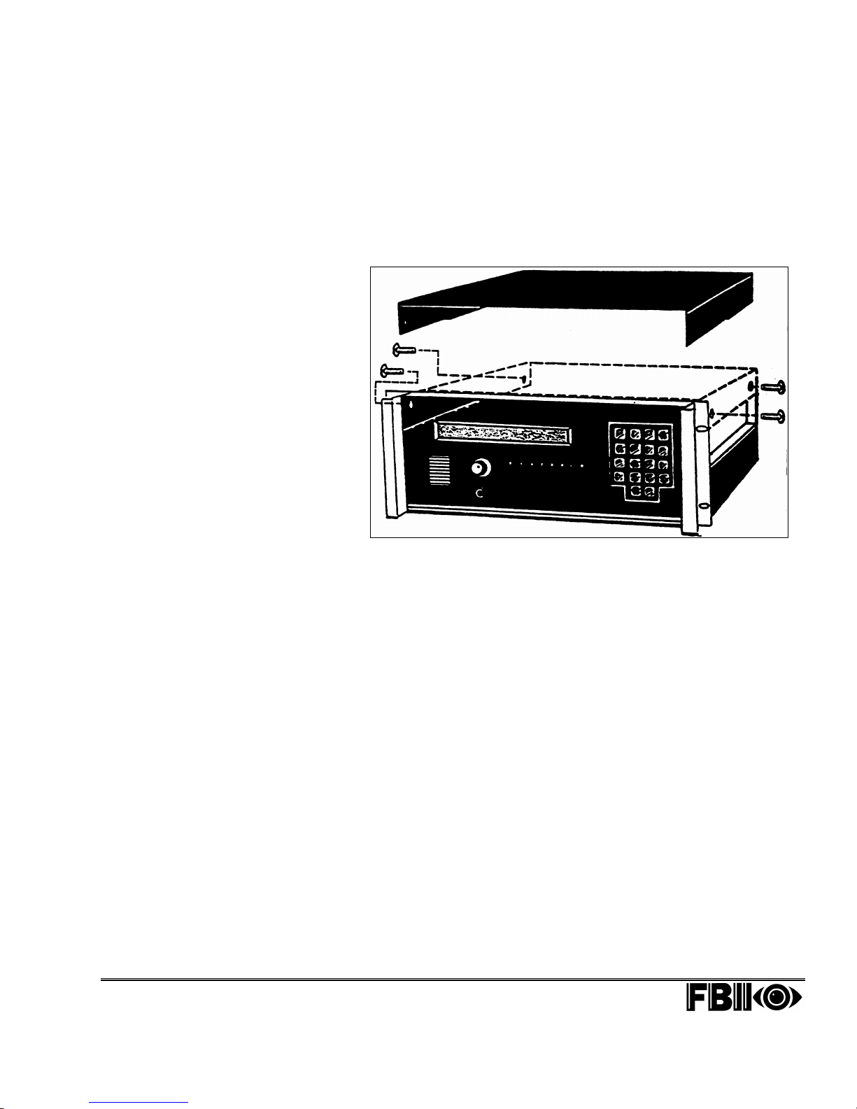
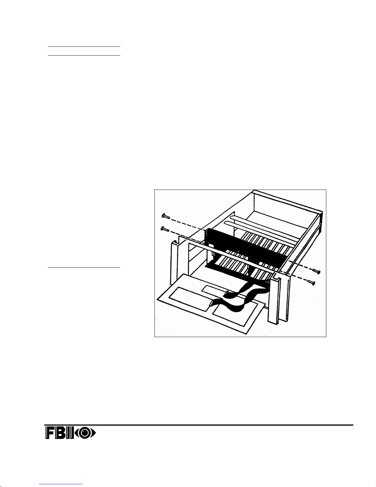
Step 1: Gaining Access
Before beginning, make sure the CP-220A is not connected
to any source of power – whether it be AC or battery.
a) Remove the four mounting screws that secure the top
cover, located on the left and right sides of the unit.
Pull the cover straight up and off. To avoid misplacing
the screws, partially re-thread them into the holes from
which they were removed. See Figure 1-3.
b) Remove the four screws securing the front panel and
lay the panel face down on a soft surface, as shown in
Figure 1-4. Be careful not to scratch the display
window or separate the front panel's ribbon or wired
cables from their connectors. As before, partially
re-thread the front panel's retaining screws into the
holes from which they were removed, to avoid loss.
Page 1-6 Section 1: Getting Acquainted CP-220A Central Station Receiver
Hook-Up and Installation Manual
Page 13
Line Cards
In the CP-220A, each
Line Card
electronic circuit –
contained on a printed
circuit board – which
interfaces between an
incoming phone line and
the processing and
display circuitry in the
receiver. When it
receives a phone call, the
Line Card produces a
handshake
signal for the alarm
system’s Digital
Communicator to begin
sending data. CP-220A
Line Cards are capable of
decoding data from a
wide range of alarm
systems because of their
ability to recognize and
adjust to a variety of
communication protocols.
Currently, all CP-220A’s
are furnished with two
REC-11 Line Cards; up to
six additional REC-11s
can be added.
tone that is a
is an
Step 2: Inspecting the CP-220A
a) Looking directly into the CP-220A from the front, it
should be clear that a number of electronic circuit
boards, or cards, can be installed so that they each
plug into a mating edge connector on a circuit board
located midway between the front and rear of the
CP-220A's housing.
b) Note that such edge connectors are labeled with
designations from J1 through J12. Your CP-220A
should be equipped with several such cards that have
already been plugged into the appropriate connectors.
Among them are at least two Line Cards, either
REC-1 or REC-11: one occupying Slot 1 (corresponding
to J1) and one occupying Slot 8 (corresponding to J8).
Slots 2 through 7 (corresponding to J2 through J7) are
available for additional Line Cards as the need arises.
Opening the CP-220A as
described reveals several
important aspects of the
receiver, which will be
detailed in the following text.
CP-220A Central Station Receiver Section 1: Getting Acquainted Page 1-7
Hook-Up and Installation Manual
FIGURE 1-4
c) Slot 9 (corresponding to J9, for which there is no edge
connector) must always be left blank.
d) Slot 10 (corresponding to J10) contains the receiver's
Jumper Card, known as REC-21.
e) Slot 11 (corresponding to J11) contains the receiver's
Main CPU Card, known as REC-20.
f) Slot 12 (corresponding to J12) contains the receiver's
I/O (Input/Output) Card, known as REC-3.
Page 14

The Retaining Bar:
An Important Note!
Newer versions of the
CP-220A use a
retaining bar that is
integrated into the
receiver’s front panel,
rather than into its
chassis. If your CP220A has this type of
arrangement, it is NOT
necessary to perform
the instructions in Step
3, at the right.
Step 3: Removing the Line Card Retaining Bar
a) Locate the Line Card Retaining Bar, which is the black
bar spanning the top of the twelve card slots. As shown
in Figure 1-4, the bar is held in position by a
screw/lockwasher/nut combination located on each side
of the CP-220A.
b) Removing the bar is optional. Doing so permits easy
access to the CP-220A's Line Cards (occupying Slots 1
through 8) and circuit cards (occupying Slots 10
through 12), should such cards ever need to be added or
replaced. Note that if the bar is to be removed, it must
be replaced if the unit is ever shipped, to avoid possible
damage to the cards in the CP-220A.
c) Carefully loosen and remove each screw/lockwasher/nut
combination supporting the Line Card Retaining Bar.
As before, to avoid loss, re-thread each set of fasteners
into the hole in the CP-220A's chassis from which they
Remember!
While working inside the
CP-220A, all sources of
power (both AC and
Battery Backup) must be
disconnected. Do NOT
remove any Line Cards or
Circuit Cards when power
is applied.
were removed.
d) Keep the Line Card Retaining Bar in a safe place for
future use.
Step 4: Removing Cards in the CP-220A
Once the Line Card Retaining Bar has been removed,
any Line Card or Circuit Card can be withdrawn from
the CP-220A by firmly grasping its white handle, or
card puller, and pulling straight out. Once it has been
removed, handle the card carefully.
Step 5: Obtaining Your Access Code
To properly set up your CP-220A, it will have to be
configured, or programmed, for the operation desired. To
"enter" the programming mode, you will need an Access
Code, unique to your CP-220A. Information on obtaining
this Access Code can be found on the first page of this
manual – a page that should be removed for security
reasons. If you haven't already done so, locate this page
and use the information provided to obtain your Access
Code.
At this point, store the page apart from the manual for
safekeeping. You will have to use the Access Code in
Section 2 when you first "enter" the programming mode.
Page 1-8 Section 1: Getting Acquainted CP-220A Central Station Receiver
Hook-Up and Installation Manual
Page 15
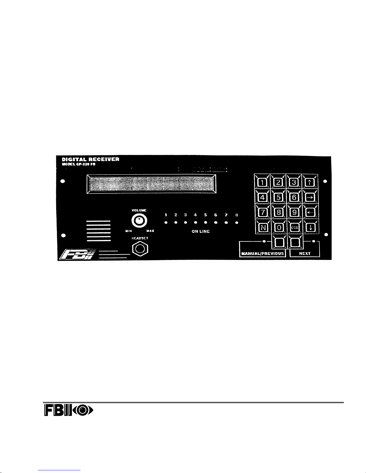
The Front Panel of the
t
y
y
t
t
r
t
g
CP-220A
Step 6: Replacing Cards in the CP-220A
a) When inserting a card, carefully guide it into the
designated slot, being sure that its electronic
components are facing toward the left. Once the card
reaches the edge connector, push it firmly until it snaps
into place.
b) Reinstall the CP-220A's front panel and top cover at this
time by reversing the sequence covered earlier in Step 1.
The front panel of the CP-220A contains all of the controls
and features necessary for an operator at the Central
Station to use the Receiver and interpret the information i
produces.
The front panel of the CP-220A provides a
display that produces all the necessar
information needed by an operator to
process alarm, trouble, and supervisor
messages received from the Central
Station's subscribers. To its right is a keypad
that is used primarily to program the
CP-220A with an operating configuration
desired by the Central Station. On the lef
side of the unit, a loudspeaker, a volume
control, and a headphone jack provide the
operator with the ability to "listen in" to the
activities surrounding the conditions tha
have caused alarms from designated
subscribers. Finally, a series of 8 indicators
(LEDs) correspond to the activities of up to 8
Line Cards placed in the receiver. See the
text for additional details.
CP-220A Central Station Receiver Section 1: Getting Acquainted Page 1-9
Hook-Up and Installation Manual
FIGURE 1-5
Fluorescent Display
Prominent on the face of the CP-220A is a 40-characte
fluorescent display, which, among its other attributes,
furnishes information about alarms and other messages sen
by the subscribers to the Central Station. The display also
provides date and time information and assists in the
programming of the receiver.
Front Panel Keyboard
An 18-key keyboard is located at the right side of the
receiver. Its primary purpose is to perform the programmin
operations that configure the CP-220A for the requirements
of your Central Station.
Page 16
I
l
n
I
n
a
f
a
r
l
f
r
f
Loudspeaker
At the lower left of the front panel is a loudspeaker, which is
used with the CP-220A's Listen-In capabilities. Individual
subscriber accounts may take advantage of the Listen-
feature, in which the audible activities and conversations
surrounding alarm conditions from such subscribers can be
heard, recorded, and evaluated. Listen-In is particularly wel
suited to Medical Emergencies, but can be used i
conjunction with virtually all types of alarms.
NOTE: Detailed information on the CP-220A's Listen-
functions can be found in Section 2, beginning o
page 2-34.
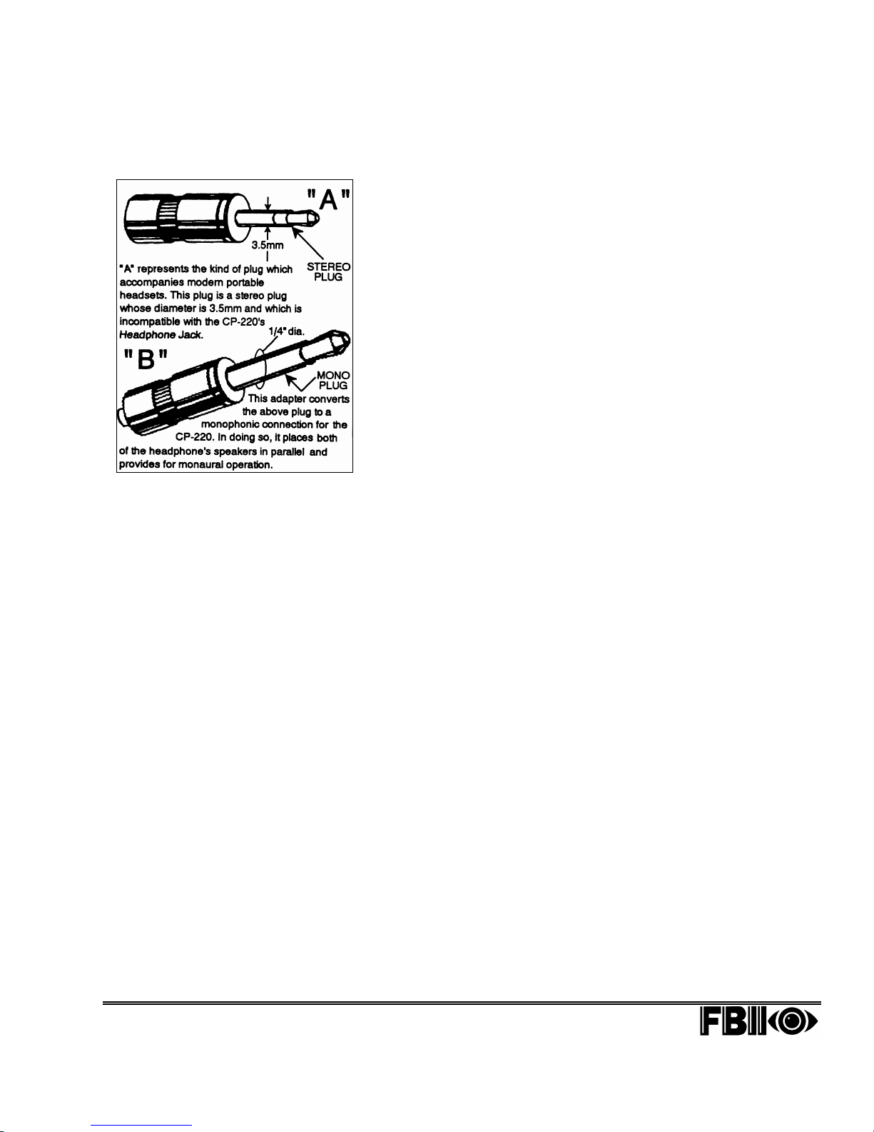
Headphone Jack
For private listening, the Headphone Jack will accept
standard ¼ inch monophonic plug to which an 8-ohm
monaural headset is connected. When used, the headset will
silence the loudspeaker.
If necessary, stereo headsets (like those used with
Walkman®-type products) that have 3.5mm-diameter stereo
mini-plugs (see "A" at the left) can be accommodated to
operate with the CP-220A by following the steps below:
1. For best performance with the CP-220A, the stereo
headphones you obtain should have an impedance as
close to 8 as possible.
2. Purchase an adapter that converts the headphone's
3.5mm stereo mini-plug to a ¼" monophonic plug (see "B"
at the left).
NOTE: An adapter manufactured by International
Components Corporation (Model 35-160) or its
equivalent will be suitable for this purpose. I
desired, call (800) 645-9154 or (516) 293-1500 for
list of ICC distributors.
Volume Control
The Volume Control adjusts the volume level of the speake
or, if used, the headset. It also affects the output leve
obtained from the "Listen-In Audio" terminals on the rear o
the receiver (see Figure 1-6).
LED Indicators
Eight LED (Light-Emitting Diode) indicators are provided to
represent each of the 8 possible Line Cards that the
CP-220A is capable of using. Each LED, when lit, indicates
that there is activity on the corresponding Line Card. Unde
typical conditions, it is normal for an LED to flash on and of
when processing data.
Page 1-10 Section 1: Getting Acquainted CP-220A Central Station Receiver
Hook-Up and Installation Manual
n
n
Page 17
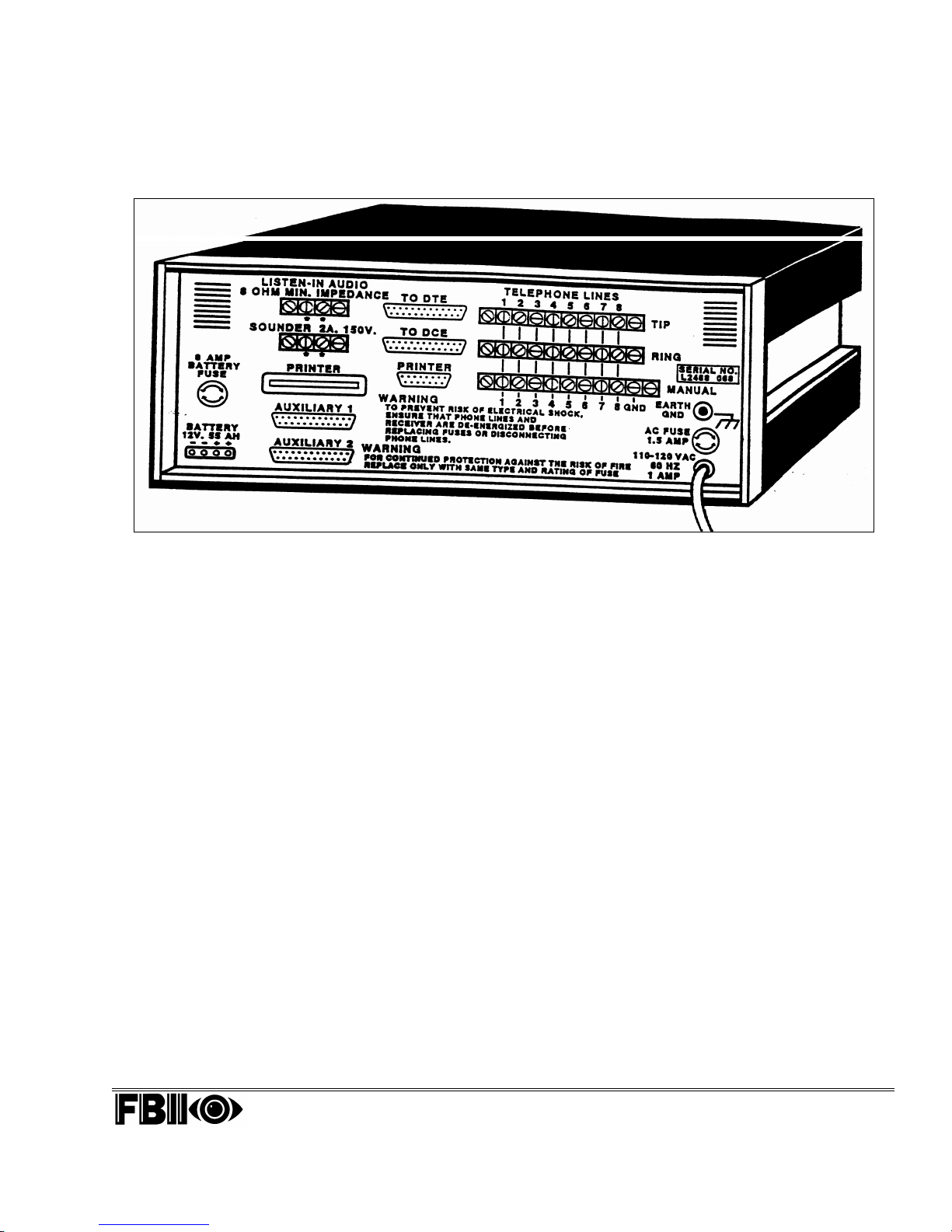
The Rear Panel
a
A
f
r
of the CP-220A
The CP-220A’s rear panel is equipped
with a variety of connectors for
attachment to devices in the “outside
world.” Among them: a Printer, used to
provide a “hard copy” of all events
passing through the receiver; and a
Computer, used to automate Central
Station operations.
CP-220A Central Station Receiver Section 1: Getting Acquainted Page 1-11
Hook-Up and Installation Manual
The rear panel of the CP-220A contains two fuses and
variety of connection points for several types of devices and
services, each of which will be discussed below.
FIGURE 1-6
• AC Power
• a Standby Battery
• an Earth Ground connector
• incoming Telephone Service
• connections to test the interaction between a Digital
Communicator and the Line Cards in the CP-220
without the need for telephone service
• a Printer for logging events
• a Computer for Central Station Automation
• a remote alerting Sounder
• a remote Listen-In Speaker or tape recorder
• a Modem for remote communication of the data received
by the CP-220A
The details of each of these devices and their connections are
discussed below.
AC Power
The AC Line Cord at the lower right of the rear panel is
plugged into a 120 Volt AC / 60 Hertz (Hz) source o
commercial power, which must not be switch-controlled.
Because the CP-220A has no ON/OFF switch, it will powe
up as soon as it's plugged in.
Page 18

What Makes a Good Ground?
Grounding provides a degree of
protection for any piece of electronic
equipment against lightning-induced
transients, which may cause
permanent or temporary general
malfunctions.
The ideal “ground” is considered to
be a
unified earth ground
8-foot copper-clad rod, located close
to the existing power and telephone
ground rods, is sunk several feet into
the earth. Appropriate hardware and
clamps are then used to electrically
connect each of these rods together.
Since this procedure is difficult in
most cases, an alternative earth
ground connection can be made to a
conductive metal cold water pipe
within the premises. Because such
pipes ultimately route their way into
the earth, the attachment to the pipe
of a suitable metal clamp and a
length of wire can make an effective
ground connection for the CP-220A.
When connecting the ground wire,
observe the limitations cited at the
right and make sure the connection
is secure. Also, verify that the pipe is
metallic throughout its entire run into
the earth, because much of today’s
plumbing is made from PVC (plastic)
compounds. Do not use a hot water
pipe for grounding because it will
likely attach to a heating apparatus
that may not, itself, be grounded.
It may be possible to use an existing
electrical ground on the premises if
one is close enough to the receiver.
Ideally, that ground can be obtained
at the metal panel where the
incoming electrical service originates.
Once again, use the same guidelines
cited for your wiring and be sure the
wiring attachment is secure. If in
doubt, you may wish to enlist the
help of a licensed electrician in
matters concerning grounding.
in which an
AC Fuse
Directly above the Line Cord is the unit's "master fuse." If
this fuse is either blown or removed, the CP-220A will be
unable to operate from AC power. After the cause of a blown
fuse is determined, replace it with an AGC-Type or
GLH-Type 1½-ampere fast-blow fuse. The approximate
dimensions of this fuse are 1¼" long x ¼" diameter. The AC
Fuse can be removed by pressing down on the cap and
turning it a quarter turn to the left. Replace fuses in the
opposite manner.
NOTE: The CP-220A will operate without its AC Fuse if a
suitable Standby Battery is properly connected and
the Battery Fuse is intact. The Standby Battery and
its fuse are discussed below.
Earth Ground
To protect the CP-220A from damage due to the effects of
lightning, a solid 14-gauge wire (or larger [numerically
lower] size) must be attached to this terminal and run to
where an acceptable electrical ground connection can be
made. Keep this wire as short as possible and do not run it
in conduit, coil it, bend it sharply, or run it alongside other
wiring. If you must bend it or change its direction, it should
have a radius of at least 8 inches at the point it is bent.
Additional grounding information is provided at the left.
Standby Battery
At the lower left corner of the rear panel is a white molex
connector used for the connection of a standby battery.
Standby batteries will, in the absence of AC Power or an
intact AC fuse, operate the CP-220A for up to 24 hours,
depending on the amount of activity logged by the Central
Station.
This battery, a 12-Volt, 55 Amp-Hour (AH) rechargeable gel
cell, is connected to the CP-220A via an FBI-furnished
No. 135 cable. The battery charging current is limited to a
maximum of 5 amperes. Refer to Figure 1-6 on previous
page.
NOTE: Using a Globe, 12-Volt DC, 55AH, UL-Listed gel cell
(or equivalent) will maintain the CP-220A's
operation for (typically) 24 hours in the event of an
AC power outage.
UL NOTE: When used for Central Station Service, a
minimum of 24 hours of backup power is required.
When used for Remote Station Service, a minimum
of 60 hours of backup power is required.
Page 1-12 Section 1: Getting Acquainted CP-220A Central Station Receiver
Hook-Up and Installation Manual
Page 19

Battery Fuse
Directly above the Standby Battery Connector is the unit's
Battery Fuse, which protects both the CP-220A and the
battery against the high currents that would occur if the
battery were connected with its polarity reversed. The
battery fuse is an AGC-Type or GLH-Type 8-ampere
fast-blow fuse, and like the AC Fuse, its approximate
dimensions are 1¼" long x ¼" diameter. As before, remove
such a fuse by pressing down on the cap and turning it a
quarter turn to the left. Replacement is done in the opposite
manner.
NOTE: The CP-220A will operate from a suitable Standby
Battery if the receiver is either deprived of AC
power or its AC Fuse is blown.
Listen-In Audio Connector
At the upper left of the rear panel, a set of two terminals is
provided (marked by two asterisks) for the connection of an
external device (e.g., a loudspeaker or a tape recorder) that
can be used to monitor or record the audible activities that
take place at the premises while a Listen-In account is
reporting.
Any device connected in this manner must present an
impedance to the CP-220A of no less than 8 ohms, and will
receive the same output provided to the front panel's
loudspeaker and headphone jack. The output at these
terminals is affected by the volume control on the front
panel but is not influenced by the connection of
headphones.
More information about Listen-In Accounts can be found in
Section 2.
NOTE: Connection of a tape recorder to the Listen-In Audio
Connector may require a special cable or the
modification of the cable supplied with the recorder.
Sounder
The two corresponding terminals (marked by two asterisks)
represent a set of normally-open dry contacts that close
whenever the receiver's internal sounder is activated. They
allow for the connection of a remote annunciating device,
either audible or visual, which can be used to alert
personnel in another area of the Central Station that the
receiver may require attention or operator intervention.
CP-220A Central Station Receiver Section 1: Getting Acquainted Page 1-13
Hook-Up and Installation Manual
Page 20
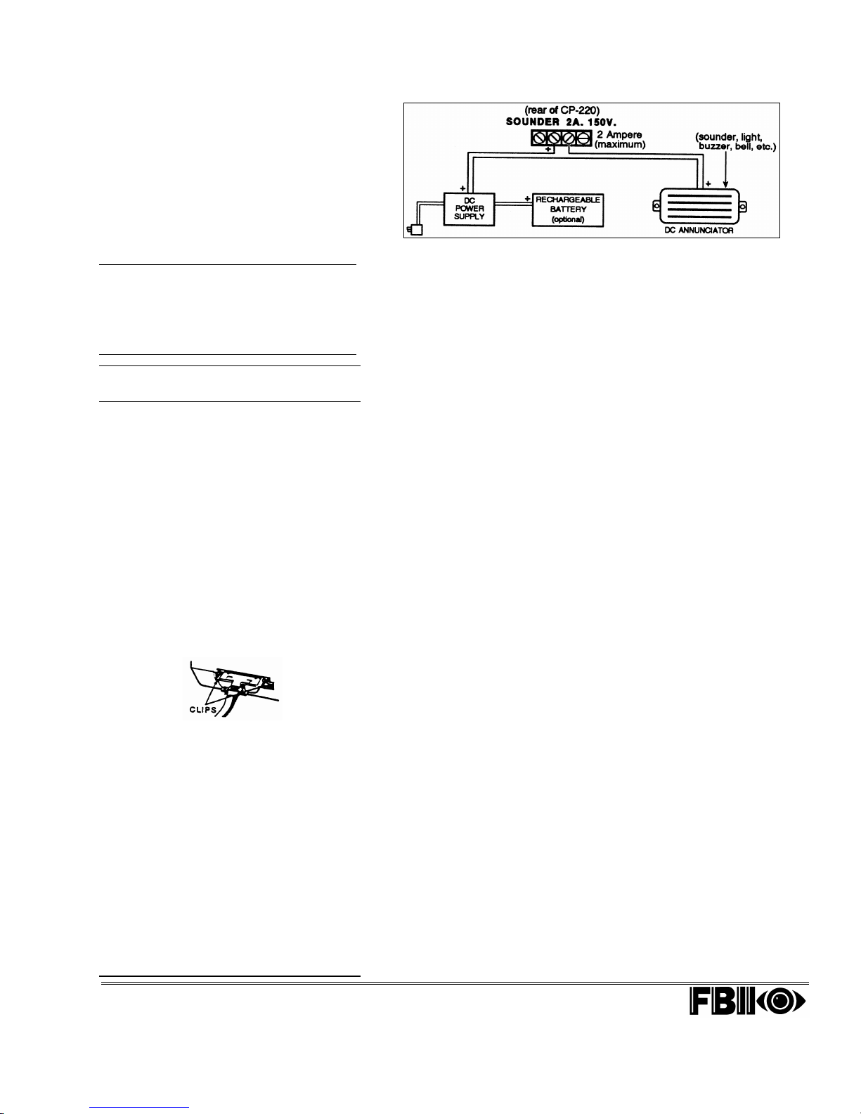
Remote annunciation – either audible, or
visual, or both – can be triggered by the
CP-220A whenever its own internal
sounder is activated. A typical application
of this process is shown at the right.
Important!
The cable numbers designated in this
printer port and the next two CP-220A
ports appear on the rear panel above
the port.
What Kind of Printer?
What Kind of Cable?
Even with an Automation System installed, a printer
that can log the events processed by the CP-220A
is highly desirable for several reasons:
• it prints a hard-copy reference of all CP-220A
activities as they occur
• resulting printouts can be used for diagnostic
purposes
• such printouts represent a legal record of the
receiver's operation and may be needed for this
purpose.
The best type of printer for event logging is a
common
(also known as a
connected to the receiver with a suitably long cable
(not to exceed 10 feet), equipped with a
connector at each end and secured by clips for that
purpose.
Virtually any such printer will be suitable, but for
Central Stations that must meet Underwriters
Laboratories requirements, only printers and cables
"listed" by UL may be used. If this is the case, FBI
can supply a custom-made cable (No. 132A) for this
purpose. Additionally, a list of several printers that
have been recognized by UL for use with the
CP-220A appears below. Because this list is
changeable and printers are continually being
added and withdrawn from the market, feel free to
contact FBI (at (800) 645-7492) to obtain a revised
listing:
• any Centronics-manufactured printer
• ADEMCO No. 6960-1 • Epson LX-80 or RX-80
• Okidata 82, 82A, 86P, 92P, 93P, and 182
Dot Matrix Printer
Centronics
equipped with a
) interface. It must be
Centronics
parallel
FIGURE 1-7
These terminals are typically wired to close a circuit
between a remote power source and the annunciating
device. Refer to Figure 1-7 for details.
Printer (No. 132A Cable)
This connector (or port) feeds data to a printer used to log
all events processed by the CP-220A. A cable of the
appropriate length is required to join the printer and the
receiver and must be equipped with Centronics-type
connectors at each end. See the box on page 1-14 for
additional information
Printer (No. 132 Cable)
A similar connection can be made between the printer and
the receiver by using this alternate printer port, although
it's less common and requires a nonstandard cable.
To DTE (No. 133 Cable)
This connector (designated here as DTE [Data Terminal
Equipment]) feeds the "raw" data processed by the CP-220A
directly to the serial communications (or RS-232) port of a
computer, which, when used in conjunction with the
appropriate Central Station Automation Software, can
expedite and simplify the job of monitoring alarms.
The cable plugged into this port is known as a serial cable; the
end of this cable at the CP-220A is a 25-pin "DB"-type (male)
connector; its other end will vary according to the type of serial
port provided by the computer, and may have either 9 or 25
pins. The FBI No. 133 is a UL-Listed custom-made cable that
provides the proper wiring and required connectors for this
purpose.
Information about interfacing the CP-220A with a Central
Station Automation System is further discussed in Section 2
(see pages 2-73 and 2-74).
To DCE
This connector (designated here as DCE [Data
Communications Equipment]) is used to feed the "raw" data
processed by the CP-220A directly to the communications
Page 1-14 Section 1: Getting Acquainted CP-220A Central Station Receiver
Hook-Up and Installation Manual
Page 21
The 8 pairs of TIP and RING terminals
marked 1 through 8 accept up to eight
telephone lines and correspond to the
eight available Line Card slots within
the CP-220A. Each incoming
telephone line consists of two wires
designated as the "TIP" and "RING,"
which reflect their polarity. The normal
non-ringing, "on-hook" voltage
produced by such pairs is typically
between 48 and 55 volts DC, with the
positive conductor designated as "TIP"
and the negative conductor
designated as "RING." This
nomenclature dates back to the time
when switchboard operators used
phone plugs with "tip" and "ring"
conductors to make manual telephone
connections between calling parties.
While such methods are no longer is
use, the "tip" and "ring" designations
have remained.
(or RS-232) port of a modem or to another computer.
When used with a modem, the CP-220A can send the data
it processes via the modem to a remote location (similarly
equipped with a modem), where it can be viewed, printed,
and/or stored.
NOTE: The use of a modem in this regard is beyond the
scope of this manual. Inquiries about such
applications should be made to FBI's Technical
Support Department by calling (800) 645-7492.
The cable used with such applications is also known as a
serial cable and connects the CP-220A's DCE port to the
corresponding port on the modem (or computer). The end of
this cable at the CP-220A is a 25-pin "DB"-type connector;
as with the DTE cable mentioned earlier, its other end will
vary according to the type of serial port provided by the
modem (or computer). Once again, contact FBI for help in
cabling either of these ports to the corresponding
equipment.
AUX. 1 / AUX. 2
The AUX. 1 and AUX. 2 ports are used in conjunction with
a REC-10 Line Card, which, when installed in the receiver,
enables the CP-220A to receive and process signals from
Derived Channel equipment in use in various locales
throughout the country. Derived Channel technology
provides telephone system supervision so that, along with
alarms and system troubles, telephone service outages due
to vandalism, accidents, or weather conditions can be
reported to the proper Central Station.
The REC-10 Line Card is designed to process such
information using Versus Technologies' Base 10 format.
Telephone Lines
The CP-220A has the capacity to handle simultaneous
incoming calls from up to 8 telephone lines. As stated on
page 1-5, this requires the use of up to eight Line Cards,
each of which corresponds to one of the eight telephone line
connections on the CP-220A's rear panel.
CP-220A Central Station Receiver Section 1: Getting Acquainted Page 1-15
Hook-Up and Installation Manual
FIGURE 1-8
Page 22

n
n
r
A
y
f
–
What Is
Programming?
Preparing for
Programming
Page 1-16 Section 1: Getting Acquainted CP-220A Central Station Receiver
Hook-Up and Installation Manual
Beneath the "TIP" and "RING" designations, there are 9 screw terminals i
a row marked "MANUAL." Those numbered 1 through 8 correspond to Line
Card Slots 1 through 8 and can be used in the testing of Digital
Communicators without the need for a telephone line. Any Line Cards inside
the CP-220A can also be tested via this method.
At this point, the CP-220A Digital Receiver is ready to be programmed. The
CP-220A has many programmable features, called parameters, which ca
enhance and customize its operation to best suit the requirements of you
Central Station. As of this printing, the CP-220A has 63 programmable
parameters, which include setting the following items:
• how messages appear on the display
• the date and time that appear on the display
• the operation of the internal sounder
• the words displayed in response to various events
• whether the standby battery is periodically tested
Each parameter can be selected and changed by using the keypad on the
face of the receiver. In manufacturing the CP-220A, FBI has
pre-programmed all of the parameters with values, called defaults, which
represent common choices of receiver operation. Because of these defaults,
little additional programming is often required, and the operation should
proceed quickly and easily.
ll of the parameter values, whether they have been specificall
programmed or remain as specified by the defaults, do not require any
electrical power to be maintained in the CP-220A's memory. The obvious
benefit is that, were it ever necessary to move the receiver, all sources o
power could be completely disconnected and no re-programming would be
required.
Programming the CP-220A will begin in Section 2, which follows. At that
time, you may wish to start programming right away and you can do so
simply by plugging the CP-220A into a source of AC power. However, the
receiver will soon "complain" that the connections it expects to see from the
"outside world" are missing, and you'll be unable to begin programming until
you address this problem.
Page 23
2
r
r
S
Programming
With No External
Connections
Under such conditions, the receiver will quickly call your attention to the
following faults:
• it has no telephone service
• it finds no printer
• it has logged a battery failure (due to no standby battery)
Each fault will have to be acknowledged before any programming can be
performed. Alternatively, you can make all the required connections first,
and then you won't be disturbed by these messages. The table on the
following page summarizes the advantages and disadvantages of each
approach, after which they'll be covered individually.
If you choose to enter programming without wiring the receiver's external
connections, proceed directly to Section 2: Programming the CP-
20A
Receiver, which follows.
ADVANTAGE S DISADVANTAGES
PROGRAMMING WITHOUT
MAKING EXTERNAL
CONNECTIONS
PROGRAMMING AFTER
MAKING EXTERNAL
CONNECTIONS
Programming
After External
Connections
Have Been Made
• programming can be entered
without concern for wiring
phone lines or connecting a
battery or printer
• there will be no failure
messages and programming
can begin immediately
• all connections will be
automatically checked to
provide verification of correct
operation
• fault messages will be
displayed which must be
acknowledged before
programming can begin
• time consuming
However, if you wish to make the required connections, observe the
following by connecting:
• the proper TIP and RING telephone line connection to each pai
of terminals on the rear of the CP-220A for which a corresponding Line
Card is installed. As equipped from the factory, current CP-220As come
with two REC-11 Line Cards: one in Slot 1 and the other in Slot 8. It is
to these Telephone Line Terminals (1 and 8) where incoming telephone
service must be wired.
• a "parallel" printer and cable, as specified on page 1-14. Before
programming can begin, the printer must be powered on, have pape
loaded, and be "on-line"; if necessary, refer to the printer's instruction
manual for information relating to these conditions.
• a standby battery, connected as indicated in Figure 1-6 and as
described on page 1-12. Be very careful in handling and connecting the
battery and be sure to observe polarity when using the No. 135 cable.
When all these connections have been made, you may proceed to
ection 2:
Programming the CP-220A Receiver.
CP-220A Central Station Receiver Section 1: Getting Acquainted Page 1-17
Hook-Up and Installation Manual
Page 24

Section 2
n
P
t
y
Programming the CP-220A Receiver
Introduction
Section 2 will take you through the "ins" and "outs" of programming your
CP-220A Receiver and will explain each of the 63 parameters used in
configuring the product. As stated in Section 1, each of these parameters has
been factory pre-programmed with defaults that reflect the common usages
and applications of the Receiver. In many cases, only a few of these
parameters may have to be re-programmed to satisfy the needs of the
Central Station.
All programming is done from the keyboard on the CP-220A's front panel.
Because the CP-220A's electronic memory is "non-volatile" – that is, it
retains data without the need for external power – all sources of power ca
be removed from the Receiver without losing the current configuration.
The 63 parameters span a range from 00 through 62. It is possible to
program each one in turn, beginning with 00 and ending with 62, but the
approach taken in Section 2 will be to group all the related parameters into
these three categories whose numbers are not always consecutive:
Preparation
for
Programming:
No External
Connections
Made
• Category A: Receiver Operation
• Category B: Printer Operation
• Category C: Computer (Automation System) Operation
Because not all Central Stations have a printer or an Automation System
connected to their CP-220A at this time, it may not be necessary to program
the parameters used for these devices until they're incorporated with the
Receiver.
If you choose to enter programming without making the external
connections discussed on page 1-17, perform the preliminary actions in the
steps detailed on the next page.
If you have already made these connections, proceed to
Programming: External Connections Have Been Made, on page 2-4.
• Insert the CP-220A's AC Line Cord into an unswitched electrical outle
supplying 120 Volts AC at 60 Hertz.
• During the next 25 seconds (approximately) while the CP-220A performs
some self-checks, its internal sounder will annunciate and several rela
activations may be heard. The MANUAL/PREVIOUS LED will illuminate,
and the NEXT LED will light soon after.
CP-220A Central Station Receiver Section 2: Programming the CP-220A Page 2-1
Hook-Up and Installation Manual
reparation for
Page 25

d
r
y
r
r
r
g
r
h
• At this point, check that your CP-220A's display appears like this:
SYSTEM RESET VER 3.91 01/01/00 00:00:25
• If the Receiver was previously in operation, its Date and Time and any
data or conditions that may have been reported earlier will be cleared.
However, as already stated, configuration data stored as programme
parameters will remain intact.
• VER. 3.91 refers to the latest version of the software being used by the
CP-220A as of this writing. The software routines responsible for its
operation have been electronically encoded into an integrated circuit (o
"chip") mounted within the Receiver. Because such software is continuall
being improved upon and updated, each time the system is powered on o
reset, the software's version (i.e., revision) number will always appear fo
reference purposes.
• The right side of the display indicates the Date, and the Time in a 24-hou
military format (HH:MM:SS). Whenever the CP-220A is reset through the
power-on process, the Date will revert to 01/01/00 and the Time to
00:00:00. The time shown in the figure above reflects the approximate
number of seconds that have elapsed since the Receiver has been powered
on before its Version Number appears.
"Error" Messages
When the NEXT LED is lit at this time, it indicates that the CP-220A has at
least one message to report. As stated in Section 1, this is an expected
response due to the Receiver's sensing the lack of several external
connections deemed necessary for its operation. Such messages are used to
report this condition, and it will not be possible to enter the Programmin
Mode unless each of these "error" messages has been acknowledged. Until
then, the Receiver will produce a short beep every 30 seconds, calling you
attention this condition.
In order to enter the Programming Mode, these "error" messages must be
displayed – which serves to acknowledge them. To do so, with the NEXT
LED lit, perform each of the following steps to clear all "error" messages. In
the process, some "normal" messages will appear. The beeps will continue to
sound periodically until all outstanding messages have been acknowledged.
The messages listed below are typical but may not be identical to that whic
will be displayed by your CP-220A at this time:
Page 2-2 Section 2: Programming the CP-220A CP-220A Central Station Receiver
Hook-Up and Installation Manual
Page 26
r
f
1. Press the NEXT key. The NEXT LED will go out and a moment late
this message will appear:
LINE CARD 1 OPERATIVE 01/01/00 HH:MM:SS
after which the NEXT LED re-illuminates.
NOTE: The above message assumes that the CP-220A is equipped with two
Line Cards. If there are additional Line Cards, this message will
not immediately address Line Card 8.
2. Press the NEXT key again. As before, the NEXT LED will go out, and
shortly, this message will appear:
LINE CARD 8 OPERATIVE 01/01/00 HH:MM:SS
One again, the NEXT LED will re-light.
3. Press the NEXT key again; the NEXT LED goes out and this message
subsequently appears:
LINE CARD 8 OPERATIVE BATT TEST FAIL
4. Repeat this procedure, each time pressing the NEXT key when the
NEXT LED illuminates and waiting for a new message to display. The
NEXT LED, when lit, serves as an indicator that another message is
waiting to be acknowledged. On the following page are illustrations o
the expected messages from this point on (with just two Line Cards
installed).
CP-220A Central Station Receiver Section 2: Programming the CP-220A Page 2-3
Hook-Up and Installation Manual
Page 27

t
g
y
t
y
Preparation for
Programming:
External
Connections
Have Been Made
LINE CARD 8 OPERATIVE PRINTER FAIL
LINE CARD 8 OPERATIVE LINE FAULT 1
LINE CARD 8 OPERATIVE LINE FAULT 8
NOTE: LINE FAULT messages like those illustrated above result when the
CP-220A checks for active telephone service at each Line Card bu
fails to find it.
5. Once the NEXT LED remains off, there are no more messages to
acknowledge. At this point it will be possible to enter the Programmin
Mode.
NOTE: Even though the previous faults are now acknowledged, the
remain uncorrected and will be annunciated again every 15
minutes (approximately) until they are remedied. When in the
Programming Mode, however, fault annunciation is suspended and
will not re-occur until the Programming Mode has been exited. A
that time, uncorrected faults will continue to be annunciated as
described above.
Proceed to Entering and Using the Programming Mode on page 2-5.
If you have already made the battery, printer, and telephone line connections
to your CP-220A, you are ready to enter the Programming Mode. First,
perform the following preliminary actions:
1. Insert the CP-220A's AC Line Cord into an unswitched electrical outlet
supplying 120 Volts AC at 60 Hertz.
During the next 25 seconds (approximately) while the CP-220A performs
some self-checks, its internal sounder will annunciate and several rela
activations may be heard. The MANUAL/PREVIOUS LED will
illuminate, and the NEXT LED will light soon after.
2. At this point, check that your CP-220A's display appears like this:
SYSTEM RESET VER 3.91 01/01/00 00:00:25
Page 2-4 Section 2: Programming the CP-220A CP-220A Central Station Receiver
Hook-Up and Installation Manual
Page 28

n
V
r
r
f
f
r
y
g
y
Entering and
Using the
Programming
Mode
If the Receiver was previously in operation, its Date and Time and any data
or conditions that may have been reported earlier will be cleared. However,
as already stated, the data stored as programmed parameters will remai
intact.
ER. 3.91 refers to the version of the software currently being used by the
CP-220A as of this writing. The software routines responsible for its
operation have been electronically encoded into an integrated circuit (o
"chip") mounted within the Receiver. Because such software is continually
being improved upon and updated, each time the system is powered on, the
software's version (i.e., revision) number will always appear for reference
purposes.
The right side of the display indicates the Date and the Time in a 24-hou
military format (HH:MM:SS). Whenever the CP-220A is reset through the
power-on process, the Date will revert to 01/01/00 and the Time to 00:00:00.
The time shown in the figure above reflects the approximate number o
seconds that have elapsed since the Receiver has been powered on.
Each CP-220A Receiver has been given a different 4-digit Access Code that
must be used to gain entry to the Programming Mode. The Access Code
should be available only to those individuals who have the responsibility o
maintaining and updating the Receiver. Additional information about the
Access Code can be found on page 1-8.
To enter and use the Programming Mode, read the steps below, which offe
general information for all programming parameters. Don't perform an
actions just yet; afterward, you will be able to apply it to Programmin
Category A.
1. With the NEXT LED off, enter the 4-digit Access Code described above.
The CP-220A will display:
This display always appears when first entering the Programming Mode.
The current Date and Time will be displayed for Receivers that have alread
been programmed with this information.
CP-220A Central Station Receiver Section 2: Programming the CP-220A Page 2-5
Hook-Up and Installation Manual
PARAMETER NUMBER 00/01/00 HH:MM:SS
Page 29
g
y
n
A
r
y
r
n
n
2. The first [0] after [PARAMETER NUMBER] will be flashing. A flashin
digit serves as a "cursor" and marks the spot where any keyboard entr
will be placed. From this display, any parameter can be reached and
programmed. To choose the desired parameter, simply enter the twodigit number identifying it. To go to PARAMETER 03, for example,
press 0, then 3.
Note that in any parameter screen, the current Date and Time will remai
active, and always appears at the right.
3.
dvancing from one parameter to the next is easy. Once a particula
parameter has been programmed, advance to the next parameter b
using one of the following methods:
• Press the
key to advance to the next sequential parameter.
• Press the
key to advance to the previous parameter.
NOTE: When the arrow keys are used, only the name of the next parameter
is displayed, not its number.
• Press the N key at any time to reveal the number of the last (i.e.,
current) parameter to be programmed, from which it can be changed.
The display below results when the N key is pressed afte
programming PARAMETER 03.
PARAMETER NUMBER 03/01/00 HH:MM:SS
• Enter the two digits of the next parameter to be programmed; once
done, the parameter's name and the current value it has stored will be
displayed.
• Press the
key to move the flashing digit position one character to
the right; similarly, use the key to move it one character to the left.
These keys are useful when it's easier to change just one character i
a series, rather than entering all its digits.
4. To change the value of any parameter, press the NEXT key successively
to move forward through the selections, or the MANUAL/PREVIOUS
key to move backward through them until desired value has bee
reached.
Page 2-6 Section 2: Programming the CP-220A CP-220A Central Station Receiver
Hook-Up and Installation Manual
Page 30

g
g
f
y
g
Parameters in Category A:
Receiver Operation
PARAMETER 03: Receiver
Number
PARAMETER 04: Sounder
PARAMETER 05: Group Number
PARAMETER 07: Handshake
PARAMETER 08: Handshake
Delay
PARAMETER 26: Set Time
PARAMETER 28: Slot English
Language
PARAMETER 29: Copy Slot
PARAMETER 30: Slot English
On/Off
PARAMETER 27: Cannel English
PARAMETER 31: Operator
Log On
PARAMETER 32: Listen-In Time
PARAMETER 33: Listen-In
Accounts
PARAMETER 36: Battery Test
PARAMETER 37: Manual Turnoff
of Sounder
PARAMETER 40: Automatic
Mode Enable
PARAMETER 42: Line Fault
Detector
PARAMETER 44: 3x1 with Parity
PARAMETER 47: FBI English
PARAMETER 55: FBI Superfast /
LAR300
PARAMETER 56: Handshake
Duration
PARAMETER 57: Auto Mode
Sounder
(On/Off)
PARAMETER 58: Date Format
PARAMETER 59: 4x2 with Parity
PARAMETER 60: 4x1 with Parity
PARAMETER 61: Extended
BFSK Alarms
PARAMETER 62: Programmable
Handshakes
5. To leave the Programming Mode at any time, press the Esc
key. Doing so will return the CP-220A to its normal operating
mode.
6. Messages reported while the CP-220A is in its Programmin
Mode will be processed and stored but will not interrupt the
programming operation unless 30 seconds go by without any
programming activity from the CP-220A's keypad.
At that time, the CP-220A will automatically exit the programmin
mode and, if the unit was set for AUTOMATIC operation, pass the
message on to the printer (and automation system, if available); or, i
the unit was set for MANUAL operation, display it (and pass it on).
Therefore, if the receiver is "on line" and a parameter change must be
made, it's best to make the change quickly.
Once you begin to program the Receiver, each of these steps will
become very clear.
Category A: Receiver Operation
This material will cover the programming of the parameters found in
Category A, Receiver Operation. As stated on page 2-1, three distinct
categories have been selected into which each of the CP-220A's
programming parameters have been placed. Programming the
CP-220A's parameters according to category, rather than by numerical
sequence, is thought to be a more logical approach and is generall
easier.
A complete guide to programming all the parameters in Category A
(see column at left) will be covered here. In the discussion of each
parameter, you will be provided with:
The programming of Category A parameters begins with the followin
display, which appears upon entering the 4-digit Access Code.
• background information
• programming options
• an explanation of the default
• the next logical parameter in Category A
CP-220A Central Station Receiver Section 2: Programming the CP-220A Page 2-7
Hook-Up and Installation Manual
PARAMETER NUMBER 00 MM/DD/YY HH:MM:SS
Page 31

PARAMETER 03:
r
n
r
t
From the previous display, press 0 and 3 . The following screen appears:
Receiver Number
REMEMBER!
To leave the
Programming Mode
at any time, press
the Esc key. Doing
so will return the
CP-220A to its
normal operating
mode. Programming
changes will be
stored automatically.
Page 2-8 Section 2: Programming the CP-220A CP-220A Central Station Receiver
Hook-Up and Installation Manual
Background:
A Receiver Number must be assigned to each CP-220A. The Receiver Numbe
allows Central Stations to identify, track, and route incoming data in the
event that more than one Receiver is being used. In Central Stations
employing several Digital Receivers and a computerized Automatio
System, the Receiver Number becomes essential to this process. In eithe
case, the Receiver Number becomes part of the alarm (or trouble) report.
Programming Procedures:
36 different Receiver Numbers (or designations) are available for each
CP-220A. Any number between 0 (zero) and 9 and any letter between A and
Z may be entered as required.
Press the NEXT key or the MANUAL/PREVIOUS key until the desired
choice is reached.
Default:
The factory has pre-programmed each CP-220A as Receiver 0 (zero). Unless
there are other considerations like those already mentioned, this designation
should be satisfactory at this time.
Advancing to Next Parameter:
After programming PARAMETER 03, press the N key to advance to
PARAMETER 04 – the next parameter in Category A.
The CP-220A displays the parameter just programmed ([PARAMETER
NUMBER 03]) with its first digit flashing, indicating its request for the nex
parameter number.
You can reach PARAMETER 04 in one of several ways. Press either:
NOTE: When the is used, the name of the next parameter appears
RECEIVER NUMBER 0 MM/DD/YY HH:MM:SS
• 0 then 4, or
• the key and 4 , or
• the key
immediately – not its number.
Page 32

PARAMETER 04:
n
t
A
r
r
y
f
t
Sounder
Background:
The CP-220A's Internal Sounder is used to call the operator's attention to a
incoming data transmission or to an error message or condition tha
requires attention and will annunciate for several seconds. Central Stations
using Automation Systems may prefer to keep the sounder off because the
REMEMBER!
To leave the
Programming Mode
at any time, press
the Esc key. Doing
so will return the
CP-220A to its
normal operating
mode. Programming
changes will be
stored automatically.
and error messages are received. However, turning the sounder off unde
these circumstances may prevent operator notification of every erro
condition involving the CP-220A. If you choose to turn the sounder off, be
sure that all error messages unique to the CP-220A will be annunciated b
the Automation System.
Programming Procedures:
[SOUNDER ON] will be displayed after entering PARAMETER 04. The
Sounder may be programmed to be ON or OFF, as desired, by pressing the
NEXT or the MANUAL/PREVIOUS key until the desired choice is reached.
Default:
The factory has pre-programmed the sounder to be ON. If kept on, the
sounder will operate regardless of whether the Receiver is in its
AUTOMATIC or MANUAL mode (see page 2-103), and will be subject to the
settings used in PARAMETER 37 (for the MANUAL Mode) and
PARAMETER 57 (for the AUTOMATIC Mode). If kept OFF in
PARAMETER 04, it cannot be turned on by any settings made in either o
the other parameters.
Advancing to Next Parameter:
After programming PARAMETER 04, press the key to advance to
PARAMETER 05 – the next parameter in Category A.
The CP-220A displays the parameter just programmed ([PARAMETER
NUMBER 04]) with its first digit flashing, indicating its request for the nex
parameter number.
You can reach PARAMETER 05 in one of several ways. Press either:
SOUNDER ON MM/DD/YY HH:MM:SS
utomation System itself often provides an "alert" when data transmissions
• 0 then 5 , or
NOTE: When the is used, the name of the next parameter appears
CP-220A Central Station Receiver Section 2: Programming the CP-220A Page 2-9
Hook-Up and Installation Manual
• the key and 5 , or
• the key
immediately – not its number.
Page 33

PARAMETER 05:
r
f
R
r
g
n
y
A
Group Number
SLOT 1 IS IN GROUP 1 MM/DD/YY HH:MM:SS
Background:
As previously stated, the CP-220A has eight internal slots for use with
either REC-1 or REC-11 FBI Line Cards. Each slot, in turn, has
corresponding phone line terminals at the rear of the Receiver. As a result,
your Central Station can connect up to eight separate phone lines – one pe
slot and each with a different phone number – to receive incoming reports o
alarms and troubles from Subscriber Accounts.
Alternatively, another type of phone system, known as a Rotary or
system, may be used. In this type of arrangement, several or many lines are
accessed via the same telephone number, much like calls to a company's
switchboard. This kind of phone system automatically routes an incomin
call to the first available open (not busy) line. Programming PARAMETER
05 depends on the type of phone system in use.
Generally, when separate phone numbers are wired to a Central Statio
Receiver, each Line Card slot corresponding to the connection is assigned a
unique Group Number. This Group Number, like the Receiver Number (see
These two nearly
identical reports come
from two different
Subscriber Accounts. In
busy Central Stations
monitoring thousands of
alarm systems, the
limitations on the number
of subscribers that each
REC-11 Line Card can
process (over 65,000 with
hexadecimal in use) may
require that the same
Account Number be used
several times by different
subscribers. If such
“duplicate” subscriber
accounts were
programmed to call in on
different phone lines, the
Group Number, which is
part of the alarm report, is
used to distinguish them
from one another.
Page 2-10 Section 2: Programming the CP-220A CP-220A Central Station Receiver
Hook-Up and Installation Manual
PARAMETER 03), becomes part of the alarm (or trouble) report. B
assigning Group Numbers to Line Card slots in this manner, the same
ccount Numbers may be used more than once for a given Receiver. Refer to
Figure 2-1.
ollove
Page 34

When the Rotary or Rollover type of phone system is used, every Subscribe
r
A
y
f
S
s
g
t
y
R
r
ccount calls the same phone number and awaits routing to the next "open"
line before generating its alarm or trouble transmission. Since it is
unpredictable as to which of the phone lines will be available at any given
time, there is no way of knowing which of the CP-220A's Line Cards will be
processing the data. In situations like this, each Receiver slot must be
assigned the same Group Number to avoid confusion.
For this reason, the maximum number of accounts that can be processed b
Receivers connected to a Rotary or Rollover phone system cannot exceed the
maximum number of accounts available to any single Line Card (up to
65,000 with hexadecimal in use). Although this is a limitation in the use o
Rollover systems, a greater number of individual Line Cards found in a
Receiver enables better call throughput.
Programming Procedures:
For Receivers using separate phone lines, the numbering of the CP-220A's
slots should be left as pre-programmed by the factory. In other words,
1 through 8 will correspond to Groups 1 through 8 by default.
For use with Rotary or Rollover systems, program each slot with the
number.
As stated, [SLOT 1 IS IN GROUP 1] will be displayed after enterin
PARAMETER 05. The number [1] after [SLOT] will be flashing.
If it is necessary to change Slot 1's Group Number from Group 1 to
something else, take the following steps:
1. Depress the
key once. The [1] after [GROUP] will begin to flash; the
Group Number of Slot 1 may be altered at this time.
2. Press the NEXT key or the MANUAL/PREVIOUS key until the desired
choice is reached. After doing so, Slot 1 will be assigned to the chosen
Group.
3. Press the
key so that the [1] after [GROUP] flashes again.
4. To assign another Slot to a new Group, press the number key of the slo
desired (e.g., 2 ); the chosen Slot Number and its currently assigned
Group Number will be displayed.
5. Repeat the above steps for each Slot Number to which you desire to
assign a new Group. Slots 1 through 8 can be programmed to an
Group 1 through 8, as desired.
Default:
Slots 1 through 8 have been assigned to Groups 1 through 8, respectively,
through the factory defaults. Change this only if a Rotary or
telephone system is in use for the CP-220A.
CP-220A Central Station Receiver Section 2: Programming the CP-220A Page 2-11
Hook-Up and Installation Manual
lots
ame
ollove
Page 35

t
n
g
P
r
S
Advancing to Next Parameter:
After programming PARAMETER 05, press the N key to advance to
REMEMBER!
To leave the
Programming Mode
at any time, press
the Esc key. Doing
PARAMETER 06 – the next parameter in Category A.
The CP-220A displays the parameter just programmed ([PARAMETER
NUMBER 05]) with its first digit flashing, indicating its request for the nex
parameter number.
You can reach PARAMETER 06 in one of several ways. Press either:
so will return the
CP-220A to its
normal operating
mode. Programming
changes will be
stored automatically.
NOTE: When the is used, the name of the next parameter appears
PARAMETER 06:
• 0 then 6 , or
• the key and 6 , or
• the key
immediately – not its number.
Ring Signal
SLOT 1 NEEDS 1 RINGS MM/DD/YY HH:MM:SS
Background:
The Line Cards in each of the eight slots may be programmed to "pick up" o
an incoming call immediately (i.e., after 1 ring) or after an extended time
(i.e., up to 8 rings).
On occasion, random "noise" on a phone line may affect the correspondin
Line Card, which may interpret the noise as a Ring – causing it to pick up
the line in error. In consideration of this possibility, it may be desirable to
program additional Ring Signals so that sporadic noise will not cause an
immediate pickup. Before doing so, bear in mind that the use of additional
Ring Signals will slightly delay the processing of legitimate alarm reports.
Programming Procedures:
As stated, each Slot Number may be programmed to pick up the
corresponding line after waiting between 1 and 8 rings.
[SLOT 1 NEEDS 1 RINGS] will be displayed after entering
06. The number [1] after [SLOT] will be flashing.
If it is necessary to change the number of rings that Slot 1 will listen fo
before picking up a call, take the following steps:
1. Depress the
number of rings required by Slot 1 may be altered at this time.
2. Press the key representing the number of rings appropriate for
(i.e., press 2 for two rings). The chosen number of rings will be assigned
to Slot 1.
3. Press the
Page 2-12 Section 2: Programming the CP-220A CP-220A Central Station Receiver
Hook-Up and Installation Manual
key once. The [1] before [RINGS] will begin to flash. The
key so that the [1] after [SLOT] flashes again.
ARAMETER
lot 1
Page 36

y
t
a
n
f
r
4. To change the number of rings assigned to a different slot, press the ke
5. Repeat the above steps for each Slot Number for which a change in the
Default:
The factory has pre-programmed each slot to pick up the line after the firs
ring.
Advancing to Next Parameter:
REMEMBER!
To leave the
Programming Mode
at any time, press
the Esc key. Doing
so will return the
CP-220A to its
normal operating
mode. Programming
changes will be
stored automatically.
After programming PARAMETER 06, press the N key to advance to
PARAMETER 07 – the next parameter in Category A.
The CP-220A displays the parameter just programmed
([PARAMETER NUMBER 06]) with its first digit flashing, indicating its
request for the next parameter number.
You can reach PARAMETER 07 in one of several ways. Press either:
NOTE: When the is used, the name of the next parameter appears
PARAMETER
07:
Handshake
SLOT 1 HI/LO IS 0 MM/DD/YY HH:MM:SS
Background:
Whenever the Digital Communicator at a subscriber's premises is activated
and calls the Central Station, it waits for confirmation that the Digital
Receiver is ready to accept the report. This confirmation, known as
handshake signal, is a tone sent from the Receiver back to the
Communicator, indicating that the Receiver is "on-line" and ready to process
data from the account (see Figure 1-1 on page 1-2).
Because there are many kinds of Digital Communicators and communicatio
standards in use today, there are also several different types of handshake
signals that Digital Receivers like the CP-220A must be capable o
generating. Often, the type of handshake tone sent back to the
communicator reflects the kind of transmission format the Digital Receive
is able to process, and serves to prompt the communicator to transmit its
data in that format.
CP-220A Central Station Receiver Section 2: Programming the CP-220A Page 2-13
Hook-Up and Installation Manual
corresponding to the desired slot (e.g., 6 ); the chosen Slot Number and
the rings currently assigned to it will be displayed.
number of rings is required. Slots 1 through 8 can be programmed to
answer after between 1 and 8 rings.
• 0 then 7 , or
• the key and 7 , or
• the key
immediately – not its number.
Page 37

A
t
r
There are three kinds of handshake signals that can be produced by the
CP-220A:
• The 2300 Hz (Hertz, or cycles per second) handshake signal is a "high-
frequency" tone that is generally interpreted by Digital Communicators as
an "invitation" to communicate in a High Speed format.
• Similarly, the 1400 Hz handshake signal is a "low-frequency" tone that is
generally sent by the Receiver if there is no response to its initial 2300 Hz
handshake signal. The 1400 Hz tone invites the Digital Dialer to
communicate in a Low Speed format.
• The Hi/Lo handshake signal is really two distinct tones that use both the
2300 Hz and 1400 Hz frequencies, and is used with the
Speed (Superfast), ADEMCO Express, and ADEMCO Point I.D. (i.e.,
Contact I.D.) communication formats. In the event that there are
ADEMCO dialers reporting in these formats, it will be necessary for the
CP-220A to transmit at least one Hi/Lo handshake signal.
NOTE: See Appendix B for additional information.
Digital Communicators, after receiving a handshake signal from the Central
Station, will respond only if the handshake corresponds to the data forma
the Dialer has been programmed to send. If the handshake is not responded
to, the CP-220A will produce an alternate handshake that the Dialer should
find compatible.
Programming Options:
The programming for PARAMETER 07 specifies whether or not each of the
CP-220A's Line Cards will send the Hi/Lo handshake signal, and if so, how
many times (up to 2).
[SLOT 1 HI/LO IS 1] will be displayed after entering PARAMETER 07. The
number [1] after [SLOT] will be flashing. Each of the 8 slots can be
programmed to deliver between zero and two Hi/Lo handshakes if that's
desired or necessary. Note that only one Hi/Lo handshake is required fo
Communicators transmitting in the ADEMCO Superfast or Point I.D.
format, although two such handshakes can be programmed to increase the
chances for a successful connection when noisy phone lines are encountered.
Page 2-14 Section 2: Programming the CP-220A CP-220A Central Station Receiver
Hook-Up and Installation Manual
DEMCO High
Page 38

r
a
f
y
S
IMPORTANT!
Briefly stated, the
programming for
PARAMETER 07
determines how many Hi/Lo
handshakes will be produced
by each of the CP-220A’s
slots. Any selections made in
PARAMETER 07 also have
a bearing on the order in
which the remaining
handshakes are sent, which
is illustrated in the table at
right.
When greater flexibility is
required – in terms of the
sequence in which a Line
Card produces its
handshakes – you must also
program PARAMETER 62
(on page 2-59), whose
settings, when used in
conjunction with the number
of Hi/Lo handshakes
specified in PARAMETER
07, will allow for complete
customization.
Note that PARAMETER 62
is available only with
Versions 3.91 (and above) of
the CP-220A’s software (see
page 2-5), and will apply only
to REC-11 Line Cards
whose NLC (New Line Card)
software is Version 3.0 (or
above).
Examples of coordinating
programming options
between PARAMETER 07
and 62 can be found on
page 2-60.
The following table lists the sequence of handshake signals generated fo
each of the three choices (0, 1, and 2) available for this parameter:
NUMBER OF HI/LO SEQUENCE OF HANDSHAKE
HANDSHAKE SIGNALS SIGNALS GENERATED
PROGRAMMED
0 2300 Hz 1400 Hz
1 Hi/Lo 1400 Hz 2300 Hz
2 Hi/Lo Hi/Lo 1400 Hz 230 Hz
If you're not sure if the Communicators reporting to any Line Card require
the Hi/Lo handshake to produce data in the Superfast or Point I.D. format,
accept the default (1) for PARAMETER 07 (see page 2-16). This will cause
single transmission of the Hi/Lo handshake, which, if ignored, produces
first the Low Frequency handshake (1400 Hz); then, if no response is
received, it produces the High Frequency (2300 Hz) handshake, to
ultimately effect communication with the subscriber.
However, if it's known that the all the accounts reporting to a single Line
Card do not require the Hi/Lo handshake, it's best, in the interests o
transmission time, to program the parameter with "0" (zero) so that no Hi/Lo
handshakes are generated by the Line Card.
Programming Procedures:
If it is necessary to change the number of Hi/Lo handshakes that Slot 1 will
generate after picking up a call:
1. Depress the
will begin to flash. The number of such handshake signals produced b
Slot 1 may be altered at this time.
2. Press the key representing the number of "Hi/Los" appropriate for
(i.e., press for two such handshakes). The chosen number of "Hi/Los"
will be assigned to Slot 1.
3. Press the
4. To change the number of "Hi/Los" assigned to a different slot, press the
key corresponding to the desired slot (e.g., 8 ); the chosen Slot Number
and the number of "Hi/Los" currently assigned to it will be displayed.
5. Repeat the above steps for each Slot Number for which a change in the
number of "Hi/Los" is required. Slots 1 through 8 can be programmed to
produce up to 2 Hi/Lo handshake signals; all other values will be
ignored.
Default:
The factory has pre-programmed each slot to generate one Hi/Lo
handshake.
CP-220A Central Station Receiver Section 2: Programming the CP-220A Page 2-15
Hook-Up and Installation Manual
key once. The [1] indicating the quantity of [HI/LOs]
lot 1
key so that the [1] after [SLOT] flashes again.
Page 39

t
y
S
Advancing to Next Parameter:
After programming PARAMETER 07, press the N key to advance to
REMEMBER!
To leave the
Programming Mode
at any time, press
the Esc key. Doing
PARAMETER 08 – the next parameter in Category A.
The CP-220A displays the parameter just programmed ([PARAMETER
NUMBER 07]) with its first digit flashing, indicating its request for the nex
parameter number.
You can reach PARAMETER 08 in one of several ways. Press either:
so will return the
CP-220A to its
normal operating
mode. Programming
changes will be
stored automatically.
NOTE: When the is used, the name of the next parameter appears
PARAMETER 08:
• 0 then 8 , or
• the key and 8 , or
• the key
immediately – not its number.
Handshake Delay
SLOT 1 DELAY IS 1 SEC MM/DD/YY HH:MM:SS
Background:
After waiting the pre-programmed number of Ring Signals (see
PARAMETER 06 on page 2-12) before picking up on an incoming call, the
Line Cards in the CP-220A can be programmed to wait an additional
number of seconds, called the Handshake Delay, before transmitting the
handshake signal(s) as programmed into PARAMETER 07. Such a dela
may be desirable or even necessary if the nature of the telephone line
connection requires a "settling" period before becoming stable enough to
process the data transmitted by a Digital Communicator. As such, a onesecond delay has been set up as the default for each of the 8 slots in the
CP-220A.
Programming Procedures:
[SLOT 1 DELAY IS 1 SEC] will be displayed after entering PARAMETER
08. The number [1] after [SLOT] will be flashing. Each of the 8 slots can be
programmed to delay the onset of the handshake signal between 0 and 9
seconds after answering an incoming call.
If it is necessary to change the Handshake Delay that Slot 1 will provide,
take the following steps:
1. Depress the
begin to flash. At this time the delay period may be altered.
2. Press the key representing the number of seconds appropriate for
(i.e., press 2 for two seconds). The chosen number of seconds will be
assigned to Slot 1.
3. Press the
Page 2-16 Section 2: Programming the CP-220A CP-220A Central Station Receiver
Hook-Up and Installation Manual
key once. The [1] indicating the number of seconds will
key so that the [1] after [SLOT] flashes again.
lot 1
Page 40

y
t
t
n
4. To change the delay assigned to a different slot, press the ke
REMEMBER!
To leave the
Programming Mode
at any time, press
the Esc key. Doing
so will return the
CP-220A to its
normal operating
mode. Programming
changes will be
stored automatically.
PARAMETER 26:
5. Repeat the above steps for each Slot Number for which a change in the
Default:
The factory has pre-programmed each slot with a 1-second Handshake
Delay.
Advancing to Next Parameter:
The next parameter in Category A is PARAMETER 26. Because it is no
sequential, it cannot be reached with a single press of the key. To advance
to PARAMETER 26, press the N key.
The CP-220A displays the parameter just programmed ([PARAMETER
NUMBER 08]) with its first digit flashing, indicating its request for the nex
parameter number.
You can reach PARAMETER 26 by pressing the 2 and the 6 keys.
Set Time
Background:
Setting the date and time permits the CP-220A to keep an accurate
accounting of the events it processes and, when logging these events to a
printer, to "stamp" them accurately with this information. Keeping an
accurate log of the messages communicated to the CP-220A may help i
troubleshooting, administrative, and even legal matters.
The time is set in a 24-hour (i.e., military) format in which "AM" and "PM"
are not used. This format adds "12" to the afternoon and evening hours
between 1:00 PM and 11:00 PM, which will be expressed as 13:00 through
23:00. The following table provides some comparisons:
CONVENTIONAL TIME 24-HR MILITARY TIME
12:06 AM 00:06
5:30 AM 05:30
12:00 PM 12:00
5:31 PM 17:31
11:45 PM 23:45
CP-220A Central Station Receiver Section 2: Programming the CP-220A Page 2-17
Hook-Up and Installation Manual
corresponding to the desired slot (e.g., 8 ); the chosen Slot Number and
the delay currently assigned to it will be displayed.
Handshake Delay is required. Slots 1 through 8 can be programmed to
produce a delay between 0 and 9 seconds.
SET TIME MM/DD/YY HH:MM:SS
Page 41

t
g
y
g
h
t
t
REMEMBER!
To leave the
Programming Mode
at any time, press
the Esc key. Doing
so will return the
CP-220A to its
normal operating
mode. Programming
changes will be
stored automatically.
Page 2-18 Section 2: Programming the CP-220A CP-220A Central Station Receiver
Hook-Up and Installation Manual
Programming Procedures:
After entering PARAMETER 26, [SET TIME] will be displayed and the firs
digit of the month field will be flashing. If it is necessary to set or change the
either the date, or the time, or both, use the following procedure. Note that,
if applicable, leading zeroes are required in both the date and time fields.
1. Enter the appropriate 1st digit of the month or use the
the 2nd digit; in either case, the 2nd digit will begin flashing.
2. Repeat this process for the five remaining digits in the date, as required.
3. Continue in the same manner with the time by setting the hours,
minutes, and seconds using keyboard entries or by pressing the
if an error is made, use either the or the key to move the flashin
cursor to the correct position.
4. Exit PARAMETER 26, either through the
or the Esc key. The date/time clock begins counting as soon as
PARAMETER 26 is exited, making it easy to synchronize the CP-220A's
clock display with an accurate time source.
Illegal entries (e.g., [Date] 15/34/95 or [Time] 24:65:00) will be rejected b
the CP-220A and will revert to the defaults (see below) when exitin
PARAMETER 26.
Once the date/time is set, the extra day in February during leap years is
automatically accounted for, but automatic switching between standard time
and daylight savings time is not. These changes will have to be made
manually using the above procedures.
The CP-220A will maintain the correct date and time as long as power is
supplied to it – either via its connection to commercial electricity, or to its
standby battery, or both.
key, the key, the N key,
Default:
The time and date defaults are 01/01/00 and 00:00:00, respectively, whic
are restored whenever all power to the CP-220A is removed.
Advancing to Next Parameter:
The next parameter in Category A is PARAMETER 28. Because it is no
sequential, it cannot be reached with a single press of the key. To advance
to PARAMETER 28, press the N key.
The CP-220A displays the parameter just programmed ([PARAMETER
NUMBER 26]) with its first digit flashing, indicating its request for the nex
parameter number. Press either:
• 2 then 8 , or
• the key twice
NOTE: When the is used, the name of the next parameter appears
immediately – not its number.
to advance to
key;
Page 42

PARAMETER 28:
y
4
t
r
t
Slot English
Language
SLOT 1 CODE 0 ZERO MM/DD/YY HH:MM:SS
Background:
Digital Receivers like the CP-220A use alphanumeric characters to displa
the details of subscriber messages (i.e., account numbers, alarms, troubles,
restorals, openings, closings, etc.). The popular
+2 Reporting Forma
(discussed in Section 1 and Appendix B) uses a 4-digit Account Number,
followed by a 2-digit Reporting Code. The first digit of the Reporting Code
usually represents the nature of the message and the second digit furthe
defines it. The examples given beneath Table 1-1 on page 1-4 illustrate this
for messages in the 4 + 2 Format and are repeated for convenience in Table
2-1 below.
It is possible to have the numbers in all Reporting Formats received by the
CP-220A provide descriptive words on its display. This feature allows the
Central Station's operators to quickly determine the nature of the repor
when looking at the display or the resulting printout.
CCCC REPORTING CODE CCCC REPORTING CODE
Account # 1st CHARACTER 2nd CHARACTER Account # 1st CHARACTER 2nd CHARACTER
2 HOLDUP
(SILENT)
3 BURG 1-9 ZONES
4 MEDICAL
EMER
5 PANIC
(AUDIBLE)
6 ZONE
BYPASS
7 ENVIRON
EMER
1-9 ZONES
1-9
1-9
1-9 ZONES
1-9
1-9 ZONES
1-9
1-9 ZONES
1-9
1-9 ZONES
1-9
9 TEST DOESN'T
B
C CLOSING
D ABORT
E ZONE
F SYSTEM
OPENING
(PREMISES)
(PREMISES)
SIGNAL
RESTORE
TROUBLE
APPLY
0-F USERS
0-F USERS
0 DOESN'T
1-9 ZONES
0-F EVENTS
0-F
0 -F
APPLY
1-9
0-F
TABLE 2-1
CP-220A Central Station Receiver Section 2: Programming the CP-220A Page 2-19
Hook-Up and Installation Manual
Page 43

EXAMPLES:
MESSAGE CUSTOMER
ACCT NO.
1234 32 1234 32 a BURGLAR ALARM has occurred due to the violation of an
2412 81 2412 81 a TROUBLE (e.g., a wiring fault) has been detected on Zone 1,
1867 9 1867 9 a TEST REPORT has been initiated at the protected premises
1234 E2 1234 E2 a previously reported violation of Zone 2 has been restored to
4657 69 4657 69 the security system was armed with its Zone 9 bypassed
769 C 769 C an employee of Customer Account 7609, assigned to USER
2232 F1 2232 F1 a SYSTEM TROUBLE (e.g., a loss of AC Power or a Low
6574 D 6574 D an ALARM, likely caused in error, was cancelled by the user
769 B1 769 B1 an employee of Customer Account 7609, assigned to USER
NOTE: The characters "B" through "F" are used to increase the number of variations capable of
being reported by most communication formats, when compared to those using only the
digits between "0" and "9." Using such "alpha" characters in designating numbers is
characteristic of a numbering system known as hexadecimal, which is often used in
computers, and is discussed in Appendix A. Note, too, that for technical reasons,
hexadecimal "A" is not used in many alarm communication formats. See Appendix B for
additional information.
1234 14
DEFAULT REPORTING (4x2)
1234 FIRE ZONE 4
CUSTOMIZED REPORTING
REPORTING
CODE
The CP-220A has been factory programmed so that
Codes 0-9 display the default words, as follows:
MEANING
alarm sensor on Zone 2
which may compromise its integrity
normal
CODE, has closed the premises by arming the system
Battery) has occurred in the security equipment
shortly after it was initiated
CODE 1, has opened the premises by disarming the system
CODE ENGLISH WORD CODE ENGLISH WORD
0 ZERO 5 FIVE
1 ONE 6 SIX
2
3 THREE 8 EIGHT
TWO
7 SEVEN
Page 2-20 Section 2: Programming the CP-220A CP-220A Central Station Receiver
Hook-Up and Installation Manual
4 FOUR 9 NINE
Page 44

g
t
g
t
t
y
t
h
f
Replacing the standard message (like the one at the top left) with one usin
descriptive words to characterize specific events is clearly in the bes
interests of the Central Station's operators (and is illustrated in several
examples beginning on page 2-23). In this parameter, each of the default
words in the table above can be re-programmed to better describe the event
(at the bottom left) and be used instead of the basic numeric Reportin
Codes (0 through 9) employed in the slots in a particular CP-220A.
On the display (see page 2-19), movement between the Slot Number, the
Code Number, and the respective words may be accomplished with the
and keys as shown in the following procedure:
Programming Procedures:
1. Note that after entering PARAMETER 28, [SLOT 1 CODE 0 ZERO]
appears on the display and Slot Number 1 is flashing. If it's desired to
program descriptive words for Slot 1, proceed to the next step. To selec
another slot, press the key (between 2 and 8 ) representing the desired
slot number.
2. Press the
If it's desired to change the custom word for Code 0, proceed to the nex
step. To select another Code Number (between 1 and 9), press the ke
representing it.
3. Press the
displayed at the right of the Code Number. To change the word to tha
which is desired, press the NEXT key, one push at a time. Doing so
takes the first character incrementally through the following sequence
of characters, which repeats itself:
• letters of the alphabet
• blank space
• numbers 0 through 0
NOTE 1: The MANUAL/PREVIOUS key may be pushed momentarily to
once to advance the flashing cursor to the [0] after [CODE].
once to advance the cursor to the first letter of the word
move backward through the set of characters if it's easier to reac
the desired selection that way.
NOTE 2: If the NEXT or the MANUAL/PREVIOUS keys are held down
4. When the appropriate character is displayed, press the
CP-220A Central Station Receiver Section 2: Programming the CP-220A Page 2-21
Hook-Up and Installation Manual
rather than released after being depressed, it's possible to scroll
forward or backward through the selections in increments o
approximately 5 characters at a time.
to move the
cursor to the next letter. Once again, use the NEXT key or the
MANUAL/PREVIOUS key, as described, to select the desired character.
Page 45

r
r
n
n
y
IMPORTANT!
The CP-220A must be in
its
MANUAL
operation for any
messages (and these
sample messages) to be
displayed. When in the
AUTOMATIC
events sent to the CP220A will bypass its
display and go directly to
the printer and to an
Automation System
used. See
Notes
on page 2-103 for
additional information.
mode of
mode,
Operating
5. Repeat this process until the custom word is complete. A total of eight
characters (letters, numbers, and/or spaces) may be programmed fo
words used to represent each of the Codes (0-9).
6. Press the
or key, as required, until the Slot Number flashes.
Depress the so that the Code Number flashes. To select another Code
Number (e.g., between 1 and 9), press the key representing it.
7. Repeat Steps 3 through 6 to program additional descriptive words.
8. Repeat Steps 1 through 6 for each different slot to be programmed, o
proceed to PARAMETER 29 on page 2-27, which allows the informatio
entered in PARAMETER 28 to be selectively copied to other slots in the
CP-220A.
Example:
Let's program Slot 1, Code 3, to cause [BURGLARY] to appear on the
display:
1. With the "1" in [SLOT 1 CODE 0 ZERO] flashing, press
advance to the [0] after [CODE].
2. Press 3 . The display should show:
[SLOT 1 CODE 3 THREE]
3. Press the once to advance the cursor to the first letter of [THREE].
To change the word to [BURGLARY] (note the maximum of 8
characters), press the MANUAL/PREVIOUS key repeatedly until the [B]
appears as the first character.
4. Press the
to move the cursor to the next letter. Press the
MANUAL/PREVIOUS key until the [U] appears as the second character.
5. Repeat the previous two steps using either the NEXT key or the
MANUAL/PREVIOUS key until [BURGLARY] is spelled out.
6. Press the until the Slot Number flashes. Repeat each of these
steps as required to create additional descriptive words.
Sample Displays:
The sample displays that follow illustrate how the CP-220A produces several
popular types of alarm transmissions when descriptive words have bee
programmed to represent Report Codes. The captions beneath each displa
furnish additional background information. See the note at the left.
Further details about the transmission formats mentioned in the captions
can be found in Appendix B.
, if
Page 2-22 Section 2: Programming the CP-220A CP-220A Central Station Receiver
Hook-Up and Installation Manual
once to
Page 46

3 + 1 Standard
Format:
Receiving Line
Card
Programmed for
“Slot English
Language”
Each sample’s printout
duplicates the information
contained on the
CP-220A's display. Refer
to the comments at the
right for a thorough
explanation of this data.
11 123 BURGLARY 04/29/94 13:20:04
When BURGLARY is programmed as the descriptive word to represent Code
3 (not shown in the message) of Slot 1, the above data will appear when the
message is sent in the 3+1 STANDARD format. The details of the message
follow:
11 the first character (1) reflects the CP-220A's Receiver Number as
programmed in PARAMETER 03; the next character (1) reflects
the Line Card (slot) number receiving the message
123 the Subscriber's 3-digit Account Number
BURGLARY
the word used to describe Code 3
04/29/94
current date
13:20:04
current time (1:20:04 PM)
The following printout will accompany this alarm if a printer is being used.
Notice that "Code 3" is shown in the printout:
04/29/94 13:20:04 11 123 3 11 123 BURGLARY
4 + 1 Standard
Format:
Receiving Line
Card
Programmed for
“Slot English
Language”
08 5678 FIRE 05/13/94 15:40:42
When FIRE is programmed as the descriptive word to represent Code 1 (not
shown in the message) of Slot 8, the above data will appear when the
message is sent in the 4+1 STANDARD format. The details of the message
follow:
08 the first character (0) reflects the CP-220A's Receiver Number as
programmed in PARAMETER 03; the next character (8) reflects
the Line Card (slot) number receiving the message
CP-220A Central Station Receiver Section 2: Programming the CP-220A Page 2-23
Hook-Up and Installation Manual
Page 47

r
3
A
r
n
h
a
r
Each printout among
these samples duplicates
the information contained
on the CP-220A's display.
Refer to the comments at
the right for a thorough
explanation of this data.
5678 the Subscriber's 4-digit Account Number
FIRE
the word used to describe Code 1
05/13/94
current date
15:40:42
current time (3:40:42 AM)
The following printout will accompany this alarm if a printer is being used.
Notice that "Code 1" is shown in the printout:
05/13/94 15:40:04 08 5678 1 08 5678 FIRE
3+1 Standard Format:
4+1 Standard Format:
Receiving Line Card
Programmed for
“Slot English
Language”
PLEASE NOTE!
Messages sent in both the
3+1 and the 4+1 Expanded
Formats are processed
identically, except for the
number of digits displayed
as the Account Number.
The example at the right
illustrates a message
received as a 3+1
Expanded transmission.
REMINDER!
The CP-220A must be in its
MANUAL
for any messages (and these
sample messages) to be
displayed. When in the
AUTOMATIC
sent to the CP-220A will
bypass its display and go
directly to the printer and to an
Automation System
See
2-103 for additional
information.
Page 2-24 Section 2: Programming the CP-220A CP-220A Central Station Receiver
Hook-Up and Installation Manual
mode of operation
mode, events
Operating Notes
, if used.
on page
32 864 ENVIRON ZONE 4 06/02/94 10:35:17
When ENVIRON is programmed as the descriptive word to represent Code 7
(not shown in the message) of Slot 2, the above data will appear when the
message is sent in the 3+1 EXPANDED format. The details of the message
follow:
32 the first character (3) reflects the CP-220A's Receiver Numbe
as programmed in PARAMETER 03; the next character (2)
reflects the Line Card (slot) number receiving the message
864 the Subscriber's 3-digit Account Number
ENVIRON
the word used to describe Code 7
ZONE 4
the "physical" zone in the premises where the alarm occurred
that will be displayed whenever a message in the
EXPANDED format is received; in this format, the CP-220
will automatically add the word [ZONE] and the zone numbe
responsible for the alarm; a message like this represents a
ENVIRONMENTAL alarm as Code 7 (see printout) whic
could be caused by a flooding condition in a basement or
freezer whose temperature is no longer within range; in eithe
case, the reporting sensor is connected to the system's Zone 4.
+1
Page 48

Each sample’s printout
r
A
duplicates the information
contained on the
CP-220A's display. Refer
to the comments at the
right for a thorough
explanation of this data.
The following printout will accompany this alarm if a printer is being used.
Notice that "Code 7" is shown in the printout, as is Zone 4 (as "74"):
06/02/94
current date
10:35:17
current time (10:35:17 AM)
06/02/94 10:35:17 32 864 74 32 864 ENVIRON ZONE 4
Additional Comments:
When English language is enabled as described in this parameter, the codes
B through F, if reported, have dedicated meanings as described in the
following table:
The following displays and printouts illustrate what data will be processed
in the event that Report Codes using the above formats are received.
CODE ENGLISH WORD CODE ENGLISH WORD
B OPENING E RESTORE
C CLOSNG F TROUBLE
ABORT or CANCEL
D
83 456 RESTORE ZONE 2 11/30/94 20:03:00
A RESTORAL (to normal) of the previous condition that caused Zone 2 to
report appears here when the message is sent in 3+1 EXPANDED format.
The details of the message follow:
B3 the first character (B) reflects the CP-220A's Receiver Numbe
as programmed in PARAMETER 03; the next character (3)
reflects the Line Card number receiving the message
456 the Subscriber's 3-digit Account Number
RESTORE
the word used automatically by the CP-220A (if "Slot English"
words have been programmed for the slot receiving the
message) when the first digit of the Reporting Code is an "E."
ZONE 2
the "physical" zone in the premises where the restoral
occurred, which will be displayed whenever a message in the
3+1 EXPANDED format is received; the CP-220
automatically adds the word [ZONE] and the appropriate zone
number
CP-220A Central Station Receiver Section 2: Programming the CP-220A Page 2-25
Hook-Up and Installation Manual
Page 49

Each sample’s printout
t
r
y
n
duplicates the information
contained on the
CP-220A's display. Refer
to the comments at the
right for a thorough
explanation of this data.
The following printout will accompany this alarm if a printer is being used.
Notice that "Code E" is shown in the printout, as is Zone 2:
11/30/94
current date
20:03:00
current time (8:03:00 PM)
11/30/94 20:03:00 B3 456 E2 B3 456 RESTORE ZONE 2
4+2 Format:
Receiving Line
Card
Programmed for
“Slot English
Language”
REMINDER!
The CP-220A must be in its
MANUAL
for any messages (and these
sample messages) to be
displayed. When in the
AUTOMATIC
sent to the CP-220A will
bypass its display and go
directly to the printer and to an
Automation System
See
2-103 for additional
information.
duplicates the information
mode of operation
mode, events
Operating Notes
Each sample’s printout
contained on the
CP-220A's display. Refer
to the comments at the
right for a thorough
explanation of this data.
, if used.
on page
14 3579 39 10/25/94 23:15:55
When the CP-220A recognizes the 4+2 communication format, it will no
allow any English language descriptors, even if they have been programmed
in PARAMETER 28. Thus, even though BURGLARY has been selected as
the descriptive word representing Code 3 of Slot 4, it will not appear in the
above message. The details of the message follow:
14 the first character (1) reflects the CP-220A's Receiver Numbe
as programmed in PARAMETER 03; the next character (4)
reflects the Line Card (slot) number receiving the message
3579 the Subscriber's 4-digit Account Number
39 the 2-digit code representing the type of event (Code 3,
Burglary) and the zone responsible for the alarm (Zone 9)
10/25/94
current date
23:15:55
current time (11:15:55 PM)
The following printout will accompany this alarm if a printer is being used.
Note that "Code 3" is shown in the printout, as is Zone 9 (as "39"):
11/30/94 20:03:00 B3 456 E2
Default:
As stated in the table on page 2-20, the CP-220A has been factor
programmed so that Codes 0-9 will display their direct "spelled-out"
equivalents when applicable.
NOTE: Even if programmed, the use of Slot English Language ca
subsequently be "turned off" through the use of PARAMETER 30,
which follows on page 2-28.
Page 2-26 Section 2: Programming the CP-220A CP-220A Central Station Receiver
Hook-Up and Installation Manual
Page 50

REMEMBER!
t
n
y
y
f
To leave the
Programming Mode at
any time, press the
Esc key. Doing so will
return the CP-220A to
its normal operating
mode. Programming
changes will be stored
automatically.
PARAMETER 29:
Copy Slot
Advancing to Next Parameter:
After programming PARAMETER 28, press the N key to advance to
PARAMETER 29 – the next parameter in Category A.
NOTE: Depending on where the flashing cursor is positioned, it may be
necessary to press the N key twice to advance to the next parameter.
The CP-220A displays the parameter just programmed ([PARAMETER
NUMBER 28]) with its first digit flashing, indicating its request for the nex
parameter number.
You can reach PARAMETER 29 in one of several ways. Press either:
NOTE: When the is used, the name of the next parameter appears
14 3579 39 10/25/94 23:15:55
• 2 then 9 , or
• the key and 9 , or
• the key
immediately – not its number.
Background:
Setting up descriptive words to be linked to the CP-220A's Reporting Codes
permits customizing the manner in which events are reported. This was
accomplished in PARAMETER 28. PARAMETER 29 allows the descriptive
words previously programmed into any slot to be copied to any other slot,
assuming that the descriptive language for Codes 0-9 are to be identical i
the slot(s) selected. Doing so provides a great convenience for the individual
who programs the CP-220A, in that the choices of descriptive wording ma
have to be identical for several or more Line Cards in the receiver.
Programming Procedures:
[COPY SLOT 1 TO SLOT 1] will be displayed after entering PARAMETER
29, and the [1] after the first occurrence of [SLOT] will be flashing. At this
time, the descriptive wording used for any slot (Line Card) can be copied to
any other slot (Line Card), as required. The parameter is designed to cop
only one slot at a time, but by repeating the process, copying among several
slots can be easily performed.
Copying from One Slot to Another:
1. With the first [1] flashing, use the keypad to enter the number of the
"source" slot (whose descriptive wording is to be copied elsewhere). I
Slot 1 has been selected as the "source," simply depress the key to
move past the [TO SLOT] field; the second [1] will flash.
CP-220A Central Station Receiver Section 2: Programming the CP-220A Page 2-27
Hook-Up and Installation Manual
Page 51

f
Y
A
r
f
2. Depress the key to move past the [TO SLOT] field; the seconde [1]
will flash.
3. Depress the number of the “destination” slot to which the slot selected
in step 1 must be copied; the display will now read [COPY SLOT 1 TO
SLOT X] (where “X” is the “destination” slot)
REMEMBER!
To leave the
Programming Mode at
any time, press the
Esc key. Doing so will
return the CP-220A to
its normal operating
mode. Programming
changes will be stored
automatically.
PARAMETER 30:
4. Depress the N key to effect the copying; PARAMETER 29 will again be
displayed; to perform multiple copies from one slot to several slots, see
below; otherwise skip to “Advancing to Next Parameter”, which follows.
Copying from One Slot to Multiple Slots
5. Make the first copy as described in the previous steps. Press N to
return to the [COPY SLOT 1 TO SLOT 1] display.
6. If necessary, use the keypad to enter the number of the "source" slot (i
not Slot 1).
7. As before, depress the
key to enter the "destination" slot.
8. Depress the N key to effect the copying
9. Repeat Steps 5 through 8, as required, until the copying process is
complete; use either the
or the keys to move between the [COP
SLOT] and the [TO SLOT] fields.
Advancing to Next Parameter:
After programming PARAMETER 29, press the N key to advance to
PARAMETER 30 – the next parameter in Category A. The CP-220
displays the parameter just programmed ([PARAMETER NUMBER 29])
with its first digit flashing, indicating its request for the next paramete
number.
You can reach PARAMETER 30 in one of several ways. Press either:
NOTE: When the is used, the name of the next parameter appears
• 3 then 0 , or
• the key
immediately – not its number.
Slot English
On/Off
SLOT ONE ENGLISH ON MM/DD/YY HH:MM:SS
Background:
In PARAMETER 28, descriptive words could be produced and used in the
reporting of events for any Report Code (between 0 and 9) received by any o
the CP-220A's active Line Cards (slots). In PARAMETER 29, copying such
wording to any other Line Card was possible if you wanted to use the same
descriptive language for Codes 0-9.
Page 2-28 Section 2: Programming the CP-220A CP-220A Central Station Receiver
Hook-Up and Installation Manual
Page 52

r
r
r
r
y
h
r
REMEMBER!
To leave the
Programming Mode at
any time, press the
Esc key. Doing so will
return the CP-220A to
its normal operating
mode. Programming
changes will be stored
automatically.
In PARAMETER 30, the descriptive wording used in any or all of the
CP-220A's 8 Line Cards can be turned "OFF" (or back "ON") if desired.
Doing so permits either temporary or permanent suspension of the
customized words on a Line Card-by-Line Card basis.
Programming Procedures:
Through PARAMETER 30, each available Line Card can be selected, and its
use of the "Slot English" with which it has been previously programmed (o
copied) can be enabled or disabled.
[SLOT 1 ENGLISH ON] will be displayed and the [1] will be flashing afte
entering PARAMETER 30. At this time, the descriptive wording used fo
any slot can be "turned on" or "turned off," as required.
1. With the [1] flashing, use the appropriate numeric key (1-8) on the
CP-220A's keypad to select the slot (Line Card) whose English language
programming is to be enabled or disabled.
NOTE: Because the [1] is flashing already, it is not necessary to press 1 to
select Line Card 1.
2. If any changes are necessary, use the
key to move to the [ENGLISH
ON] field. Either [ON] (or [OFF]) will be flashing.
3. Toggling between [ON] and [OFF] can be done with either the NEXT o
the MANUAL/PREVIOUS keys.
4. Use either the or keys to return to the [SLOT "X"] field. B
repeating the above sequence, any previously performed Englis
language programming can be selectively enabled or disabled for each
active CP-220A slot.
Default:
The CP-220A has been factory programmed so that all Line Cards have thei
English language descriptors "turned on." Thus, as long as these descriptors
have either been programmed or copied in the previous two parameters,
they will automatically be enabled via PARAMETER 30.
Advancing to Next Parameter:
The next parameter in Category A is PARAMETER 27 and, because it is not
sequential, it cannot be reached with a single press of the
to PARAMETER 27, press the N key.
The CP-220A displays the parameter just programmed ([PARAMETER
NUMBER 30]) with its first digit flashing, indicating its request for the
desired parameter number. Press either:
• 2 then 7 , or
• the key
NOTE: When the is used, the name of the next parameter appears
immediately – not its number.
CP-220A Central Station Receiver Section 2: Programming the CP-220A Page 2-29
Hook-Up and Installation Manual
key. To advance
Page 53

PARAMETER 27:
A
A
r
n
g
t
g
Channel English
CHANNEL 1 CHAN ONE MM/DD/YY HH:MM:SS
Background:
PARAMETER 27 has been incorporated into the CP-220A so that English
language displays and printouts will be possible when subscriber messages
are received in the ADEMCO High Speed Format (also known as
Superfast). The ADEMCO High Speed Format is unique in that it provides
simultaneous information about each of the zones in the protected premises
– and transmits them every time an alarm is sent to the Central Station.
NOTE 1: It is not necessary to enter PARAMETER 27 if there are no plans
to process messages in this format.
NOTE 2: The concepts in the ADEMCO High Speed Format differ from
other communication formats discussed so far.
provides additional information on this and any othe
communication format capable of being processed by the CP-220A.
Once PARAMETER 27 is selected, the CP-220A will display [CHANNEL 1
CHAN ONE]. The ADEMCO High Speed (Superfast) Format ca
simultaneously process up to 8 channels of information, for which the
following English language descriptors have been assigned as defaults:
CODE ENGLISH WORD CODE ENGLISH WORD
1 ONE 5 FIVE
2
TWO
6 SIX
DEMCO
ppendix B
3 THREE 7 SEVEN
4 FOUR 8 EIGHT
Channels 1 through 8 refer to either separate zones or groups of zones bein
reported in the ADEMCO High Speed Format by a control panel or a
separate digital communicator transmitting information to the CP-220A.
Unless changed through programming (see below), the English words in the
table will be displayed on the CP-220A and its associated printer whenever a
Code 1 (representing an alarm) is transmitted on any of the 8 channels.
If desired, the English language descriptors may be reprogrammed for any
or all of the 8 reporting channels of a subscriber's account, whenever it sends
a "Code 1" (alarm) message in this format. As many as 12 characters can be
programmed for each of these channels; doing so will require movemen
between the Channel Number and the English Word fields on the display. As
in PARAMETER 28, characters may be scrolled through the array with the
NEXT key or the MANUAL/PREVIOUS key, as described in the followin
section.
Page 2-30 Section 2: Programming the CP-220A CP-220A Central Station Receiver
Hook-Up and Installation Manual
Page 54

t
–
y
r
t
n
Programming Procedures:
1. Note that after entering PARAMETER 27, [CHANNEL 1 CHAN ONE]
appears on the display and [CHANNEL 1] is flashing. To program
descriptive words for Channel 1, proceed to the next step. To selec
another channel, press the key (between 2 and 8) representing the
desired channel.
2. Press the
once to advance the flashing cursor to the [C], which is part
of the [CHAN] designation. To change the word, press the NEXT key
one push at a time. Doing so takes the first character incrementall
through the following sequence of characters, which repeats itself:
• letters of the alphabet
• blank space
• numbers 0 through 9
NOTE 1: The MANUAL/PREVIOUS key may be pushed momentarily to
move backward through the set of characters if it's easier to
reach the desired selection that way.
NOTE 2: If the NEXT or the MANUAL/PREVIOUS keys are held down
rather than released after being depressed, it's possible to
scroll forward or backward through the selections in
increments of approximately 5 characters at a time.
3. When the appropriate character is displayed, press the
to move the
cursor to the next letter. Once again, use the NEXT key or the
MANUAL/PREVIOUS key, as described, to select the desired character.
4. Repeat this process until the custom word is complete. A total of 12
characters (letters, numbers, and/or spaces) may be programmed fo
words used to represent each of the eight channels in this format.
5. Press the
as required until the Channel Number flashes. To selec
another Channel Number, press the appropriate key (between 1 and 8).
6 Repeat Steps 2 through 5 to program additional descriptive words.
NOTE 1: Unlike PARAMETER 28, in which descriptive wording had to
be programmed on a Line Card-by-Line Card (i.e., Slot-bySlot) basis, entries made in PARAMETER 30 are global and
will be valid for any Line Card that receives a message in the
ADEMCO High Speed (Superfast) format.
NOTE 2: Even if programmed, the use of Channel English ca
subsequently be "turned off" through the use of PARAMETER
30, which was discussed on page 2-28.
NOTE 3: Refer to Appendix B for important additional information on
how the CP-220A processes subscriber transmissions in this
format.
CP-220A Central Station Receiver Section 2: Programming the CP-220A Page 2-31
Hook-Up and Installation Manual
Page 55

t
n
A
g
y
REMEMBER!
To leave the
Programming Mode at
any time, press the
Esc key. Doing so will
return the CP-220A to
its normal operating
mode. Programming
changes will be stored
automatically.
PARAMETER 31:
Advancing to Next Parameter:
The next parameter in Category A is PARAMETER 31. Because it is no
sequential, it cannot be reached with a single press of the key. To advance
to PARAMETER 31, press the N key.
The CP-220A displays the parameter just programmed ([PARAMETER
NUMBER 27]) with its first digit flashing, indicating its request for the
desired parameter number. Press either:
• 3 then 1 , or
• the key
NOTE: When the is used, the name of the next parameter appears
immediately – not its number.
Operator
Log On
CHANNEL DAVE 1235 MM/DD/YY HH:MM:SS
Background:
For purposes of Central Station security, the CP-220A has been designed to
provide an accurate accounting of the individuals who use it – with the
capability of tracking up to 19 operators at the Central Station. If this
function is desired, a 4-digit numeric I.D. code and (up to) 4 characters
identifying each such operator must be specified for each such operator i
this parameter.
t the beginning of his/her shift, an operator must "log on" by enterin
his/her 4-digit I.D. code at the receiver's keyboard, which causes both the
receiver to display (for example) [JANE LOG ON] and an attached printer to
print:
01/13/95 08:00:15 JANE LOG ON
When the operator's shift ends, he/she is required to enter the same 4-digit
code, which will similarly cause the receiver to display (for example) [JANE
LOG OFF] and an attached printer to print:
01/13/95 17:00:45 JANE LOG OFF
At this time, the next operator can log on with his/her respective code.
Programming Procedures:
When PARAMETER 31 is initially selected, the CP-220A will displa
information about the first operator, "Operator 01." The following procedure
should be used to program (or modify what has already been programmed)
Page 2-32 Section 2: Programming the CP-220A CP-220A Central Station Receiver
Hook-Up and Installation Manual
as many of the 19 available operators as desired:
Page 56

h
f
r
y
I
r
1. By default, [OPERATOR DAVE 1235] is "Operator 1." To change it,
press the
key until the [D] begins to flash.
2. To change this to the desired letter, press the NEXT key – one push at a
time. Doing so takes the first character incrementally through the
following sequence of characters, which repeats itself:
• letters of the alphabet
• blank space
• numbers 0 through 9
NOTE 1: The MANUAL/PREVIOUS key may be pushed momentarily to
move backward through the set of characters if it's easier to reac
the desired selection that way.
NOTE 2: If the NEXT or the MANUAL/PREVIOUS keys are held down
rather than released after being depressed, it's possible to scroll
forward or backward through the selections in increments o
approximately 5 characters at a time.
3. When the appropriate character is displayed, press the
to move the curso
to the next letter, which will flash. Once again, use the NEXT key or the
MANUAL/PREVIOUS key, as described, to select the desired character.
4. Press the key to advance to the third character of the operator's
name. Repeat steps 2 and 3 until the operator's name is displayed,
keeping in mind that its maximum length is 4 characters – which ma
require the use of initials, abbreviations, or nicknames.
NOTE: If fewer than four characters are used in the name field, it will be
necessary to use one or more space(s), as required, to "pad" the
5. Once all four character positions are filled, press the
name so it occupies four positions on the display. The "space" can be
found after the [Z] in the character sequence.
key once and
repeat the process (in steps 2 through 4) for the corresponding 4-digit
personal I.D. code.
NOTE: The I.D. Code must be 4 numeric characters; no alpha characters
are permitted.
6. Depress the key once so that no characters in either the name or
.D.
fields are flashing. Depress the NEXT key to program the next
operator's name and I.D. code. At this time the display will show
[OPERATOR XX] where "XX" is the next sequential unprogrammed
operator number or [OPERATOR NNNN ####] where "NNNN ####"
represents the next unprogrammed operator number. Press the NEXT
key or the MANUAL/PREVIOUS key to select the desired operato
number whose characteristics are to be programmed.
7. Press the key once.
8. Repeat steps 2 through 6 for each operator to be added or modified.
CP-220A Central Station Receiver Section 2: Programming the CP-220A Page 2-33
Hook-Up and Installation Manual
Page 57

t
f
y
REMEMBER!
To leave the
Programming Mode at
any time, press the
Esc key. Doing so will
return the CP-220A to
its normal operating
mode. Programming
changes will be stored
automatically.
PARAMETER 32:
Advancing to Next Parameter:
After programming PARAMETER 31, press the N key to advance to
PARAMETER 32 – the next parameter in Category A.
The CP-220A displays the parameter just programmed ([PARAMETER
NUMBER 31]) with its first digit flashing, indicating its request for the nex
parameter number.
You can reach PARAMETER 32 in one of several ways. Press either:
• 3 then 2 , or
• then 2 , or
• the key
NOTE: When the is used, the name of the next parameter appears
immediately – not its number.
Listen-In Time
LISTEN TIME 90 SEC MM/DD/YY HH:MM:SS
Background:
Individual subscriber accounts may take advantage of the CP-220A's
Listen-In feature, in which any audible activities and conversations
surrounding an alarm event can be heard, evaluated, and recorded. The
Listen-In concept is particularly well suited to burglary, panic, and medical
emergencies, but can be used in conjunction with virtually all types o
alarms.
For a subscriber's account to be considered as a Listen-In account, there are
three factors that must be satisfied:
• The installation must have a suitable Listen-In module correctl
interfaced with the system's control panel or its stand-alone
communicator, along with at least one properly connected microphone.
NOTE: Several security equipment manufacturers currently produce
Listen-In modules that are compatible with a wide range of control
panels and receivers like the CP-220A.
• The system's control panel must be programmed with an
account number beginning with a hexadecimal letter, rather than
a number; thus, hexadecimal characters "B" through "F" are applicable
(and can be selected in PARAMETER 33); as an example, B123 or F789
are account numbers that qualify as subscribers whose alarms will be
"listened to."
NOTE: For additional information on hexadecimal numbering, refer to
Appendix A.
Page 2-34 Section 2: Programming the CP-220A CP-220A Central Station Receiver
Hook-Up and Installation Manual
Page 58

r
r
f
n
r
y
P
f
t
REMEMBER!
To leave the
Programming Mode at
any time, press the
Esc key. Doing so will
return the CP-220A to
its normal operating
mode. Programming
changes will be stored
automatically.
• The account must be programmed with the phone numbe
corresponding to the Line Card in Slot 8 of the CP-220A.
Two-Way Listen-In:
Listen-In works like this: Once an account has transmitted its message (o
messages) to the CP-220A, the CP-220A produces the appropriate kissof
signal informing the account that its message has been received (see Section
1: Getting Acquainted). Because it's a Listen-In account, both the account
and the CP-220A keep the line open for the period of time that is specified i
this parameter. While Line Card 8 is actively in the Listen-In mode, all
on-premises noises can be heard via the CP-220A's front panel speaker. The
volume control adjacent to the speaker can be used at this time to raise o
lower the Listen-In audio level. For purposes of privacy or to avoid ambient
noises, a headset can be plugged into the front panel's headset jack.
Line Card 8 will not accept any incoming calls while in the Listen-In mode.
The Listen-In call can be terminated at any point within this time period b
depressing the N key momentarily.
Programming Procedures:
A range from 00 seconds to 90 seconds, in 10-second increments, can be set
through the use of this parameter. After entering
ARAMETER 32,
[LISTEN TIME 90 SEC] will be displayed and the [9] will be flashing. I
necessary, use the appropriate numeric key to change the first digit. The
second digit is fixed at [0] and cannot be changed.
Default:
The CP-220A has been factory programmed with a Listen-In time of 90
seconds.
Advancing to Next Parameter:
After programming PARAMETER 32, press the N key to advance to
PARAMETER 33 – the next parameter in Category A.
The CP-220A displays the parameter just programmed ([PARAMETER
NUMBER 32]) with its first digit flashing, indicating its request for the nex
parameter number. You can reach PARAMETER 33 in one of several ways.
Press either:
• 3 then 3 , or
• then 3 , or
• the key
NOTE: When the is used, the name of the next parameter appears
immediately – not its number.
CP-220A Central Station Receiver Section 2: Programming the CP-220A Page 2-35
Hook-Up and Installation Manual
Page 59

PARAMETER 33:
r
t
Listen-In
Accounts
LISTEN ACCOUNT BCDEF M/DD/YY HH:MM:SS
Background:
As previously stated in PARAMETER 32, Line Card 8 will allow Listen-In
activities, providing that the reporting Account Number begins with the
hexadecimal B, C, D, E, or F. This parameter determines which of these
letters will identify Listen-In accounts.
NOTE: For a description of the Listen-In operation, see PARAMETER 32.
Programming Procedures:
Each of the five hexadecimal characters (B, C, D, E, and F) can be selected o
de-selected to identify a Listen-In account. After entering PARAMETER 33,
[LISTEN ACCOUNT BCDEF] will be displayed and the [B] will be flashing
1. If [B] is not desired as a letter identifying a Listen-In account, depress
the NEXT key, which will blank out letter [B] and replace it with a
flashing "underscore" [_] character.
2. Repeat Step 1 for each of the remaining letters by using the
keys, as required. Letters chosen to identify Listen-In accounts
should remain visible in the display. As above, press the NEXT key to
eliminate letters from the display that are not used for this purpose.
NOTE: The NEXT key can be used to toggle each letter between its "visible"
and "invisible" state.
Default:
The CP-220A has been factory programmed to allow all account numbers
beginning with B, C, D, E, or F to be recognized as Listen-In accounts.
Advancing to Next Parameter:
The next parameter in Category A is PARAMETER 36. Because it is no
sequential, it cannot be reached with a single press of the key. To advance
to PARAMETER 36, press the N key.
Page 2-36 Section 2: Programming the CP-220A CP-220A Central Station Receiver
Hook-Up and Installation Manual
.
and the
Page 60

y
d
A
f
A
r
n
y
Y
REMEMBER!
To leave the Programming
Mode at any time, press
the Esc key. Doing so will
return the CP-220A to its
normal operating mode.
Programming changes will
be stored automatically.
PARAMETER 36:
The CP-220A displays the parameter just programmed ([PARAMETER
NUMBER 33]) with its first digit flashing, indicating its request for the
desired parameter number. Press either:
• 3 then 6 , or
• the key three times
NOTE: When the is used, the name of the next parameter appears
immediately – not its number.
Battery Test
BATTERY TEST ON M/DD/YY HH:MM:SS
Background:
The CP-220A is designed to support the use of a rechargeable standb
battery in the absence of AC power or if the AC fuse is blown. In such cases,
the battery can operate the CP-220A for up to 24 hours, depending on the
amount of activity logged by the Central Station.
The battery, a 12 Volt, 55 Amp-Hour (AH) rechargeable gel cell, is connecte
to the CP-220A via an FBI-furnished No. 135 cable. As long as the CP-220
operates from AC power, the standby battery will recharge in anticipation o
a possible AC outage. Refer to Figure 1-6 in Section 1 for additional details.
s such, it's wise to periodically test the battery, which can be performed
automatically via this parameter. The CP-220A will place the battery unde
a momentary 2-ampere load every 15 minutes, as long as AC power is
present. If the battery voltage falls to approximately 10.2VDC (Volts, DC)
during any test, a [BATTERY TEST FAIL] message will be displayed by the
receiver and passed on to an attached printer and possibly an automatio
system, if used. The [BATTERY TEST FAIL] message will be repeated ever
15 minutes thereafter until the problem is corrected. If the battery returns
to normal during a subsequent test, the CP-220A will display [BATTER
RESTORE].
Programming Procedures:
Use the NEXT key to toggle between enabling and disabling the Battery
Test feature.
Default:
The Battery Test is enabled.
CP-220A Central Station Receiver Section 2: Programming the CP-220A Page 2-37
Hook-Up and Installation Manual
Page 61

t
h
h
n
REMEMBER!
To leave the Programming
Mode at any time, press
the Esc key. Doing so will
return the CP-220A to its
normal operating mode.
Programming changes will
be stored automatically.
PARAMETER 37:
Advancing to Next Parameter:
After programming PARAMETER 36, press the N key to advance to
PARAMETER 37 – the next parameter in Category A.
The CP-220A displays the parameter just programmed ([PARAMETER
NUMBER 36]) with its first digit flashing, indicating its request for the nex
parameter number.
You can reach PARAMETER 37 in one of several ways. Press either:
• 3 then 7 , or
• then 7 , or
• the key
NOTE: When the is used, the name of the next parameter appears
immediately – not its number.
Manual Turnoff
of Sounder
MANUAL SOUNDER OFF M/DD/YY HH:MM:SS
Background:
PARAMETER 37 is an adjunct to PARAMETER 04 (see page 2-9), whic
was used to globally enable or disable the CP-220A's Internal Sounder. This
sounder calls the operator's attention to an incoming data transmission or to
an error message. If it's enabled (in PARAMETER 04), and the CP-220A is
being operated in the MANUAL Mode (see page 2-103), the sounder will
function according to how PARAMETER 37 is programmed.
In the MANUAL mode, each message received by the unit is stored in a
buffer and then routed to the display each time the NEXT key is pressed. It
is therefore possible for several messages to be held "in memory" until
they're actually displayed.
If this parameter is set for [MANUAL SOUNDER OFF] (the default), eac
new message will cause a 2-second beep to occur, alerting the operator who
may otherwise be occupied. If set to [MANUAL SOUNDER ON], the beep
will sound continuously, under the same circumstances, until the NEXT key
is pressed. If other messages are "in waiting," the beep will once again sound
continuously while the process is repeated, until all alarms have been
displayed.
NOTE 1: Regardless of how the parameter is set, all incoming messages will
be sent to an attached printer as they occur, even if they remai
in the display buffer.
Page 2-38 Section 2: Programming the CP-220A CP-220A Central Station Receiver
Hook-Up and Installation Manual
Page 62

n
n
t
A
r
REMEMBER!
To leave the Programming
Mode at any time, press
the Esc key. Doing so will
return the CP-220A to its
normal operating mode.
Programming changes will
be stored automatically.
PARAMETER 40:
NOTE 2: In the AUTOMATIC mode, messages are not displayed, but are
sent directly to the printer, and if it exists, to the automatio
system.
NOTE 3: Refer to page 2-52 for additional information on sounder operation.
Programming Procedures:
Use the NEXT key to toggle between enabling and disabling the sounder.
Bear in mind that setting of PARAMETER 37 has no effect when the
CP-220A is placed in its AUTOMATIC mode.
Default:
The Sounder is "OFF," which means it will sound for 2 seconds and the
stop.
Advancing to Next Parameter:
The next parameter in Category A is PARAMETER 40. Because it is no
sequential, it cannot be reached with a single press of the key. To advance
to PARAMETER 40, press the N key.
The CP-220A displays the parameter just programmed ([PARAMETER
NUMBER 37]) with its first digit flashing, indicating its request for the
desired parameter number. Press either:
• 4 then 0 , or
• the key three times
NOTE: When the is used, the name of the next parameter appears
immediately – not its number.
Automatic
Mode Enable
AUTO MODE M/DD/YY HH:MM:SS
Background:
In Section 1 (on page 2-103) the differences between operating the CP-220
in its MANUAL and AUTOMATIC modes are explained. Briefly, in the
MANUAL mode, messages received by the unit are stored in a buffer and
then routed to the display each time the NEXT key is pressed.
In the MANUAL mode, only the CP-220A buffers messages as just described.
If a printer and/or an Automation System are used in conjunction with the
CP-220A, each message, as it is processed by the CP-220A – in addition to
being stored by the receiver – will be routed directly to either the printe
and/or Automation System, without requiring that a previous message be
cleared from the CP-220A's display.
CP-220A Central Station Receiver Section 2: Programming the CP-220A Page 2-39
Hook-Up and Installation Manual
Page 63

r
f
f
t
r
P
t
REMEMBER!
To leave the Programming
Mode at any time, press
the Esc key. Doing so will
return the CP-220A to its
normal operating mode.
Programming changes will
be stored automatically.
In the AUTOMATIC mode, messages do not appear on the receiver's display,
but are routed to the attached printer and automation system (if used) fo
direct processing.
PARAMETER 40, in its default mode [AUTO MODE ENABLE ON], allows
the CP-220A to stay in its AUTOMATIC mode only when a peripheral
(printer and/or automation system) is connected and is operational. If the
CP-220A finds that there are no peripherals available (e.g., due to a
peripheral malfunction), it will return to its MANUAL mode. Only when the
problem is corrected can the CP-220A be placed in AUTOMATIC mode o
operation (by pressing the MANUAL/PREVIOUS key).
If the CP-220A is not connected to a computer and/or printer, program this
parameter to select [AUTO MODE ENABLE OFF], which prevents the use o
the AUTOMATIC mode (permitting only MANUAL mode operation), so tha
messages received by the CP-220A will be stored in the receiver's buffe
until cleared by pressing the NEXT key.
NOTE: For additional related information, refer to PARAMETER 38,
Printer Fail/Manual Mode, on page 2-67; and
Computer Fail/Manual Mode, on page 2-94
Programming Procedures:
Use the NEXT key to toggle between enabling and disabling the
AUTOMATIC mode.
Default:
The AUTOMATIC mode is enabled ([AUTO MODE ENABLE ON]).
Advancing to Next Parameter:
The next parameter in Category A is PARAMETER 42. Because it is no
sequential, it cannot be reached with a single press of the key. To advance
to PARAMETER 42, press the N key.
The CP-220A displays the parameter just programmed ([PARAMETER
NUMBER 40]) with its first digit flashing, indicating its request for the
desired parameter number. Press either:
• 4 then 2 , or
• then 2 , or
• the key twice
NOTE: When the is used, the name of the next parameter appears
immediately – not its number.
Page 2-40 Section 2: Programming the CP-220A CP-220A Central Station Receiver
Hook-Up and Installation Manual
ARAMETER 39,
.
Page 64

PARAMETER 42:
g
f
A
g
g
L
Line Fault
Detector
SLOT 1 LINE DETECT ON M/DD/YY HH:MM:SS
Background:
Built into the CP-220A is the ability to detect faults that may have a bearin
on its operation. In Section 1, and earlier in this section, faults in the
following areas were discussed:
• Line Cards
• the Standby Battery
• the Printer
• Telephone Service
It is PARAMETER 42 that allows the CP-220A to detect phone line faults. I
telephone service is interrupted for more than 5 seconds, a [LINE FAULT #]
message will be displayed on the CP-220A and on any peripheral(s) (i.e.,
printer and/or automation system) connected to it.
Even when cleared by pressing NEXT , the [LINE FAULT #] message
(accompanied by an alert beep) will continue to be displayed every 15
minutes until it is corrected. Once corrected, a [LINE FAULT RESTORE]
message will be displayed.
Each slot containing a Line Card to which a telephone line is connected
should have this parameter set to ON. Each slot containing a Line Card
without a telephone line connected to it must have this parameter set to
OFF, otherwise the [LINE FAULT #] will occur.
Programming Procedures:
s stated, [SLOT 1 LINE DETECT ON] will be displayed after enterin
PARAMETER 42. The number [1] after [SLOT] will be flashing.
If it is necessary to change Slot 1's Line Fault Detection, take the followin
steps:
1. Depress the
flash.
2. Press the NEXT key or the MANUAL/PREVIOUS key until the desired
choice is reached; after doing so, Slot 1 will be set with the new Line
Detection capability.
3. Press the
4. To modify the Line Detection capabilities of another slot, press the
number key of the slot desired (e.g., 2 ); the chosen Slot Number and its
currently assigned Line Detection capability will be displayed.
5. Repeat the above steps for each Slot Number whose
capability you desire to change.
CP-220A Central Station Receiver Section 2: Programming the CP-220A Page 2-41
Hook-Up and Installation Manual
key once. The [ON] after [LINE DETECT] will begin to
key so that the [1] after [SLOT] flashes again.
ine Detection
Page 65

t
A
r
A
f
d
n
REMEMBER!
To leave the Programming
Mode at any time, press
the Esc key. Doing so will
return the CP-220A to its
normal operating mode.
Programming changes will
be stored automatically.
PARAMETER 44:
Default:
The Line Fault detection capability for each slot is set to ON.
Advancing to Next Parameter:
The next parameter in Category A is PARAMETER 44. Because it is no
sequential, it cannot be reached with a single press of the key. To advance
to PARAMETER 44, press the N key.
The CP-220A displays the parameter just programmed ([PARAMETER
NUMBER 42]) with its first digit flashing, indicating its request for the
desired parameter number. Press either:
• 4 then 4 , or
• then 4 , or
• the key twice
NOTE: When the is used, the name of the next parameter appears
immediately – not its number.
3x1 With Parity
SLOT 1 FORMAT 3X1 W/P M/DD/YY HH:MM:SS
Background:
The CP-220A is capable of receiving and processing many popular alarm
Reporting Formats originated at a subscriber’s premises (see
One of these formats, known as 3x1 (three by one), contains 5 characters:
• a three-digit Account Number
• a one-digit Alarm Code
• a one-digit Parity Check sent along with the message
NOTE: Typically, this single parity digit contains a number that is derived
through a calculation based on the 4 characters that precede it. The
parity digit accompanies the message (but is not displayed o
printed). When such a 3x1 message is received, the CP-220
performs the same calculation on the first 4 digits and compares the
result with what was sent as the message's 5th (parity) digit. I
they are identical, it's quite likely that the message was receive
accurately.
Using this parity technique allows the receiver to process messages
faster because, unlike the standard 3x1 report, it is not necessary to
send the entire message twice and compare them - a commo
message-checking technique.
Page 2-42 Section 2: Programming the CP-220A CP-220A Central Station Receiver
Hook-Up and Installation Manual
ppendix B).
Page 66

t
r
t
y
t
REMEMBER!
To leave the Programming
Mode at any time, press
the Esc key. Doing so will
return the CP-220A to its
normal operating mode.
Programming changes will
be stored automatically.
Another Reporting Format, known as 4x1 (four by one) without parity, also
contains five characters:
• a four-digit Account Number
• a one-digit Alarm Code
This 4x1 format uses no parity checking. As a result, the CP-220A canno
distinguish between messages received in the 3x1 (with parity) and the 4x1
(without parity) formats because both produce the same number of digits.
Therefore, PARAMETER 44 is used to inform the CP-220A which of these
two formats it's meant to receive. Note that this selection can be made on a
slot-by-slot basis. See Appendix B for additional information.
Programming Procedures:
[SLOT 1 FORMAT 3x1 W/P] will be displayed after entering PARAMETER
44. The number [1] after [SLOT] will be flashing.
If it is necessary to change between these formats as currently specified fo
Slot 1, take the following steps:
1. Depress the
key once. The [3x1 W/P] after [FORMAT] will begin to
flash.
2. Press the NEXT key or the MANUAL/PREVIOUS key to display [4x1
WO/P] (4x1 without parity), which is the alternate selection. Make the
desired choice for Slot 1.
3. Press the
key so that the [1] after [SLOT] flashes again.
4. To choose between the 3x1 with parity and the 4x1 without parity
formats, press the number key of the slot desired (e.g., 2 ); the chosen
Slot Number and its currently assigned PARAMETER 44 forma
selection will be displayed.
5. Repeat the above steps for each Slot Number whose format capabilit
must be changed, in the manner described
Default:
When it receives a 5-character message, each slot will initially assume its
contents will be in the 3x1 with parity format (the default).
Advancing to Next Parameter:
The next parameter in Category A is PARAMETER 47. Because it is no
sequential, it cannot be reached with a single press of the key. To advance
to PARAMETER 47, press the N key.
CP-220A Central Station Receiver Section 2: Programming the CP-220A Page 2-43
Hook-Up and Installation Manual
Page 67

t
I
r
n
a
F
a
r
The CP-220A displays the parameter just programmed ([PARAMETER
REMEMBER!
To leave the Programming
Mode at any time, press
the Esc key. Doing so will
return the CP-220A to its
normal operating mode.
Programming changes will
be stored automatically.
NUMBER 44]) with its first digit flashing, indicating its request for the
desired parameter number. Press either:
• 4 then 7 , or
• then 7 , or
• the key three times
NOTE: When the is used, the name of the next parameter appears
immediately – not its number.
PARAMETER 47:
FBI English
FBI ENGLISH 0 ZERO M/DD/YY HH:MM:SS
Background:
Fire Burglary Instruments has developed a Central Station reporting forma
that is transmitted exclusively by FBI control products and is known as FB
Superfast (sometimes called 4x1x2x1 [4 by 1 by 2 by 1] because of the way its
characters are sent).
FBI Superfast enables the reporting of up to 256 unique zone codes (and/o
user codes for openings and closings) instead of the 15 possible zone (and
user) codes provided by most other formats. In addition, FBI Superfast uses
TouchTones®, rather than rotary pulses, to convey the signal – resulting i
a rapid transmission rate. Overall, the FBI Superfast format offers
communications protocol that can report a large quantity of zone numbers
(and user codes) quickly, accompanied with a high degree of reliability.
The data on the following line represents how an actual
transmission is displayed by the CP-220A:
1234 B1 036
in which:
1234 refers to the subscriber's Account Number
B1 refers to the Event Code and Zone Type
036 refers to the actual Zone Number
NOTE: The FBI Superfast format may be used on the CP-220A with
Version 3.3 (or later) REC-5 Memory Card ONLY when configured
as an FBI receiver (see PARAMETER 02) with REC-1 Line Cards
and/or REC-11 Line Cards having a Version of 2.46 or later.
The purpose of PARAMETER 47 (like PARAMETER 28) is to provide
8-character customized English Language descriptions to accompany the
display (and printout) of messages received by the CP-220A. While
PARAMETER 28 applies to standard reporting formats, PARAMETER 47 is
for FBI Superfast messages only. This allows the Central Station's operators
to quickly determine the nature of the report when looking at the display o
Page 2-44 Section 2: Programming the CP-220A CP-220A Central Station Receiver
Hook-Up and Installation Manual
the resulting printout.
BI Superfast
Page 68

r
f
I
h
t
f
The CP-220A has been factory programmed so that Codes 0-9 display the
default words, as follows:
1234 11 016
FBI SUPERFAST REPORTING
CODE ENGLISH WORD CODE ENGLISH WORD
0 ZERO 5 AUXILiARY
1 FIRE 6 BYPASS
1234 FIRE 10 016
CUSTOMIZED SUPERFAST
REPORTING
Replacing the standard FBI Superfast message (like the one at the uppe
left) with one using descriptive words (like the one beneath it) to
characterize specific events is clearly in the best interests of the Central
Station's operators. With this parameter, each of the default words used in
the above table can be re-programmed to better describe the event, i
necessary, and be used to supplement the basic numeric reporting of the FB
Superfast format.
To do so, movement between the Slot Number, the Code Number, and the
respective words on the display (see page 2-44), may be accomplished wit
the and keys as shown in the procedure that follows:
Programming Procedures:
1. Note that after entering PARAMETER 47, [FBI ENGLISH 0 ZERO]
2. Press the
NOTE 1: The MANUAL/PREVIOUS key may be pushed momentarily to
CP-220A Central Station Receiver Section 2: Programming the CP-220A Page 2-45
Hook-Up and Installation Manual
2 PANIC 7 INACTIVE
3 BURGLARY 8 EIGHT
4 MEDICAL 9 NINE
appears on the display and the [0] is flashing. To change default word
[ZERO] associated with Code [0], proceed to the next step. To selec
another code number, press (between 1 and 9 ) representing the code
whose descriptive word you wish to change.
key once to advance the flashing cursor to the first letter o
the descriptive word you wish to change. Press the NEXT key, one push
at a time. Doing so takes the first character incrementally through the
following sequence of characters, which repeats itself:
• letters of the alphabet
• blank space
• numbers 0 through 9
move backward through the set of characters if it's easier to
reach the desired selection that way.
Page 69

f
t
r
y
r
f
r
NOTE 2: If the NEXT or the MANUAL / PREVIOUS key is held down rather
than released after being depressed, it's possible to scroll forward
or backward through the selections in increments o
approximately 5 characters at a time.
3. When the appropriate character is displayed, press the
to move the
cursor to the next letter. Once again, use the NEXT key or the
MANUAL/PREVIOUS key, as described, to select the desired character.
4. Repeat this process until the custom word is complete. A total of eigh
characters (letters, numbers, and/or spaces) may be programmed fo
words used to represent each of the Codes (0-9).
5. Press the
or keys, as required, until the Code Number (e.g., [0])
flashes. To select another Code Number (e.g., between 1 and 9), press
the appropriate key.
6. Repeat Steps 2 through 5 to program additional descriptive words.
7. Repeat Steps 1 through 6, as required, for each new descriptive word
you wish to program.
NOTE: Unlike PARAMETER 28, in which descriptive wording had to be
programmed on a Line Card-by-Line Card (i.e., Slot-by-Slot) basis,
entries made in PARAMETER 47 are global and will be valid for an
Line Card that receives a message in the FBI Superfast format.
Example:
Let's program PARAMETER 47 so that Code 7 causes [ENVIRON] to appea
on the display:
1. With the Code Number (e.g., [0]) flashing after [FBI ENGLISH], press
7.
2. Press the key once to advance the flashing cursor to the first letter o
the descriptive word associated with Code 7 ([INACTIVE] is the
default).
3. To change the word to [ENVIRON], press the MANUAL / PREVIOUS
key four times until the [E] appears as the first character.
4. Press the
the default, the [N] is already in place. If necessary, use either the
key or the MANUAL / PREVIOUS key, as described, to select [N] as the
second character.
5. Repeat the previous two steps using either the NEXT or the
MANUAL/PREVIOUS key until [ENVIRON] is spelled out.
6. Press the or key, as required, until the Code Number ([7] in ou
example) flashes. To select another Code Number (e.g., between 1 and
9), press the appropriate key.
7. Repeat steps 2 through 5, as required, to create additional descriptive
words.
Page 2-46 Section 2: Programming the CP-220A CP-220A Central Station Receiver
Hook-Up and Installation Manual
to move the cursor to the next position. If [INACTIVE] is
Page 70

y
n
t
t
a
4
4
L
r
t
REMEMBER!
To leave the Programming
Mode at any time, press
the Esc key. Doing so will
return the CP-220A to its
normal operating mode.
Programming changes will
be stored automatically.
PARAMETER 55:
FBI Superfast /
LAR300
Default:
The CP-220A has been factory programmed so that Codes 0-9 will displa
their English language "spelled-out" equivalents, as stated in the table o
page 2-45.
NOTE 1: Even if programmed, the use of FBI English can subsequently be
"turned off" through the use of PARAMETER 30, which was
covered on page 2-28.
NOTE 2: Refer to Appendix B for important additional information on how
the CP-220A processes subscriber transmissions in this format.
Advancing to Next Parameter:
The next parameter in Category A is PARAMETER 55. Because it is no
sequential, it cannot be reached with a single press of the key. To advance
to PARAMETER 55, press the N key.
The CP-220A displays the parameter just programmed ([PARAMETER
NUMBER 47]) with its first digit flashing, indicating its request for the nex
parameter number.
You can reach PARAMETER 55 by pressing the 5 key twice.
SLOT 1 FBI SUPERFAST M/DD/YY HH:MM:SS
Background:
As stated in PARAMETER 47, Fire Burglary Instruments developed
Central Station reporting format known as FBI Superfast which is
transmitted exclusively by FBI control products. Actually, there are two
versions of this format, the most common of which is known as the
(4 by 1 by 2 by 1) because of the way it assembles data for transmission to
the Central Station.
The original version of the FBI Superfast format was transmitted in a
configuration, which was also known as the LAR300 format because it was
incorporated in an FBI control panel known as the LAR300. The
format is composed of 8 characters, arranged in the following pattern:
1234 016 3
in which:
1234 refers to the subscriber's Account Number
016 refers to the actual Zone Number responsible for the alarm
3 refers to the Event (Alarm) Code
Both the LAR300 panel and its accompanying reporting format are no longe
popular and have since been replaced by the current 4x1x2x1 FBI Superfas
described in PARAMETER 47.
CP-220A Central Station Receiver Section 2: Programming the CP-220A Page 2-47
Hook-Up and Installation Manual
x1x2x1
x3x1
AR300
Page 71

d
m
g
F
f
y
t
The purpose of PARAMETER 55 is to select, for each of the CP-220A's Line
Cards, which will be in one of the two FBI Superfast formats – either the
4x1x2x1 or the 4x3x1 (LAR300) – will be expected by the CP-220A, an
therefore processed at the Central Station. Because the LAR300 format is no
longer popular, the 4x1x2x1 - which will be referred to as FBI Superfast fro
this point on - is the default.
Programming Procedures:
Note that after entering PARAMETER 55, [SLOT 1 FBI SUPERFAST]
appears on the display with the [1] flashing. If it is necessary to change the
FBI format that Slot 1 (or any other slot) will process, take the followin
steps:
1. Depress the
key once. The [SUPERFAST] after [FBI] will begin to
flash.
2. If necessary, press the NEXT key or the MANUAL/PREVIOUS
key to
change to the LAR300 format; after doing so, Slot 1 will be conditioned
so that incoming FBI Superfast messages will be interpreted correctly.
3. Press the
key so that the [1] after [SLOT] flashes again.
4. To change another slot, press the number key of the slot desired (e.g.,
2); the chosen Slot Number and its currently assigned
BI Superfast
format will be displayed.
5. Repeat the above steps for each Slot Number whose interpretation o
the FBI Superfast format must be changed.
Default:
REMEMBER!
To leave the Programming
Mode at any time, press
the Esc key. Doing so will
return the CP-220A to its
normal operating mode.
Programming changes will
be stored automatically.
Page 2-48 Section 2: Programming the CP-220A CP-220A Central Station Receiver
Hook-Up and Installation Manual
As stated, in terms of the FBI Superfast format, each Line Card is factor
programmed to expect the 4x1x2x1 version.
Advancing to Next Parameter:
After programming PARAMETER 55, press the N key to advance to
PARAMETER 56 – the next parameter in Category A.
The CP-220A displays the parameter just programmed ([PARAMETER
NUMBER 55]) with its first digit flashing, indicating its request for the nex
parameter number.
You can reach PARAMETER 56 in one of several ways. Press either:
• 5 then 6 , or
• then 6 , or
• the key three times
NOTE: When the is used, the name of the next parameter appears
immediately – not its number.
Page 72

PARAMETER 56:
t
f
h
y
H
Handshake
Duration
SLOT 1 HANDSHAKE 1 SEC M/DD/YY HH:MM:SS
Background:
Whenever the Digital Communicator at a subscriber's premises is triggered,
it calls the Central Station and waits for confirmation that the Digital
Receiver is ready to accept its report. This confirmation, known as a
handshake signal, is a tone sent from the Receiver back to the
Communicator, indicating that the Receiver is "on-line" and ready to process
data from the account (see Figure 1-1 on page 1-2).
Because many kinds of Communicators and communication standards exis
today, there are also several different types of handshake signals that
Digital Receivers like the CP-220A must be capable of generating. Often, the
type of handshake tone sent back to the communicator reflects the kind o
transmission format the Digital Receiver is able to process, and serves to
prompt the communicator to transmit its data in that format.
PARAMETER 07 (see page 2-15) covered the three kinds of
andshake
signals that can be produced by the CP-220A. PARAMETER 56 allows the
duration of the handshake signal to be specified – also on a Line Card-by-
Line Card (Slot-by-Slot) basis – because certain reporting formats ma
respond better to a longer handshake, especially if noise is experienced on
the phone line.
NOTE: PARAMETER 56 will work for REC-11 Line Cards using Version 2.0
or later; or for REC-1 Line Cards with Version 2.5 or later.
Programming Options:
PARAMETER 56 permits each of the CP-220A's 8 slots to be programmed to
deliver either a 1-second or a 2-second tone that will affect both the
high-frequency (2300 Hz) and the low-frequency (1400 Hz) handshake
signals capable of being produced by each Line Card. Note that the
i/Lo
handshake signal (see PARAMETER 07) will be unaffected by selections
made in this parameter.
Programming Procedures:
After entering PARAMETER 56, [SLOT 1 HANDSHAKE 1 SEC] will be
displayed. The number [1] after [SLOT] will be flashing. If it is necessary to
change the duration of the fixed handshake tones (i.e., 2300 Hz and 1400 Hz
only) for Slot 1, or any other slot, do the following:
1. Depress the
flash.
2. If necessary, press the NEXT key or the MANUAL/PREVIOUS key to
change the duration of the signals to 2-seconds.
CP-220A Central Station Receiver Section 2: Programming the CP-220A Page 2-49
Hook-Up and Installation Manual
key once. The [1] after [HANDSHAKE] will begin to
Page 73

t
n
t
REMEMBER!
To leave the Programming
Mode at any time, press
the Esc key. Doing so will
return the CP-220A to its
normal operating mode.
Programming changes will
be stored automatically.
PARAMETER 57:
3. Press the key so that the [1] after [SLOT] flashes again.
4. To change another slot, press the number key of the slot desired (e.g.,
2); the chosen Slot Number and the currently assigned handshake tone
duration will be displayed.
5. Repeat the above steps for each Slot Number whose handshake tone
duration must be changed.
Default:
Each Line Card is factory programmed to produce a 1-second handshake
tone for each of the fixed (2300 Hz and 1400 Hz) frequencies.
Advancing to Next Parameter:
After programming PARAMETER 56, press the N key to advance to
PARAMETER 57 – the next parameter in Category A.
The CP-220A displays the parameter just programmed ([PARAMETER
NUMBER 56]) with its first digit flashing, indicating its request for the nex
parameter number.
You can reach PARAMETER 57 in one of several ways. Press either:
• 5 then 7 , or
• then 7 , or
• the key three times
NOTE: When the is used, the name of the next parameter appears
immediately – not its number.
Auto Mode
Sounder On/Off
AUTO MODE SOUNDER OFF M/DD/YY HH:MM:SS
Background:
PARAMETER 57 is an adjunct to PARAMETER 04 (as was PARAMETER
37; see pages 2-9 and 2-38), which was used to globally enable or disable the
CP-220A's Internal Sounder. This sounder is intended to call the operator's
attention to an incoming data transmission or to an error message. If it's
"globally" enabled (in PARAMETER 04), and the CP-220A is being operated
in the AUTOMATIC Mode (see page 2-103), the sounder will functio
according to how PARAMETER 57 is programmed.
Keep in mind that, when in the AUTOMATIC mode, the CP-220A does no
display any incoming messages, but routes them instead to the attached
printer and (if used) automation system for direct processing.
Page 2-50 Section 2: Programming the CP-220A CP-220A Central Station Receiver
Hook-Up and Installation Manual
Page 74

A
y
A
P
t
REMEMBER!
To leave the Programming
Mode at any time, press
the Esc key. Doing so will
return the CP-220A to its
normal operating mode.
Programming changes will
be stored automatically.
Central Stations using Automation Systems usually operate the CP-220A in
its AUTOMATIC Mode and prefer to keep the sounder off, because the
utomation System itself often provides its own "alert" when data
transmissions and error messages are received. However, turning the
sounder off in PARAMETER 57 may not allow operator notification of ever
error condition involving the CP-220A.
Programming Options:
If the sounder has been "globally" enabled in PARAMETER 04, use
PARAMETER 57 to choose whether it will be ON or OFF, as desired, in the
CP-220A's AUTOMATIC Mode. If "ON" is selected, the sounder will operate
for 3 seconds each time a message is processed. If "OFF" is chosen, the
sounder will not operate at all in the AUTOMATIC Mode. If you choose to
turn the sounder off, be sure that all error messages unique to the CP-220
will be annunciated by the Automation System.
Programming Procedures:
After entering PARAMETER 57, [AUTO MODE SOUNDER ON] will be
displayed. Use the NEXT key to toggle between enabling and disabling the
sounder.
Default:
The sounder is factory set to "ON," and will operate for 3 seconds each time
a message is received by the CP-220A in its AUTOMATIC Mode. As stated,
this assumes that the sounder has been "globally" enabled in
ARAMETER
04.
Additional Information:
The table on page 2-52 summarizes the parameters affecting the CP-220A's
sounder.
Advancing to Next Parameter:
After programming PARAMETER 57, press the N key to advance to
PARAMETER 58 – the next parameter in Category A.
The CP-220A displays the parameter just programmed ([PARAMETER
NUMBER 57]) with its first digit flashing, indicating its request for the nex
parameter number.
You can reach PARAMETER 58 in one of several ways. Press either:
• 5 then 8 , or
• then 8 , or
• the key
NOTE: When the is used, the name of the next parameter appears
immediately – not its number.
CP-220A Central Station Receiver Section 2: Programming the CP-220A Page 2-51
Hook-Up and Installation Manual
Page 75

PARAMETERS AFFECTING THE CP-220A's SOUNDER OPERATION
r
y
PARAMETER TITLE FUNCTION COMMENTS
04 SOUNDER "globally" enables and disables
see PARAMETERS 37 and 57,
sounder operation; if enabled,
permits sounder to operate
according to the functions set in
PARAMETER 37 and
PARAMETER 57; if disabled,
sounder will not operate,
regardless of settings in these
if PARAMETER 37 is enabled,
the NEXT key must be pressed to
37 MANUAL TURNOFF
OF SOUNDER
parameters
affects the sounder's operation in
the CP-220A's MANUAL Mode
only; if enabled, the sounder will
operate continuously when a
message is received; if disabled,
each new message will generate a
2-second beep, which will stop
if PARAMETER 57 is disabled, be
sure the Automation System will
sound an alert for all the
CP-220A's "internal" messages
57 AUTO MODE
SOUNDER
(ON/OFF)
automatically
affects the sounder's operation in
the CP-220A's AUTOMATIC
Mode only; if enabled, the
sounder will operate for 3 seconds
whenever a message is received;
if disabled, the sounder will not
PARAMETER 58:
Format Date
Contrast the two displays at
the right. The upper display
shows the date, April 29, in
the format used in the
United States. In the lowe
display, the same date
places the day
month, a format used
widely in Europe and in
many other countries
throughout the world.
before
the
operate at all
FORMAT DATE MONTH / DAY MM/DD/YY HH:MM:SS
Background:
Conventions in stating the date differ among countries of the world.
PARAMETER 58 allows placement of the month before the day, or the da
before the month. In the United States, of course, it's conventional to place
the month first, as shown below:
11 123 BURGLARY 04/29/94 13:20:04
11 123 BURGLARY 29/04/94 13:20:04
Page 2-52 Section 2: Programming the CP-220A CP-220A Central Station Receiver
Hook-Up and Installation Manual
below
silence the beep
Page 76

t
r
A
y
REMEMBER!
To leave the Programming
Mode at any time, press
the Esc key. Doing so will
return the CP-220A to its
normal operating mode.
Programming changes will
be stored automatically.
PARAMETER 59:
Programming Procedures:
After entering PARAMETER 58, [FORMAT DATE MONTH/DAY] will be
displayed. Use the NEXT key to toggle between placing the month first (the
default) or [DAY/MONTH], the alternative.
Advancing to Next Parameter:
After programming PARAMETER 58, press the N key to advance to
PARAMETER 59 – the next parameter in Category A.
The CP-220A displays the parameter just programmed ([PARAMETER
NUMBER 58]) with its first digit flashing, indicating its request for the nex
parameter number.
You can reach PARAMETER 59 in one of several ways. Press either:
• 5 then 9 , or
• then 9 , or
• the key three times
NOTE: When the is used, the name of the next parameter appears
immediately – not its number.
4x2 With Parity
SLOT 1 4X2 AT 40PPS MM/DD/YY HH:MM:SS
Background:
The CP-220A is capable of receiving and processing many popular alarm
Reporting Formats (see Appendix B). One such format, known as 4x2 (fou
by two) with parity, is quite popular, and contains:
• a four-digit Account Number
• a one-digit Alarm (Event) C
• a one-digit Zone I.D.
lso sent along with the message (but not displayed or printed) is a single
parity digit containing a number that is derived through a calculation based
on the 6 characters that precede it. When such a 4x2 message is received,
the CP-220A performs the same calculation on the first 6 digits and
compares the result with what was sent as the message's 7th (parity) digit.
If they are identical, it's quite likely that the message was received
accurately. Using this parity technique allows the receiver to process
messages faster because, unlike the standard 4x2 report (which sends the
entire message twice and compares them with each other), the parit
technique requires only one round to process the data and confirm its
accuracy, rather than two. The 4x2 (with parity) format may be transmitted
using rotary pulses at 40 pps (pulses per second).
CP-220A Central Station Receiver Section 2: Programming the CP-220A Page 2-53
Hook-Up and Installation Manual
Page 77

A
n
g
r
r
t
Another Reporting Format, known as SESCOA Fast, is similar to the 4x2
(with parity), in that it transmits the same number of digits at the same (40
pps) rate, but allocates the data differently:
• a three-digit Account Number (base 15)
• a three-digit Alarm Code (base 15)
• a one-digit parity character
Because each format uses the same number of characters, the CP-220
cannot distinguish between messages received in these formats and uses
PARAMETER 59 to differentiate between them. Note that this selection can
be made on a slot-by-slot basis, as described below.
NOTE 1: PARAMETER 59 will work for REC-11 Line Cards using Versio
2.6 or later.
NOTE 2: Appendix B contains additional information on all Reportin
Formats.
Programming Procedures:
After entering PARAMETER 59, [SLOT 1 4x2 AT 40PPS] will be displayed.
The number [1] after [SLOT] will be flashing.
If it is necessary to change between these formats as currently specified fo
Slot 1, take the following steps:
1. Depress the
key once. The [4x2 AT 40PPS] will begin to flash.
2. Press the NEXT key or the MANUAL/PREVIOUS key to display
[SESCOA FAST], which is the alternate selection. Make the desired
choice for Slot 1.
3. Press the
key so that the [1] after [SLOT] flashes again.
4. To choose between the 4x2 at 40pps and the SESCOA Fast formats fo
another slot, press the number key of the slot desired (e.g., 2 ). The
chosen Slot Number and its currently assigned PARAMETER 59 format
selection will be displayed.
5. Repeat the above steps for each Slot Number whose format capability
must be changed, in the manner described.
Default:
When it receives a 7-character, 40-pulses-per-second message, each slot will
initially assume its contents will be in the 4x2 (with parity) format.
Advancing to Next Parameter:
After programming PARAMETER 59, press the N key to advance to
PARAMETER 60 – the next parameter in Category A. The CP-220A displays
the parameter just programmed ([PARAMETER NUMBER 59]) with its firs
digit flashing, indicating its request for the next parameter number.
Page 2-54 Section 2: Programming the CP-220A CP-220A Central Station Receiver
Hook-Up and Installation Manual
Page 78

REMEMBER!
A
r
A
y
n
t
To leave the Programming
Mode at any time, press
the Esc key. Doing so will
return the CP-220A to its
normal operating mode.
Programming changes will
be stored automatically.
PARAMETER 60:
4x1 With Parity
or 4x2 Without
Parity
. You can reach PARAMETER 60 in one of several ways. Press either:
• 6 then 0 , or
• the key
NOTE: When the is used, the name of the next parameter appears
immediately – not its number.
SLOT 1 FORMAT 4X2 WO/P MM/DD/YY HH:MM:SS
Background:
The CP-220A is capable of receiving and processing many popular alarm
Reporting Formats originated at a subscriber’s premises (see
One of these formats, known as 4x1 (four by one), contains 6 characters:
• a four-digit Account Number
• a one-digit Alarm Code
• a one-digit Parity Check sent along with the message
NOTE: Typically, this single parity digit contains a number that is derived
through a calculation based on the 5 characters that precede it. The
parity digit accompanies the message (but is not displayed o
printed). When such a 4x1 message is received, the CP-220
performs the same calculation on the first 5 digits and compares the
result with what was sent as the message's 6th (parity) digit. If the
are identical, it's quite likely that the message was received
accurately.
Using this parity technique allows the receiver to process messages
faster because, unlike the standard 4x1 report, it is not necessary to
send the entire message twice and compare them – a commo
message-checking technique.
Another Reporting Format, known as 4x2 (four by two) without parity, also
contains six characters:
• a four-digit Account Number
• a one-digit Alarm Code
• a one-digit Zone Code
This 4x2 format uses no parity checking. As a result, the CP-220A canno
distinguish between messages received in the 4x1 (with parity) and the 4x2
(without parity) formats because both produce the same number of digits.
Therefore, PARAMETER 60 is used to inform the CP-220A which of these two
formats it's meant to receive. Note that this selection can be made on a slot-byslot basis. See Appendix B for additional information on Reporting Formats.
NOTE: PARAMETER 60 will work for REC-11 Line Cards using Version 2.6
or later.
CP-220A Central Station Receiver Section 2: Programming the CP-220A Page 2-55
Hook-Up and Installation Manual
ppendix B).
Page 79

r
t
y
t
Programming Procedures:
After entering PARAMETER 60, [SLOT 1 FORMAT 4x2 WO/P] will be
displayed. The number [1] after [SLOT] will be flashing.
If it is necessary to change between these formats as currently specified fo
Slot 1, take the following steps:
1. Depress the
key once. The [4x2 WO/P] after [FORMAT] will begin to
flash.
2. Press the NEXT key or the MANUAL/PREVIOUS key to display [4x1 W/P]
(4x1 with parity), which is the alternate selection. Make the desired choice
for Slot 1.
3. Press the
4. To choose between the 4x2 without parity and the 4x1 with parity
formats, press the number key of the slot desired (e.g., 2 ). The chosen
Slot Number and its currently assigned PARAMETER 60 forma
selection will be displayed.
key so that the [1] after [SLOT] flashes again.
5. Repeat the above steps for each Slot Number whose format capabilit
REMEMBER!
To leave the Programming
Mode at any time, press
the Esc key. Doing so will
return the CP-220A to its
normal operating mode.
Programming changes will
be stored automatically.
Page 2-56 Section 2: Programming the CP-220A CP-220A Central Station Receiver
Hook-Up and Installation Manual
must be changed, in the manner described.
Default:
When it receives a 6-character message, each slot will initially assume its
contents will be in the 4x2 without parity format (the default).
Advancing to Next Parameter:
After programming PARAMETER 60, press the N key to advance to
PARAMETER 61 – the next parameter in Category A.
The CP-220A displays the parameter just programmed ([PARAMETER
NUMBER 60]) with its first digit flashing, indicating its request for the nex
parameter number.
You can reach PARAMETER 61 in one of several ways. Press either:
• 6 then 1 , or
• then 1, or
• the key
NOTE: When the is used, the name of the next parameter appears
immediately – not its number.
Page 80

PARAMETER 61:
R
E
Extended BFSK
Alarms
ALARM MESSAGES MEANING
MAY EXTEND BFSK ALARMS MM/DD/YY HH:MM:SS
Background:
The CP-220A is capable of receiving and processing many popular alarm
Reporting Formats – including one known as Radionics BFSK.
BFSK was designed to send its messages in a 3x1 Standard format (see
Appendix B), which provides a 3-digit Account Number and a 1-digit
Code. In terms of its alarm transmissions (using Codes 0 through 9), it is not
an Expanded Format; however, when the Event Code is in hexadecimal (i.e.,
B, C, D, E, F), expanded information will be sent.
The following table should help to illustrate this point.
RADIONICS BFSK
adionics
vent
AAA E a 3-digit
Examples:
123 1
456 2
789 6
Code
Explanations (typical):
Account 123 has a Fire Alarm (Code 1)
Account 456 has a Holdup Alarm (Code 2)
Account 789 has a Zone Bypass (Code 6)
Alarm Code
(AAA) identifies the subscriber, and the 1-digit
(E) identifies the alarm or event
Event
Summary:
A report sent in the standard Radionics BFSK format does not produce
expanded
information for Event
Codes between 0 and 9.
AAA EX a 3-digit
Alarm Code
(AAA) identifies the subscriber, the 1-digit
Event Code
(E)
identifies the event and, if the Event Code is a hexadecimal character between
"B" and "F," a digit with expanded information (X) will be provided
Examples:
111 B6
222 C2
333 E5
Explanations (typical):
Account 111 has just "opened" (Code B) via "User 6"
Account 222 has just "closed" (Code C) via "User 2"
Account 333 has just experienced an alarm restoral (Code E) on Zone 5
Summary:
A report sent in the standard Radionics BFSK format will provide expanded information if the Event Code
is a hexadecimal character between "B" and "F."
CP-220A Central Station Receiver Section 2: Programming the CP-220A Page 2-57
Hook-Up and Installation Manual
Page 81

l
d
N
y
w
N
K
Certain manufacturers whose control panels and digital communicators wil
transmit the Radionics BFSK format offer the option of transmitting expande
information for all Event Codes (i.e., 0 through 9 and B through F). This
enhancement to the original format offers additional information that may be
useful to the Central Station and may better serve the interests of the subscriber.
If the Radionics BFSK format is programmed for the subscriber's
equipment, and an option exists to have expanded information sent for all
Event Codes, PARAMETER 61 is used to inform the CP-220A which of the
two versions of the format (EXTENDED BFSK ALARMS or
EXTENDED BFSK ALARMS) is being sent.
NOTE: The terms Expanded (in the text) and Extended (on the CP-220A)
have identical meanings. See Appendix B for additional information
on Expanded (Extended) formats.
The CP-220A allocates 5 characters for all incoming transmissions in the
Radionics BFSK format, regardless of whether or not the messages carr
expanded information. The table below provides several examples of ho
messages will be processed by the CP-220A, depending on which of its two
options (MAY EXTEND BFSK ALARMS or
O EXTENDED BFS
ALARMS) is selected for PARAMETER 61. The letter "A" is used to "pad"
digit positions where no character would otherwise appear. See the
comments below the table for additional clarification.
SAMPLE EVENT
(see comments below table)
(DISPLAYED, PRINTED, SENT TO
NO. NO EXTENDED BFSK
ALARMS
1 Burglar Alarm (Code 3) on Zone 4 111 A3 111 34
CP-220A OUTPUT
AUTOMATION SYSTEM)
MAY EXTEND BFSK
ALARMS
O
2 Restoral (Code E) of above condition 111 E3 111 E3
3 Arm with Zone 1 Bypassed (Code 6) 111 A6 111 61
4 Opening (Code B) of Premises by "User 3" 111 B3 111 B3
5 Trouble (Code 8) on Zone 6 111 A8 111 86
Comments:
When
Extended BFSK
Event Codes between 0 and 9
CP-220A allocates 5 positions for all
alarms
are not
will not
permitted:
carry, nor will the CP-220A process, extended information; because the
Radionics BFSK
transmissions, an "A" is used to "pad" the fourth digit
position, and, as such, the "A" can be disregarded. This is illustrated in the 1st, 3rd, and 5th sample events.
When Extended BFSK alarms
Event Codes between 0 and 9
Radionics BFSK
transmissions will be filled. This is similarly illustrated in the 1st, 3rd, and 5th sample events.
Event Codes Between “B” and “F”
In
all
cases, Event Codes between
way, regardless of the option selected in
are
permitted:
will
carry extended information, and all 5 positions allocated by the CP-220A for
:
B and F
will carry extended information and will be processed in the same
PARAMETER 61.
This is illustrated in the 2nd and 4th examples.
Page 2-58 Section 2: Programming the CP-220A CP-220A Central Station Receiver
Hook-Up and Installation Manual
Page 82

K
t
a
h
f
r
REMEMBER!
To leave the Programming
Mode at any time, press
the Esc key. Doing so will
return the CP-220A to its
normal operating mode.
Programming changes will
be stored automatically.
PARAMETER 62:
Programmable
Handshakes
Programming Procedures:
Use the NEXT key to toggle between selecting whether the CP-220A will
automatically process Extended BFSK alarms ([MAY EXTEND BFS
ALARMS]) or whether it will not ([NO EXTENDED BFSK ALARMS]).
Default:
[MAY EXTEND BFSK ALARMS] is the default.
Advancing to Next Parameter:
After programming PARAMETER 61, press the N key to advance to
PARAMETER 62 – the next (and last) parameter in Category A.
The CP-220A displays the parameter just programmed ([PARAMETER
NUMBER 61]) with its first digit flashing, indicating its request for the nex
parameter number.
You can reach PARAMETER 62 in one of several ways. Press either:
• 6 then 2 , or
• then 2 , or
• the key
NOTE: When the is used, the name of the next parameter appears
immediately – not its number.
SLOT 1 1ST HS (NONE) MM/DD/YY HH:MM:SS
Background:
Whenever the Digital Communicator at a subscriber's premises is activated
and calls the Central Station, it waits for confirmation that the Digital
Receiver is ready to accept the report. This confirmation, known as
handshake signal, is a tone sent from the Receiver back to the
Communicator, indicating that the Receiver is "on-line" and ready to process
data from the account (see Figure 1-1 on page 1-2).
Because there are many kinds of Digital Communicators and communication
standards in use today, there are also several different types of
signals that Digital Receivers like the CP-220A must be capable o
generating. Often, the type of handshake tone sent back to the
communicator reflects the kind of transmission format the Digital Receive
is able to process, and serves to prompt the communicator to transmit its
data in that format.
CP-220A Central Station Receiver Section 2: Programming the CP-220A Page 2-59
Hook-Up and Installation Manual
andshake
Page 83

r
A
P
A
t
g
n
There are three kinds of handshake signals that can be produced by the
CP-220A:
IMPORTANT!
Before programming
PARAMETER 62,
to
PARAMETER 07
page 2-15), which is
used to specify the
number of
handshakes generated
by each of the
CP-220A's slots.
PARAMETER 07
be programmed if
handshakes are to be
used in
PARAMETER 62.
Like
PARAMETER 62,
PARAMETER 07
employs a handshake
sequence, but it is
linked to the number of
Hi/Lo handshakes
selected. Any
handshake sequence
programmed in
PARAMETER 62
override that which
would apply if based on
the programming in
PARAMETER 07
text).
Note that
PARAMETER 62
available only with
Versions 3.91 (and
above) of the
CP-220A's software
(see page 2-5), and
applies only to REC-11
Line Cards whose NLC
(New Line Card)
software is Version 3.0
(or above).
Examples of the
interaction between
PARAMETERS 07
62
can be found on
page 2-62.
Page 2-60 Section 2: Programming the CP-220A CP-220A Central Station Receiver
Hook-Up and Installation Manual
Hi/Lo
refer
must
Hi/Lo
also
will
(see
is
and
•
The 2300 Hz (Hertz, or cycles per second) handshake signal is a "high
frequency" tone that is generally interpreted by Digital Communicators
(on
as an "invitation" to communicate in a High Speed format.
•
Similarly, the 1400 Hz handshake signal is a "low frequency" tone that
is generally sent by the Receiver if there is no response to its initial
2300 Hz handshake signal. The 1400 Hz tone invites the Digital Diale
to communicate in a Low Speed format.
•
The Hi/Lo handshake signal is really two distinct tones that use both
the 2300 Hz and 1400 Hz frequencies. It is used with the
High Speed (Superfast), ADEMCO Express and ADEMCO
(i.e., Contact I.D.) communication formats. In the event that there are
DEMCO dialers reporting in these formats, it will be necessary for the
CP-220A to transmit at least one Hi/Lo handshake signal.
NOTE: See Appendix B for additional information.
Digital Communicators, after receiving a handshake signal from the Central
Station, will respond only if the handshake corresponds to the data forma
the Dialer has been programmed to send. If the handshake is not responded
to, the CP-220A will produce an alternate handshake that the Dialer should
find compatible.
Programming Options:
The programming for PARAMETER 62 allows you to specify the sequence in
which any Line Card's handshake tones will be produced, and, in
conjunction with PARAMETER 07, the number of Hi/Lo handshakes (up to
two) that will occur in the sequence.
Through PARAMETER 62, each Line Card's handshake sequence can
contain the following handshake tones in any order desired:
• 2300 Hz
• 1400 Hz
• Hi/Lo (2300 Hz/1400 Hz)
The option also exists to program [NONE] for any Line Card. Selectin
[NONE] prevents any handshake programmability in PARAMETER 62 and
forces that Line Card to resort to the handshake sequences determined by
the selections made in PARAMETER 07 (see page 2-15).
The table on the following page provides additional clarification and
examples of how PARAMETER 62 and PARAMETER 07 are related i
determining the sequence of handshake signals produced.
DEMCO
oint I.D.
Page 84

INTERACTIONS BETWEEN PARAMETER 62 AND PARAMETER 07
ACTION TAKEN IN
PARAMETER 62:
selecting [NONE] for
the 1st Handshake in
any Line Card **
if [1] was selected in
if [2] was selected in
** This voids any selections that may have been made for the 2nd and 3rd Handshake Signals on the same
Line Card.
PARAMETER 62:
RESULTS IN: WHICH MEANS THAT: THE SEQUENCE OF
HANDSHAKE SIGNALS
WILL BE:
the Line Card
producing
Handshake Signals in
the sequence defined
by
PARAMETER 07
If [0] was selected in
PARAMETER 07
PARAMETER 07
PARAMETER 07
1st: 2300 Hz
(no
2nd: 1400 Hz
1st: one Hi/Lo
2nd: 1400 Hz
3rd: 2300 Hz
1st: two Hi/Los
2nd: 1400 Hz
3rd: 2300 Hz
Hi/Los
COMMENTS
)
EXAMPLES OF VALID
HANDSHAKE SEQUENCES FOR
ANY LINE CARD
1st 2nd 3rd
[NONE] [X] [X]
[X] = don't care
[2300] [1400] [Hi/Lo]
[2300] [1400] [NONE]
NOTE: Keep in mind that as soon as a Digital Communicator responds to a handshake signal, any
subsequent handshakes specified in the programming of
PARAMETER 07
) will not be sent.
CP-220A Central Station Receiver Section 2: Programming the CP-220A Page 2-61
Hook-Up and Installation Manual
If [NONE] is selected as the 1st Handshake for a given Line
Card, all other handshake selections that may follow will be
ignored; when this is the case (as stated above), the Handshake
Sequence specified by
Hi/Lo
When
number
handshakes are specified for any Line Card, the
of such handshakes sent must be programmed in
PARAMETER 07
signals specified here will override that which was designated in
PARAMETER 07.
This sequence is applicable for monitoring all types of
communicators, including those programmed to produce the
ADEMCO High Speed
Hi/Lo
If no
field(s), as required; alternatively, if [0] is specified in
handshakes are desired, use [NONE] in the final
PARAMETER 07,
in
PARAMETER 62.
PARAMETER 07
; once done, the sequence of handshake
and
Point I.D.
no
Hi/Los
will be transmitted, even if specified
PARAMETER 62
will be followed.
) formats.
(or, if applicable,
Page 85

P
Programming Procedures:
After entering PARAMETER 62, [SLOT 1 1ST HS (NONE)] will be displayed
and the number [1] after [SLOT] will be flashing. As stated, a customized
sequence of handshake signals can be programmed for each of the 8 slots.
Unlike the previous parameters, the keystrokes used to program
ARAMETER
62 depart from their customary usage, mostly because there are three variables
(fields) to contend with:
• the slot (Line Card) number
• the handshake number in the sequence (1st, 2nd, 3rd)
• the handshake frequency (none, 2300 Hz, 1400 Hz, Hi/Lo)
Each is field is selected in the following manner:
FIELD KEY(S)
SLOT NUMBER use numeric keys
1 2 3 4 5 6 7 8
to select Line Card (slot)
HANDSHAKE NUMBER
use the N key
HANDSHAKE FREQUENCY
MANUAL/PREVIOUS key
moving between the SLOT
use the and keys as
NUMBER and HANDSHAKE
fields
Use the above keys to choose the appropriate fields and to make selections
within each field. To illustrate this, the example below sets up Slot 8 to
produce the following sequence of handshake signals:
• 1400 Hz
• 2300 Hz
• two Hi/Los
1. With the [1] after [SLOT] flashing, depress the 8 key to select Line Card 8.
2. Note that the second field should have [1ST HS] displayed. Select the
1st handshake frequency for Slot 8 by pressing the
flashing cursor to the last field.
3. Press the NEXT key or the MANUAL/PREVIOUS key until [1400HZ]
appears.
4. Press the N key so that the second field displays [2
5. Press the key again to move the flashing cursor to the last field.
6. Press the NEXT key or the MANUAL/PREVIOUS key until [2300HZ]
appears.
7. Press the N key so that the second field displays [3
Page 2-62 Section 2: Programming the CP-220A CP-220A Central Station Receiver
Hook-Up and Installation Manual
8. Press the key to move the flashing cursor to the last field once more.
use the NEXT or the
required
key to move the
ND
HS].
RD
HS].
Page 86

r
t
a
n
t
y
h
g
9. Press the NEXT key or the MANUAL/PREVIOUS key until [HI/LO]
appears.
10. Press the
key to select another slot to program, or the Esc key to
leave the programming mode. If programming another slot, repeat each
of the previous steps.
NOTE 1: Pressing the N key too many times will cause you to leave
PARAMETER 62 prematurely. If that happens, simply re-ente
PARAMETER 62 by pressing 6 and then 2 .
NOTE 2: In the above example, be sure that two Hi/Lo handshakes have
been programmed in PARAMETER 07.
Default:
REMEMBER!
To leave the Programming
Mode at any time, press
the Esc key. Doing so will
return the CP-220A to its
normal operating mode.
Programming changes will
be stored automatically.
Parameters in Category B:
Printer Operation
PARAMETER 01: Printer I/O
PARAMETER 35: Printer Line
Feed
PARAMETER 38: Printer Fail
Manual Mode
PARAMETER 41: Message
Spaces
PARAMETER 34: Test Character
PARAMETER 43: Auto Message
All 8 slots have been factory-programmed with [NONE] as the firs
handshake. See the table on the previous page for additional clarification.
Advancing to Next Parameter:
The next parameter is the first in Category B, Printer Operation, and is
PARAMETER 01. Because it is not sequential, it cannot be reached with
single press of the key. To advance to PARAMETER 01 from
PARAMETER 62, press the N key until [PARAMETER NUMBER 62]
appears, with its first digit flashing. Then press 0 and 1 .
Category B: Printer Operation
This material will cover the programming of the parameters found i
Category B, Printer Operation. As stated on page 2-1, three distinc
categories have been selected into which each of the CP-220A's
programming parameters have been placed. Programming the
CP-220A's parameters according to category, rather than b
numerical sequence, is thought to be a more logical approach and is
generally easier.
A complete guide to programming all the parameters in Category B
(see column at left) will be covered here. In the discussion of eac
parameter, you will be provided with:
• background information
• programming options
• an explanation of the default
• the next logical parameter in Category B
If you are about to program Category B parameters after leavin
PARAMETER 62 (above), proceed to the following page. However, if you are
first beginning to program at this point, you may wish to refer back to
Entering and Using the Programming Mode, on pages 2-5 through 2-7,
before continuing
CP-220A Central Station Receiver Section 2: Programming the CP-220A Page 2-63
Hook-Up and Installation Manual
.
Page 87

What Kind of Printer?
What Kind of Cable?
Even with an Automation System installed,
a printer that can log the events processed
by the CP-220A is highly desirable for
several reasons:
• It prints a hard-copy reference of all
CP-220A activities as they occur.
• Resulting printouts can be used for
diagnostic purposes.
• Such printouts represent a legal record
of the receiver's operation and may
needed for this purpose.
The best type of printer for event logging is
a common
with a
Centronics
to the receiver with a suitably long cable
(not to exceed 10 feet), equipped with a
Centronics
secured by clips for that purpose.
Virtually any such printer will be suitable,
but for Central Stations which must meet
Underwriters Laboratories requirements,
only printers and cables "listed" by UL
may be used. If this is the case, FBI can
supply a custom-made cable (No. 132A)
for this purpose. Additionally, a list of
several printers that have been recognized
by UL for use with the CP-220A appears
below. Because this list is changeable and
printers are continually being added and
withdrawn from the market, feel free to
contact FBI (at (800) 645-5430) to obtain a
revised listing:
• any Centronics-manufactured printer
• ADEMCO No. 6960-1
• Epson LX-80 or RX-80
• Okidata 82, 82A, 86P, 92P, 93P, or 182
Dot Matrix Printer
parallel
(also known as a
) interface. It must be connected
connector at each end and
equipped
PARAMETER 01:
Printer I/O
PRINTER ON MM/DD/YY HH:MM:SS
Background:
PARAMETER 01 is used to determine whether or not the
CP-220A's subscriber transmissions and its internally generated
automatic messages will be transferred to a printer. If so, the
printer's operation will also be continuously monitored by the
receiver. In the event the CP-220A senses a printer failure, an
alert will be sounded and the [PRINTER FAIL] message will be
displayed. Depressing the NEXT key will clear the message.
NOTE 1: A printer failure will occur if the printer is turned off,
disconnected from the receiver, out of paper, or
"off-line."
NOTE 2: The CP-220A's alert will be sounded as programmed
in PARAMETERS 04 and 37 (on pages 2-9 and 2-38,
respectively).
Both the message (and the alert) will be repeated every 15
minutes thereafter until the problem is corrected. At that time,
an alert will be sounded and a [PRINTER RESTORE] message
will appear on the display (along with an alert).
NOTE: The CP-220A senses the printer restore on the next
minute change on its 24-hour clock.
If desired, the CP-220A's recognition of the printer can be
disabled through PARAMETER 01 (if, for example, a printer
doesn't exist). An additional setting known as [PRINTER ON
COMP FAIL], if selected, will not output any data to the printer
unless the CP-220A senses a failure in the attached Automation
System.
NOTE 1: The parameters used to program the CP-220A to
interface with an Automation System is discussed in
Category C, beginning on page 2-73.
NOTE 2: The CP-220A will not detect a printer failure in the
[PRINTER ON COMP FAIL] mode until the CP-220A
attempts to transfer data to the printer.
Page 2-64 Section 2: Programming the CP-220A CP-220A Central Station Receiver
Hook-Up and Installation Manual
Page 88

t
r
REMEMBER!
To leave the Programming
Mode at any time, press
the Esc key. Doing so will
return the CP-220A to its
normal operating mode.
Programming changes will
be stored automatically.
PARAMETER 35:
Programming Procedures:
After entering PARAMETER 01, [PRINTER ON] will be displayed and the
[ON] after [SLOT] will be flashing.
Press the NEXT key or the MANUAL/PREVIOUS key to toggle between
[PRINTER ON], [PRINTER ON COMP FAIL], and [PRINTER OFF].
Default:
The CP-220A is defaulted to [PRINTER ON].
Advancing to Next Parameter:
The next parameter in Category B is PARAMETER 35. Because it is no
sequential, it cannot be reached with a single press of the key. To advance
to PARAMETER 35, press the N key.
The CP-220A displays the parameter, indicating its request for the next
parameter number.
You can reach PARAMETER 35 by pressing the 3 and the 5 keys.
Printer Line
Feed
PRINTER LINE FEED ON MM/DD/YY HH:MM:SS
NAME OF LINE FEED
SPECIFICATION
AUTO LINEFEED OFF
Background:
Although all dot matrix printers recommended for the CP-220A (see page 2-
64) generate their own carriage return (CR) at the end of a line, they can be
programmed – typically by their DIP switches or front panel controls – to
produce their own internal line feed (LF) (i.e., advancement of the paper up
one line) after each line of print is received. Since virtually all compute
software programs send their own line feed commands during printing, it's
generally not necessary for the printer itself to do so. Therefore, most
printers are factory programmed to avoid generating their own line feed,
using either the term AUTO LINEFEED or CR+LF.
CR + LF CR only
CP-220A Central Station Receiver Section 2: Programming the CP-220A Page 2-65
Hook-Up and Installation Manual
BEST KEPT TO COMMENTS
Turning the printer’s internal
Line Feed command off relies
on an external Line Feed
command to advance the
paper.
Page 89

A
d
g
P
PARAMETER 35 provides the option of whether or not the CP-220
generates its own "line feed" command between the rounds of data it sends
to the printer. In light of the fact that most printers will have their line fee
turned off, it's best to accept the CP-220A's default of [PRINTER LINE
FEED ON].
The following example shows a typical printout with the default settings
employed: for both the printer (as stated in the table above) and for the
CP-220A in PARAMETER 35.
SAMPLE PRINTOUT "A"
05/13/94 15:40:04 18 8765 12 18 5678 FIRE ZONE 2
05/13/94 15:55:49 18 8765 E2 18 8765 RESTORE ZONE 2
05/13/94 16:00:00 RICK LOG ON
05/13/94 17:05:00 12 4321 C6 12 4321 CLOSING USER 6
05/13/94 18:30:05 12 3579 31 12 3579 BURGLARY ZONE 1
12 3579 34 12 3579 BURGLARY ZONE 4
12 3579 36 12 3579 BURGLARY ZONE 6
05/14/94 00:00:00 RICK LOG OFF
In the most popular
printing configuration,
the CP-220A places a
single blank line
between reports.
However, if several
events are reported
on the same phone
call (as with Account
No. 3579), no lines
are skipped between
them. If desired, this
format can be
changed through
modifications to the
printer itself and to
PARAMETERS 35
and
Page 2-66 Section 2: Programming the CP-220A CP-220A Central Station Receiver
Hook-Up and Installation Manual
To be sure that PARAMETER 35 is set correctly, use the followin
information as a guideline:
• If there are too many blank lines between rounds of data, set
PARAMETER 35 to [PRINTER LINE FEED OFF].
• If each new line is being printed directly over the last, set
35 to [PRINTER LINE FEED ON].
• Consult PARAMETER 41 on page 2-69 for additional information.
Programming Procedures:
After entering PARAMETER 35, [PRINTER LINE FEED ON] will be
displayed and the [ON] after [FEED] will be flashing.
Press the NEXT key or the MANUAL/PREVIOUS key to toggle between
[PRINTER LINE FEED ON] and [PRINTER LINE FEED OFF].
Default:
41.
The CP-220A is defaulted to [PRINTER LINE FEED ON].
ARAMETER
Page 90

t
t
A
C
n
f
g
REMEMBER!
To leave the Programming
Mode at any time, press
the Esc key. Doing so will
return the CP-220A to its
normal operating mode.
Programming changes will
be stored automatically.
PARAMETER 38:
Advancing to Next Parameter:
The next parameter in Category B is PARAMETER 38. Because it is no
sequential, it cannot be reached with a single press of the key. To advance
to PARAMETER 38, press the N key.
The CP-220A displays the parameter just programmed ([PARAMETER
NUMBER 35]) with its first digit flashing, indicating its request for the nex
parameter number.
You can reach PARAMETER 38 in one of several ways. Press either:
• 3 then 8 , or
• then 8 , or
• the key
NOTE: When the is used, the name of the next parameter appears
immediately – not its number.
Printer Fail /
Manual
PRINTER FAIL / MAM ON MM/DD/YY HH:MM:SS
Background:
The CP-220A Receivers in many Central Stations are most often used with
an Automation System and an attached printer. As a result, the CP-220A is
almost always operated in its AUTOMATIC mode, in which it neither stores
nor displays its incoming messages, but simply decodes and delivers them to
both the Automation System and the printer. Thus, in the
mode, no operator intervention is required.
NOTE: The CP-220A's AUTOMATIC and MANUAL modes are discussed i
greater detail on page 2-103, and in PARAMETER 40, on page 2-39.
If the CP-220A is operating in the AUTOMATIC mode and a printer is
connected, the Central Station runs the risk that should the printer fail,
subscriber messages would be lost. PARAMETER 38 is used to instruct the
CP-220A as to whether it should leave the AUTOMATIC mode and enter the
MANUAL mode in the event that the printer is out of service, disconnected,
"off-line," or out of paper.
Programming Procedures:
After entering PARAMETER 38, [PRINTER FAIL / MAN ON] (meaning "i
the printer fails, go to the MANUAL mode") will be displayed. The [ON]
after [MAN] will be flashing.
Press the NEXT key or the MANUAL/PREVIOUS key to toggle between
[PRINTER FAIL/MAN ON] and [PRINTER FAIL/MAN OFF], which keeps
the CP-220A in its AUTOMATIC mode (if an Automation System is bein
used to record the messages) in the event that the printer fails.
CP-220A Central Station Receiver Section 2: Programming the CP-220A Page 2-67
Hook-Up and Installation Manual
UTOMATI
Page 91

P
g
r
REMEMBER!
To leave the Programming
Mode at any time, press
the Esc key. Doing so will
return the CP-220A to its
normal operating mode.
Programming changes will
be stored automatically.
PARAMETER 41:
Default:
The CP-220A is defaulted to [PRINTER FAIL / MAN ON].
Advancing to Next Parameter:
The next parameter in Category B is PARAMETER 41. Because it is not
sequential, it cannot be reached with a single press of the
to PARAMETER 41, press the N key.
The CP-220A displays the parameter just programmed ([PARAMETER
NUMBER 38]) with its first digit flashing, indicating its request for the next
parameter number.
You can reach PARAMETER 41 by pressing either:
• 4 then 1 , or
• the key three times
NOTE: When the is used, the name of the next parameter appears
immediately – not its number.
key. To advance
Message
Spaces
MESSAGE SPACE 1 LINES MM/DD/YY HH:MM:SS
Background:
Like PARAMETER 35 (see page 2-65), PARAMETER 41 relates to the
appearance of the printout produced by the CP-220A's attached printer.
PARAMETER 41 determines the number of blank lines (called spaces) that
will "be printed" between separate phone calls or unrelated events. This
can help you determine the most desirable appearance of the printout, while
keeping in mind the conservation of paper. Because the ultimate appearance
of the printout is determined by the printer settings and by
35, a range of possibilities has been made available in the accompanyin
table on page 2-69. Refer back to PARAMETER 35 on page 2-65 fo
additional background information.
Programming Options:
PARAMETER 41 offers a range between [0] and [9], representing the
number of "spaces" that will be skipped between unrelated events on the
printout. The following table summarizes the interaction between the
printer and PARAMETERS 35 and 41, and references several sample
printouts.
ARAMETER
Page 2-68 Section 2: Programming the CP-220A CP-220A Central Station Receiver
Hook-Up and Installation Manual
Page 92

IS THE PRINTER
PROGRAMMED
FOR AUTO
LINEFEED?
(see
PARAMETER 35
CP-220A PRINTER
LINE FEED
SETTING
(in
)
PARAMETER 35)
NUMBER OF
SPACES (BLANK
LINES) BETWEEN
UNRELATED
EVENTS
(PARAMETER 41)
RESULTING PRINTOUT
NO
(most common setting)
ON
(default)
OFF 1
YES ON
(default)
1
(default)
0 not acceptable;
between 2 and 9 specifies the number of blank lines
(default)
0
between 2 and 9
1
(default)
0 see SAMPLE PRINTOUT "A" on
between 2 and 9 specifies the number of blank lines
see SAMPLE PRINTOUT
"A" on page 2-66
the paper will not advance
between unrelated events
see SAMPLE PRINTOUT "C" on
page 2-70, for which
has been set to "2"
not acceptable; the paper will
not advance
double the line spacing in SAMPLE
PRINTOUT "A" on page 2-66
between all events;
will double the line spacing in
SAMPLE PRINTOUT "C" on page
2-70, for which
been set to "2"
PARAMETER 41
page 2-66
PARAMETER 41
has
CP-220A Central Station Receiver Section 2: Programming the CP-220A Page 2-69
Hook-Up and Installation Manual
OFF 1
(default)
0 all lines are single spaced; see
between 2 and 9 the selection reflects the number of
see SAMPLE PRINTOUT "A" on page
2-66; however, a single blank line also
appears between each related event
SAMPLE PRINTOUT "B"
blank lines between all printed events,
including related alarms from the same
from the same account
on page 2-70
account
Page 93

SAMPLE PRINTOUT "B"
t
05/13/94 15:40:04 18 8765 12 18 5678 FIRE ZONE 2
05/13/94 15:55:49 18 8765 E2 18 8765 RESTORE ZONE 2
05/13/94 16:00:00 RICK LOG ON
05/13/94 17:05:00 12 4321 C6 12 4321 CLOSING USER 6
05/13/94 18:30:05 12 3579 31 12 3579 BURGLARY ZONE 1
12 3579 34 12 3579 BURGLARY ZONE 4
12 3579 36 12 3579 BURGLARY ZONE 6
05/14/94 00:00:00 RICK LOG OFF
SAMPLE PRINTOUT "C"
05/13/94 15:40:04 18 8765 12 18 5678 FIRE ZONE 2
05/13/94 15:55:49 18 8765 E2 18 8765 RESTORE ZONE 2
05/13/94 16:00:00 RICK LOG ON
05/13/94 17:05:00 12 4321 C6 12 4321 CLOSING USER 6
05/13/94 18:30:05 12 3579 31 12 3579 BURGLARY ZONE 1
12 3579 34 12 3579 BURGLARY ZONE 4
12 3579 36 12 3579 BURGLARY ZONE 6
05/14/94 00:00:00 RICK LOG OFF
Programming Procedures:
After entering PARAMETER 35, [MESSAGE SPACE 1 LINES] will be
displayed and the [1] after [SPACE] will be flashing.
Press the key representing the desired number of spaces (between 0 and 9)
appropriate for your printout.
Default:
The CP-220A is defaulted to leaving 1 blank line (space) between unrelated
messages, as shown in SAMPLE PRINTOUT "A" on page 2-66
Advancing to Next Parameter:
The next parameter in Category B is PARAMETER 34. Because it is not
sequential, it cannot be reached with a single press of the
to PARAMETER 34, press the N key.
The CP-220A displays the parameter just programmed ([PARAMETER
NUMBER 41]) with its first digit flashing, indicating its request for the nex
parameter number.
You can reach PARAMETER 34 by pressing the 3 and the 4 keys.
Page 2-70 Section 2: Programming the CP-220A CP-220A Central Station Receiver
Hook-Up and Installation Manual
.
key. To advance
Page 94

PARAMETER 34:
r
t
r
r
r
y
t
Test Character
TEST CHARACTER 01 MM/DD/YY HH:MM:SS
Background:
By sending a Test Character to the printer, the CP-220A is able to monito
the printer's ability accept it, thus confirming the printer's connection to the
receiver and its readiness to receive subsequent data. Printers that are
turned off, disconnected, "off-line," or inoperative will be "failed" by the
CP-220A.
Virtually all alphanumeric printers respond to a set of numerical codes tha
represent both printer control commands and the characters to be printed.
These codes are used throughout the computer industry, and are known as
the American Standard Code for Information Interchange, or ASCII, fo
short. By sending one of ASCII's nonprintable Test Characters (designated
as [01] in this parameter), the desired printer supervision will be achieved.
It should not be necessary to alter this parameter, except for special
circumstances.
NOTE: Some printers may have a dedicated set of special characters fo
codes outside of the standard ASCII character set. If so, the
recommended Test Character to be used should be what is referred
to as an "unprintable" character. Consult your printer manual fo
more information about this matter.
Programming Procedures:
After entering PARAMETER 34, [TEST CHARACTER 01] will be displayed
and the [0] will be flashing. After reading the above, make any necessar
changes by using the NEXT key to advance the first character from [1]
through [F], as required.
Press the
key to advance the flashing cursor to the second character. In a
similar manner, use the NEXT key to change the second character.
Default:
ASCII character [01] is the Test Character.
Advancing to Next Parameter:
The next parameter in Category B is PARAMETER 43. Because it is not
sequential, it cannot be reached with a single press of the
to PARAMETER 43, press the N key.
The CP-220A displays the parameter just programmed ([PARAMETER
NUMBER 34]) with its first digit flashing, indicating its request for the nex
parameter number.
You can reach PARAMETER 43 by pressing the 4 and the 3 keys.
CP-220A Central Station Receiver Section 2: Programming the CP-220A Page 2-71
Hook-Up and Installation Manual
key. To advance
Page 95

PARAMETER 43:
r
a
t
Auto Message
AUTO MESSAGE ON MM/DD/YY HH:MM:SS
Background:
PARAMETER 43 relates to the manner in which the CP-220A's printe
operates when the receiver is in the MANUAL mode. Typically, when in the
MANUAL mode, the CP-220A stores all incoming messages, and displays
them one at a time, in response to the use of the NEXT key.
However, in terms of the CP-220A's printer, the same messages are
automatically printed as they arrive, without being "buffered" or controlled
via the use of the NEXT key.
Alternatively, PARAMETER 43 can be used to "link" the data sent to the
printer with that sent to the display, so that incoming messages will be
printed only when they are displayed, and therefore controlled by the NEXT
key.
Programming Procedures:
After entering PARAMETER 43, [AUTO MESSAGE ON] will be displayed
and [ON] will be flashing. You may press the NEXT key or the
MANUAL/PREVIOUS key to toggle between [ON], which transfers message
to the printer independently of the use of the display; or [OFF], which sends
data to the printer at the time it is displayed through the use of the NEXT
key. Remember that PARAMETER 43 only relates to the MANUAL mode.
Default:
[AUTO MESSAGE ON] is the default. As such, in the MANUAL mode, all
incoming messages will be printed as they're received.
Advancing to Next Parameter:
The next parameter is the first in Category C, Computer Operation, and is
REMEMBER!
To leave the Programming
Mode at any time, press
the Esc key. Doing so will
return the CP-220A to its
normal operating mode.
Programming changes will
be stored automatically.
Page 2-72 Section 2: Programming the CP-220A CP-220A Central Station Receiver
Hook-Up and Installation Manual
PARAMETER 00. Because it is not sequential, it cannot be reached with
single press of the key. To advance to PARAMETER 00 from
PARAMETER 43, press the N key.
The CP-220A displays the parameter just programmed ([PARAMETER
NUMBER 43]) with its first digit flashing, indicating its request for the nex
parameter number.
You can reach PARAMETER 00 by pressing the 0 key twice.
Page 96

A
r
a
t
f
y
Parameters in Category C:
Computer Operation
PARAMETER 00: Computer I/O
PARAMETER 02: Receiver
Computer Type
PARAMETER 09: Serial Baud
PARAMETER 10: Serial Stop Bits
PARAMETER 11: Serial Data Bits
PARAMETER 12: Header
PARAMETER 15: Computer
Trouble Delay
PARAMETER 16: ACK
PARAMETER 17: NAK
PARAMETER 18: BS
PARAMETER 19: CR
PARAMETER 13: Time
PARAMETER 14: T-Header
PARAMETER 20: DTR
PARAMETER 21: RTS
PARAMETER 22: Terminator
PARAMETER 23: Time
Terminator
PARAMETER 24: LF
PARAMETER 25: Clock Set
PARAMETER 39: Computer Fail
Test
PARAMETER 45: Data Loop Test
PARAMETER 48: Applied
Spectrum
PARAMETER 49: Applied
Spectrum
PARAMETER 50: Applied
Spectrum
PARAMETER 51: XON
PARAMETER 52: XOFF
PARAMETER 53: Acron 11 Digit
with Zero or
Space
PARAMETER 54: RTS / CTS
Protocol
(On/Off)
Category C: Computer Operation
As stated on page 2-1, three distinct categories have been selected,
into which each of the CP-220A's programming parameters have been
placed. Programming the CP-220A's parameters according to category,
rather than by numerical sequence, is thought to be a more logical
approach and is generally easier.
Category C: Computer Operation relates to the use of an
System in conjunction with the CP-220A. In this section, the use of the
terms computer and Automation System are interchangeable.
Introduction
For many years, computer systems have helped to streamline, o
automate, Central Station operation by using the "raw" data from
subscriber messages (received by units like the CP-220A) to access
database stored on the Automation System's hard disk – from where it
can be translated into useful information that can be read off a
computer monitor or terminal. In the process, Central Station
operators are relieved of the tedious process of having to relate the
receiver's "alphanumeric" Account Numbers and Event Codes to
paper-based records containing the identities of their subscribers.
While many (if not all) Central Stations still use paper-based records
for backup and emergencies, the main task of dispatching alarms and
other pertinent events is performed far more efficiently through the
use of a Computer (or Automation) System.
The Automation Systems found in today's Central Stations take
several forms. When they were first introduced, mini-computers ran
the operation, and were often large and very expensive. As the
Personal Computer revolution developed and PCs, networked
together, replaced many mini-computers in corporate environments, i
wasn't long before the same technology appeared in Central Station
monitoring – with great success, and at a much lower cost. While
many Central Stations still have mini-computers for this purpose,
virtually all automation packages developed today are strictly
software-based and take advantage of the ready availability o
inexpensive PCs.
Data Transfer
In either case, the means of connecting computing equipment so that
communication among them is possible has been in existence for man
years, in the form of an industry standard known as RS-232-C
(Recommended Standard No. 232, Revision C), established by the
Electronic Industries Association (EIA) in 1969. Among other things,
RS-232-C specifies the "pin-out" assignments on the plug and socket
CP-220A Central Station Receiver Section 2: Programming the CP-220A Page 2-73
Hook-Up and Installation Manual
utomation
Page 97

A
a
A
t
A
connections between the equipment, along with the kind of control,
timing, and data signals that are required to transfer and exchange
data in a serial fashion – one bit (binary digit) at a time (see
A).
RS-232-C, or "serial" interfaces, which adhere to this standard, are
incorporated into almost all mainframe computers, mini-computers,
modems, PCs, and their peripherals. Both the CP-220A's DTE (Dat
Terminal Equipment) port to which the Automation System will be
connected, and its DCE (Data Communications Equipment) port (see
pages 1-11 and 1-14) support RS-232-C.
The DTE Port
The DTE connector, along with the proper cable, transfers the "raw"
data processed by the CP-220A directly to the
serial communications (RS-232) port. Not surprisingly, the cable
connecting the equipment is known as an RS-232 or serial cable. The
end of this cable at the CP-220A is a 25-pin "DB"-type (male)
connector. Its other end varies according to the type of serial por
provided by the computer: It may have between 9 and 25 "pins/holes"
and be either male or female. While most mini-computers and PCs
follow the RS-232-C protocol in terms of their serial port
configuration, it's best to verify this by consulting the computer's
documentation before connecting them to the CP-220A.
Note that FBI manufactures its No. 133 – which is a UL-Listed,
custom-made cable providing the proper wiring and required
connectors – for this purpose.
Parameter Programming
A complete guide to programming the 26 parameters in Category C
(see the left-hand column on page 2-73) will be covered in this section.
s with all the parameters previously discussed in this manual, you
will be provided with:
• background information
• programming options
• an explanation of the default
Page 2-74 Section 2: Programming the CP-220A CP-220A Central Station Receiver
Hook-Up and Installation Manual
• the next logical parameter in Category C
ppendix
utomation System's
Page 98

r
E
A
r
PARAMETER 43:
In terms of these parameters, the CP-220A assumes that there will be no
Automation System, and has set up its programming defaults in Category
C accordingly. If you are currently operating your CP-220A without such
a system, no further programming is necessary. However, if there is (o
will be) an Automation System and you are about to program Category C's
parameters after completing PARAMETER 43 (on page 2-72), you may
proceed below. Alternatively, if you are first beginning to program at this
point, you may wish to refer back to
ntering and Using the
Programming Mode (on pages 2-5 through 2-7) before continuing.
Auto Message
REMEMBER!
To leave the Programming
Mode at any time, press the
Esc key. Doing so will return
the CP-220A to its normal
operating mode. Programming
changes will be stored
automatically.
AUTO MESSAGE ON MM/DD/YY HH:MM:SS
Background:
When entering PARAMETER 00, [COMPUTER I/O OFF] will be
displayed. This is the default, and assumes there will be no
System connected. The parameter must be re-programmed to [ON] if such
a system will be used.
NOTE: The term I/O means Input/Output, and refers to techniques
used to communicate with other computers or thei
peripherals.
Programming Procedures:
Toggling between [ON] and [OFF] is accomplished by pressing the NEXT
key or the MANUAL/PREVIOUS key.
Default:
PARAMETER 00 is defaulted to [COMPUTER I/O OFF].
Advancing to Next Parameter:
The next parameter in Category C is PARAMETER 02. Because it is not
sequential, it cannot be reached with a single press of the
advance to PARAMETER 02, press the N key.
The CP-220A displays the parameter just programmed ([PARAMETER
NUMBER 00]) with its first digit flashing, indicating its request for the
next parameter number.
You can reach PARAMETER 38 in one of several ways. Press either:
• 0 then 2 , or
utomation
key. To
NOTE: When the is used, the name of the next parameter appears
CP-220A Central Station Receiver Section 2: Programming the CP-220A Page 2-75
Hook-Up and Installation Manual
• then 2 , or
• the key two times
immediately – not its number.
Page 99

PARAMETER 02:
Receiver Computer
Type
SELECTING RADIONICS OR ADEMCO FOR PARAMETER 02
RECEIVER FORMATS WHICH CAN BE PROCESSED FORMATS WHICH CAN'T BE PROCESSED
RADIONICS •all pulsed formats with 3-digit Account Numbers
•all RADIONICS-based formats
ADEMCO •all pulsed formats
•all ADEMCO-based formats
RECEIVER TYPE FBI MM/DD/YY HH:MM:SS
Background:
Like the CP-220A, the hardware and software used with an Automation
System must also be customized to perform properly in the Central Station.
In terms of its software, most automation "packages" need to know which
Central Station Receiver will be providing the data to be processed.
Although the CP-220A is considered to be an FBI Receiver, it has the ability
to emulate the receivers of two other manufacturers: the RADIONICS 6000
and the ADEMCO 685. Use PARAMETER 02 if you either require, or
desire, to change the CP-220A's "receiver emulation."
Choosing a receiver emulation other than FBI imposes certain restrictions
on the Reporting Formats the CP-220A can process. The table below shows
the restrictions imposed by selecting either ADEMCO or RADIONICS in
this parameter. A listing of all the Reporting Formats capable of being
processed by the CP-220A is detailed in Appendix B.
•formats using 4-digit Account Numbers
•ADEMCO-based formats:
•High-Speed •Express •Contact I.D.
•FBI Superfast •ACRON Superfast
•SILENT KNIGHT FSK •SESCOA Fast
•RADIONICS BFSK formats •FBI Superfast
•ACRON Superfast
•SILENT KNIGHT FSK
•SESCOA Fast
NOTE 1: If this parameter is left as factory programmed (FBI), all formats that the receiver is
capable of processing (see Appendix B) will be accepted by any and all Line Cards used in
the CP-220A. Unless there are compelling reasons to do otherwise, select FBI for
PARAMETER 02.
NOTE 2: Leave PARAMETER 02 as factory programmed (FBI) if no Automation System is
being used.
Programming Procedures:
Use the NEXT key or the MANUAL/PREVIOUS key to alternate among
[FBI], [RADIONICS], and [ADEMCO].
Default:
PARAMETER 02 is defaulted to [FBI].
Page 2-76 Section 2: Programming the CP-220A CP-220A Central Station Receiver
Hook-Up and Installation Manual
Advancing to Next Parameter:
Page 100

The next parameter in Category C is PARAMETER 09. Because it is not
f
sequential, it cannot be reached with a single press of the key. To
advance to PARAMETER 09, press the N key.
The CP-220A displays the parameter just programmed ([PARAMETER
NUMBER 02]) with its first digit flashing, indicating its request for the
next parameter number. Press either:
• 0 then 9 , or
• the key and 9
PARAMETER 09:
Serial Baud
SERIAL BAUD IS 1200 MM/DD/YY HH:MM:SS
Background:
In PARAMETER 09, the Serial Baud Rate specifies the speed at which data
is transferred between the CP-220A and the Automation System, and
roughly equates to the number of bits per second being transferred. Unless
the Baud Rate is set to the same value for both the CP-220A and the
Automation System, errors in the transmission may occur. The higher the
Baud Rate, the faster the data will be exchanged, but if the Baud Rate is
set too high for either (or both) device(s), the data is likely to be garbled
when received. The chosen setting should take into account the interaction
of several factors:
• the maximum Baud Rate available to each device (usually 19,200 with
RS-232)
• the length of the cable connecting the two devices (the higher Baud
Rates are most affected by a cable's electrical capacitance, which
increases with its length); if possible, keep the length of the connecting
cable to less than 100 feet
• the results obtained under actual operating conditions
Programming Procedures:
The Serial Baud Rate should be set to match that which was chosen for the
computer. Any of 8 Baud Rates ([110], [300], [600], [1200], [2400], [4800],
[9600], [19.2]) are available, and can be obtained by pressing either the
NEXT key or the MANUAL/PREVIOUS key, as required.
OTE: The [19.2] designation refers to 19.2 kilobaud – 19,200 baud.
Default:
PARAMETER 09 is defaulted to [1200]. Because of the limited amount o
data being transferred between the CP-220A and the Automation System,
there is no significant advantage in using the higher baud rates.
CP-220A Central Station Receiver Section 2: Programming the CP-220A Page 2-77
Hook-Up and Installation Manual
 Loading...