

Page 1

Falcon MJ M-Bus Operating instructions
05/18 Generation 1.2
Page 1 of 38
FALCON MJ Pulse/M-Bus operating instructions
M-Bus module for
Honeywell / Elster M100i and M120i waters meters
Content
1 Description of functions ....................................................................................................... 2
2 Installation and commissioning ........................................................................................... 3
2.1 Installing Falcon MJ M-Bus ........................................................................................... 3
2.2 Connection .................................................................................................................... 3
3 Configuration with MBCONF ............................................................................................... 3
3.1 Installation ..................................................................................................................... 3
3.2 Info tab card .................................................................................................................. 4
3.3 Falcon MJ tab card ....................................................................................................... 7
3.4 Extended configuration / alarms tab ............................................................................ 10
3.4.1 Alarm (Activation) ................................................................................................. 11
3.4.2 Occurred alarms ................................................................................................... 11
3.4.3 Pulse settings ....................................................................................................... 12
3.4.4 Manufacturer / generation .................................................................................... 13
3.4.5 Other .................................................................................................................... 13
3.4.6 Security ................................................................................................................ 13
4 M-Bus telegrams ............................................................................................................... 15
4.1 SND_UD: Send User data; telegram selection ........................................................... 15
4.1.1 Select Normal readout (Short telegram) ............................................................... 15
4.1.2 Select Enhanced readout (Long telegram) ........................................................... 16
4.2 RSP_UD: data transfer on request ............................................................................. 17
4.2.1 Short – telegram (for Modules with Firmware 1.0.3 or older)................................ 17
4.2.2 Long – telegram (for Modules with Firmware 1.0.3 or older) ................................ 19
4.2.3 Short – telegram (for Modules with Firmware 1.0.5 or newer) .............................. 28
4.2.4 Long – telegram (for Modules with Firmware 1.0.5 or newer) .............................. 30
Page 2
Falcon MJ M-Bus Operating instructions
05/18 Generation 1.2
Page 2 of 38
1 Description of functions
The Falcon MJ makes it possible to read out Honeywell / Elster water meters M100i and M120i
in a M-Bus system or via a digital pulse output.
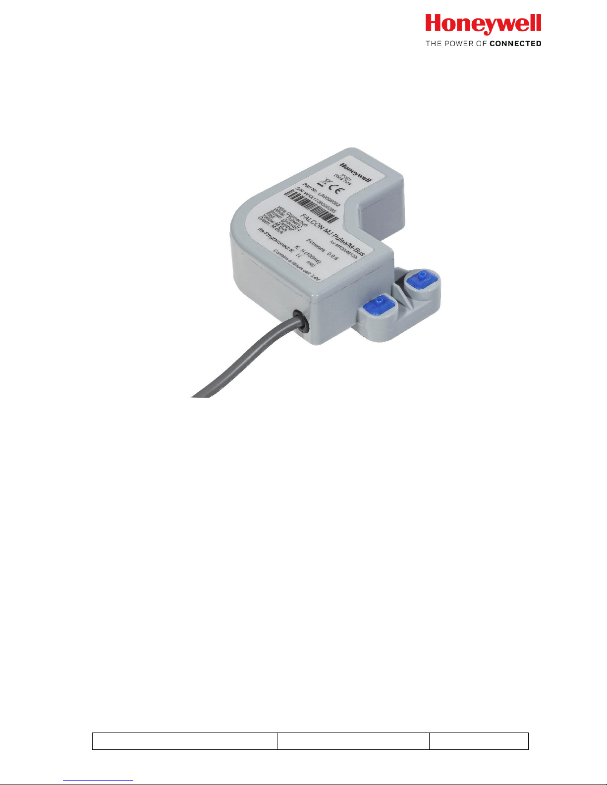
FALCON MJ Pulse/M-Bus communications module
Once the meter index is configured via the M-Bus, the Falcon MJ will transfer the exact meter
index shown on the water meter's register. The free of charge software MBCONF can be used
for parameterization. Because of its intuitive user interface, MBCONF is very simple to use.
Another feature of the Falcon MJ is its due date function. The user can program an annual due
date. In conjunction with the unit's real-time clock with calendar function, the meter's current
index will be specially stored on the configured date at 00:00 (change of day to the reporting
date). A write-protect function prevents pre-set values from being modified. This write protection
can be improved by using a password (optional).
Warning: If this password get lost, the write protection cannot be disabled anymore!
When the module is connected to a M-Bus network, the device gets its power from the M-Bus.
The internal battery backs up operation even when the M-Bus has an failure. The battery is
already activated when the unit is delivered.
The Falcon MJ stores the meter index on the first day of every month at 00:00.
The Falcon MJ offers two different telegram types which are selectable by the user: The long
telegram contains all values, including monthly values. The short telegram does not contain any
monthly values. Even though the short telegram type may be selected, monthly values are
stored internally and are available later on for read out if the telegram type is changed.
Page 3

Falcon MJ M-Bus Operating instructions
05/18 Generation 1.2
Page 3 of 38
2 Installation and commissioning
2.1 Installing Falcon MJ M-Bus
Refer to the separate installation instructions inside the package.
2.2 Connection
The Falcon MJ will be delivered with a permanently attached 5 wires cable, 3m length. The
yellow and green M-Bus wires can be connected with e.g. suitable distribution terminal strips.
The polarity of the M-Bus wires is irrelevant.
3 Configuration with MBCONF
This device's configuration must be adapted by the customer to the given meter. This can be
done, for example, with the program MBCONF, version 3.6 and higher, which will be described
below.
3.1 Installation
The MBCONF parameterization software for the Falcon MJ is a 32-bit application that can be
executed on an IBM compatible PC running a Windows 95 / 98 / XP / 7 / 10 operating system.
The desktop or laptop PC to be used must have a free USB interface connection. This interface
connection must be connected to an M-Bus level converter (MR003 USB / MikroMaster).
The Falcon MJ device which I configured must have a 1:1 connection (i.e. be the only M-Bus
device attached) to the M-Bus output of the level converter.
In order to install the software onto the PC, please execute the file
"MBCONF_SETUP.EXE" by selecting it from the Windows Explorer or via "Start – Run". The
setup program allows selection of a language during installation. If desired, a program group
and a desktop link can be created. Both language variations, German and English, can
thereafter be selected for execution from the Start menu or directly from the desktop link.
Page 4
Falcon MJ M-Bus Operating instructions
05/18 Generation 1.2
Page 4 of 38
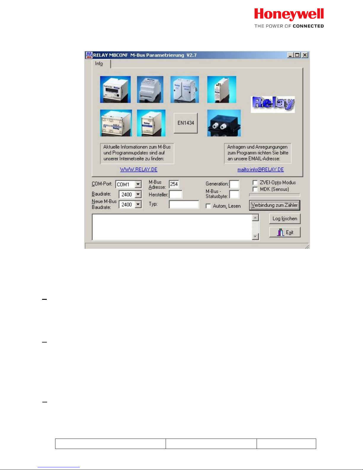
3.2 Info tab card
The lower third of this card is also visible in every other card. This makes the following entry
fields and control buttons continuously available:
COM-Port
specifies the serial interface of the PC to which the M-Bus level converter is
connected. This port setting will be stored in the program's INI file so that when
the program is restarted it will not be necessary to make this setting again.
Baudrate
specifies the PC's interface speed. It can be set to 300, 2400 and 9600 baud
and corresponds to the currently used M-Bus baudrate. The Falcon MJ module
supports the baud-rates 300, 2400 and 9600 WITH automatic detection, that
means the baud rate do not need to be configured and adopts automatically
to the baud rate of the M-Bus network.
New M-Bus baud-rate
permits a baud-rate changeover for the M-Bus device. To this end the
corresponding selection field is used to set a new baud-rate. Afterwards, the
module will be notified of the new baud-rate via the M-Bus.
Page 5

Falcon MJ M-Bus Operating instructions
05/18 Generation 1.2
Page 5 of 38
As the FALCON MJ module supports Auto-bauding a change of the M-Bus
speed is not required. The module will automatically detect the selected
baudrate of the M-Bus system
M-Bus address
is the primary M-Bus address for the attached M-Bus device. In a 1:1
connection (1 adapter on the M-Bus), the broadcast address 254 can be used.
Every M-Bus terminal device must respond to the address 254. The default
setting for this address in the program is 254.
Connect to meter
is a control button which requests data from the M-Bus terminal
device in conjunction with automatic device type recognition. The
fields "Manufacturer", "Generation", "Type" and "M-Bus status byte"
will be updated with the device's responses. Depending on the
manufacturer and type of M-Bus device, new tab cards will then be
created.
Manufacturer
is a field that, following a successful read ("Meter connection"), will
display a 3 character M-Bus manufacturer code (upper-case ASCII
letters).
Generation
displays the version of the connected M-Bus module's firmware.
Type
displays the device type of the connected device (here: Honeywell /
Elster Falcon MJ). This field cannot be edited (read only).
Status
displays the M-Bus status of the connected device.
ZVEI-Opto Mode
if this check-box is activated, devices with an optical interface which use the
EN1434-3 communications protocol can be read out and parameterized with
the help of an optical head (e.g. the PadPuls M4).
MDK (Sensus)
this check-box activates the read out of Sensus meters with the Mini-Bus
interface and special inductive heads (MDK).
Autom. readout
if this check-box is activated, the program will automatically re-read the
device's values after every write operation.
Page 6

Falcon MJ M-Bus Operating instructions
05/18 Generation 1.2
Page 6 of 38
Log window
The so-called "Log window" is always visible. All M-Bus communication
telegrams will be recorded in this window. Data will be displayed in
hexadecimal representation. Output in the log window can be marked and then
stored in the Windows clipboard with the "CTRL+C" key combination. From
the clipboard it is easy to paste the data into a text processing program for
documenting purposes. As soon as this window has reached its storage
capacity, no more data will be entered. The displayed data must be deleted in
order to allow recording to continue.
The following control buttons are also always visible:
Erase log deletes all output in the log window.
Exit terminates the program and writes the current setting for serial in-
terface selection into the INI file.
Page 7
Falcon MJ M-Bus Operating instructions
05/18 Generation 1.2
Page 7 of 38
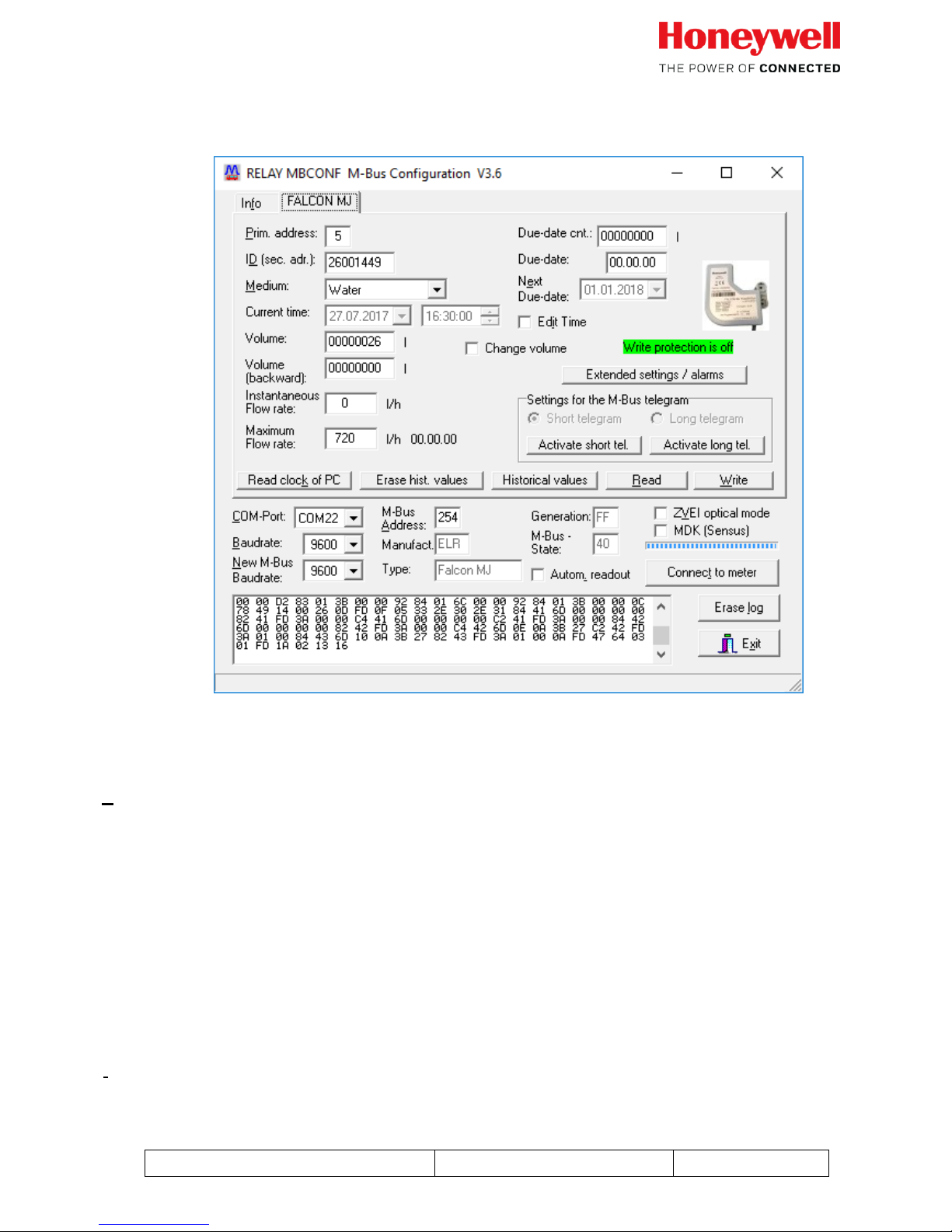
3.3 Falcon MJ tab card
This tab card shows the current settings and values for the Falcon MJ M-Bus. The entry fields
and control buttons, described below, permit device parameters to be changed:
Primary address
is the M-Bus address of the Falcon MJ. A value between 0 and 250 can be
entered into this field if the primary address needs to be changed. Click on
"Write" control button will transfer the primary address and other alterable
settings on this tab card to the Falcon MJ module. The addresses 253, 254
and 255 are broadcast addresses.
• 253 -> deselect all slaves
• 254 -> select all slaves
• 255 -> select all slaves without confirmation (0xE5).
ID (sec.adr.)
Page 8

Falcon MJ M-Bus Operating instructions
05/18 Generation 1.2
Page 8 of 38
is an 8-character M-Bus ID used for secondary addressing on the
Falcon MJ. We recommend that the serial number of the connected
water meter is programmed here.
Default: Secondary address is set as the last 8 digits of the module´s
SN
Medium
describes the medium to be measured on the selected Falcon MJ.
Selection: water, hot water, cold water, hot/cold water
Current time
is the current date and time inside the module This field can only be
edited, and changed in the module if the check-box "Edit Time" is
activated. The "Read clock of PC" control button will make a onetime
transfer of the PC's current time into this window. A click on the
control arrow at the right of the date field will open a calendar for
convenient selection of the date.
Edit Time
activation of this control check-box permits editing and programming of the
current date and time. This checkbox will automatically deactivate again after
parameterization has been done successfully.
Volume
is the current meter index in liters. By checking the box “Change volume” the
meter index can be updated.
Only possible if write protection is OFF and the “change volume” box is
checked.
Volume (backward)
is the meter count in litres for the amount of backflow
Change volume
activation of this check-box permits editing the "Volume" and "Volume
(backwards)" fields. This check-box will automatically deactivate again after
parameterization was done successfully.
Instantaneous Flow rate
displays the current flow in [l/h].
Page 9

Falcon MJ M-Bus Operating instructions
05/18 Generation 1.2
Page 9 of 38
Maximum Flow rate
displays the max flow rate registered by the module with the
according date.
The date will only be shown if the module is connected to the
M-Bus permanent. For quick read out via MBConf, use the
“Historical values” button to see the last monthly values and also
the last monthly max. flow values.
Erase hist. values
deletes all monthly values in the Falcon MJ module. I.e. historic monthly meter
index and historic max. flow rate values.
Historical values
displays all Falcon MJ stored monthly values in a pop-up window. This control
button is only active when the "Long telegram" radio button is active. This
control will also store values for maximum throughput of the day and the
month.
Read clock of PC
reads the PC system's current date and time and enters this data into the
"Current time" field.
Due-date cnt.
is the stored meter counter index for the Due date. This field cannot be edited
(read only).
Due-date
is the last reporting date (i.e. date when the meter index was stored the last
time) in the format DD.MM.YY. This field cannot be edited (read only).
Next due-date
is the next due date (i.e. date for the next storage of meter index) in the format
DD.MM.YY. Storing will take place at 00:00 on the due date, e.g. if next
reporting day is 01.01. then following a change from 31.12. 23:59 to 01.01. at
00:00. The field can only be edited when the check-box "Edit time" is activated.
ExtendedSettings / Warnings
opens a new tab card responsible for the configuration of alarms, pulse
outputs settings and other information (see section 3.4).
M-Bus telegram settings
displays the setting for telegram type effective for the Falcon MJ.
Page 10
Falcon MJ M-Bus Operating instructions
05/18 Generation 1.2
Page 10 of 38
Activate short tel.
switches the mode for the M-Bus protocol on the Falcon MJ to short-form
telegram (without monthly values)
Activate long tel.
switches the mode for M-Bus protocol on the Falcon MJ to long telegram (with
monthly values).
Read
updates M-Bus data on the selected tab card.
Write
sends the current settings to the device where they will be stored.
Notice:
If a new device is connected, the control button "Connect to meter" must first be pressed.
Afterwards the tab card of the Falcon MJ will be shown.
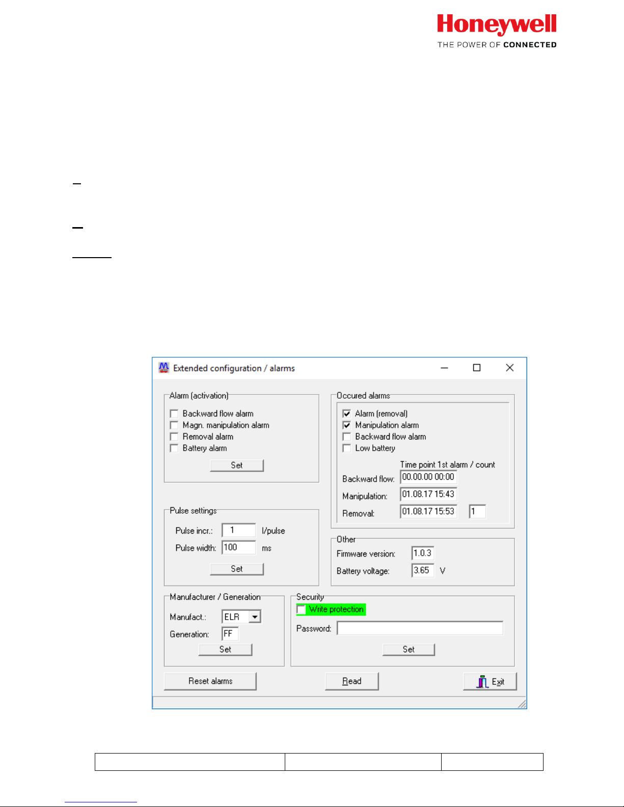
3.4 Extended configuration / alarms tab
Page 11

Falcon MJ M-Bus Operating instructions
05/18 Generation 1.2
Page 11 of 38
This tab card shows the currently set configuration for the Falcon MJ module. Functions can be
activated by marking respective check-boxes.
3.4.1 Alarm (Activation)
The alarm activation settings enables or disables the corresponding alarms via the Tamper
signal (red wire). The activation or deactivation of any alarm here does not influence the alarm
management via the M-Bus wire.
It is also possible to activate multiple alarms, shown on the tamper wire.
Attention: There is no differentiator via the tamper wire which alarm just occurs!
Backward flow alarm
is activated when more than 3 litres continuous backflow are
measured.
Magn. Manipulation alarm
is activated when a manipulation attempt with an external magnet is
detected.
Removal alarm
Is activated when the module is removed from the meter
Battery alarm
Is activated when the remaining lifetime of the battery is lower
than app. 13 months.
3.4.2 Occurred alarms
The occurred alarms are shown on the M-Bus when one of those alarms were detected earlier.
Alarm (removal)
Is activated when the module is removed from the meter. In addition
to the check box there is the date and time of the first appearance of
the alarm and also a counter how often the module was removed. The
removal alarm automatically sets a manipulation alarm as well.
Page 12

Falcon MJ M-Bus Operating instructions
05/18 Generation 1.2
Page 12 of 38
Manipulation alarm
Is activated when a magnetic manipulation attempt was detected. It is also
activated in combination with the removal alarm. A date and time is stored
for the first occurred alarm event.
Backward flow alarm
is activated when more than 3 litres continuous backflow are measured.
The date and time is stored for the first backflow event.
Low battery alarm
Is activated when the remaining lifetime of the battery is lower than
app. 13 months.
3.4.3 Pulse settings
Those two values reconfigure the compensated pulse output signal (wires White and brown)
White wire Pulse (+)
Brown wire Ground (-)
Max contact load: 30 V DC / 30mA
Default setting for pulse output: 1 litre per pulse; 100ms pulse width
For the pulse output an open drain is used. The polarity must be observed.
The pulse output is compatible to the most systems that were used with a Reed-switch before
Pulse incr.
Specifies the pulse output resolution in litres per pulses. All full
values between 1 and 1000 liters are possible.
Dosing applications: For special dosing applications, you can enter
the value 9999. This value will give a pulse output of 2,5 litres per
pulse!
Pulse width
The pulse width can be set between 50 and 500 ms. The setting of
pulse incr. and pulse width must be plausible, depending on the
meter size and max flow rate values.
Example: For a Q3 10; DN25 meter with a Q4 value of 12,5 m³/h
12,5m³/h app. 3,5 l/s
Pulse output 1 litre max. possible pulse width 140 ms (smaller
values are possible)
If a pulse overcount would happen, the pulser stores the pulses and
sends them to the output when the flow rate decreases again. The
internal storage for this pulse counter is 65.535 pulses.
Page 13

Falcon MJ M-Bus Operating instructions
05/18 Generation 1.2
Page 13 of 38
3.4.4 Manufacturer / generation
The manufacturer and generation identifiers of the Falcon MJ module can be changed.
For the manufacturer, the following manufacturer codes are possible:
ELR; ELS; EMT; HON
This possibility allows the customer to set up the identification of the module according
the DIN 43863-5 meter serial numbers
3.4.5 Other
Firmware version
Here you find the current firmware version of the Falcon MJ module. The firmware
version can also be found on the sticker on the top of the module.
Battery voltage
Indicates the level of the battery voltage. A new module should show app. 3.6 V
3.4.6 Security
The security settings enable or disables the write protection setting. With activated write
protection, values like the meter index or due date values cannot be changed anymore.
In addition, there is the possibility to protect the write protection with an additional
password. The password can be max. 32 signs long.
Use of Password to activate write protection:
Enter a password with max. 32 signs. Check the write protection box and press
the “set” button below.
Use of Password to deactivate write protection:
Enter the password you chose when you activated the write protection. Untick the
write protection checkbox and press “Set” again to deactivate the write protection.
ATTENTION: If you secure the write protection with a password and it got lost, you
are not able to deactivate the write protection anymore!
Page 14

Falcon MJ M-Bus Operating instructions
05/18 Generation 1.2
Page 14 of 38
The following control buttons are also always visible:
Read
updates M-Bus data on the selected tab card. Even fields which
cannot be modified will be updated.
Exit
Close the extended configuration/alarm tab
Reset alarms
All stored alarms will be cleared to “0”
Page 15

Falcon MJ M-Bus Operating instructions
05/18 Generation 1.2
Page 15 of 38
4 M-Bus telegrams
4.1 SND_UD: Send User data; telegram selection
4.1.1 Select Normal readout (Short telegram)
SND-UD (M-Bus)
OMS M-Bus frame
Water meter example
Layer
Byte No
Field Name
Content
Bytes [hex]
plain
1
Start
Start byte
68h
Data Link Layer
(DLL)
2
L Field
Length of data (xx bytes)
xxh
3
L Field
Length of data (xx bytes)
xxh
4
Start
Start byte
68h
5
C Field
Send user data
53h
6
A-Field
Secondary addressing mode
FDh
7
CI Field
Application Select (long Header)
53h
Transport Layer (TPL)
8
Ident.Nr.
Ident No LSB (BCD)
78h
9
Ident.Nr.
Ident No (BCD)
56h
10
Ident.Nr.
Ident No (BCD) (=12345678)
34h
11
Ident.Nr.
Ident No MSB (BCD)
12h
12
Manufr
Manufacturer code
92h
13
Manufr
Manufacturer code
15h
14
Version
Version (or Generation number)
B1h
15
Device type
Device type (Medium=Water)
07h
16
Access No.
Access number of Meter
2Ah
17
Status
M-Bus state
00h
18
Config Field
no Encryption
00h
19
Config Field
no Encryption
00h
20
Subcode
20h
21
Checksum xxh
DLL
22
Stop
Stop byte
16h
Page 16

Falcon MJ M-Bus Operating instructions
05/18 Generation 1.2
Page 16 of 38
4.1.2 Select Enhanced readout (Long telegram)
SND-UD (M-Bus)
OMS M-Bus frame
Water meter example
Layer
Byte No
Field Name
Content
Bytes [hex]
plain
1
Start
Start byte
68h
Data Link Layer
(DLL)
2
L Field
Length of data (xx bytes)
xxh
3
L Field
Length of data (xx bytes)
xxh
4
Start
Start byte
68h
5
C Field
Send user data
53h
6
A-Field
Secondary addressing mode
FDh
7
CI Field
Application Select (long Header)
53h
Transport Layer (TPL)
8
Ident.Nr.
Ident No LSB (BCD)
78h
9
Ident.Nr.
Ident No (BCD)
56h
10
Ident.Nr.
Ident No (BCD) (=12345678)
34h
11
Ident.Nr.
Ident No MSB (BCD)
12h
12
Manufr
Manufacturer code
92h
13
Manufr
Manufacturer code
15h
14
Version
Version (or Generation number)
B1h
15
Device type
Device type (Medium=Water)
07h
16
Access No.
Access number of Meter
2Ah
17
Status
M-Bus state
00h
18
Config Field
no Encryption
00h
19
Config Field
no Encryption
00h
20
Subcode
30h
21
Checksum xxh
DLL
22
Stop
Stop byte
16h
Page 17

Falcon MJ M-Bus Operating instructions
05/18 Generation 1.2
Page 17 of 38
4.2 RSP_UD: data transfer on request
4.2.1 Short – telegram (for Modules with Firmware 1.0.3 or older)
OMS M-Bus frame
Water
meter
example
Layer
Byte No
Field Name
Content
Bytes
[hex]
plain
1
Start
Start byte
68h
Data Link Layer
(DLL)
2
L Field
Length of data (xx bytes)
xxh
3
L Field
Length of data (xx bytes)
xxh
4
Start
Start byte
68h
5
C Field
Respond user data
08h
6
A-Field
Secondary addressing mode
FDh
7
CI Field
72h (long header)
72h
Transport Layer (TPL)
8
Ident.Nr.
Ident No LSB (BCD)
78h
9
Ident.Nr.
Ident No (BCD)
56h
10
Ident.Nr.
Ident No (BCD) (=12345678)
34h
11
Ident.Nr.
Ident No MSB (BCD)
12h
12
Manufr
Manufacturer code
92h
13
Manufr
Manufacturer code
15h
14
Version
Version (or Generation number)
xxh
15
Device type
Device type (Medium=Water)
07h
16
Access No.
Access number of Meter
2Ah
17
Status
M-Bus state
00h
18
Config Field
no Encryption
00h
19
Config Field
no Encryption
00h
20
DR1
DIF (8 digit BCD)
0Ch
Application Layer (APL)
21
DR1
VIF (Volume l)
13h
22
DR1
Value LSB
73h
23
DR1
Value
42h
24
DR1
Value ( = 28504,273 m³)
50h
25
DR1
Value MSB
28h
26
DR2
DIF (Time at readout; Type F)
04h
27
DR2
VIF (Date, Time)
6Dh
28
DR2
Value LSB
32h
29
DR2
Value
37h
30
DR2
Value ( 31.05.2008 23:50 )
1Fh
31
DR2
Value MSB
15h
32
DR3
DIF (Date Stor. 1;Type G)
42h
33
DR3
VIF (Date)
6Ch
Page 18

Falcon MJ M-Bus Operating instructions
05/18 Generation 1.2
Page 18 of 38
34
DR3
Value
xxh
35
DR3
Value
xxh
36
DR4
DIF (8 digit BCD Stor. 1)
4Ch
37
DR4
VIF (Volume l)
13h
38
DR4
Value LSB
78h
39
DR4
Value
56h
40
DR4
Value ( = 12345,678 m³)
34h
41
DR4
Value MSB
12h
42
DR5
DIF (Date Stor. 1;Type G)
42h
43
DR5
VIF (Date + Extension)
ECh
44
DR5
VIFE (Future Value)
7Eh
45
DR5
Value
xxh
46
DR5
Value
xxh
47
DR6
DIF (8 digit BCD)
0Ch
48
DR6
VIF (Volume l + Extension)
93h
49
DR6
VIFE (backward flow)
3Ch
50
DR6
Value LSB
03h
51
DR6
Value
00h
52
DR6
Value ( = 0,003 m³)
00h
53
DR6
Value MSB
00h
54
DR7
DIF (Date Max. Value; Type G)
12h
55
DR7
VIF (Date)
6Ch
56
DR7
Value
xxh
57
DR7
Value
xxh
58
DR8
DIF (16 bit Int, Max. Value)
12h
59
DR8
VIF (Flow Rate l/h)
3Bh
60
DR8
Value
xxh
61
DR8
Value
xxh
62
DR9
DIF (16 Bit Int)
02h
63
DR9
VIF (Flow Rate l/h)
3Bh
64
DR9
Value
xxh
65
DR9
Value
xxh
66
DR10
DIF (Backflow Alarm Date; Type F)
C4h
67
DR10
DIFE (Storage No. 7)
03h
68
DR10
VIF (Date, Time)
6Dh
69
DR10
Value LSB
xxh
70
DR10
Value
xxh
71
DR10
Value
xxh
72
DR10
Value MSB
xxh
73
DR11
DIF (Manipulation Alarm Date; Type F)
84h
74
DR11
DIFE (Storage No. 6)
03h
75
DR11
VIF (Date, Time)
6Dh
76
DR11
Value LSB
xxh
77
DR11
Value
xxh
78
DR11
Value
xxh
79
DR11
Value MSB
xxh
Page 19

Falcon MJ M-Bus Operating instructions
05/18 Generation 1.2
Page 19 of 38
80
DR12
DIF (Manufacturerspecific)
0Fh
81
DR12
PBIT
xxh
82
Checksum
xxh
DLL
83
Stop
Stop byte
16h
4.2.2 Long – telegram (for Modules with Firmware 1.0.3 or older)
Long telegram with monthly values.
Frame 1:
RSP-UD (M-Bus)
OMS M-Bus frame
Meter
example
Layer
Byte No
Field Name
Content
Bytes
[hex]
1
Start
Start byte
68h
Data Link Layer
(DLL)
2
L Field
Length of data (xx bytes)
xxh
3
L Field
Length of data (xx bytes)
xxh
4
Start
Start byte
68h
5
C Field
Respond user data
08h
6
A-Field
Secondary addressing mode
FDh
7
CI Field
72h (long header)
72h
Transport Layer (TPL)
8
Ident.Nr.
Ident No LSB (BCD)
78h
9
Ident.Nr.
Ident No (BCD)
56h
10
Ident.Nr.
Ident No (BCD) (=12345678)
34h
11
Ident.Nr.
Ident No MSB (BCD)
12h
12
Manufr
Manufacturer code
92h
13
Manufr
Manufacturer code
15h
14
Version
Version (or Generation number)
xxh
15
Device type
Device type (Medium=Water)
07h
16
Access No.
Access number of Meter
2Ah
17
Status
M-Bus state
00h
18
Config Field
no Encryption
00h
19
Config Field
no Encryption
00h
20
DR1
DIF (8 digit BCD)
0Ch
Application Layer (APL)
21
DR1
VIF (Volume l)
13h
22
DR1
Value LSB
73h
23
DR1
Value
42h
24
DR1
Value ( = 28504,273 m³)
50h
25
DR1
Value MSB
28h
26
DR2
DIF (Time at readout; Type F)
04h
27
DR2
VIF (Date, Time)
6Dh
28
DR2
Value LSB
32h
Page 20

Falcon MJ M-Bus Operating instructions
05/18 Generation 1.2
Page 20 of 38
29
DR2
Value
37h
30
DR2
Value ( 31.05.2008 23:50 )
1Fh
31
DR2
Value MSB
15h
32
DR3
DIF (Date Stor. 1;Type G)
42h
33
DR3
VIF (Date)
6Ch
34
DR3
Value
xxh
35
DR3
Value
xxh
36
DR4
DIF (8 digit BCD Stor. 1)
4Ch
37
DR4
VIF (Volume l)
13h
38
DR4
Value LSB
78h
39
DR4
Value
56h
40
DR4
Value ( = 12345,678 m³)
34h
41
DR4
Value MSB
12h
42
DR5
DIF (Date Stor. 1;Type G)
42h
43
DR5
VIF (Date + Extension)
ECh
44
DR5
VIFE (Future Value)
7Eh
45
DR5
Value
xxh
46
DR5
Value
xxh
47
DR6
DIF (8 digit BCD)
0Ch
48
DR6
VIF (Volume l + Extension)
93h
49
DR6
VIFE (backward flow)
3Ch
50
DR6
Value LSB
03h
51
DR6
Value
00h
52
DR6
Value ( = 0,003 m³)
00h
53
DR6
Value MSB
00h
54
DR7
DIF (Date Max. Value; Type G)
12h
55
DR7
VIF (Date)
6Ch
56
DR7
Value
xxh
57
DR7
Value
xxh
58
DR8
DIF (16 bit Int, Max. Value)
12h
59
DR8
VIF (Flow Rate l/h)
3Bh
60
DR8
Value
xxh
61
DR8
Value
xxh
62
DR9
DIF (16 Bit Int)
02h
63
DR9
VIF (Flow Rate l/h)
3Bh
64
DR9
Value
xxh
65
DR9
Value
xxh
66
DR10
DIF (Backflow Alarm Date; Type F)
C4h
67
DR10
DIFE (Storage No. 7)
03h
68
DR10
VIF (Date, Time)
6Dh
69
DR10
Value LSB
xxh
70
DR10
Value
xxh
71
DR10
Value
xxh
72
DR10
Value MSB
xxh
73
DR11
DIF (Manipulation Alarm Date; Type F)
84h
74
DR11
DIFE (Storage No. 6)
03h
Page 21

Falcon MJ M-Bus Operating instructions
05/18 Generation 1.2
Page 21 of 38
75
DR11
VIF (Date, Time)
6Dh
76
DR11
Value LSB
xxh
77
DR11
Value
xxh
78
DR11
Value
xxh
79
DR11
Value MSB
xxh
80
DR12
DIF (2 digit BCD + Extension)
89h
81
DR12
DIFE (Storagenumber 8)
04h
82
DR12
VIF (Second Extensio table)
FDh
83
DR12
VIFE (Size of storage block)
22h
84
DR12
Value (13)
13h
85
DR13
DIF (2 digit BCD + Extension)
89h
86
DR13
DIFE (Storagenumber 8)
04h
87
DR13
VIF (Second Extensio table)
FDh
88
DR13
VIFE (Storage intervall month)
28h
89
DR13
Value (1)
01h
90
DR14
DIF (16 bit Int. + Ext.)
82h
91
DR14
DIFE (Storagenumber 20)
0Ah
92
DR14
VIF (Date Type G)
6Ch
93
DR14
Value LSB
xxh
94
DR14
Value MSB
xxh
95
DR15
DIF (8 digit BCD + Ext.)
8Ch
96
DR15
DIFE (Storagenumber 8)
04h
97
DR15
VIF (Volume l)
13h
98
DR15
Value LSB
xxh
99
DR15
Value
xxh
100
DR15
Value
xxh
101
DR15
Value MSB
xxh
102
DR16
DIF (8 digit BCD + Ext.)
CCh
103
DR16
DIFE (Storagenumber 9)
04h
104
DR16
VIF (Volume l)
13h
105
DR16
Value LSB
xxh
106
DR16
Value
xxh
107
DR16
Value
xxh
108
DR16
Value MSB
xxh
109
DR17
DIF (8 digit BCD + Ext.)
8Ch
110
DR17
DIFE (Storagenumber 10)
05h
111
DR17
VIF (Volume l)
13h
112
DR17
Value LSB
xxh
113
DR17
Value
xxh
114
DR17
Value
xxh
115
DR17
Value MSB
xxh
116
DR18
DIF (8 digit BCD + Ext.)
CCh
117
DR18
DIFE (Storagenumber 11)
05h
118
DR18
VIF (Volume l)
13h
119
DR18
Value LSB
xxh
120
DR18
Value
xxh
Page 22

Falcon MJ M-Bus Operating instructions
05/18 Generation 1.2
Page 22 of 38
121
DR18
Value
xxh
122
DR18
Value MSB
xxh
123
DR19
DIF (8 digit BCD + Ext.)
8Ch
124
DR19
DIFE (Storagenumber 12)
06h
125
DR19
VIF (Volume l)
13h
126
DR19
Value LSB
xxh
127
DR19
Value
xxh
128
DR19
Value
xxh
129
DR19
Value MSB
xxh
130
DR20
DIF (8 digit BCD + Ext.)
CCh
131
DR20
DIFE (Storagenumber 13)
06h
132
DR20
VIF (Volume l)
13h
133
DR20
Value LSB
xxh
134
DR20
Value
xxh
135
DR20
Value
xxh
136
DR20
Value MSB
xxh
137
DR21
DIF (8 digit BCD + Ext.)
8Ch
138
DR21
DIFE (Storagenumber 14)
07h
139
DR21
VIF (Volume l)
13h
140
DR21
Value LSB
xxh
141
DR21
Value
xxh
142
DR21
Value
xxh
143
DR21
Value MSB
xxh
144
DR22
DIF (8 digit BCD + Ext.)
CCh
145
DR22
DIFE (Storagenumber 15)
07h
146
DR22
VIF (Volume l)
13h
147
DR22
Value LSB
xxh
148
DR22
Value
xxh
149
DR22
Value
xxh
150
DR22
Value MSB
xxh
151
DR23
DIF (8 digit BCD + Ext.)
8Ch
152
DR23
DIFE (Storagenumber 16)
08h
153
DR23
VIF (Volume l)
13h
154
DR23
Value LSB
xxh
155
DR23
Value
xxh
156
DR23
Value
xxh
157
DR23
Value MSB
xxh
158
DR24
DIF (8 digit BCD + Ext.)
CCh
159
DR24
DIFE (Storagenumber 17)
08h
160
DR24
VIF (Volume l)
13h
161
DR24
Value LSB
xxh
162
DR24
Value
xxh
163
DR24
Value
xxh
164
DR24
Value MSB
xxh
165
DR25
DIF (8 digit BCD + Ext.)
8Ch
166
DR25
DIFE (Storagenumber 18)
09h
Page 23

Falcon MJ M-Bus Operating instructions
05/18 Generation 1.2
Page 23 of 38
167
DR25
VIF (Volume l)
13h
168
DR25
Value LSB
xxh
169
DR25
Value
xxh
170
DR25
Value
xxh
171
DR25
Value MSB
xxh
172
DR26
DIF (8 digit BCD + Ext.)
CCh
173
DR26
DIFE (Storagenumber 19)
09h
174
DR26
VIF (Volume l)
13h
175
DR26
Value LSB
xxh
176
DR26
Value
xxh
177
DR26
Value
xxh
178
DR26
Value MSB
xxh
179
DR27
DIF (8 digit BCD + Ext.)
8Ch
180
DR27
DIFE (Storagenumber 20)
0Ah
181
DR27
VIF (Volume l)
13h
182
DR27
Value LSB
xxh
183
DR27
Value
xxh
184
DR27
Value
xxh
185
DR27
Value MSB
xxh
186
DR28
DIF (Manufacturer specific + Frame)
1Fh
187
DR28
PBIT
xxh
188
Checksum
xxh
DLL
189
Stop
Stop byte
16h
Frame 2:
RSP-UD (M-Bus)
OMS M-Bus frame
Meter
example
Layer
Byte No
Field Name
Content
Bytes
[hex]
1
Start
Start byte
68h
Data Link Layer
(DLL)
2
L Field
Length of data (xx bytes)
xxh
3
L Field
Length of data (xx bytes)
xxh
4
Start
Start byte
68h
5
C Field
Respond user data
08h
6
A-Field
Secondary addressing mode
FDh
7
CI Field
72h (long header)
72h
Transport
Layer
(TPL)
8
Ident.Nr.
Ident No LSB (BCD)
78h
9
Ident.Nr.
Ident No (BCD)
56h
10
Ident.Nr.
Ident No (BCD) (=12345678)
34h
11
Ident.Nr.
Ident No MSB (BCD)
12h
12
Manufr
Manufacturer code
92h
Page 24

Falcon MJ M-Bus Operating instructions
05/18 Generation 1.2
Page 24 of 38
13
Manufr
Manufacturer code
15h
14
Version
Version (or Generation number)
xxh
15
Device type
Device type (Medium=Water)
07h
16
Access No.
Access number of Meter
2Ah
17
Status
M-Bus state
00h
18
Config Field
no Encryption
00h
19
Config Field
no Encryption
00h
20
DR29
DIF (16 bit Int. + max Val. + Extension)
92h
Application Layer (APL)
21
DR29
DIFE (Storagenumber 28)
0Eh
22
DR29
VIF (Date Type G)
6Ch
23
DR29
Value
xxh
24
DR29
Value
xxh
25
DR30
DIF (16 bit Int. + max Val. + Extension)
92h
26
DR30
DIFE (Storagenumber 28)
0Eh
27
DR30
VIF (Volume flow [l/h])
3Bh
28
DR30
Value
xxh
29
DR30
Value
xxh
30
DR31
DIF (16 bit Int. + max Val. + Extension)
D2h
31
DR31
DIFE (Storagenumber 29)
0Eh
32
DR31
VIF (Date Type G)
6Ch
33
DR31
Value
xxh
34
DR31
Value
xxh
35
DR32
DIF (16 bit Int. + max Val. + Extension)
D2h
36
DR32
DIFE (Storagenumber 29)
0Eh
37
DR32
VIF (Volume flow [l/h])
3Bh
38
DR32
Value
xxh
39
DR32
Value
xxh
40
DR33
DIF (16 bit Int. + max Val. + Extension)
92h
41
DR33
DIFE (Storagenumber 30)
0Fh
42
DR33
VIF (Date Type G)
6Ch
43
DR33
Value
xxh
44
DR33
Value
xxh
45
DR34
DIF (16 bit Int. + max Val. + Extension)
92h
46
DR34
DIFE (Storagenumber 30)
0Fh
47
DR34
VIF (Volume flow [l/h])
3Bh
48
DR34
Value
xxh
49
DR34
Value
xxh
50
DR35
DIF (16 bit Int. + max Val. + Extension)
D2h
51
DR35
DIFE (Storagenumber 31)
0Fh
52
DR35
VIF (Date Type G)
6Ch
53
DR35
Value
xxh
54
DR35
Value
xxh
55
DR36
DIF (16 bit Int. + max Val. + Extension)
D2h
56
DR36
DIFE (Storagenumber 31)
0Fh
57
DR36
VIF (Volume flow [l/h])
3Bh
58
DR36
Value
xxh
Page 25

Falcon MJ M-Bus Operating instructions
05/18 Generation 1.2
Page 25 of 38
59
DR36
Value
xxh
60
DR37
DIF (16 bit Int. + max Val. + Extension)
92h
61
DR37
DIFE (Extension)
80h
62
DR37
DIFE (Storagenumber 32)
01h
63
DR37
VIF (Date Type G)
6Ch
64
DR37
Value
xxh
65
DR37
Value
xxh
66
DR38
DIF (16 bit Int. + max Val. + Extension)
92h
67
DR38
DIFE (Extension)
80h
68
DR38
DIFE (Storagenumber 32)
01h
69
DR38
VIF (Volume flow [l/h])
3Bh
70
DR38
Value
xxh
71
DR38
Value
xxh
72
DR39
DIF (16 bit Int. + max Val. + Extension)
D2h
73
DR39
DIFE (Extension)
80h
74
DR39
DIFE (Storagenumber 33)
01h
75
DR39
VIF (Date Type G)
6Ch
76
DR39
Value
xxh
77
DR39
Value
xxh
78
DR40
DIF (16 bit Int. + max Val. + Extension)
D2h
79
DR40
DIFE (Extension)
80h
80
DR40
DIFE (Storagenumber 33)
01h
81
DR40
VIF (Volume flow [l/h])
3Bh
82
DR40
Value
xxh
83
DR40
Value
xxh
84
DR41
DIF (16 bit Int. + max Val. + Extension)
92h
85
DR41
DIFE (Extension)
81h
86
DR41
DIFE (Storagenumber 34)
01h
87
DR41
VIF (Date Type G)
6Ch
88
DR41
Value
xxh
89
DR41
Value
xxh
90
DR42
DIF (16 bit Int. + max Val. + Extension)
92h
91
DR42
DIFE (Extension)
81h
92
DR42
DIFE (Storagenumber 34)
01h
93
DR42
VIF (Volume flow [l/h])
3Bh
94
DR42
Value
xxh
95
DR42
Value
xxh
96
DR43
DIF (16 bit Int. + max Val. + Extension)
D2h
97
DR43
DIFE (Extension)
81h
98
DR43
DIFE (Storagenumber 35)
01h
99
DR43
VIF (Date Type G)
6Ch
100
DR43
Value
xxh
101
DR43
Value
xxh
102
DR44
DIF (16 bit Int. + max Val. + Extension)
D2h
103
DR44
DIFE (Extension)
81h
104
DR44
DIFE (Storagenumber 35)
01h
Page 26

Falcon MJ M-Bus Operating instructions
05/18 Generation 1.2
Page 26 of 38
105
DR44
VIF (Volume flow [l/h])
3Bh
106
DR44
Value
xxh
107
DR44
Value
xxh
108
DR45
DIF (16 bit Int. + max Val. + Extension)
92h
109
DR45
DIFE (Extension)
82h
110
DR45
DIFE (Storagenumber 36)
01h
111
DR45
VIF (Date Type G)
6Ch
112
DR45
Value
xxh
113
DR45
Value
xxh
114
DR46
DIF (16 bit Int. + max Val. + Extension)
92h
115
DR46
DIFE (Extension)
82h
116
DR46
DIFE (Storagenumber 36)
01h
117
DR46
VIF (Volume flow [l/h])
3Bh
118
DR46
Value
xxh
119
DR46
Value
xxh
120
DR47
DIF (16 bit Int. + max Val. + Extension)
D2h
121
DR47
DIFE (Extension)
82h
122
DR47
DIFE (Storagenumber 37)
01h
123
DR47
VIF (Date Type G)
6Ch
124
DR47
Value
xxh
125
DR47
Value
xxh
126
DR48
DIF (16 bit Int. + max Val. + Extension)
D2h
127
DR48
DIFE (Extension)
82h
128
DR48
DIFE (Storagenumber 37)
01h
129
DR48
VIF (Volume flow [l/h])
3Bh
130
DR48
Value
xxh
131
DR48
Value
xxh
132
DR49
DIF (16 bit Int. + max Val. + Extension)
92h
133
DR49
DIFE (Extension)
83h
134
DR49
DIFE (Storagenumber 38)
01h
135
DR49
VIF (Date Type G)
6Ch
136
DR49
Value
xxh
137
DR49
Value
xxh
138
DR50
DIF (16 bit Int. + max Val. + Extension)
92h
139
DR50
DIFE (Extension)
83h
140
DR50
DIFE (Storagenumber 38)
01h
141
DR50
VIF (Volume flow [l/h])
3Bh
142
DR50
Value
xxh
143
DR50
Value
xxh
144
DR51
DIF (16 bit Int. + max Val. + Extension)
D2h
145
DR51
DIFE (Extension)
83h
146
DR51
DIFE (Storagenumber 39)
01h
147
DR51
VIF (Date Type G)
6Ch
148
DR51
Value
xxh
149
DR51
Value
xxh
150
DR52
DIF (16 bit Int. + max Val. + Extension)
D2h
Page 27

Falcon MJ M-Bus Operating instructions
05/18 Generation 1.2
Page 27 of 38
151
DR52
DIFE (Extension)
83h
152
DR52
DIFE (Storagenumber 39)
01h
153
DR52
VIF (Volume flow [l/h])
3Bh
154
DR52
Value
xxh
155
DR52
Value
xxh
156
DR53
DIF (16 bit Int. + max Val. + Extension)
92h
157
DR53
DIFE (Extension)
80h
158
DR53
DIFE (Storagenumber 40)
01h
159
DR53
VIF (Date Type G)
6Ch
160
DR53
Value
xxh
161
DR53
Value
xxh
162
DR54
DIF (16 bit Int. + max Val. + Extension)
92h
163
DR54
DIFE (Extension)
80h
164
DR54
DIFE (Storagenumber 40)
01h
165
DR54
VIF (Volume flow [l/h])
3Bh
166
DR54
Value
xxh
167
DR54
Value
xxh
168
Checksum
xxh
DLL
169
Stop
Stop byte
16h
Page 28

Falcon MJ M-Bus Operating instructions
05/18 Generation 1.2
Page 28 of 38
4.2.3 Short – telegram (for Modules with Firmware 1.0.5 or newer)
OMS M-Bus frame
Water meter
example
Layer
Byte No
Field Name
Content
Bytes [hex]
plain
1
Start
Start byte
68h
Data Link Layer
(DLL)
2
L Field
Length of data (xx bytes)
xxh
3
L Field
Length of data (xx bytes)
xxh
4
Start
Start byte
68h
5
C Field
Respond user data
08h
6
A-Field
Secondary addressing mode
FDh
7
CI Field
72h (long header)
72h
Transport Layer (TPL)
8
Ident.Nr.
Ident No LSB (BCD)
78h
9
Ident.Nr.
Ident No (BCD)
56h
10
Ident.Nr.
Ident No (BCD) (=12345678)
34h
11
Ident.Nr.
Ident No MSB (BCD)
12h
12
Manufr
Manufacturer code
92h
13
Manufr
Manufacturer code
15h
14
Version
Version (or Generation number)
xxh
15
Device type
Device type (Medium=Water)
07h
16
Access No.
Access number of Meter
2Ah
17
Status
M-Bus state
00h
18
Config Field
no Encryption
00h
19
Config Field
no Encryption
00h
20
DR1
DIF (8 digit BCD)
0Ch
Application Layer (APL)
21
DR1
VIF (Volume l)
13h
22
DR1
Value LSB
73h
23
DR1
Value
42h
24
DR1
Value ( = 28504,273 m³)
50h
25
DR1
Value MSB
28h
26
DR2
DIF (Time at readout; Type F)
04h
27
DR2
VIF (Date, Time)
6Dh
28
DR2
Value LSB
32h
29
DR2
Value
37h
30
DR2
Value ( 31.05.2008 23:50 )
1Fh
31
DR2
Value MSB
15h
32
DR3
DIF (Date Stor. 1;Type G)
42h
33
DR3
VIF (Date)
6Ch
34
DR3
Value
xxh
35
DR3
Value
xxh
36
DR4
DIF (8 digit BCD Stor. 1)
4Ch
37
DR4
VIF (Volume l)
13h
38
DR4
Value LSB
78h
39
DR4
Value
56h
Page 29

Falcon MJ M-Bus Operating instructions
05/18 Generation 1.2
Page 29 of 38
40
DR4
Value ( = 12345,678 m³)
34h
41
DR4
Value MSB
12h
42
DR5
DIF (Date Stor. 1;Type G)
42h
43
DR5
VIF (Date + Extension)
ECh
44
DR5
VIFE (Future Value)
7Eh
45
DR5
Value
xxh
46
DR5
Value
xxh
47
DR6
DIF (8 digit BCD)
0Ch
48
DR6
VIF (Volume l + Extension)
93h
49
DR6
VIFE (backward flow)
3Ch
50
DR6
Value LSB
03h
51
DR6
Value
00h
52
DR6
Value ( = 0,003 m³)
00h
53
DR6
Value MSB
00h
54
DR7
DIF (Date Max. Value; Type G)
12h
55
DR7
VIF (Date)
6Ch
56
DR7
Value
xxh
57
DR7
Value
xxh
58
DR8
DIF (32 bit Int, Max. Value)
14h
59
DR8
VIF (Flow Rate l/h)
3Bh
60
DR8
Value
xxh
61
DR8
Value
xxh
62
DR8
Value
xxh
63
DR8
Value
xxh
64
DR9
DIF (32 Bit Int)
04h
65
DR9
VIF (Flow Rate l/h)
3Bh
66
DR9
Value
xxh
67
DR9
Value
xxh
68
DR9
Value
xxh
69
DR9
Value
xxh
70
DR10
DIF (Backflow Alarm Date; Type F)
C4h
71
DR10
DIFE (Storage No. 7)
03h
72
DR10
VIF (Date, Time)
6Dh
73
DR10
Value LSB
xxh
74
DR10
Value
xxh
75
DR10
Value
xxh
76
DR10
Value MSB
xxh
77
DR11
DIF (Manipulation Alarm Date; Type F)
84h
78
DR11
DIFE (Storage No. 6)
03h
79
DR11
VIF (Date, Time)
6Dh
80
DR11
Value LSB
xxh
81
DR11
Value
xxh
82
DR11
Value
xxh
83
DR11
Value MSB
xxh
84
DR12
DIF (Manufacturerspecific)
0Fh
85
DR12
PBIT
xxh
86
Checksum xxh
DLL
87
Stop
Stop byte
16h
Page 30

Falcon MJ M-Bus Operating instructions
05/18 Generation 1.2
Page 30 of 38
4.2.4 Long – telegram (for Modules with Firmware 1.0.5 or newer)
Long telegram with monthly values.
Frame 1:
RSP-UD (M-Bus)
OMS M-Bus frame
Water meter example
Layer
Byte No
Field Name
Content
Bytes [hex]
plain
1
Start
Start byte
68h
Data Link Layer
(DLL)
2
L Field
Length of data (xx bytes)
xxh
3
L Field
Length of data (xx bytes)
xxh
4
Start
Start byte
68h
5
C Field
Respond user data
08h
6
A-Field
Secondary addressing mode
FDh
7
CI Field
72h (long header)
72h
Transport
Layer (TPL)
8
Ident.Nr.
Ident No LSB (BCD)
78h
9
Ident.Nr.
Ident No (BCD)
56h
10
Ident.Nr.
Ident No (BCD) (=12345678)
34h
11
Ident.Nr.
Ident No MSB (BCD)
12h
12
Manufr
Manufacturer code
92h
13
Manufr
Manufacturer code
15h
14
Version
Version (or Generation number)
xxh
15
Device type
Device type (Medium=Water)
07h
16
Access No.
Access number of Meter
2Ah
17
Status
M-Bus state
00h
18
Config Field
no Encryption
00h
19
Config Field
no Encryption
00h
20
DR1
DIF (8 digit BCD)
0Ch
Application Layer (APL)
21
DR1
VIF (Volume l)
13h
22
DR1
Value LSB
73h
23
DR1
Value
42h
24
DR1
Value ( = 28504,273 m³)
50h
25
DR1
Value MSB
28h
26
DR2
DIF (Time at readout; Type F)
04h
27
DR2
VIF (Date, Time)
6Dh
28
DR2
Value LSB
32h
29
DR2
Value
37h
30
DR2
Value ( 31.05.2008 23:50 )
1Fh
31
DR2
Value MSB
15h
32
DR3
DIF (Date Stor. 1;Type G)
42h
33
DR3
VIF (Date)
6Ch
34
DR3
Value
xxh
Page 31

Falcon MJ M-Bus Operating instructions
05/18 Generation 1.2
Page 31 of 38
35
DR3
Value
xxh
36
DR4
DIF (8 digit BCD Stor. 1)
4Ch
37
DR4
VIF (Volume l)
13h
38
DR4
Value LSB
78h
39
DR4
Value
56h
40
DR4
Value ( = 12345,678 m³)
34h
41
DR4
Value MSB
12h
42
DR5
DIF (Date Stor. 1;Type G)
42h
43
DR5
VIF (Date + Extension)
ECh
44
DR5
VIFE (Future Value)
7Eh
45
DR5
Value
xxh
46
DR5
Value
xxh
47
DR6
DIF (8 digit BCD)
0Ch
48
DR6
VIF (Volume l + Extension)
93h
49
DR6
VIFE (backward flow)
3Ch
50
DR6
Value LSB
03h
51
DR6
Value
00h
52
DR6
Value ( = 0,003 m³)
00h
53
DR6
Value MSB
00h
54
DR7
DIF (Date Max. Value; Type G)
12h
55
DR7
VIF (Date)
6Ch
56
DR7
Value
xxh
57
DR7
Value
xxh
58
DR8
DIF (32 bit Int, Max. Value)
14h
59
DR8
VIF (Flow Rate l/h)
3Bh
60
DR8
Value
xxh
61
DR8
Value
xxh
62
DR8
Value
xxh
63
DR8
Value
xxh
64
DR9
DIF (32 Bit Int)
04h
65
DR9
VIF (Flow Rate l/h)
3Bh
66
DR9
Value
xxh
67
DR9
Value
xxh
68
DR9
Value
xxh
69
DR9
Value
xxh
70
DR10
DIF (Backflow Alarm Date; Type F)
C4h
71
DR10
DIFE (Storage No. 7)
03h
72
DR10
VIF (Date, Time)
6Dh
73
DR10
Value LSB
xxh
74
DR10
Value
xxh
75
DR10
Value
xxh
76
DR10
Value MSB
xxh
77
DR11
DIF (Manipulation Alarm Date; Type F)
84h
78
DR11
DIFE (Storage No. 6)
03h
79
DR11
VIF (Date, Time)
6Dh
80
DR11
Value LSB
xxh
81
DR11
Value
xxh
82
DR11
Value
xxh
Page 32

Falcon MJ M-Bus Operating instructions
05/18 Generation 1.2
Page 32 of 38
83
DR11
Value MSB
xxh
84
DR12
DIF (2 digit BCD + Extension)
89h
85
DR12
DIFE (Storagenumber 8)
04h
86
DR12
VIF (Second Extensio table)
FDh
87
DR12
VIFE (Size of storage block)
22h
88
DR12
Value (13)
13h
89
DR13
DIF (2 digit BCD + Extension)
89h
90
DR13
DIFE (Storagenumber 8)
04h
91
DR13
VIF (Second Extensio table)
FDh
92
DR13
VIFE (Storage intervall month)
28h
93
DR13
Value (1)
01h
94
DR14
DIF (16 bit Int. + Ext.)
82h
95
DR14
DIFE (Storagenumber 20)
0Ah
96
DR14
VIF (Date Type G)
6Ch
97
DR14
Value LSB
xxh
98
DR14
Value MSB
xxh
99
DR15
DIF (8 digit BCD + Ext.)
8Ch
100
DR15
DIFE (Storagenumber 8)
04h
101
DR15
VIF (Volume l)
13h
102
DR15
Value LSB
xxh
103
DR15
Value
xxh
104
DR15
Value
xxh
105
DR15
Value MSB
xxh
106
DR16
DIF (8 digit BCD + Ext.)
CCh
107
DR16
DIFE (Storagenumber 9)
04h
108
DR16
VIF (Volume l)
13h
109
DR16
Value LSB
xxh
110
DR16
Value
xxh
111
DR16
Value
xxh
112
DR16
Value MSB
xxh
113
DR17
DIF (8 digit BCD + Ext.)
8Ch
114
DR17
DIFE (Storagenumber 10)
05h
115
DR17
VIF (Volume l)
13h
116
DR17
Value LSB
xxh
117
DR17
Value
xxh
118
DR17
Value
xxh
119
DR17
Value MSB
xxh
120
DR18
DIF (8 digit BCD + Ext.)
CCh
121
DR18
DIFE (Storagenumber 11)
05h
122
DR18
VIF (Volume l)
13h
123
DR18
Value LSB
xxh
124
DR18
Value
xxh
125
DR18
Value
xxh
126
DR18
Value MSB
xxh
127
DR19
DIF (8 digit BCD + Ext.)
8Ch
128
DR19
DIFE (Storagenumber 12)
06h
129
DR19
VIF (Volume l)
13h
130
DR19
Value LSB
xxh
Page 33

Falcon MJ M-Bus Operating instructions
05/18 Generation 1.2
Page 33 of 38
131
DR19
Value
xxh
132
DR19
Value
xxh
133
DR19
Value MSB
xxh
134
DR20
DIF (8 digit BCD + Ext.)
CCh
135
DR20
DIFE (Storagenumber 13)
06h
136
DR20
VIF (Volume l)
13h
137
DR20
Value LSB
xxh
138
DR20
Value
xxh
139
DR20
Value
xxh
140
DR20
Value MSB
xxh
141
DR21
DIF (8 digit BCD + Ext.)
8Ch
142
DR21
DIFE (Storagenumber 14)
07h
143
DR21
VIF (Volume l)
13h
144
DR21
Value LSB
xxh
145
DR21
Value
xxh
146
DR21
Value
xxh
147
DR21
Value MSB
xxh
148
DR22
DIF (8 digit BCD + Ext.)
CCh
149
DR22
DIFE (Storagenumber 15)
07h
150
DR22
VIF (Volume l)
13h
151
DR22
Value LSB
xxh
152
DR22
Value
xxh
153
DR22
Value
xxh
154
DR22
Value MSB
xxh
155
DR23
DIF (8 digit BCD + Ext.)
8Ch
156
DR23
DIFE (Storagenumber 16)
08h
157
DR23
VIF (Volume l)
13h
158
DR23
Value LSB
xxh
159
DR23
Value
xxh
160
DR23
Value
xxh
161
DR23
Value MSB
xxh
162
DR24
DIF (8 digit BCD + Ext.)
CCh
163
DR24
DIFE (Storagenumber 17)
08h
164
DR24
VIF (Volume l)
13h
165
DR24
Value LSB
xxh
166
DR24
Value
xxh
167
DR24
Value
xxh
168
DR24
Value MSB
xxh
169
DR25
DIF (8 digit BCD + Ext.)
8Ch
170
DR25
DIFE (Storagenumber 18)
09h
171
DR25
VIF (Volume l)
13h
172
DR25
Value LSB
xxh
173
DR25
Value
xxh
174
DR25
Value
xxh
175
DR25
Value MSB
xxh
176
DR26
DIF (8 digit BCD + Ext.)
CCh
177
DR26
DIFE (Storagenumber 19)
09h
178
DR26
VIF (Volume l)
13h
Page 34

Falcon MJ M-Bus Operating instructions
05/18 Generation 1.2
Page 34 of 38
179
DR26
Value LSB
xxh
180
DR26
Value
xxh
181
DR26
Value
xxh
182
DR26
Value MSB
xxh
183
DR27
DIF (8 digit BCD + Ext.)
8Ch
184
DR27
DIFE (Storagenumber 20)
0Ah
185
DR27
VIF (Volume l)
13h
186
DR27
Value LSB
xxh
187
DR27
Value
xxh
188
DR27
Value
xxh
189
DR27
Value MSB
xxh
190
DR28
DIF (Manufacturerspecific + Frame)
1Fh
191
DR28
PBIT
xxh
192
Checksum xxh
DLL
193
Stop
Stop byte
16h
Frame 2:
RSP-UD (M-Bus)
OMS M-Bus frame
Water meter example
Layer
Byte No
Field Name
Content
Bytes [hex]
plain
1
Start
Start byte
68h
Data Link Layer
(DLL)
2
L Field
Length of data (xx bytes)
xxh
3
L Field
Length of data (xx bytes)
xxh
4
Start
Start byte
68h
5
C Field
Respond user data
08h
6
A-Field
Secondary addressing mode
FDh
7
CI Field
72h (long header)
72h
Transport Layer (TPL)
8
Ident.Nr.
Ident No LSB (BCD)
78h
9
Ident.Nr.
Ident No (BCD)
56h
10
Ident.Nr.
Ident No (BCD) (=12345678)
34h
11
Ident.Nr.
Ident No MSB (BCD)
12h
12
Manufr
Manufacturer code
92h
13
Manufr
Manufacturer code
15h
14
Version
Version (or Generation number)
xxh
15
Device type
Device type (Medium=Water)
07h
16
Access No.
Access number of Meter
2Ah
17
Status
M-Bus state
00h
18
Config Field
no Encryption
00h
19
Config Field
no Encryption
00h
20
DR29
DIF (16 bit Int. + max Val. + Extension)
92h
Ap
pli
ca
tio
n
La
ye
r
(A
PL
)
Page 35

Falcon MJ M-Bus Operating instructions
05/18 Generation 1.2
Page 35 of 38
21
DR29
DIFE (Storagenumber 28)
0Eh
22
DR29
VIF (Date Type G)
6Ch
23
DR29
Value
xxh
24
DR29
Value
xxh
25
DR30
DIF (32 bit Int. + max Val. + Extension)
94h
26
DR30
DIFE (Storagenumber 28)
0Eh
27
DR30
VIF (Volume flow [l/h])
3Bh
28
DR30
Value
xxh
29
DR30
Value
xxh
30
DR30
Value
xxh
31
DR30
Value
xxh
32
DR31
DIF (16 bit Int. + max Val. + Extension)
D2h
33
DR31
DIFE (Storagenumber 29)
0Eh
34
DR31
VIF (Date Type G)
6Ch
35
DR31
Value
xxh
36
DR31
Value
xxh
37
DR32
DIF (32 bit Int. + max Val. + Extension)
D4h
38
DR32
DIFE (Storagenumber 29)
0Eh
39
DR32
VIF (Volume flow [l/h])
3Bh
40
DR32
Value
xxh
41
DR32
Value
xxh
42
DR32
Value
xxh
43
DR32
Value
xxh
44
DR33
DIF (16 bit Int. + max Val. + Extension)
92h
45
DR33
DIFE (Storagenumber 30)
0Fh
46
DR33
VIF (Date Type G)
6Ch
47
DR33
Value
xxh
48
DR33
Value
xxh
49
DR34
DIF (32 bit Int. + max Val. + Extension)
94h
50
DR34
DIFE (Storagenumber 30)
0Fh
51
DR34
VIF (Volume flow [l/h])
3Bh
52
DR34
Value
xxh
53
DR34
Value
xxh
54
DR34
Value
xxh
55
DR34
Value
xxh
56
DR35
DIF (16 bit Int. + max Val. + Extension)
D2h
57
DR35
DIFE (Storagenumber 31)
0Fh
58
DR35
VIF (Date Type G)
6Ch
59
DR35
Value
xxh
60
DR35
Value
xxh
61
DR36
DIF (32 bit Int. + max Val. + Extension)
D4h
62
DR36
DIFE (Storagenumber 31)
0Fh
63
DR36
VIF (Volume flow [l/h])
3Bh
64
DR36
Value
xxh
65
DR36
Value
xxh
66
DR36
Value
xxh
67
DR36
Value
xxh
68
DR37
DIF (16 bit Int. + max Val. + Extension)
92h
Page 36

Falcon MJ M-Bus Operating instructions
05/18 Generation 1.2
Page 36 of 38
69
DR37
DIFE (Extension)
80h
70
DR37
DIFE (Storagenumber 32)
01h
71
DR37
VIF (Date Type G)
6Ch
72
DR37
Value
xxh
73
DR37
Value
xxh
74
DR38
DIF (32 bit Int. + max Val. + Extension)
94h
75
DR38
DIFE (Extension)
80h
76
DR38
DIFE (Storagenumber 32)
01h
77
DR38
VIF (Volume flow [l/h])
3Bh
78
DR38
Value
xxh
79
DR38
Value
xxh
80
DR38
Value
xxh
81
DR38
Value
xxh
82
DR39
DIF (16 bit Int. + max Val. + Extension)
D2h
83
DR39
DIFE (Extension)
80h
84
DR39
DIFE (Storagenumber 33)
01h
85
DR39
VIF (Date Type G)
6Ch
86
DR39
Value
xxh
87
DR39
Value
xxh
88
DR40
DIF (32 bit Int. + max Val. + Extension)
D4h
89
DR40
DIFE (Extension)
80h
90
DR40
DIFE (Storagenumber 33)
01h
91
DR40
VIF (Volume flow [l/h])
3Bh
92
DR40
Value
xxh
93
DR40
Value
xxh
94
DR40
Value
xxh
95
DR40
Value
xxh
96
DR41
DIF (16 bit Int. + max Val. + Extension)
92h
97
DR41
DIFE (Extension)
81h
98
DR41
DIFE (Storagenumber 34)
01h
99
DR41
VIF (Date Type G)
6Ch
100
DR41
Value
xxh
101
DR41
Value
xxh
102
DR42
DIF (32 bit Int. + max Val. + Extension)
94h
103
DR42
DIFE (Extension)
81h
104
DR42
DIFE (Storagenumber 34)
01h
105
DR42
VIF (Volume flow [l/h])
3Bh
106
DR42
Value
xxh
107
DR42
Value
xxh
108
DR42
Value
xxh
109
DR42
Value
xxh
110
DR43
DIF (16 bit Int. + max Val. + Extension)
D2h
111
DR43
DIFE (Extension)
81h
112
DR43
DIFE (Storagenumber 35)
01h
113
DR43
VIF (Date Type G)
6Ch
114
DR43
Value
xxh
115
DR43
Value
xxh
116
DR44
DIF (32 bit Int. + max Val. + Extension)
D4h
Page 37

Falcon MJ M-Bus Operating instructions
05/18 Generation 1.2
Page 37 of 38
117
DR44
DIFE (Extension)
81h
118
DR44
DIFE (Storagenumber 35)
01h
119
DR44
VIF (Volume flow [l/h])
3Bh
120
DR44
Value
xxh
121
DR44
Value
xxh
122
DR44
Value
xxh
123
DR44
Value
xxh
124
DR45
DIF (16 bit Int. + max Val. + Extension)
92h
125
DR45
DIFE (Extension)
82h
126
DR45
DIFE (Storagenumber 36)
01h
127
DR45
VIF (Date Type G)
6Ch
128
DR45
Value
xxh
129
DR45
Value
xxh
130
DR46
DIF (32 bit Int. + max Val. + Extension)
94h
131
DR46
DIFE (Extension)
82h
132
DR46
DIFE (Storagenumber 36)
01h
133
DR46
VIF (Volume flow [l/h])
3Bh
134
DR46
Value
xxh
135
DR46
Value
xxh
136
DR46
Value
xxh
137
DR46
Value
xxh
138
DR47
DIF (16 bit Int. + max Val. + Extension)
D2h
139
DR47
DIFE (Extension)
82h
140
DR47
DIFE (Storagenumber 37)
01h
141
DR47
VIF (Date Type G)
6Ch
142
DR47
Value
xxh
143
DR47
Value
xxh
144
DR48
DIF (32 bit Int. + max Val. + Extension)
D4h
145
DR48
DIFE (Extension)
82h
146
DR48
DIFE (Storagenumber 37)
01h
147
DR48
VIF (Volume flow [l/h])
3Bh
148
DR48
Value
xxh
149
DR48
Value
xxh
150
DR48
Value
xxh
151
DR48
Value
xxh
152
DR49
DIF (16 bit Int. + max Val. + Extension)
92h
153
DR49
DIFE (Extension)
83h
154
DR49
DIFE (Storagenumber 38)
01h
155
DR49
VIF (Date Type G)
6Ch
156
DR49
Value
xxh
157
DR49
Value
xxh
158
DR50
DIF (32 bit Int. + max Val. + Extension)
94h
159
DR50
DIFE (Extension)
83h
160
DR50
DIFE (Storagenumber 38)
01h
161
DR50
VIF (Volume flow [l/h])
3Bh
162
DR50
Value
xxh
163
DR50
Value
xxh
164
DR50
Value
xxh
Page 38

Falcon MJ M-Bus Operating instructions
05/18 Generation 1.2
Page 38 of 38
165
DR50
Value
xxh
166
DR51
DIF (16 bit Int. + max Val. + Extension)
D2h
167
DR51
DIFE (Extension)
83h
168
DR51
DIFE (Storagenumber 39)
01h
169
DR51
VIF (Date Type G)
6Ch
170
DR51
Value
xxh
171
DR51
Value
xxh
172
DR52
DIF (32 bit Int. + max Val. + Extension)
D4h
173
DR52
DIFE (Extension)
83h
174
DR52
DIFE (Storagenumber 39)
01h
175
DR52
VIF (Volume flow [l/h])
3Bh
176
DR52
Value
xxh
177
DR52
Value
xxh
178
DR52
Value
xxh
179
DR52
Value
xxh
180
DR53
DIF (16 bit Int. + max Val. + Extension)
92h
181
DR53
DIFE (Extension)
80h
182
DR53
DIFE (Storagenumber 40)
01h
183
DR53
VIF (Date Type G)
6Ch
184
DR53
Value
xxh
185
DR53
Value
xxh
186
DR54
DIF (32 bit Int. + max Val. + Extension)
94h
187
DR54
DIFE (Extension)
80h
188
DR54
DIFE (Storagenumber 40)
01h
189
DR54
VIF (Volume flow [l/h])
3Bh
190
DR54
Value
xxh
191
DR54
Value
xxh
192
DR54
Value
xxh
193
DR54
Value
xxh
194
Checksum xxh
DLL
195
Stop
Stop byte
16h
For further information visit
www.elstermetering.com
 Loading...