

Page 1

FALCON User Guide
Copyright © 2015 Honeywell GmbH All Rights Reserved EN2Z-0962GE51 R0715
Page 2

FALCON USER GUIDE
EN2Z-0962GE51 R0715
Page 3

USER GUIDE FALCON
FALCON
USER GUIDE
Software License Advisory This document supports software that is proprietary to Honeywell GmbH, Honeywell
Trademark Information CentraLine and ´close to you` are trademarks of Honeywell Inc.
Control Systems Ltd. and/or to third party software vendors. Before software
delivery, the end user must execute a software license agreement that governs
software use. Software license agreement provisions include limiting use of the
software to equipment furnished, limiting copying, preserving confidentiality, and
prohibiting transfer to a third party. Disclosure, use, or reproduction beyond that
permitted in the license agreement is prohibit ed.
Windows 2000, Windows XP Professional and Word are registered trademarks of
Microsoft Corp.
Echelon, LON, L
LonTalk, LonUsers, LonPoint, Neuron, 3120, 3150, the Echelon logo, the LonMark
logo, and the LonUsers logo are trademarks of Echelon Corporation registered in
the United States and other countries. LonLink, LonResponse, LonSupport, and
LonMaker are trademarks of Echelon Corporation.
ONMARK, LONWORKS, LonBuilder, NodeBuilder, LonManager,
EN2Z-0962GE51 R0715
Page 4

FALCON USER GUIDE
EN2Z-0962GE51 R0715 4
Page 5

USER GUIDE FALCON
5
CONTENTS
CENTRALINE CARE DEVICE LIST ........................................................................................................................... 6
SOFTWARE AND FIRMWARE VERSIONS ........................................................................................................................... 9
NETWORK SECURITY ........................................................................................................................... 9
SYSTEM REQUIREMENTS ........................................................................................................................... 10
SYSTEM OVERVIEW ........................................................................................................................... 11
EXCEL WEB HTML INTERFACE ........................................................................................................................... 22
WEB BROWSER ACCESS VIA MODEM ........................................................................................................................... 22
WEB BROWSER ACCESS VIA SERIAL INTERFACE (RS 232) ........................................................................................... 32
USER ADMINISTRATION ........................................................................................................................... 39
DATAPOINTS ........................................................................................................................... 42
EN2Z-0962GE51 R0715
General............................................................................................................... 11
Versions and Firmware....................................................................................... 11
Browser Access / Operater Interface .................................................................. 11
Network .............................................................................................................. 14
Operation and Application Software ................................................................... 16
Backup/Restore .................................................................................................. 18
Diagnostics ......................................................................................................... 19
System Architecture Examples ........................................................................... 19
Setup Modems ................................................................................................... 23
Make Modem Connection................................................................................... 23
Physical Datapoints ............................................................................................ 42
Value Datapoints ................................................................................................ 42
Reference Datapoints ......................................................................................... 43
Mapped Datapoints ............................................................................................ 44
Datapoint Properties ........................................................................................... 44
Properties Descriptions .................................................................................. 45
Ackn. (Acknowledged Transitions) ................................................................ 46
Active / Inactive Text...................................................................................... 46
Alarm Delay ................................................................................................... 46
Alarm Text ..................................................................................................... 47
Alarm Type .................................................................................................... 47
Alarm Value ................................................................................................... 48
Alarm Value Enable ....................................................................................... 48
Auto ............................................................................................................... 48
BACnet Instance ............................................................................................ 48
BACnet Object (Type).................................................................................... 49
BACnet Object ID .......................................................................................... 50
Change of Value Increment ........................................................................... 51
Bit Mask ......................................................................................................... 51
Bit String(s) .................................................................................................... 51
Characteristic ................................................................................................. 51
COV Period ................................................................................................... 51
Current Value ................................................................................................ 52
Datapoint Name ............................................................................................. 52
Deadband ...................................................................................................... 52
Description ..................................................................................................... 53
Descriptor ...................................................................................................... 53
Direction ........................................................................................................ 54
Engineering Unit ............................................................................................ 54
EOV / EOV Optimization ................................................................................ 54
Event ............................................................................................................. 54
Event Enrollment ........................................................................................... 55
Event State .................................................................................................... 55
Fault............................................................................................................... 56
High Limit Enable .......................................................................................... 56
In Alarm ......................................................................................................... 57
Increment ....................................................................................................... 58
Page 6

FALCON USER GUIDE
Initial Value .................................................................................................... 58
Input NV ........................................................................................................ 58
IO Configuration ............................................................................................ 59
Is Alarm Condition ......................................................................................... 59
Is Fault Condition .......................................................................................... 59
Last Transition ............................................................................................... 60
LON Point ...................................................................................................... 60
Low Limit Enable ........................................................................................... 60
Manual........................................................................................................... 61
Manual Life Safety ......................................................................................... 61
Mapping......................................................................................................... 61
Notification Class ........................................................................................... 61
Notify Type .................................................................................................... 62
NV Name ....................................................................................................... 62
NV Type ........................................................................................................ 62
Out Of Service ............................................................................................... 62
Output NV ...................................................................................................... 63
Period ............................................................................................................ 63
Priority Level .................................................................................................. 64
Polarity .......................................................................................................... 65
Property ......................................................................................................... 65
Read Access Level ........................................................................................ 65
Reference ...................................................................................................... 66
Reliability ....................................................................................................... 67
Relinquish Default ......................................................................................... 67
Relinquish Priority ......................................................................................... 67
Reporting ....................................................................................................... 68
Reset to ......................................................................................................... 68
Runtime (Active Time) ................................................................................... 68
Scaling Factor ............................................................................................... 68
State Text ...................................................................................................... 69
States ............................................................................................................ 69
#States .......................................................................................................... 69
Time Delay .................................................................................................... 69
Time of Last Reset ........................................................................................ 70
Transition Events ........................................................................................... 70
Type .............................................................................................................. 70
With Switches / 3 Position Output ................................................................. 70
Write Access Level ........................................................................................ 70
Datapoint Properties Overview ........................................................................... 71
Analog Input .................................................................................................. 71
Analog Output ............................................................................................... 74
Analog Value ................................................................................................. 76
Binary Input ................................................................................................... 78
Binary Output ................................................................................................ 80
Binary Value .................................................................................................. 82
Multi-State Input ............................................................................................ 84
Multi-State Output ......................................................................................... 86
Multi-State Value ........................................................................................... 88
Pulse Converter ............................................................................................. 90
Reference Input ............................................................................................. 92
Reference Output .......................................................................................... 92
I/O Pull-up Resistor Handling ............................................................................. 93
I/O Initializiation .................................................................................................. 93
Input Datapoints (AI, BI) ................................................................................ 93
Output Datapoints (AO, BO) .......................................................................... 94
Reference Inputs ........................................................................................... 94
Summary ....................................................................................................... 94
Setting Datapoints into Manual Mode (Manual Override) ................................... 95
Setting and Detecting Manual Overrides of Analog, Binary, and Multi-State
Outputs .......................................................................................................... 95
Setting and Detecting Manual Overrides of Analog, Binary, Multi-State, and
Pulse Inputs ................................................................................................... 97
Status Flag Indications ....................................................................................... 98
Input Point Status Flags ................................................................................ 98
Output Point Status Flags.............................................................................. 98
Alarm and Event Priority Classification .............................................................. 99
ALARM HANDLING ........................................................................................................................... 100
EN2Z-0962GE51 R0715 6
Alarm Behavior of Datapoints............................................................................. 100
Alarm Settings and Alarm Display for Analog Inputs and Outputs ................. 102
Analog Input .................................................................................................. 104
Page 7

USER GUIDE FALCON
7
Analog Output ................................................................................................ 104
Analog Value ................................................................................................. 105
Binary Input ................................................................................................... 105
Binary Output ................................................................................................. 106
Binary Value .................................................................................................. 106
Multi-state Input ............................................................................................. 107
Multi-state Output .......................................................................................... 107
Multi-state Value ............................................................................................ 108
Pulse Converter ............................................................................................. 108
Notification Class Manager ................................................................................. 110
TIME PROGRAMS ........................................................................................................................... 113
Schedules and Calendars .................................................................................. 113
TRENDING ........................................................................................................................... 115
PLANTS ........................................................................................................................... 115
CONTROL LOOPS ........................................................................................................................... 115
Parameters ......................................................................................................... 116
Cycle Time Category .......................................................................................... 116
SYSTEM SETTINGS ........................................................................................................................... 116
Diagnostics ......................................................................................................... 117
EMAIL ALARMI NG ........................................................................................................................... 117
EVENT ENROLLMENTS ........................................................................................................................... 118
Event Enrollment Objects / Algorithmic Change Reporting ................................ 118
OPERATING THE EXCEL WEB HTML INTERFACE ............................................................................................................ 119
Start Excel Web HTML Interface ........................................................................ 119
Main Screen Description and Basic Functions ................................................... 120
Main Screen Description ................................................................................ 120
Basic Functions ............................................................................................. 124
User Administration ............................................................................................ 127
Invoke User Administration ............................................................................ 127
Create Access Rights List .............................................................................. 128
Create User ................................................................................................... 129
Edit User ........................................................................................................ 133
Delete User .................................................................................................... 134
Display Project Information ................................................................................. 135
Display Controller Information ............................................................................ 136
Device Name ................................................................................................. 139
Display Plant Information.................................................................................... 139
Fast Access Lists ............................................................................................... 140
Create Fast Access List ................................................................................. 140
View / Modify Fast Access List ...................................................................... 151
Delete Fast Access List ................................................................................. 153
Schedules ........................................................................................................... 154
View Existing Schedules ................................................................................ 154
Create Schedule ............................................................................................ 155
Calendars ........................................................................................................... 170
View Calendars ............................................................................................. 170
Create Calendar ............................................................................................ 171
Copy Calendar ............................................................................................... 174
Edit Calendar ................................................................................................. 176
Delete Calendar ............................................................................................. 180
Show Calendar References ........................................................................... 181
Datapoints .......................................................................................................... 182
View Datapoint List ........................................................................................ 182
View / Edit Datapoint Details ......................................................................... 183
General Procedure ........................................................................................ 184
View General Properties ................................................................................ 185
View / Edit Alarming....................................................................................... 186
View / Edit Values .......................................................................................... 188
View / Edit Command Priorities ..................................................................... 191
View / Edit Event Enrollment Alarming .......................................................... 192
System Settings ................................................................................................. 204
View/Change Clock Settings ......................................................................... 204
View/Change Cycle Time Categories ............................................................ 205
EN2Z-0962GE51 R0715
Page 8

FALCON USER GUIDE
View/Change Communication Sett ing s ......................................................... 207
View LON Diagnostic Data ............................................................................ 211
View BACnet Diagnostic Data ....................................................................... 216
Search Using “Who Has” ............................................................................... 217
Trend .................................................................................................................. 218
Alarms ................................................................................................................ 230
View Alarm Details ........................................................................................ 232
Control Loops ..................................................................................................... 235
View Control Loop Information ...................................................................... 235
Parameters .................................................................................................... 236
Change Parameter ........................................................................................ 239
Enable Event Enrollment Alarming ..................................................................... 241
Enable Event Enrollment Alarming for Plant.................................................. 241
Enable Event Enrollment Alarming for Controller System Status .................. 244
Enable Event Enrollment Alarming for Controller Email Alarming ................. 246
E-Mail Alarming .................................................................................................. 249
AUTOM ATIC SAVING OF ONLINE CHANGES ..................................................................................................................... 256
CONTROLLER OVERLOAD INDICATORS ........................................................................................................................... 256
CONTROLLER BOOT AND WATCHDOG BEH AVIOR ......................................................................................................... 257
TROUBLESHOOTING ........................................................................................................................... 259
INDEX ........................................................................................................................... 260
Excel Web Controller and Communication Failures ........................................... 256
Modem Trouble Shooting .............................................................................. 259
EN2Z-0962GE51 R0715 8
Page 9

Page 10

FALCON USER GUIDE
CARE)
Mode for this CARE)
this CARE)
CENTRALINE CARE DEVICE LIST
This user guide refers to different target audiences, CentraLine and Honeywell. In the functional descriptions and screenshots,
the Honeywell product names are shown and used, whereas in the CARE software, the Honeywell product names are replaced
with the selectable CentraLine product names. Please refer to the following cross-reference table when using CentraLine
products and applying CARE functions that are described in this user guide using Honeywell product names.
Device
XL800 CPU XL800 LION LION
XL50 CPU XL50 XL50/PANTHER PANTHER
XL80 CPU XL80 XL80 Not visible
XL100 CPU XL100 XL100 Not visible
XL500 CPU XL500 XL500/TIGER TIGER
XL600 CPU XL600 XL600 Not visible
XL500 Smart CPU XL Smart XL Smart Not visible
Excel Web Excel Web Falcon Not visible
Analog Input (LON) XFL821A CLIOL821A CLIOL821A
Analog Output (LON) XFL822A CLIOL822A CLIOL822A
Analog Output (LON, with
manual override)
Binary Input (LON) XFL823A CLIOL823A CLIOL823A
Relay output (LON) XFL824A CLIOL824A CLIOL824A
Relay output (LON,
with manual overrides)
Analog Input (Panel Bus) XF821A CLIOP821A CLIOP821A
Analog Output
(Panel Bus)
Analog Output
(Panel Bus, with manual
override)
Binary Input (Panel Bus) XF823A CLIOP823A CLIOP823A
Relay Output (Panel Bus) XF824A CLIOP824A CLIOP824A
Relay Output
(Panel Bus, with manual
override)
Floating Actuator
(Panel Bus, with manual
override)
Analog inputs, analog
outputs, binary inputs,
and relay outputs (Panel
Bus)
ELink, XLink, OLink, OPS ELink, XLink, OLink, OPS ELink, XLink, OLink, OPS Not visible
Name in Honeywell CARE
(or in Demo Mode for this
XFLR822A CLIOLR822A CLIOLR822A
XFLR824A CLIOLR824A CLIOLR824A
XF822A CLIOP822A CLIOP822A
XFR822A CLIOPR822A CLIOPR822A
XFR824A CLIOPR824A CLIOPR824A
XFR825A CLIOPR825A CLIOPR825A
XF830A CLIOPR830A CLIOPR830A
Name in CentraLine System
Integrator CARE or in Demo
Name in CentraLine Partner
CARE or in Demo Mode for
EN2Z-0962GE51 R0715 6
Page 11

USER GUIDE FALCON
7
EN2Z-0962GE51 R0715
Page 12

FALCON USER GUIDE
EN2B-0962GE51 R0715 8
Page 13

USER GUIDE FALCON
9
SOFTWARE AND FIRMWARE VERSIONS
This user guide is valid for the following software versions:
• Linux 2.04.04
• Excel Web 2.02.12
NETWORK SECURITY
When operating Excel Web in IP networks, either private (e.g., VPN) networks must
be used or protection against the open Internet (e.g., with external firewalls) must be
ensured.
Honeywell hereby expressly states that the Excel Web controller is not inherently
protected against cyber attacks from the Internet and that it is therefore intended
solely for use in private, protected networks.
Unprotected Internet connecti ons can expose the Excel Web controller to cyber
attacks from third parties who can then damage it and connected facility components or cause them to malfunction, or who can misuse it for illegal purposes
for which the operator may then be held liable.
When directly connected to the Internet, the Excel Web controller automatically
becomes a potential target for cyber attacks. Corresponding protective measures
are therefore essential if safe and reliable operation is to be ensured.
If it is not necessary for the Excel Web controller to be accessible from the Internet,
it should be isolated from the Internet via a suitable firewall.
If it is necessary for the Excel Web controller to be accessible from the Internet (e.g.,
in order to perform remote maintenance), the use of a coded VPN connection is
indispensable. Suitable VPN routers are available from numerous third-party
manufacturers in a wide variety of designs, for operation at 230 V or 24 V.
For details, see also Excel Web Networking Whitepaper (Product Literature No.:
EN2B-0396GE51).
EN2Z-0962GE51 R0715
Page 14

FALCON USER GUIDE
SYSTEM REQUIREMENTS
To operate the Excel Web HTML Interface via touch panel PCs or any other
standard PC platform, the following requirements must be fulfilled:
Web browsers PC
• Internet Explorer 9.0 or higher
• Firefox 15.0 or higher
• Safari
• Google Chrome
Android
• Standard Web Browser
• Firefox 15.0 or higher
• Safari
• Google Chrome
IOS
• Safari
Touch panel PC Hardware
• Minimum 12,1“
• SVGA color display
• 800 x 600 dpi resolution or higher
• No cooling fan
• IP 54 or better
• Power supply: ideally 24V ACDC
250V AC or 24V DC acceptable
• 1 x Ethernet 10/100 Base Tx, RJ45
• 1 x USB (optional)
• 1 x RS232 (optional)
• Memory: no hard disc drive, 64 MB RAM or more
64 MB Compact Flash card or more.
• CE compliant
Operating system
• Internet Explorer 5.5 or higher pre-installed
• Soft keyboard in order to allow numeric and alphanumeric input
• Microsoft platform builder must use latest 2004 Microsoft QSEs for Internet
Explorer
• The following features of the operating system image must already be pre-
defined as factory defaults:
a. Internet explorer pre-set in auto-start group
b. Hyperlinks in Internet Explorer always underlined
c. Customer specific settings (see next paragraph) can be easily stored in the
registry
• A Honeywell service technician must be able to easily make the following
customer specific settings:
a. Network settings (IP address, Mask and Gateway)
b. Enter the customer’s Excel Web IP address as Start page for Internet
Explorer
EN2B-0962GE51 R0715 10
Page 15

USER GUIDE FALCON
11
SYSTEM OVERVIEW
General
The Excel Web® is a BACnet/IP-based, freely programmable building automation
controller.
Excel Web® incorporates the two major open standards in building automation:
BACnet® and L
As a native BACnet® building controller, Excel Web® integrates into any 3
BACnet® system and can integrate 3
Furthermore, Excel Web® is a full L
enabling you to use of Honeywell’s complete LONWORKS® product portfolio and 3rdparty LON products.
The Excel Web® can host a huge variety of building management applications, be it
traditional heating, ventilation, and air conditioning (HVAC) applications, energy
management functions, includi ng optim um start / st op, night pur ge, and maximum
load demand, supervisory functions for lighting, sunblind, heat and energy metering
and many other applications.
By virtue of its "peer-to-peer" concept, Excel Web® is not dependent upon the
availability of super ordinate centrals or application network controllers.
Excel Web® seamlessly integrates into Honeywell’s Enterprise Buildings
Integrator™ (EBI) and SymmetrE® front-ends.
ONWORKS®.
rd
rd
party BACnet devices and controll ers.
ONWORKS® controller. This gives the benefit of
-party
Versions and Firmware
Excel Web Versions XL1000B50 / XL1000C50
52 physical datapoints and 50 Schedule Objects, 128 trend objects
XL1000B100 / XL1000C100
104 physical Datapoints and 50 Schedule Objects, 128 trend objects
XL1000B500 / XL1000C500
300 physical Datapoints and 50 Schedule Objects, 128 trend objects
XL1000B1000 / XL1000C1000
600 physical Datapoints and 100 Schedule Objects, 128 trend objects
For more details such as RAM size, please refer to Product Data EN0443-GE51.
Excel Web Firmware Linux operating system
Updating Firmware If, at some later point in time, i.e. after the release of a new version of the firmware,
XLWebExe-H-MM-LL.xwa, including firmware itself, BACnet driver and HTML pages
(H-MM-LL are version numbers).
the user wishes to download the new firmware into the Excel Web, this can be done
either via USB or Ethernet, using the CARE.
Browser Access / Operater Interface
Operator Interface The Excel Web® is operated via a standard web browser (Excel Web HTML
Interface). By default, an integrated web server provides all operation pages for a
full browser-based operation. Through the consequent use of software standards,
any PC platform can be used as an operator interface (client). In addition to laptops
and desktop PCs, panel PCs can also be used for direct flush mounting into panel
doors. Other than the operating system and Internet Explorer® or Netscape®, no
software needs to be installed on the client PCs.
Alternatively – or in addition – Excel Web can be operated with the Excel Touch
operator interface, which is a 5.7” touch-screen device (order number “XI882” For
EN2Z-0962GE51 R0715
Page 16

FALCON USER GUIDE
LAN
Excel Web Controller B
Excel Web Controller A
BACnet Client
Desktop PC, Notebook
Excel Touch
more details please refer to the Excel Touch product data sheet, form no.
EN0B0615-GE51) or/and to the Excel Touch User Guide, form no.
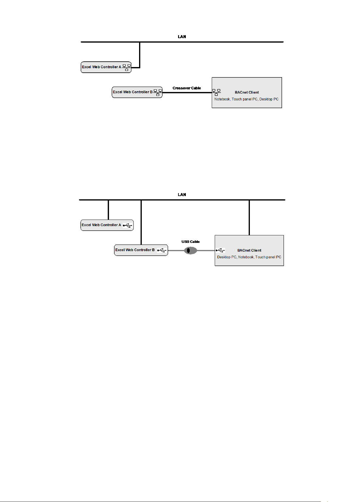
Access Modes to Excel Web Controller Any Excel Web controller on the network can be accessed via the browser-based
The controller can be accessed in one of the following ways:
EN2B0615-GE51).
Excel Web HTML Interface, both locally and remotely. The Excel Web HTML
Interface can reside on any PC platform client such as:
• Desktop PC
• Notebook, Laptop
• Touch panel PC
• LAN (remote access)
Fig. 1. Access to Excel Web controller via LAN
Permanent IP address, allocated by I.T. department
The Excel Web controller can be accessed remotely via LAN by allocating a valid
and permanent IP address to the controller, which is reachable within the LAN.
Procedure:
See Establish Remote LAN Connection section in CARE User Guide
EN2B0182GE51 / 74-5587. Alias IP address, factory default
For access via Ethernet, the Excel Web has a permanent factory default IP
address 192.168.253.20 and Netw or k Mask 255.255.2 55. 0 . Your PC's IP
address must match the Excel Web controller's default IP address. We
recommend using 192.168.253.21 and Network Mask 255.255.255.0.
When using this default address, you must ensure that you have only one
powered-up Excel Web controller on your Ethernet; otherwise, communication
will fail because all Excel Web controllers have the same permanent default IP
address. Alternatively, you can use an Ethernet cross-over cable between your
PC and the Excel Web controller rather than having your PC and the Excel Web
controller both connected to a LAN. Standard Ethernet Interface of your PC
Change the (factory -set) configuration of the integrated Ethernet card so as to
match the Excel Web IP address and IP subnet.
NOTE:
In order to (subsequently) operate on your standard Ethernet network (again),
you will have to change the configuration back to the previous settings. Dedicated Ethernet Interface of your PC
If the laptop or PC with which you wish to access the Excel Web via Ethernet/IP
is not already equipped with an integrated Ethernet Card, or if you want to leave
the IP settings of the integrated network card unchanged, you can buy and install
(into your laptop or PC) an external Ethernet network card.
• Crossover cable (lo cal ac ces s)
EN2B-0962GE51 R0715 12
Page 17
USER GUIDE FALCON
13
Fig. 2. Access to Excel Web controller via crossover cable
To locally connect to the Excel Web controller via Ethernet, a crossover cable
can be used. Hence it has temporarily no connection to any other network and
the Excel Web controller is not reachable in the network.
The crossover cable connection type has the highest transfer rate (100 Mbit/s),
but when applied, the IP address settings of the client need to be changed.
Procedure:
See Establish Local Ethernet Connection via Crossover Cable section in CARE
User Guide EN2B0182GE51 / 74-5587.
• USB (local access)
Fig. 3. Access to Excel Web controller via USB
To locally connect to the Excel Web controller via USB interface, a D-Link DUB-
E100 USB 2.0 Fast Ethernet adapter can be used.
The USB connection type is recommended for the initial setup of an Excel Web
controller due to a reasonable transfer rate (2 Mbit/s) and because no IP address
changes are necessary after installation. In addition, the LAN connection can be
used in parallel and uninterruptedly.
Permanent IP address, factory default For access via USB, the Excel Web has a permanent factory default IP address
192.168.252.20 and Network Mask 255.255.255.0. Your PC's IP address of the
Belkin USB network adapter must match the Excel Web controller's default IP
address subnet: We recommend using 192.168.252.21.
Procedure:
See Establish Local Connection via USB Cable section in CARE User Guide
EN2B0182GE51 / 74-5587.
IP Address Allocation To establish any of the described connections, IP addresses must be allocated to
the relevant network components such as BACnet client, Excel Web controller(s)
and USB network adapter.
For further information, please refer to "Setup Excel Web Controller" section in
CARE User Guide EN2B0182GE51 / 74-5587.
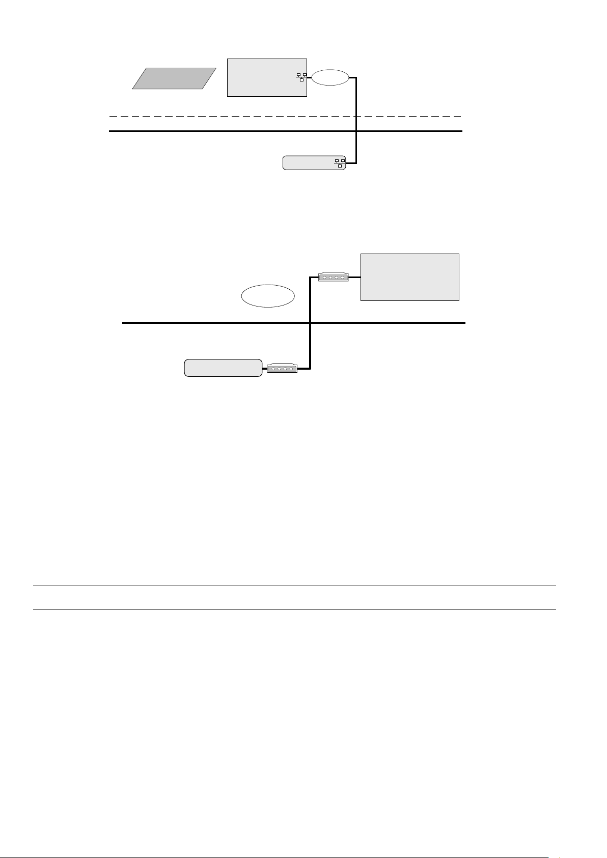
• Internet (remote)
EN2Z-0962GE51 R0715
Page 18
FALCON USER GUIDE
LAN
Excel Web Controller A
Internet
BACnet Client
Desktop PC, Notebook
Provider
Firewall
Telephone network
Modem
Excel Web Controller A
BACnet Client
Desktop PC, Notebook
Modem
Dial-up
Fig. 4. Remote Access to Excel Web controller via Internet
• Web Browser access to Excel Web controller via modem
Without using an Internet provider, dial up access via modem is possible by using
two modems. One must be connected to the telephone network at the Excel Web
controller and one at the BACnet client or PC with Internet Browser.
Fig. 5. Web Browser access to Excel Web controller via modem
• CARE access to Excel Web controller via modem
You can work with CARE on an Excel Web controller via modem by connecting
remotely to the modem attached to the Excel Web controller. When the
connection is established, CARE can connect to the Excel Web controller via IP
address. LON-Commissioning can then be done by using a NIC IP (Loytec)
additionally.
Communication Settings Communication settings in the Excel Web HTML Interface comprise:
• Interface settings such as serial baudrates, IP address, neuron chip ID, MAC
address, automatic logout time of web server
• Modem settings
• Remote central (front-end) settings
Bus-Wide Operation Any user can operate all Excel Web controllers residing on a BACnet network.
Based on its design as an IP device (see also "Communication Protocols"), the
EN2B-0962GE51 R0715 14
Excel Web controller "speaks" BACnet over IP (Internet Protocol) and hence, can be
integrated smoothly and without the need for additional devices into any network
infrastructure having regard to the corresponding network security mechanis m.
Network
Page 19

USER GUIDE FALCON
15
Application layer
Application layer
Presentation layer
Session layer
Transport layer
Transport layer
Network layer
Network layer
Data link layer
Physical layer
Link layer
BACnet *
IP *
Ethernet
BACnet
Functions
Physical
Protocol
Ethernet
OSI Model
TCP / IP Model BACnet over IP*
Fig. 6. Networking model of Excel Web controller
Network Load The network load for one Excel Web controller in combination with one EBI central
is about 1 % network load in a 10 Mbit network.
These figures are based on the following assumptions:
• 20 BACnet properties per display
• BACnet properties are updated by 5 EBI displays simultaneously
• Each property is updated every 5 s. One update message for a simple property
needs 100 bytes, for a complex property 200 bytes.
Calculation: 5 displays * 20 properties/display * 150 bytes/property *
1 update/5 s = 30000 bits per second.
If alarms should be received and properties should be in trend, everything should
not consume more than 100 Kbits/s, which is 0,1 % in a 100 Mbit network.
Communication Protocols BACnet/IP - ISO 16484-5 – ENV 13321-1
Communication with other Excel Web® controllers, with 3
with Honeywell Enterprise Buildings Integrator™ and SymmetrE® front-ends, and
rd
-party BACnet® front-ends is based on the international BACnet® Protocol.
with 3
rd
-party BACnet® devices,
More details on the BACnet® Interoperability can be obtained from the Excel Web®
Protocol Implementation Conformance Statement (PICS).
LonTalk®
Communication with physical I/O modules, with room and zone controllers, and with
Excel 50/500 controllers is based on LonTalk®.
A Free Topology Transceiver (FTT-10A or FT-X1) allows a communication speed of
78 KBaud.
In typical cases, field devices are controlled via Honeywell Distributed I/O
(XFL52xB) or Smart I/O (XFCxxx) modules. Maximum cable lengths are 320 m to
2,200 m.
HTTP
Excel Web® can be operated using a standard Internet Explorer (5.5 or higher) or
Netscape (6.2.1 or higher). The required minimum screen resolution is 800 x 600
pixels. For more details, please refer to the "Operating the Excel Web HTML
Interface" section.
FTP
The firmware and application are downloaded via the standard FTP (File Transfer
Protocol).
Telnet
Telnet access to the Excel Web controller is possible for the purpose of service and
diagnostic of the Linux operating system and the Excel Web firmware. In case this is
needed, please contact your Honeywell representative.
SMTP
EN2Z-0962GE51 R0715
Simple Mail Transfer Protocol is used for the embedded Email alarming functionality
of Excel Web.
Page 20

FALCON USER GUIDE
Time Synchronization BACnet clients such as EBI or 3rd-party BACnet front-ends, can time sync the Excel
EBI Compatibility The Excel Web controller communicates with BACnet front-ends only.
web controller via the standard time sync or UTC time sync BACnet service. When
having multiple Excel web controllers on a network without any BACnet client being
the time master, the time must be set for any controller separately and correctly
before downloading the application.
Supported BACnet front-ends are:
• EBI / SymmetrE Software
For more information, please refer to the following software release bulletins:
− EBI R300.1 with Excel Web / BACnet Software Update
− SymmetrE R300.2 with Excel Web Software Update
− EBI / SymmetrE R310.1 or later
• XFI Software
The XFI has not been tested yet with Excel Web, but supports BACnet
functionality.
Operation and Application Software
Programming The Excel Web® is freely programmable using the CARE Engineering Tool and is
This allows making use of standard, pre-tested and pre-documented application and
Application Control Four selectable control loop speed classes (multitasking) with defined cycle times
User Administration Your control system is protected by defined user access rights. This ensures that
Datapoints Datapoints are the basis of the Excel Web – BACnet system. Datapoints contain
Alarm Handling Alarm handling is defined and realized in the application. BACne t alarming
thus ideal for all Building Control and Building Management tasks.
control strategies.
and switching tables allow tailored and highly effective applications control.
only authorized persons have access to the system data. There are six pre-defined
user levels. The predefined user levels are arranged hierarchically and the
sequence with descending priority is as follows:
• System Admin (128)
• Project Admin (115)
• Building Engineer (96)
• Operator (64)
• Tenant (32)
• Guest (0)
Excel Web® allows the definition of up to 128 user levels by default. The above
mentioned user levels are available. Each user level can have different read and
write rights assigned, e.g. Display Communication Settings, Create and Delete
Calendars, Change clock settings, etc. Several users with individual passwords can
be defined for each user level.
NOTE: There is no limit to the number of users per user level.
system-specific information such as values, status, limit values, and default settings.
The user has easy access to datapoints and the information they contain.
The user can recall and modif y informatio n in the datapoi nt s.
On datapoint level, alarming is done by the BACnet intrinsic reporting service.
The following point changes may generate alarm messages:
• Exceeding limit values (analog points and pulse converter point)
• Changes of state (binary and multi-state input and value datapoints)
• Faults (due to, e.g. LON communication errors or e.g. sensors breaks)
EN2B-0962GE51 R0715 16
Page 21

USER GUIDE FALCON
17
Alarming is further supported by notification class objects, which contain information
required for the distribution and segregation by time and addresses of alarm/event
notifications within a BACnet system.
Notification class objects allow up to 256 alarm priorities. By default, CARE provides
3 notification class objects matching the EBI alarm priorities:
• Urgent
• High
• Low
IMPORTANT
Excel Web does also support the BACnet algorithmic alarming service.
The algorithmic alarming uses the standard BACnet “Event Enrollment Object” and
is used to provide the following functionality:
LON alarming
As LON does not know "devices" but only NVs, I/O module alarming must be
realized by mapping a particular NV to the appropriate "alarm" datapoint in CARE.
Then for the alarm datapoint, the alarm settings are to be defined as usual.
Remote LON Commissioning Excel Web Controllers on a LON bus can be commissioned remotely via LAN / WAN
using CARE or Excelon (can be used as LonWorks protocol analyzer via LAN). Time Programs Time programs comprise schedules and calendars. Schedules
Schedules are daily and weekly time programs. Whenever you want, you can use schedules to enter the setpoint or status for any
datapoint.
Schedules are assigned to plants. Each plant of a controller can have multiple
schedules assigned and each schedule can comma nd datapoints of that plant.
Each schedule specifies a list of datapoint properties to command (switchpoints) on
a weekly basis. The week program defines the normal daily activity of the system by
specifying which switchpoints are to be commanded each day of the week. The
week program applies to a definable time period. There is only one-week program
per schedule.
Schedules offer 16 write priorities that define the priority for writing to the present
value of output and value datapoints. Note that only priorities 9 to 16 are allowed in
the controller.
The write priority applies only to the present value property of virtual points and
output points. The write priority is ignored for all other types of properties.
For every schedule (week program), specific programs called exceptions can be
created. Exceptions have higher priority than the week program and will overwrite
the week program for a definable time period. Exceptions can be one of the
following four time periods:
• Specific Date
e.g. Christmas Eve or 5.5., the whole of May, or the whole year of 2004
• Date Range
e.g. Summer holidays from 29.7-7.9.2004
• Recurring Event
e.g. every last Friday of every month
The internal ring alarm buffer takes max. 100 alarms.
• Warning limits for analog datapoints (Min. and Max. warning limits, in
addition to the Min and Max Alarm limits)
• Alarming for datapoint change between “auto” and “manual”
• Alarming for missing or late acknowledgement of alarms
• Maintenance alarming, based on elapsed runtime of datapoints or number
of state-changes of datapoints.
• Alarming for unsuccessfull transmission of Email alarms
• Alarming for stopped or started plants within Excel Web
EN2Z-0962GE51 R0715
Page 22

FALCON USER GUIDE
• Calendar Reference
A project-wide calendar provides dates, e.g. regional holidays and
public/religious festivals or any other particular date. The time period can be a
specific date, a date range or a recurring event.
Calendars contain exception days or periods, e.g. Christmas, holidays. Calendars
Trending Trending can be performed via the Excel Web HTML Interface residing on any PC
Controller Based Trending A Compact Flash Card (type 1 or type 2) or micro drive allows memory extensions
Protocolling In the context of the Excel Web controller, "protocolling" means creating a log of the
Calendars are valid for the whole project, and are executed in each controller but apply only to
those schedules, which reference calendars. Changes in multiple particular
controller schedules can be quickly made by simply changing a calendar in one
controller. Thus project-wide s ched uli ng can be influ enced.
platform and via BACnet clients. Trend data is stored on an 2 MB integrated Flash
memory which can hold a maximum of 64,000 trend records distributed among 125
trend log objects. In addition, three trend log objects are used for LON statistic
trending. A single trend log object can include max. 2.880 trend records (max. trend
buffer size). One trend record equals 30 bytes. Extended trend memory is possible
by using a 3
can be in ´Ringbuffer` mode or in ´Stop When Full` mode. Trend data are
dynamically created in the controller and can be saved in a .CSV file.
Trend data have unlimited lifetime and survive an application download. Trend
objects must be explicitly deleted via Excel Web HTML Interface or BACnet. This
deletes also the corresponding trend records. The trended object may be a local or
a reference point in the same controller and the trended property may be integer or
floating point, e.g. point value, point state, alarm limit, time stamp.
Trending via BACnet Client
BACnet clients like EBI will use the BACnet ´read range service` to readout trend
values from the Excel Web controller. Trend recovery for BACnet clients, specifically
EBI and SymmetrE optionally provide an automated recovery mechanism which
allows to "backfill" missing trend data on the BACnet client side with trend values
from the Excel Web controller.
for the purpose of expanding integrated trend memory and increasing historical data
storage. The integrated on-board trend memory allows saving of max. 64.000 trend
values.
values or states of the datapoints, which have been assigned to this particular Excel
Web controller. Using the Excel Web HTML Interface, the user must place the
corresponding datapoints into "trend". If, at some later point in time, i.e. after lengthy
operation, a protocol of the Excel Web controller's history is desired, the
corresponding trend data can be generated, viewed, and downloaded (in CSV
format) via the browser interface. For the storage of larger amounts of trend data
(more than 64,000 trend entries – corresponding to approx. 2 MB), a CF card or
micro drive can be used. The trend data can even be downloaded into a BACnet
client if this client supports this BACnet service.
When connected to the Excel Web controller via Internet Browser, all other Excel
Web controllers of the same project can be operated without the necessity of a new
login.
rd
-party standard Compact Flash card or micro drive. Trend data storage
Backup/Restore
The Excel Web controller supports the BACnet Backup/Restore functionality by the
backup/restore of the application files.
When performing a backup/restore of the appli cat ion fil es, th e fol low ing must be
noted:
EN2B-0962GE51 R0715 18
• Online changes may not be considered circa 1 minute before the backup is
started.
• Do not restore the application if the LON interface of the controller has been
changed via CARE.
Page 23

USER GUIDE FALCON
19
Diagnostics
LON Diagnostics The Excel Web HTML Interface allows trending and display of LON specific
BACnet Diagnostics The Excel Web HTML Interface allows display and analysis of BACnet services
Modem Diagnostics Modem diagnostics is based on open LINUX and the Excel Web offers the standard
parameters, e.g. messages receiv ed and tran smi tted , com m unicat io n error s, etc.
which have been initiated or executed by Excel Web.
Furthermore the Excel Web HTML I/F allows searching for BACnet objects in a
BACnet network.
LINUX modem log functionality .
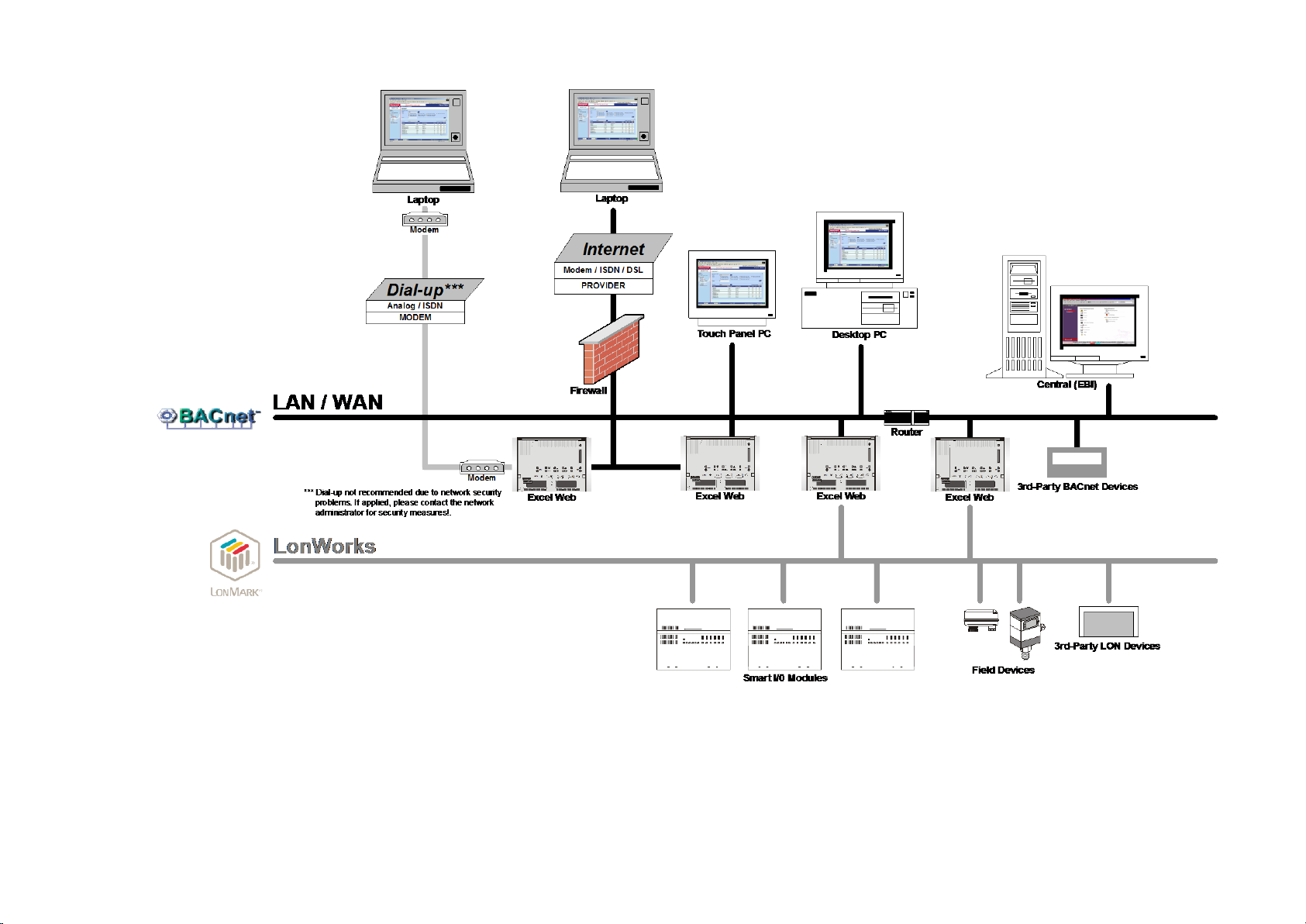
System Architecture Examples
See next pages.
EN2Z-0962GE51 R0715
Page 24
FALCON USER GUIDE
Fig. 7. Open BACnet / LON System Architecture for Plant Control
EN2Z-0962GE51 R0715 20
Page 25
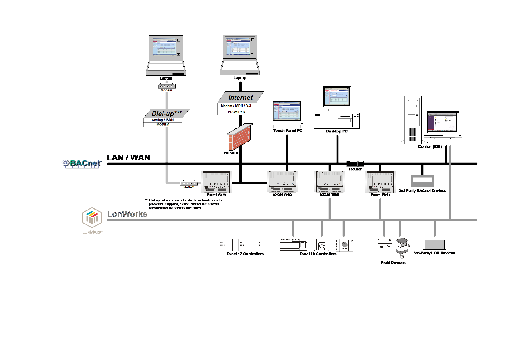
USER GUIDE FALCON
Fig. 8. Open BACnet / LON System Architecture for Room Control
21 EN2Z-0962GE51 R0715
Page 26
USER GUIDE FALCON
EXCEL WEB HTML INTERFACE
The Excel Web® controller is operated via a standard web browser.
By default, an integrated web server provides all operation pages for a full browser-
based operation.
Through the consequent use of software standards, any PC platform can be used as
an operator interface (client). In addition to laptops, desktop PCs or panel PCs can
also be used for direct flush mounting into cabinet doors (IP65).
Other than the operating system and Internet Expl orer® or Netscape®, no software
needs to be installed on the client PCs.
For detailed information on the operation of the Excel Web HTML Interface, please
refer to the "Operating the Excel Web HTML Interface" section, p. 119.
WEB BROWSER ACCESS VIA MODEM
22 EN2Z-0962GE51 R0715
Page 27
USER GUIDE FALCON
Telephone Network
http://192.168.253.20
Excel Web
Controller
IOIO 3
Modem
PC
Notebook, Touch panel PC, Desktop
Modem
COM
Without using an Internet provider, dial up access to the Excel Web controller via
modem is possible by using two modems. One must be connected to the telephone
network at the Excel Web controller and one at the BACnet client or PC with Internet
Browser.
Fig. 9. Web Browser access to Excel Web controller via modem
Setup Modems
Connect the Westermo TDW 33 modem to the port 3 of the Excel web controller and
to the telephone network.
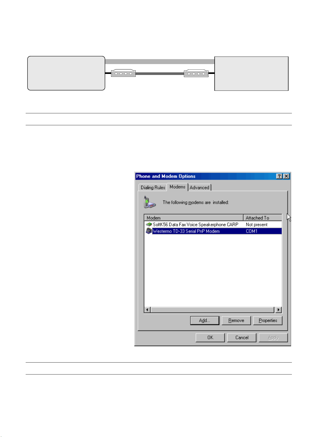
Connect and install a Westermo TDW 33 modem or a comparable model of another
manufacturer according to the relev ant mod em docum entation and the Microsoft
Windows documentation. After successful installation, the modem must be available
in the Phone and Modem Options program group of the Control Panel.
Make Modem Connection
23 EN2Z-0962GE51 R0715
Page 28
FALCON USER GUIDE
NOTE: The following description applies to Windows XP. For Windows 2000, the
screenshots and options are similiar. Please refer to the Windows XP
Online Help for detailed descriptions.
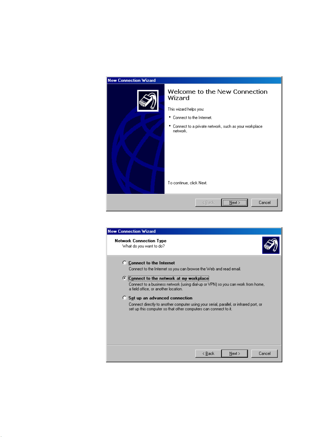
Procedure 1. From the Windows Start menu, select Settings, then Network Connections and
Network Connection Wizard.
RESULT: The New Connection Wizard displays.
2. In the Network Connection Wizard, click the Next button.
3. Select Connect to the network at my workplace, and then click the Next
button.
EN2Z-0962GE51 R0715 24
Page 29
USER GUIDE FALCON
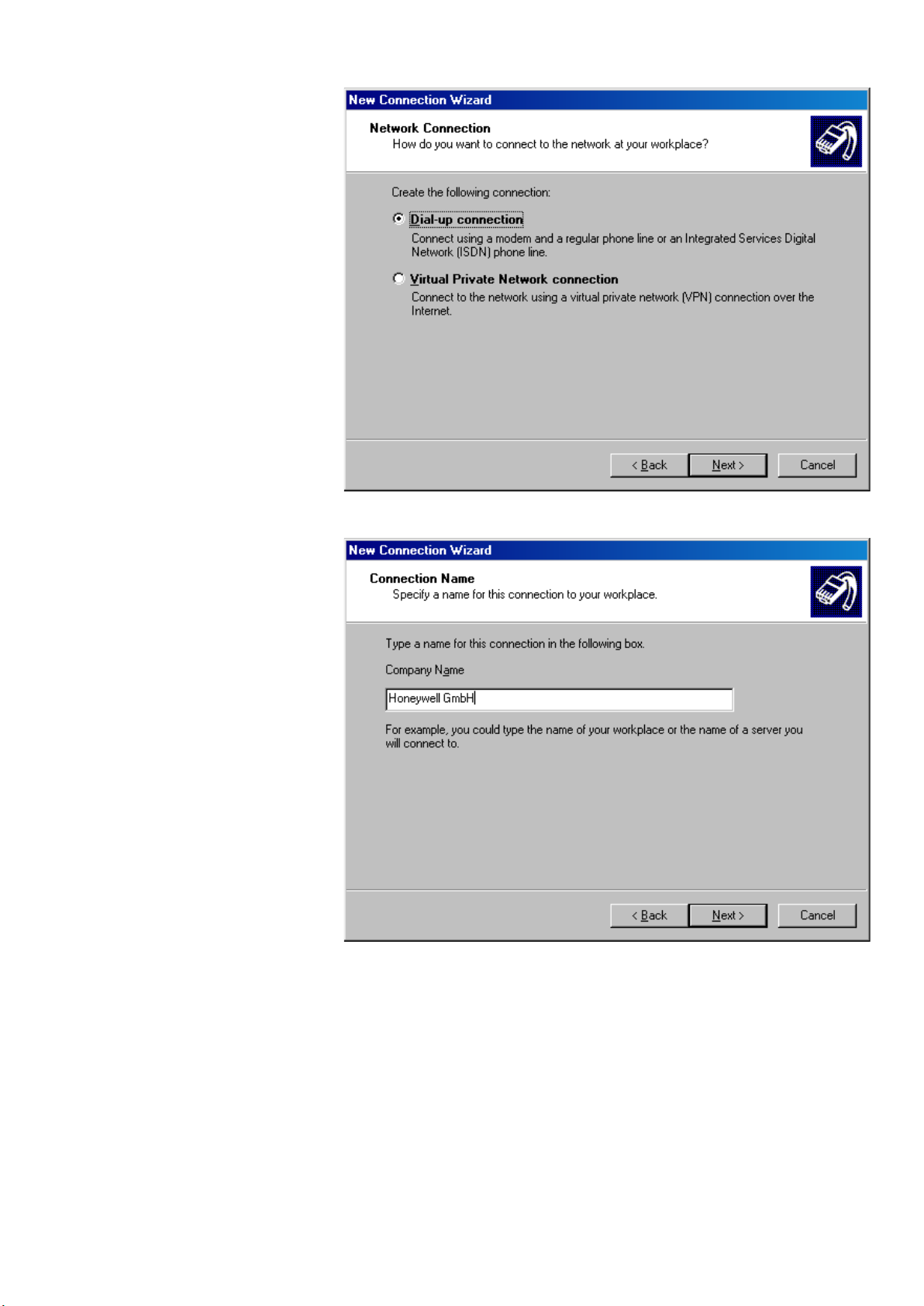
4. Select Dial-up connection, and then click the Next button.
5. In the Company Name field, enter a name for the modem connection, and then
click the Next button.
25 EN2Z-0962GE51 R0715
Page 30
FALCON USER GUIDE
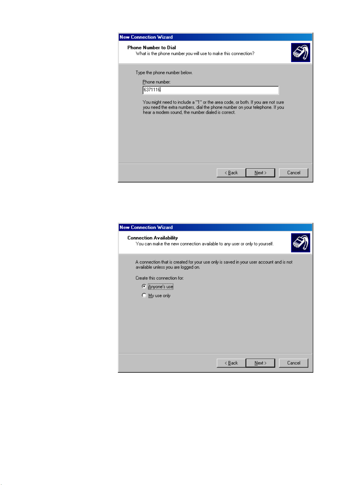
6. In the Phone number field, enter the phone number of the modem connected
to the Excel Web controller, and then click the Next button.
.
NOTE: For the phone number, please contact the telephone network
administrator.
7. Select the connection availability under Anyone´s use or My use only, and
then click the Next button.
.
EN2Z-0962GE51 R0715 26
Page 31

USER GUIDE FALCON
8. Check Add a shortcut to this connection to my desktop, and then click the
Finish button.
9. In the User name field, enter ´xwadmin` and in the Password field, enter the
password.
10. Check Save this user name and password to the following users, and
select Me only or Anyone who uses this computer.
11. Click the Properties button.
27 EN2Z-0962GE51 R0715
Page 32

FALCON USER GUIDE
12. On the General tab, click the Configure button.
13. From the Maximum speed (bps) drop-down list box, select ´115200`, and then
click the OK button.
EN2Z-0962GE51 R0715 28
Page 33

USER GUIDE FALCON
14. Slect the Networking tab.
15. Check and highlight Internet Protocol (TCP/IP) in the list and click the
Properties button.
16. On the General tab, select Obtain an IP address automatically, and then click
the OK button.
29 EN2Z-0962GE51 R0715
Page 34

FALCON USER GUIDE
17. Click the OK button.
RESULT: The Connect… dialog box redisplays.
18. Click the Dial button.
RESULT: You will be connected to the Excel web controller. If successfully
connected, a tooltip in the system tray shows this with a message.
19. To view connection details, hover over the connection icon in the system tray.
RESULT: A tooltip shows connection details such as connec t ion name,
speed, etc.
20. Click on the connection icon.
RESULT: The Status dialog box displays showing more details about the
connection.
EN2Z-0962GE51 R0715 30
Page 35

USER GUIDE FALCON
21. Click Close button.
22. To operate the Excel Web controller via HTML Interface, start your web browser
and enter the following IP address:
http://192.168.253.20
RESULT: The Login screen displays (see next page).
For detailed information on the operation of the Excel Web HTML Interface,
please refer to the "Operating the Excel Web HTML Interface" section, p. 119.
31 EN2Z-0962GE51 R0715
Page 36

FALCON USER GUIDE
Null Modem Cable
http://192.168.253.20
Excel Web
Controller
IOIO 2
PC
Notebook, Touch panel PC, Desktop
COM
WEB BROWSER ACCESS VIA SERIAL INTERFACE (RS 232)
NOTE: This function is not supported by Windows 7.
The Excel Web controller can be connected to the PC via the RS232 interface.
Connect the free COM port of PC to the port 2 of the Excel web controller by using a
null modem cable.
Fig. 10. Web Browser access via serial interface (RS 232)
Procedure 1. From the Windows Start menu, select Settings, then Network and Dial-up
Connections.
RESULT: The Network and Dial-Up Connections window displays.
2. Double-click on Make New Connection.
3. In the Network Connection Wizard, click the Next button.
EN2Z-0962GE51 R0715 32
Page 37

USER GUIDE FALCON
4. Select Connect directly to another computer and click the Next button.
33 EN2Z-0962GE51 R0715
Page 38

FALCON USER GUIDE
5. Select the Guest option.
6. Click the Next button.
7. Select the connection availability under For all users or Only for myself.
8. Click the Next button.
EN2Z-0962GE51 R0715 34
Page 39

USER GUIDE FALCON
9. Enter a name for the connection.
10. In the User name field, enter ´xwadmin` and in the Password field, enter the
password.
11. Click the Properties button.
35 EN2Z-0962GE51 R0715
Page 40

FALCON USER GUIDE
12. Select the Networking tab.
13. Check and highlight Internet Protocol (TCP/IP) in the list and click the
Properties button.
EN2Z-0962GE51 R0715 36
Page 41

USER GUIDE FALCON
14. In the Internet Protocol (TCP/IP) Properties dialog box, selec t Obtain an IP
address automatically and click the OK button.
15. Click the OK button.
RESULT: The Connect… dialog box redisplays.
16. Click the Connect button.
RESULT: You will be connected to the Excel web controller. User name
password, and authentication are verifi ed.
17. If the following message box displays, check the Do not request the failed
protocols next time checkbox and click the Accept button.
18. Check if you have been successfully connected to the Excel Web controller by
clicking on the connection in the Network and Dial-up Connections window.
37 EN2Z-0962GE51 R0715
Page 42

FALCON USER GUIDE
RESULT: If the connection was successfully, the … Status dialog box is
displayed.
If you are not (successfully) connected to the Excel Web controller,
the Connect… dialog box redisplays where you can connect again.
EN2Z-0962GE51 R0715 38
Page 43

USER GUIDE FALCON
19. To operate the Excel Web controller via HTML Interface, start your web browser
and enter the following IP address:
http://192.168.253.20
RESULT: The Login screen displays.
For detailed information on the operation of the Excel Web HTML Interface,
please refer to the "Operating the Excel Web HTML Interface" section, p. 119.
USER ADMINISTRATION
The user administration (user access manager in CARE) is used for defining user
rights according to the required functions. These definitions are done in CARE firstly
by creating the users and issuing the functions they should have permis sio n for in
39 EN2Z-0962GE51 R0715
Page 44

FALCON USER GUIDE
Access Right
User Level
the Excel Web HTML Interface. In addition, the user administration (user access
manager) is used for defining the language and decimal places of values the Excel
Web HTML Interface should display. User rights can be changed in the Excel Web
HTML Interface dependent on the predefinitions of the user in CARE.
Access Rights List An access rights list for a complete project will be created by assigning predefined
User Profile For each user within a project, a user profile with the following properties will be
NOTE: All users can operate all controllers of a project.
Changes in the user administration will be automatically synchronized
among all Excel Web controller s in the same project.
user levels to all executable functions (access rights) of the Excel Web HTML
Interface. An access rights list may look as follows:
Change Communication Settings System Admin
Create and Delete Schedules Building Engineer
Create and Delete Trends Building Engineer
Display Diagnostics Tenant
The predefined user levels are arranged hierarchically and the sequence with
descending priority is as follows:
• System Administrator (128)
• Project Administrator (115)
• Building Engineer (96)
• Operator (64)
• Tenant (32)
• Guest (0)
Example:
When assigning ´Operator` to ´Create & Delete Calendars`, a user having a user
(access) level below ´Operator`, for example ´Tenant` or ´Guest`, is not able to
create and delete calendars. A user having a user level equal to or higher than
´Operator`, for example ´Building Engineer` or ´Project Admin` is able to create and
delete calendars.
NOTE: When creating a project in CARE, the System Admin level is automatically
assigned to the user who has created the project.
Only the user who has System Admin user level can create new
users and edit or delete ex istin g users.
created:
• User name
• User (access) level
• Language
• Decimal places
• Password
• Access rights
• Email address(es)
A user is identified by its user name. One of the predefined user levels will be
appropriately assigned to the user (name).
Due to the access rights list definitions, this assignment automatically determines
the set of access rights, which the user is allowed to execute in the Excel Web
HTML Interface.
All users having a user level higher than or equal to the assigned user level will have
this access right enabled in the Excel Web HTML Interface, all others will not.
NOTE: A user can carry out his/her assigned access rights in all controllers of the
project.
EN2Z-0962GE51 R0715 40
Page 45

USER GUIDE FALCON
ACCESS LEVEL
ACCESS RIGHTS (
FUNCTIONS)
Create and Delete Calendars
Create and Delete Trends
Display Diagnostics
etc
.
USER NAME
SystemAdmin
Building Engineer
Tenant
etc.
John Q
. Public
etc
.
USER PROFILE
LANGUAGE
English (U.S.)
etc
.
DECIMAL
PLACES
2
3
etc.
PASSWORD
**********
Email Address
JohnQ.
Public@yahoo.
com
„second email address
„max
. 5
email addresses“
In addition, the user profile includes the settings of the language in which the Excel
Web HTML Interface is displayed and the number of decimal places of values to be
displayed in the Excel Web HTML Interface.
For the email alarming function, the user must have an email address assigned
which allows receiving alarm emails generated by the Excel Web controller. For
each user, max. 5 email addresses can be assigned .
Finally, a password for each user must be issued for secure operation of the Excel
Web HTML Interface.
Fig. 11. User Profile Creation
Implications of CARE Settings For some items such as datapoints and control loops, access rights can be
predefined in CARE only. Dependent on the settings done in CARE, some items
may not be visible in the Excel Web HTML Interface.
Example: When assigning the read access level ´building engineer` to all analog
inputs, no analog inputs are visible for users having a user access level
assigned which is lower than the ´building engineer` level, e.g. for users
with the user access levels ´operator`, ´tenant`, or ´guest`.
41 EN2Z-0962GE51 R0715
Page 46

FALCON USER GUIDE
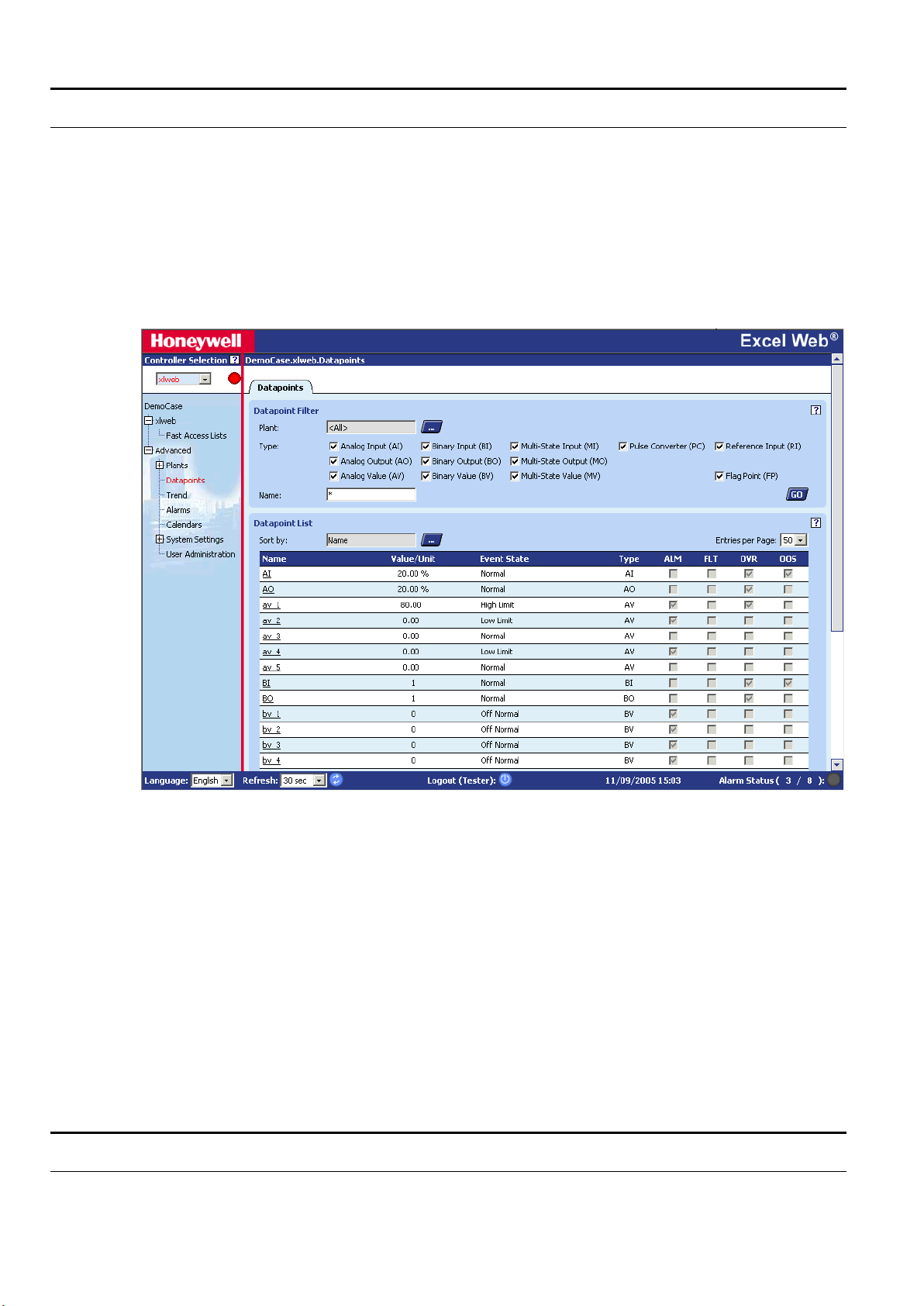
DATAPOINTS
An Excel Web® controller supports up to 600 physical datapoints and an unlimited
number of value datapoints.
A datapoint has different properties according to its type. Properties are displayed
and can be modified via a standard browser on operator interfaces such as laptops,
desktop PCs, or panel PCs. Properties contain information about the given
datapoint. Among many more, this information could be:
• Present value
• Transition events
• Descriptions
• Input limits values
• Operating status
• Elapsed run time
The following sections provide more-detailed information about the different kinds of
datapoints and datapoint properties and explain which properties are assigned to
which datapoints.
In addition, the Excel Web controller has two Integrated I/Os:
Binary Output
• potential-free relay, SPST (single pole single throw), normally open, 24 Vac +/20%, max. 2 A permanent load
• application-driven
• 1 "active" LED, illuminated when contacts closed
The binary output can be used for connecting an alarm buzzer.
Binary Input
• potential-free contact, max. 36 Vdc
• application-driven
• 1 "active" LED, illuminated when contact closed
Physical Datapoints
Physical datapoints are inputs and outputs attached to hardware devices like
sensors and actuators.
The following are examples of physical datapoints:
Analog Inputs NTC, PT 1000, PT 3000, BALCO Sensors (PT 3000/BALCO), standard 0...10 V / 0
Analog Outputs Outputs with a continuous 0...10 V output signal for controlling continuous actuators
Binary Inputs Inputs for processing voltage-free signals (switches, contacts, counters).
Binary Outputs Outputs for driving three-position actuators, for example, a damper motor; two
Multi-State Inputs Inputs used for equipment feedback (Automatic, On, Off)
Multi-State Outputs Outputs controlling multi-stage fans (0, 1, 2, 3)
Pulse Converter Digital inputs for processing pulsed signals up to 20 Hz (depending on I/O module
(4)...20 mA input, to connect outside air temperature sensors, for example.
position devices, for example, a circulation pump; and pulsed outputs
specifications), for example, metered energy consumption.
Value Datapoints
EN2Z-0962GE51 R0715 42
Page 47

USER GUIDE FALCON
Value datapoints are values (interm edia te resul ts and parameters) computed while
the application program is running. In contr ast to phy sical da t apoi nts, value
datapoints are not directly connected to hardware devices.
A typical example of a value datapoint is a room temperature setpoint.
Access via datapoint name During system operation, you may need to access these values. To simplify this
Analog Value Datapoints Analog value points are software points contai ning an analog value in the user
Binary Value Datapoints Binary value points are software points containing a binary value in the user
Multi-state Value Point Multi-state Value datapoints allow switching 32 stages (including the “off stage“) of
A typical example would be a multi-state electric heater or a multi-stage fan.
process, you can include value datapoints in the datapoint list, where you can
access them directly via their datapoint name.
Like physical datapoints, value datapoints, too, can have different properties; for
example, they can specify a manual value, set minimum and maximum values, or
log trends.
The following are types of value datapoints:
• Analog value points
• Binary value points
• Multi-state value points
program.
An analog value point could, for example, contain a flow temperature setpoint cal-
culated from the room setpoint and the outside air temperature via the heating
curve.
program.
For example, logical AND operation:
The AND operation provides a logical 1 output when all input conditions are also
logical 1. Otherwise the output is a logical 0. If the user program contains such an
AND operation on different input conditions, then the output could be available as a
binary value datapoint.
physical digital inputs or outputs. Depending on the number of stages, the multistate value point provides up to 32 editable stage texts, e.g., stage 1, stage 2, stage
3, etc, to be edited in CARE.
Reference Datapoints
If your control and monitoring system contains more than one controller, the controllers communicate with one another via the BACnet bus. This enables one controller both to read and set the datapoints from other controllers, and to read values
rd
-party BACnet devices of the project and external BACnet devices which are
of 3
not in the project.
This data communication is realized via so-called reference input/output points.
They always originate in or write to another plant and may originate in or write to
another controller.
43 EN2Z-0962GE51 R0715
Page 48

FALCON USER GUIDE
BACnet bus
LON
LON
CF
3
2
1
LonWorks
LON
LON
CF
3
2
1
Excel Web Controller Excel Web Controller
Router
Fig. 12. Data exchange via reference datapoints on the BACnet bus
Datapoint Refreshing The following properties will be simultaneously refreshed to an EBI central or the
Please refer also the datapoint property description in the "Reference" section.
The Excel Web controller may have I/O devices connected via the LONWORKS
network. L
ONWORKS network variables (or individual fields of struc tured network
variables) can be mapped to the property "Value" of physical datapoints (AI, BI, AO,
BO, MI, MO). Analog value, binary value, and multi-state value points are also
supported for NV mapping. Note that multi-state points on BACnet start counting
from 1 while enumerated NVs start counting from zero. So a +1 conversion table
must be applied for NVI mapping and a -1 conversion table must be applied for NVO
mapping.
For more information on L
please refer to the CARE User Guide, EN2B-0182GE51.
Each datapoint type has associated with it various parameters, which allow the user
to set, e.g., the datapoint name, the level of access protection, alarm behavior, and
other options. These parameters are called properties. Each property performs a
specific function related to the datapoint.
Not all properties are available for every datapoint type.
Excel Web HTML Interface:
• Present value
• Operating mode
• Reliability
• Status flags
• Event state
Mapped Datapoints
ONWORKS network variables and datapoint mapping,
Datapoint Properties
EN2Z-0962GE51 R0715 44
Page 49

USER GUIDE FALCON
Datapoint Type
Editing
• Event time stamp
• Acknowledged transition
• Command priorities
• Active/Inactive texts
• Elapsed active time
• Time of active time reset
• State texts
• Feedback value
• Time of present value reset
NOTE: A complete list of all properties associated with the various datapoint types
Operating Mode The user is able to switch each datapoint between manual and automatic operation.
Automatic
Under automatic operation, the controller processes the values at the inputs, for
instance from temperature sensors. For outputs, under automatic operation, the
status shown by the user/time switch program is adopted, e.g., ´Heating circuit
pump off`.
Manual
During manual operation, the controller uses the manual values, for example, ´flow
temperature setpoint = 60°C`. Outputs adopt the preselected condition, for example,
´Heating circuit pump on`.
Local Manual Override If manual override controls are present on either the analog out put or digita l out put
modules connected via a L
(automatic/manual override) is displayed in the Excel Web HTML Interface.
can be found in the section Datapoint Properties Overview.
ONWORKS network, then the status of these controls
Properties Descriptions
How to Read the Datapoint Properties Description
In the following, all datapoint properties which exist in the Excel Web HTML
Interface and in CARE are described. Each property description starts with a table
that explains:
• which datapoints the property applies to
• where the property is available, either in CARE or in the HTML Interface or in
both of them
• if the property is editable and where (HTML Interface and/or CARE) it can be
changed.
• the corresponding equivalent name, if the property name is different in the HTML
Interface and in CARE
All valid items are highlighted in gray. Non-valid items remain in white.
Examples: The following table explains the Active / Inactive Text property.
In this case the property applies to the BI, BO and BV datapoint
types. It is available in the HTML Interface and in CARE. It can
be edited in CARE but not in the HTML Interface. In the HTML
Interface the property is not called Active / Inactive Text but is
User Interface HTML Interface CARE
Equivalent Auto, Manual
The following table explains the Ackn. (Acknowledged
displayed as Auto or Manual property.
AI AO AV BI BO BV MI MO MV PC RI RO
- X
Transitions) property. In this case the property applies to all
datapoints except the RI (reference input). It is available in the
45 EN2Z-0962GE51 R0715
Page 50

FALCON USER GUIDE
Datapoint Type
Editing
Datapoint Type
Editing
Datapoint Type
Editing
User Interface
HTML Interface
CARE
Equivalent
Unit
Number of states
State (0)
State (1)
HTML interface only. It cannot be edited at all and there is no
User Interface HTML Interface CARE
Equivalent
In some exceptions, remarks in quotation marks are added. In
User Interface HTML Interface CARE
Equivalent
equivalent.
AI AO AV BI BO BV MI MO MV PC RI RO
the following table of the Engineering Unit property description,
"assigned to value" means that the engineering unit is not
available as property but is assigned to the current value of the
datapoint.
AI AO AV BI BO BV MI MO MV PC RI RO
"assigned to value" X
Ackn. (Acknowledged Transitions)
AI AO AV BI BO BV MI MO MV PC RI RO
User Interface HTML Interface CARE
Equivalent
Shows whether a transition has been acknowledged or not. By default, each
transition will be acknowledged by the Excel Web controller and the Ackn. Property
is checked in the Excel Web HTML Interface. On the EBI central, transitions can be
set to be asked for acknowledgement by the operator manually.
Active / Inactive Text
Datapoint Type AI AO AV BI BO BV MI MO MV PC RI RO
Editing - X
Auto, Manual
To binary points, texts can be assigned in CARE to display the corresponding active
or inactive state of the point in the Excel Web HTML Interface. The texts include
active/inactive (passive) descriptions with unit, and number of states.
Example: Active / Inactive text assigned to binary output for switching a pump.
1 2 OFF ON
2 2 Stopped Running
The actual state is displayed as present value in the Excel Web HTML Interface.
See also "Auto" and "Manual" sections.
EN2Z-0962GE51 R0715 46
Alarm Delay
Page 51

USER GUIDE FALCON
Datapoint Type
Editing
Datapoint Type
Editing
Datapoint Type
User Interface
Equivalent
AI AO AV BI BO BV MI MO MV PC RI RO
User Interface HTML Interface CARE
x X
Equivalent
The alarm delay determines how long a ´To-Off-Normal` or a ´To-Normal` transition
must exist before an alarm is generated. Entering an alarm delay time of 10 seconds
means that the limit value must be exceeded for at least 10 seconds before this
datapoint generates an alarm. If the limit value only lasts for 7 seconds, then no
alarm occurs. The alarm handling for a datapoint can be completely disabled by
setting the alarm delay time to a value of 100000 or higher.
Alarm Text
AI AO AV BI BO BV MI MO MV PC RI RO
User Interface HTML Interface CARE
- X
Equivalent
For the property ´Alarm text`, CARE allows entering personalized alarm texts for the
different event states of an analog or digital point. The assigned alarm text is shown
with the alarm, which is caused by the corresponding transition event.
Alarm texts can have 256 characters at maximum with no restriction on the used
character type.
Analog points have twelve, Digital points have six possible event states. The
following table shows the event states and examples for alarm texts:
Nr. Analog Event States Alarm Text Example Digital Event States Alarm Text Example
1 High Limit to Normal Value below High Limit Fault to Normal Input OK
2 Low Limit to Normal Value above Low Limit Normal to Fault Input Failure
3 Fault to Normal Sensor OK Off-Normal to Nor mal Input back to Normal
4 Normal to High Limit Value above High Limit Normal to Off-Normal Input Change to Alarm
5 Normal to Low Limit Value below Low Limit Fault to Off-Normal
6 Low Limit to High Limit Off-Normal to Fault
7 High Limit to Low Limit
8 Fault to High Limit
9 Fault to Low Limit
10 Normal to Fault Sensor Break
11 High Limit to Fault Sensor Break
12 Low Limit to Fault Sensor Break
47 EN2Z-0962GE51 R0715
Alarm Type
AI AO AV BI BO BV MI MO MV PC RI RO
HTML Interface CARE
Editing - X
Notify Type
According to the BACnet Specification, events can be of the type ´alarm` or ´event`.
On the EBI, alarms will be graphically indicated by blinking in the status line and
shown in the alarm summary. Events will not be indicated in the status line and will
be shown in the event summary.
Page 52

FALCON USER GUIDE
User Interface
Editing
Equivalent
User Interface
Equivalent
Datapoint Type
User Interface
Editing
The notify type can be defined and changed in CARE. In the Excel Web HTML
Interface, the notify type (alarm type) is displayed only.
For all notification classes, notify type ´Alarm` must be used.
See also "Notify Type" section.
Alarm Value
Please refer to the "Alarm Value Enable" section.
Alarm Value Enable
Datapoint Type AI AO AV BI BO BV MI MO MV PC RI RO
HTML Interface CARE
x X
Alarm Value
Defines the alarm condition of a binary input or value point when an alarm should be
reported in case of binary input changes. The alarm condition can be either the
active state or the inactive state of the point e.g. 0 or 1, ON or OFF, Up or Down. If
the present value is equal to this condition for at least the alarm delay time, then an
OFF-Normal event is generated. In addition an alarm delay can be entered.
Auto
Datapoint Type AI AO AV BI BO BV MI MO MV PC RI RO
HTML Interface CARE
Editing x
Sets the datapoint in automatic (Auto) operation mode. In Auto operation mode, the
datapoint shows the present value processed by the controller (sensor input values,
time program output values).
See also "Active / Inactive Text" section.
BACnet Instance
AI AO AV BI BO BV MI MO MV PC RI RO
HTML Interface CARE
-
Equivalent
The BACnet instance number is part of the internal BACnet addressing in every
BACnet system (BACnet communication). The BACnet instance number of
datapoints is not visible in the Excel Web HTML Interface and the user does not
need the BACnet instance number in order to operate the Excel Web controller.
The BACnet instance number of a device object is visible in the Excel Web HTML
Interface.
When creating objects in CARE such as datapoints, schedules or calendars, CARE
assigns an instance number to each object. The instance number is unique within
the same object type but the same instance number may also exist in other object
types. The instance number of the device object is unique on the whole BACnet
network.
EN2Z-0962GE51 R0715 48
Page 53

USER GUIDE FALCON
User Interface
Equivalent
The following table shows examples of instances, which CARE automatically
assigns to the corresponding BACnet objec ts while they are created:
Object Type Instance Number
Analog input 1 1
Analog input 2 2
Analog input 3 3
Analog input 4 4
Analog input 5 5
Binary input 1 1
Binary input 2 2
Binary input 3 3
Binary input 4 4
Binary input 5 5
The instance number in combination with the BACnet object type information is one
method in creating and adding a 3
rd
party BACnet device to the BACnet bus (see
also "BA Cnet Object ID" section).
This information must be provided by or to the project engineer/vendor who is
responsible for the 3
is responsible for integrating the Excel Web controller into a 3
rd
party BACnet device to be added to the CARE project, or who
rd
party BACnet
system.
NOTE: In Europe it is common using the EDE data format for interchanging
information between BACnet objec ts. For fu rther inf o rmat ion , please
access the BACnet Interest Group Europe e.V. at:
http://www.big-eu.org
BACnet Object (Type)
Datapoint Type AI AO AV BI BO BV MI MO MV PC RI RO
HTML Interface CARE
Editing -
The BACnet object type is part of the internal BACnet addressing in every BACnet
system (BACnet communication). The BACnet object type is not visible in the Excel
Web HTML Interface and the user does not need the BACnet object type in order to
operate the Excel Web controller.
In the BACnet standard, BACnet objects are classified in types.
Example: Analog inputs are of BACnet object type "analog input(0)", binary inputs
are of BACnet object type "binary input(3)", devices such as the Excel web
controller and 3
rd
party BACnet devices are of BACnet object type
"device(8)”
The BACnet object type information in combination with the instance number is one
method in creating and adding a 3
rd
party BACnet device to the BACnet bus (see
also "BA Cnet Object ID" section).
This information must be provided by or to the project engineer/vendor who is
responsible for the 3
rd
party BACnet device to be added to the CARE project, or who
is responsible for integrating the Excel Web controller into a 3rd party BACnet
system.
The BACnet Object type defaults according to the BACnet convention are as follows
(see next page):
49 EN2Z-0962GE51 R0715
Page 54

FALCON USER GUIDE
User Interface
Equivalent
Life safety zone
22
Multi-state input
13
Program
16
Trend log
20
BACnet Object Object Type
Anlog input 0
Anlog output 1
Anlog value 2
Averaging 18
Binary input 3
Binary output 4
Binary value 5
Calendar 6
Command 7
Device 8
Event enrollment 9
File 10
Group 11
Life safety point 21
Loop 12
Multi-state ourput 14
Multi-state value 19
Notification class 15
Schedule 17
BACnet Object ID
Datapoint Type AI AO AV BI BO BV MI MO MV PC RI RO
HTML Interface CARE
Editing -
The BACnet object ID is part of the internal BACnet addressing in every BACnet
system (BACnet communication). The BACnet object ID is not visible in the Excel
Web HTML Interface and the user does not need the BACnet object ID in order to
operate the Excel Web controller.
The BACnet object ID is a unique ID within a BACnet device.
BACnet Object IDs must be provided by or to the project engineer/vendor who is
responsible for the 3
is responsible for integrating the Excel Web controller into a 3
rd
party BACnet device to be added to the CARE project, or who
rd
party BACnet
system.
The BACnet object ID will be kept unique within a CARE project and is calculated
within CARE by the following Standard BACnet formula:
BACnet object ID = BACnet object type x 2
22
+ Object Instance number
The typical object addressing within a BACnet system is done by using the device
ID and the Object ID.
EN2Z-0962GE51 R0715 50
Page 55

USER GUIDE FALCON
Datapoint Type
AI
AO
AV
BI
BO
BV
MI
MO
MV
PC
RI
RO
Editing - X
Datapoint Type
Editing
Equivalent
Change of Value Increment
See "Increment" section.
Bit Mask
User Interface HTML Interface CARE
Equivalent Event Parameters
The bitmask shows the values/conditions that are observed.
See also "Bit String(s)" and "Event Enrollment"sections.
Bit String(s)
AI AO AV BI BO BV MI MO MV PC RI RO
User Interface HTML Interface CARE
- X
Equivalent List of Values
Bit String(s) shows the possible logical values (true, false) resulting from the
comparison of the selected values/conditions and the underlying bitstring mask.
See also "Bit Mask" and "Event Enrollment"sections.
Characteristic
Datapoint Type AI AO AV BI BO BV MI MO MV PC RI RO
User Interface HTML Interface CARE
Editing X
If the datapoint should be mapped to a NV (see LON Mapping property) and the
engineering units of both do not match, for example, the NV has °C and the
datapoint has °F, a characteristic (conversion table) must be assigned.
Default characteristics are delivered with the CARE software.
Examples: 2-10 V = 0-100 %
Linear input
Direct out 0-100 %
+1
-1
etc.
For example, the characteristic “Linear input” converts volts (NV value) into percent
(datapoint value) as follows:
NV value DP value
0,000 0,000
10,000 100,00
COV Period
See "Period" section.
51 EN2Z-0962GE51 R0715
Page 56

FALCON USER GUIDE
User Interface
Equivalent
Datapoint Type
Editing
Datapoint Type
Editing
Current Value
Datapoint Type AI AO AV BI BO BV MI MO MV PC RI RO
HTML Interface CARE
Editing "Reset to"
Shows the current accumulated value of the pulse converter. The current value can
be changed by reset.
Datapoint Name
AI AO AV BI BO BV MI MO MV PC RI RO
User Interface HTML Interface CARE
- X
Equivalent
Name assigned to each point for operator use in locating and commanding the
point. This name must be unique within a controller, and this is guaranteed by
CARE.
The temperature of a room is recorded at a sensor input, and then the associated
Example:
datapoint name could be as follows:
Room_Temp.1.10 (Room temperature, 1st floor, room 10)
The datapoint can be accessed directly by selecting this name in the Excel Web
HTML Interface or the EBI.
Point names can have a maximum of 40 alphanumeric characters. They must not
include Tabs, double quotes, space characters and the following characters, ?, *, : ,
/ , \ , < , > . All other printable characters are allowable (A-Z, 0-9, +, -, _,
дцьЯДЦЬйи@§$%&#, etc). For example, 12A is a datapoint name, but 12 is not.
It is not recommended to use quotes or double quotes!
A project may use
network should use the same character set (Honeywell and 3rd party devices).
IMPORTANT
It is recommended not to use characters, which are not part of ANSI X3.4
(US-ASCII). Note that the max. length of the datapoint name for Lon points
should not exceed 13 characters (see Lon point property). But the BACnet
Datapoint name may be longer.
ISO 8859-1 or ANSI X3.4 characters. All BACnet Servers on a
Deadband
AI AO AV BI BO BV MI MO MV PC RI RO
User Interface HTML Interface CARE
x X
Equivalent
Defines the value of the deadband in order to set off an alarm of event type ´ToNormal`. For this, the present value must, for at least the defined alarm delay (time),
remain within the range:
EN2Z-0962GE51 R0715 52
Page 57

USER GUIDE FALCON
User Interface
Equivalent
Low limit plus deadband and high limit minus deadband
Fig. 13. Deadband (1) of analog datapoints
Description
Datapoint Type AI AO AV BI BO BV MI MO MV PC RI RO
HTML Interface CARE
Editing - X
Descriptor
Shows the descriptive Text, which has been entered as Descriptor for the datapoint
in CARE.
A controller contains up to 600 physical datapoints and an unlimited number of value
datapoints. When creating datapoints, an individual datapoint name is assigned to
each of these datapoints.
Plain-language descriptors can be created with an unlimited number of characters
each. These descriptors are then assigned to datapoints via the property
"Descriptor".
Descriptors complete the information concealed behind the datapoint name. They
can contain, for instance, a reference to a section of a building.
The following list is an example of the relationship between datapoint names and
descriptors:
Datapoint Name Descriptor
Room temp floor 1 Heating circuit, West wing
Room temp floor 3 Heating circuit, West wing
Room temp floor 10 Heating circuit, East
Room temp corridor Heating circuit, East
Flow temp floor 1 Heating circuit, West wing
Lights floor 1 Building section V
Lights corridor B uild ing se ctio n V
Descriptor
53 EN2Z-0962GE51 R0715
See "Description" section.
Page 58

FALCON USER GUIDE
User Interface
Equivalent
Datapoint Type
Editing
Equivalent
Datapoint Type
Editing
Datapoint Type
User Interface
Equivalent
Direction
Datapoint Type AI AO AV BI BO BV MI MO MV PC RI RO
HTML Interface CARE
Editing - X
Lon Point
Shows whether a mapped datapoint is mapped to an input NV (NV in) or an output
NV (NV out).
See also "Lon Point" section.
Engineering Unit
AI AO AV BI BO BV MI MO MV PC RI RO
User Interface HTML Interface CARE
"assigned to value" X
Engineering units are pre-defined by the BACnet standard and will be assigned to
datapoints in CARE. In the Excel Web HTML Interface, the present value is
displayed with the assigned engineering unit.
Examples:
If, for instance, the external temperature is measured by an analog datapoint, the
engineering unit of this datapoint must be set to "°C" or "°F". If the electrical load is
detected by a pulse converter input, the engineering unit must be set to "kWh" for
kilowatt-hours.
In the Excel Web HTML Interface, engineering units are displayed read only.
EOV / EOV Optimization
AI AO AV BI BO BV MI MO MV PC RI RO
User Interface HTML Interface CARE
x X
Equivalent
Defines whether the datapoint should be optimized or not, if the datapoint is used as
setpoint for energy optimized heating or ventilation (EOH or EOV).
Event
AI AO AV BI BO BV MI MO MV PC RI RO
HTML Interface CARE
Editing "see Reporting" X
Reporting
Shows the transition types that can be selected for reportin g:
EN2Z-0962GE51 R0715 54
− To Off-Normal
The alarm reaches off-normal state, that is, the datapoint value exceeds
the high limit, or remains under the low limit.
Page 59

USER GUIDE FALCON
User Interface
Equivalent
Datapoint Type
Editing
− Back To-Normal
The alarm is going to normal state, that is, the value of the datapoint
remains under the high limit, or exceeds the low limit.
− To Fault
The alarm originates in a fault such as sensor break, etc. (depends on
point type).
IMPORTANT
In the Excel Web HTML Interface, the transition type is selected by checking the
Reporting checkbox.
See also "Transition Events" and “Alarm and Event Priority Classification” sections.
Always enable both options, ´To Off-Normal` and ´Back To-Normal`,
otherwise you will miss one of the corresponding alar ms.
Event Enrollment
Datapoint Type AI AO AV BI BO BV MI MO MV PC RI RO
HTML Interface CARE
Editing x X
The primary purpose of the Event Enrollment object is to define an event and to
provide a connection between the occurrence of an event and the transmission of a
notification message to one or more recipients. The Event Enrollment object
contains the event-type description, the parameters needed to determine if the event
has occurred (Algorithmic Change Reporting), and a device to be notified.
Alternatively, a Notification Class object may serve to identify the recipients of event
notifications. A device is considered to be "enrolled for event notification" if it is the
recipient to be notified or one of the recipients in a Notification Class object
referenced by the Event Enrollment object. Event Enrollment objects are the basics
for algorithmic change reporting.
See also "Bit Mask" section.
See also "Bit String(s)" section.
See also "Time Delay" section.
Event State
AI AO AV BI BO BV MI MO MV PC RI RO
User Interface HTML Interface CARE
-
Equivalent
For any datapoint type, an application and/or product specific value range is defined
in which the point is in the operating (event) state ´Normal`. If the point value has
changed due to exceptional situations, the ev ent state of a dat apo int can be eith er
´Off-Normal` or ´Fault`.
The event states can be shortly described as follows:
55 EN2Z-0962GE51 R0715
Normal
Point is in normal operating state.
Off-Normal
Point value is out of normal range.
Fault
Point is prevented from proper operation. Point value can be in normal or out of
normal range. Due to the maloperation of the point, the value is unreliable.
Page 60

FALCON USER GUIDE
User Interface
Equivalent
Datapoint Type
Editing
User Interface
Causes for a fault can be, for example sensor and cable breaks. See “Status Flag
indications for details.
High Limit
Point value has exceeded the high limit. Special case of the Off-Normal sta te of
analog inputs, analog outputs, and analog value points (see also Alarm range
properties in the table below).
Low Limit
Point value has dropped below the low limit. Special case of the Off-Nor mal sta te of
analog inputs and outputs (see also Alarm range properties in the table below).
Fault
NOTE: The Fault property exists twice. In one case, it displays the actual status of
Display of actual status
Indicates the fault status of the datapoint. When the ´Fault` status flag is enabled,
the datapoint or the physical input is not reliable, e.g. in case of sensor break (Open
Loop). See “Status Flag Indications” for details.
NOTE: Multiple flag indications may be possible.
Alarm reporting of Faults:
The ´Fault` status of a point will generate an alarm if a notification class is selected.
Example: A ´To-Fault transition` will always enable the ´In Alarm` flag. Hence both,
Definition of fault condition
Defines the state which indicates and sets off a ´Fault` event. If enabled, the fault
text of the corresponding transition event is displayed.
Example:
See also "Is Fault Condition" section.
certain datapoints, in the other case; it allows selecting which condition
should be the fault condition.
Datapoint Type
Editing -
the ´In Alarm` and the ´Fault` status flags are enabled.
User Interface HTML Interface CARE
Equivalent Is Fault Condition
States Fault Fault Text Display
1 NO NO
2 YES YES
AI AO AV BI BO BV MI MO MV PC RI RO
HTML Interface CARE
AI AO AV BI BO BV MI MO MV PC RI RO
x X
High Limit Enable
Datapoint Type AI AO AV BI BO BV MI MO MV PC RI RO
HTML Interface CARE
Editing x x
EN2Z-0962GE51 R0715 56
Page 61

USER GUIDE FALCON
Equivalent
User Interface
Equivalent
Datapoint Type
Editing
The High Limit Enable property defines if high limit alarms are generated on the
BACnet bus. The following conditions must be true for the system to generate an
alarm:
• High limit is exceeded and this condition remains present for at least the defined
alarm delay (time)
• Transition events ´To-OffNormal` and ´To-N orma l`ar e ena ble d
• Notification class (urgent, high or low) is allocated to this point
• Notify type is set to ´Alarm` (not ´Event`)
If all of these conditions are true, then an alarm of event type ´To-Off-Normal` is set
off.
The high limit can be predefined in CARE and changed in the Excel Web HTML
Interface later.
NOTE: According to the BACnet standard, disabling the High Limit does only
With Excel Web it is possible to disable both High and Low Limit alarms at the same
time, if the alarm delay time is set to 100,000 sec or longer.
disable the reporting of the High Limit Alarm onto the BACnet bus. When
the High Limit is exceeded, the datapoint will still be “in Alarm”, and if a
BACnet front-end is polling the alarms of a BACnet controller, also
datapoints with High Limit disabled will be displayed on the BACnet frontend as being “in Alarm”.
In Alarm
NOTE: The In Alarm property exists twice. In one case, it displays the actual status
of certain datapoints, in the other case, it allows selecting which condition
should be the alarm condition.
Display of actual status
Datapoint Type
Editing -
Displays the alarm status of the datapoint, which can be caused by faults and OffNormal conditions.
NOTE: Multiple flag indications may be possible.
Example: A ´To-Fault transition` will always enable the ´In Alarm` flag. Hence both,
the ´In Alarm` and the ´Fault` status flags are enabled.
See also "Fault" and "Out of Service" sections.
Definition of alarm condition
User Interface HTML Interface CARE
Equivalent Is in Alarm
Defines the state which indicates and sets off an ´alarm`. If enabled, the alarm text
of the corresponding transition event is displayed.
Example:
AI AO AV BI BO BV MI MO MV PC RI RO
HTML Interface CARE
AI AO AV BI BO BV MI MO MV PC RI RO
x x
57 EN2Z-0962GE51 R0715
Page 62

FALCON USER GUIDE
States
In Alarm
Alarm Text Display
User Interface
Equivalent
Datapoint Type
Editing
User Interface
Equivalent
1 NO NO
2 YES YES
See also "Is in Alarm" section.
Increment
Datapoint Type AI AO AV BI BO BV MI MO MV PC RI RO
HTML Interface CARE
Editing x x
Change of Value Increment
The change of value increment (COV increment) specifies the minimum change in
present value that causes the controller sending the present value to recipients on
the BACnet bus (e.g. Excel Web HTML Interface, EBI).
The COV increment is also used as the minimum change in the present value for
value-based trending.
NOTE: For the pulse convertor point type, a time-based COV increment is
Usage with Reference Inputs When using reference input points which read input values, the inputs can be reside
either in different plants of the same controller (internal referencing) or in plants of
different controllers (external referencing).
If the reference input point reads values from an internal referencing plant, the
original datapoint value of the input will be taken.
If the reference input point reads values from an external referencing plant, a copy
of the original datapoint value of the input will be taken. Please note, that in this
case, the COV value must be set to appropriate (low) values in order to minimize
falsification of the transmitted value.
possible.
Initial Value
AI AO AV BI BO BV MI MO MV PC RI RO
User Interface HTML Interface CARE
x
Equivalent
For reference input points, an initial value can be entered, which will be utilized at
system startup if the reference input has not yet received a value from the
connected point.
Input NV
Datapoint Type AI AO AV BI BO BV MI MO MV PC RI RO
HTML Interface CARE
Editing - x
NV Type
Defines the network variable type (NVT) of the Lon point in CARE, e.g. SNVT_temp
EN2Z-0962GE51 R0715 58
for an analog input point (NV - Input).
See also "NV Type" section.
Page 63

USER GUIDE FALCON
Datapoint Type
AI
AO
AV
BI
BO
BV
MI
MO
MV
PC
RI
RO
Editing
Datapoint Type
Editing
User Interface
Equivalent
Fault
State Text
Is Fault Condition
Alarm Text Display
2
YES
YES
IO Configuration
User Interface HTML Interface CARE
x
Equivalent
The I/O configuration is not visible in the Excel Web HTML Interface, but only in
CARE.
Analog input and output points must be configured prior to their assignment to a
particular terminal on a module in CARE. This is done by selecting the appropriate
configuration such as NTC, PT100 Type F, etc., for the datapoint. The assignment
of the configuration results in the automatic setting of the configuration properties for
the datapoint.
For pull-up resistor handling, please refer to the "Pull-Up Resistor Handling" section.
Is Alarm Condition
AI AO AV BI BO BV MI MO MV PC RI RO
User Interface HTML Interface CARE
x x
Equivalent In Alarm
Defines the state which enables the ´Alarm` flag. If enabled, the alarm text of the
corresponding transition event is displayed.
Example:
State Text Is Alarm Condition Alarm Text Display
1 NO NO
2 YES YES
See also "In Alarm" section.
Is Fault Condition
Datapoint Type AI AO AV BI BO BV MI MO MV PC RI RO
HTML Interface CARE
Editing x x
59 EN2Z-0962GE51 R0715
Defines the state which enables the ´Fault` flag. If enabled, the fault text of the
corresponding transition event is displayed.
Example:
1 NO NO
See also "Fault" section.
Page 64

FALCON USER GUIDE
User Interface
Equivalent
Datapoint Type
Editing
Equivalent
Datapoint Type
Editing
Last Transition
Datapoint Type AI AO AV BI BO BV MI MO MV PC RI RO
HTML Interface CARE
Editing -
Shows the date when the last transition was performed.
LON Point
AI AO AV BI BO BV MI MO MV PC RI RO
User Interface HTML Interface CARE
- x
Direction
Defines in CARE if the datapoint should be mapped to a NV.
Input points can only be mapped to input NVs and output points can only be
mapped to output NVs.
NOTE: If an output point is defined as "with switches", CARE will automatically
map an input NV to that output point. The input NV will be used for sending
the manual switch state a value from the I/O-board to the Excel Web
controller. The value of the manual switch is reflected at priority 1 in the
priority array of the datapoint.
See also "Direction" section
Low Limit Enable
AI AO AV BI BO BV MI MO MV PC RI RO
User Interface HTML Interface CARE
x x
Equivalent
The Low Limit Enable property defines the low limit for the creation of alarms of
analog points. The following conditions must be true for the system to generate an
alarm:
• The present value falls below the low limit and this condition remains present for
at least the defined alarm delay (time)
• Transition events ´To-OffNormal` and ´To-N orma l`ar e ena ble d
• Notification class (urgent, high or low) is allocated to this point
• Notify type is set to ´Alarm` (not ´Event`)
If all of these conditions are true, then an alarm of event type ´To-Off-Normal` is set
off.
The Low Limit can be predefined in CARE and changed in the Excel Web HTML
Interface later.
NOTE:
According to the BACnet standard, disabling the Low Limit only disables the
reporting of the Low Limit Alarm onto the BACnet bus.
When the Low Limit is exceeded, the datapoint will still be "in Alarm", and if a
BACnet front-end is polling the alarms of a BACnet controller, also datapoints with
Low Limit disabled will be displayed on the BACnet front-end as being “in Alarm”.
EN2Z-0962GE51 R0715 60
Page 65

USER GUIDE FALCON
Datapoint Type
AI
AO
AV
BI
BO
BV
MI
MO
MV
PC
RI
RO
Editing
Datapoint Type
Editing
User Interface
Equivalent
User Interface
Equivalent
With Excel Web it is possible to disable both High and Low Limit alarms at the same
time, if the alarm delay time is set to 100,000 sec or longer.
Manual
User Interface HTML Interface CARE
x
Equivalent
Sets the datapoint in manual operation mode in which the present value will be
overwritten with a desired value manually entered by the user.
See also "Active Text / Inactive Text" section.
Manual Life Safety
AI AO AV BI BO BV MI MO MV PC RI RO
User Interface HTML Interface CARE
x
Equivalent
Shows the status of the manual override switch or potentiometer of the LON
module.
Mapping
Datapoint Type AI AO AV BI BO BV MI MO MV PC RI RO
HTML Interface CARE
Editing -
Shows the mapping type of a mapped datapoint. For example, if the datapoint is
mapped to the present value property, PV = Present Value is displayed.
Notification Class
Datapoint Type AI AO AV BI BO BV MI MO MV PC RI RO
HTML Interface CARE
Editing - x
The notification class can be defined and changed in CARE. In the Excel Web
HTML Interface, only the name of the notification class is displayed.
The notification class enables alarming for the datapoint by selecting a notification
class with a given priority. By default, the following notification classes with
descending priority can be selected:
- Urgent
- High
- Low
61 EN2Z-0962GE51 R0715
Page 66

FALCON USER GUIDE
Datapoint Type
Editing
Datapoint Type
Editing
User Interface
HTML Interface
CARE
Equivalent
User Interface
These default notification classes match the default notification classes of the EBI
central.
Each recipient assigned to a notification class will receive the datapoint alarm
triggered by the selected notification. But, alarms will only be generated for the
enabled transitions (To-Normal, To-OffNormal, and/or To-Fault) of a recipient. Each
enabled transition will be propagated with the selected notification (see also “Alarm
and Event Priority Classification” section).
This connection has not to be mixed up with the transitions selected under
Transition Events (see "Transition Events" section).
Notify Type
AI AO AV BI BO BV MI MO MV PC RI RO
User Interface HTML Interface CARE
- x
Equivalent Alarm Type
The notify type can be defined and changed in CARE. In the Excel Web HTML
Interface, the notify type (alarm type) is displayed only.
For all notification classes, the notify type ´Alarm` must be used.
According to the BACnet Specification, events can be of the type ´alarm` or ´event`.
On the EBI, alarms will be graphically indicated by blinking in the status line and
shown in the alarm summary. Events will not be indicated in the status line and will
be shown in the event summary.
See also "Alarm Type" section.
NV Name
AI AO AV BI BO BV MI MO MV PC RI RO
User Interface HTML Interface CARE
- x
Equivalent
Shows the name of the NV, e.g. NViInsideAirTemp , that is mapped to the
datapoint.
NV Type
Datapoint Type AI AO AV BI BO BV MI MO MV PC RI RO
Editing - x
Input NV, Output NV
Shows the type of the mapped NV, e.g. SNVT_temp.
See also "Input NV" and "Output NV" sections.
Out Of Service
Datapoint Type AI AO AV BI BO BV MI MO MV PC RI RO
HTML Interface CARE
EN2Z-0962GE51 R0715 62
Page 67

USER GUIDE FALCON
Editing
Datapoint Type
Editing
User Interface
x
Equivalent
Generates and indicates the ´out of service` status of the datapoint. The ´out of
service` property allows decoupling the physical input or output from the datapoint.
For inputs the decoupling is done by manual override. For outputs this is done by
checking the ´Out of Service` flag.
The ´out of service` property is suited to fix the physical input or output state, e.g. in
case of maintenance checks.
In the following, the states of the ´out of service` flag/property of the various BACnet
objects are listed:
AI, BI, MI
Out Of Service = unchecked:
Present value has not been overwritten
Out Of Service = checked:
Present value has been overwritten
Present value is decoupled from the physical input and will not track changes to the
physical input.
AO, BO, MO
Out Of Service = checked:
Changes to the present value are decoupled from the physical output.
The present value property is still controlled by the prioritization mechanism (Priority
Array, Relinquish Default)
AV, BV, MV
Out Of Service = checked:
Present value is prevented from being modified by the application.
The present value property is still controlled by the prioritization mechanism (Priority
Array, Relinquish Default)
Pulse Converter
Out Of Service = unchecked:
Present value has not been overwritten
Out Of Service = checked:
Present value has been overwritten
Present value is decoupled from the Count property and will not track changes to
the input.
See also "In Alarm" and "Fault" sections.
Output NV
63 EN2Z-0962GE51 R0715
AI AO AV BI BO BV MI MO MV PC RI RO
User Interface HTML Interface CARE
- x
Equivalent NV Type
Defines the network variable type (NVT) of the Lon point in CARE, e.g.
SNVT_lev_percent for an analog output point (NV - Output).
See also "Input NV" section.
Period
Datapoint Type AI AO AV BI BO BV MI MO MV PC RI RO
HTML Interface CARE
Page 68

FALCON USER GUIDE
Editing
User Interface
Equivalent
Priority Level
Value
1
2
3
4
5
6
7
8
9
10
11
12
13
14
15
x x
Equivalent COV Period
Defines the amount of time in seconds between the periodic transmissions of the
present value. This property can be used alone or in combination with the Increment
property.
When the period property is used in combination with the increment property, the
present value will always be updated periodically independent on the transmissions
of the present value due to the COV setting.
Example:
Increment Period Present Value Update
0,2 K
3 s every 3 s
0,2 K 3 s
when present value has
changed by 0,2 K or more
every 3 s and when present
value has changed by 0,2 K or
more
Priority Level
Datapoint Type AI AO AV BI BO BV MI MO MV PC RI RO
HTML Interface CARE
Editing -
The value of the present value is controlled by a command prior itiz at ion me cha nis m
which is based upon a fixed number of priorities that are assigned to command –
issuing entities (BACnet tasks, control strategy, time program, manual operator
inputs). Each of these entities writes to the present value with its assigned priority
level. The number of priorities is arranged in a priority list of descending priority.
Example (see next page):
Manual Life Safety -
-
-
Critical Equipment Control 19,5 °C
Minimum On Off
Manual Operator 21,0 °C
-
-
-
-
-
Control Program -
EN2Z-0962GE51 R0715 64
Page 69

USER GUIDE FALCON
Priority Level
Value
16
User Interface
Equivalent
Polarity
Present Value
Physical State of Input
Physical State of Device
Datapoint Type
Editing
Datapoint Type
Editing
Relinquish Default 20,0 °C
The priority list can include max. 16 values and will be continuously updated by
written values caused by the command-issuing entities.
The value of the highest priority level is always written to the present value as long
as the priority list is not empty. If the list is empty, the user-definable relinquish
default value is written to the present value.
For the example in the table, Critical Equipment Control has the highest priority and
is written to the present value. As soon as the priorities 5 and 8 are relinquished e.g.
via BACnet service, the relinquish default of 20,0°C will be valid for the present
value.
Polarity
Datapoint Type AI AO AV BI BO BV MI MO MV PC RI RO
HTML Interface CARE
Editing - x
The polarity indicates the relationship between the physical state of the input and
the logical state represented by the present value. If the polarity is NORMAL, then
the ACTIVE state of the present value is also the ACTIVE or ON state of the
physical input. If the polarity is REVERSE, then the ACTIVE state of the present
value is the INACTIVE or OFF state of the physical Input.
NORMAL INACTIVE OFF or INACTIVE not running
NORMAL ACTIVE ON or ACTIVE running
REVERSE INACTIVE ON or ACTIVE not running
REVERSE ACTIVE OFF or INACTIVE running
Property
AI AO AV BI BO BV MI MO MV PC RI RO
User Interface HTML Interface CARE
-
Equivalent
By default, the present value is selected as property of a reference input point in
CARE.
Read Access Level
AI AO AV BI BO BV MI MO MV PC RI RO
User Interface HTML Interface CARE
- x
Equivalent
65 EN2Z-0962GE51 R0715
Page 70

FALCON USER GUIDE
User Interface
Equivalent
BACnet-Bus
Plant A1
Source Point
Plant
A2
Receiver Point
Physical Point or
Value Point
Reference
Input Point
CONTROLLER A
Data
Data
Plant B1
Source Point
Physical Point or
Value Point
CONTROLLER B / 3rd Party DEVICE
NOTE: Controllers / 3rd Pary Devices can be in the sa me or in dif ferent projects.
The read access level can be defined and changed in CARE only. In the Excel Web
HTML Interface, the read access level is displayed only.
The read access level assigned to a datapoint determines which user level can read
values (properties) of that particular datapoint on the Excel Web HTML Interface.
A user who has a user level equal to or higher than the assigned read access level
of the datapoint, will have this access right enabled in the Excel Web HTML
Interface, all others will not (for further details, please refer to the User
Administration section).
Reference
Datapoint Type AI AO AV BI BO BV MI MO MV PC RI RO
HTML Interface CARE
Editing x
The reference property of a reference input point provides the source (BACnet
object) which passes the value to the reference input point. The reference property
of a reference output point provides the source (BACnet object) which passes the
value to the reference output point.
Sources can be any point of any Excel Web controller and 3
of the project.
Reference Points Reference points are a type of software point that can share point information
across plants. If plants are located in different controllers, the point information will
be automatically transferred across the BACnet bus.
Reference Input Points Reference input points receive information from a point in another plant of the same
controller (internal reference) or of another plant in another controller or 3
device (external reference). Controllers and 3
rd
- party devices can reside in the
same or in different projects (for detailed procedure see CARE User Guide EN2B0182GE51).
Each reference input is associated with a physical or value datapoint (source point)
somewhere in a plant residing in a controller on the bus. The source point cannot be
a receiver point and source point and receiver point cannot reside in the same plant.
rd
-party BACnet device
rd
- party
Fig. 14. Data exchange between plants via reference input points
EN2Z-0962GE51 R0715 66
Page 71

USER GUIDE FALCON
User Interface
Equivalent
No Error Detected
Loop is in proper condition, that is, present value is
reliable; that is, no other fault has been detected.
No Sensor
Sensor may be not connected
No Output
Hardware may be not connected
Unreliable Other
The controller has detected that the present value is
Input is not cycling as expected.
Datapoint Type
User Interface
Equivalent
Datapoint Type
Editing
Reference Input Point Operation If the reference input point reads values from an internal referencing plant, the
original datapoint value of the input will be taken.
If the reference input point reads values from an external referencing plant, a copy
of the original datapoint value of the input will be taken. Please note, that in this
case, the “Change of Value” (COV) value of the source point must be set to
appropriate (low) values in order to minimize falsification of the transmitted value.
Reliability
Datapoint Type AI AO AV BI BO BV MI MO MV PC RI RO
HTML Interface
Editing -
Shows whether the hardware assigned to the data poi nt is in proper con dit ion or not .
Depending on the datapoint type, the following conditions may be displayed:
unreliable, but none of the other conditions describe
the nature of the problem. A generic fault other than
those listed above has been detected, e.g., a Binary
NOTE: For binary output datapoints, the reliability will work only if the service type
of the corresponding NVo in CARE is set to ´acknowledged`.
Relinquish Default
AI AO AV BI BO BV MI MO MV PC RI RO
HTML Interface CARE
Editing x x
Defines the value that will be written to the present value, if the priority list is empty
which means that no other value is present in the priority list. The relinquish default
value allows starting up a control system with a defined status/value.
The relinquish default value is predefined in the application in CARE and can be
changed in the Excel Web HTML Interface.
For further information on priority levels and command priorities, please refer to the
"Priority Level" section.
Relinquish Priority
67 EN2Z-0962GE51 R0715
AI AO AV BI BO BV MI MO MV PC RI RO
User Interface HTML Interface CARE
x x
Page 72

FALCON USER GUIDE
Equivalent
Datapoint Type
AI
AO
AV
BI
BO
BV
MI
MO
MV
PC
RI
RO
Editing
Datapoint Type
Editing
User Interface
HTML Interface
CARE
Equivalent
User Interface
Equivalent
Defines the value that will be written to the present value, if the priority list is empty
which means that no other value is present in the priority list. The relinquish default
value allows starting up a control system with a defined status/value. The relinquish
default value is predefined in the application in CARE and can be changed in the
Excel Web HTML Interface.
For further information on priority levels and command priorities, please refer to the
"Priority Level" section.
Reporting
User Interface HTML Interface CARE
x x
Equivalent Transition Events
Defines, which transition type will be reported, that is, which transition should be
saved in the alarm buffer and in the alarm list in the HTML Interface.
See also "Transition Events" section.
Reset to
AI AO AV BI BO BV MI MO MV PC RI RO
User Interface HTML Interface CARE
x
Equivalent
Resets the current value of the pulse converter or the runtime counter of a binary
output to a specific value. The counting will restart.
See also "Current Value" section.
Runtime (Active Time)
Datapoint Type AI AO AV BI BO BV MI MO MV PC RI RO
Editing "Reset to"
Shows the runtime of the connected device. The runtime (active time) can be
changed by reset.
The runtime can be reported as follows:
In CARE, use the IDT statement to read the ´Elapsed Active Time` property of a
datapoint. Compare this value to a limit value and use an additional point to report
an alarm.
Scaling Factor
EN2Z-0962GE51 R0715 68
Datapoint Type AI AO AV BI BO BV MI MO MV PC RI RO
HTML Interface CARE
Editing x
Page 73

USER GUIDE FALCON
User Interface
Equivalent
User Interface
Equivalent
Datapoint Type
Editing
Input pulses from utility meters (gas, water, heat, etc.) transmitted via LonWorks can
be connected to pulse converter inputs using the property "Scaling Factor". The
pulses supplied by the meters are multiplied by the scaling factor and are then ready
to be read as pure consumption values. The "Scaling Factor" thus always indicates
the value of each pulse received.
The adjustable range is 0.0 through 100,000, 000. 0,
The number of decimal places depends on the selected engineering unit.
Example: A heat meter supplies 10 pulses per kWh "consumed". Accordingly, the
scaling factor (= value of a pulse) is 0.1 kWh/pulse.
State Text
Datapoint Type AI AO AV BI BO BV MI MO MV PC RI RO
HTML Interface CARE
Editing - x
State Texts
Multistate datapoints allow switching 256 states (stages) including the “off sta ge" of
physical digital inputs or outputs. For each state, a state text can be created and
assigned to the point in CARE. The state text is displayed on the Excel Web HTML
Interface when the point switches the input or output to the corresponding state
(stage).
Example: Multi-stage fan with state texts: stage 1, stage 2, stage 3, etc.
States
See "#States and State Text" sections.
#States
Datapoint Type AI AO AV BI BO BV MI MO MV PC RI RO
HTML Interface CARE
Editing - x
States
Shows the number of states of a multi-state datapoint.
Time Delay
AI AO AV BI BO BV MI MO MV PC RI RO
User Interface HTML Interface CARE
x x
Equivalent Alarm Delay
The time delay determines how long a ´To-Off-Normal` or a ´Back-To-Normal`
transition must exist before an event enroll ment alar m is sent to the rec ipi ent.
Entering a time delay of 10 seconds means that the limit value must be exceeded
for at least 10 seconds before this event enrollment sends an event notification to
the recipient. If the limit value only lasts for 7 seconds, then no event notification is
sent.
69 EN2Z-0962GE51 R0715
Page 74

FALCON USER GUIDE
User Interface
Equivalent
Datapoint Type
Editing
Datapoint Type
Editing
Datapoint Type
User Interface
Equivalent
User Interface
Equivalent
Time of Last Reset
Datapoint Type AI AO AV BI BO BV MI MO MV PC RI RO
HTML Interface CARE
Editing -
Shows the time of the last reset of a binary output or pulse converter datapoint.
Transition Events
AI AO AV BI BO BV MI MO MV PC RI RO
User Interface HTML Interface CARE
"see Reporting" x
Equivalent Event
Defines which transition type (To-Off-Normal, Back To-Normal, and/or To Fault) will
be reported and tracked by time stamping. The timestamps can be seen in the Excel
Web HTML Interface .
See also "Event" and "Reporting" sections.
Type
AI AO AV BI BO BV MI MO MV PC RI RO
User Interface HTML Interface CARE
-
Equivalent
Shows the datapoint type, e.g. analog input, digital output, etc.
With Switches / 3 Position Output
AI AO AV BI BO BV MI MO MV PC RI RO
HTML Interface CARE
Editing x
The With Switches / 3 Position Output options are not visible in the Excel Web
HTML Interface, but only in CARE.
Defines whether the point transmites a continuous signal and is on a board with
switches (AO, BO), or if the point is a 3 position output (AO).
Write Access Level
Datapoint Type AI AO AV BI BO BV MI MO MV PC RI RO
HTML Interface CARE
Editing - x
The write access level can be defined and changed in CARE only. In the Excel Web
HTML Interface, the write access level is displayed only.
The write access level assigned to a datapoint determines which user level can write
values (properties) to that particular datapoint on the Excel Web HTML Interface.
EN2Z-0962GE51 R0715 70
Page 75

USER GUIDE FALCON
"Datapoint name displayed
in title line of dialog"
Datapoint Name
-
+
GENERAL
Type “datapoint type”
“n.a.” - -
Mapping
“n.a.” - -
NV Name
"automatically
CARE"
-
-
NV type
Input NV - +
NV type
Output NV - +
Direction
Lon Point - +
Read access level
Read access level
-
+
Write access level
Write access level
-
+
ALARMING
Notification class
Notification class
notification-class
- + +
Notify type
Notify type
notify-type
- + +
Event:
under Reporting, see
Reporting:
Normal
+
+
A user who has a user level equal to or higher than the assigned write access level
of the datapoint, will have this access right enabled in the Excel Web HTML
Interface, all others will not (for further details, please refer to the User
Administration section).
Datapoint Properties Overview
Each point in a controller has associated properties such as datapoint name,
notification class and descriptor. Point properties may not be available for editing in
BACnet front-ends such as the EBI central, or in the Excel Web HTML Interface.
Contrariwise in CAREm, some online properties such as present value, statuses,
etc. are not available in principle.
This chapter contains tables for each point type. The tables list point properties and
presents the following information for each:
• Pro perty denotation specifies either the attribute name in the related CARE
Datapoint Properties tab and/or in the Excel Web Datapoint Details tabs.
• Whether or not the property is available for off-line editing. “Off-line” editing
refers to changes made to database values while the controller is not active in
the system. In other words, when you are using CARE to change copies of
controller files, not the files in the actual controller.
• Whether or not the attribute is available for on-line editing. “On-line” editing
refers to changes made to controller files while the controller is active. For
example, if you are using the Excel Web HTML Interface or a BACnet client to
change field values in a controller while it is operating.
Analog Input
Property Denotation Online-Editing Offline-Editing
Excel Web HTML
Interface
Description Descriptor description - + +
To Off-Normal, To Fault,
Back to Normal “selectable
CARE BACnet
generated by
To Off-Normal, To
Fault, Back to
Excel Web
HTML Interface
BACnet CARE
71 EN2Z-0962GE51 R0715
Page 76

FALCON USER GUIDE
Property Denotation
Online-Editing
Offline-Editing
Interface
HTML Interface
Reporting”
Reporting
Reporting
event-enable
+ + +
Ackn(owledged)
“n.a.” - -
Last transition
“n.a.” - -
High limit enable
High limit Reporting
high-enable
+ + +
Low limit enable
Low limit Reporting
low-enable
+ + +
Deadband
Deadband
deadband
+ + +
Alarm delay
Alarm delay
time-delay
+ + +
VALUES
Auto, Manual
“n.a.” + -
Minimum Present Value
Min Present Value
min-pres-value
- + +
Maximum Present Value
Max Present Value
max-pres-value
- + +
In alarm
“n.a.” - -
Fault
“n.a.” - -
Overridden
“n.a.” - -
Out of Service
“n.a.” - -
Increment
Change of value
increment
cov-increment
+ + +
Alarm text, “displayed in
alarm buffer"
Alarm text - +
"assigned to value"
Engineering unit
-
+
“n.a.”
IO Configuration
-
+
“n.a.”
Characteristic
-
+
“n.a.”
Point role (EDK)
-
+
“n.a.”
BACnet Object
Type
-
-
“n.a.”
BACnet Object ID
-
-
“n.a.”
BACnet Object
Instance
-
-
EVENT ENROLLMENTS
EVENT
ENROLLMENTS
+
+
Name
Name - +
Description
Description - +
Event type
Event type - -
High Limit
High Warning Limit
+
+
Low Limit
Low Warning Limit
+
+
Deadband
Deadband + +
Bit Mask, Bit String(s)
Status Flags
-
+
Bit Mask, Bit String(s)
Event Parameters
-
+
Bit String(s)
List of Values
-
-
Time delay
Alarm delay + +
Notify type
Notify type - +
Notification class
Notification class
-
+
Event:
Reporting”
Reporting:
+
+
Reporting
Reporting + +
Ackn(owledged)
“n.a.” + -
Last transition
“n.a.” - -
“n.a.”
BACnet object ID
-
-
Event state
“n.a.” - -
Object type
“n.a.” - -
Read access level
Read access level
-
+
Write access level
Write access level
-
+
Excel Web HTML
CARE BACnet
Excel Web
BACnet CARE
To Off-Normal, To Fault,
Back to Normal “selectable
under Reporting, see
NOTE: Comments are written in Italic and in “quotation marks”
EN2Z-0962GE51 R0715 72
To Off-Normal, To
Fault, Back to
Normal
Page 77

USER GUIDE FALCON
73 EN2Z-0962GE51 R0715
Page 78

FALCON USER GUIDE
Interface
HTML Interface
"Datapoint name displayed
in title line of dialog"
Datapoint Name
-
+
Type “datapoint type”
“n.a.” - -
Mapping
“n.a.” - -
NV Name
"automatically
CARE"
-
-
NV type
Input NV - +
NV type
Output NV - +
Direction
Lon Point - +
Read access level
Read access level
-
+
Write access level
Write access level
-
+
ALARMING
Notification class
Notification class
-
+
Notify type
Notify type
notification-class
- + +
Event:
Reporting”
Reporting:
notify-type
+ + +
Reporting
Reporting + +
Ackn(owledged)
“n.a.”
event-enable
- + -
Last transition
“n.a.” - -
High limit enable
High limit Reporting
+
+
Low limit enable
Low limit Reporting
high-enable
+ + +
Deadband
Deadband
low-enable
+ + +
Alarm delay
Alarm delay
deadband
+ + +
time-delay
+
VALUES
Auto, Manual
“n.a.” + -
Minimum Present Value
Min Present Value
-
+
Maximum Present Value
Max Present Value
min-pres-value
- + +
Manual Life Safety
“n.a.”
max-pres-value
- + -
In alarm
“n.a.” - -
Fault
“n.a.” - -
Overridden
“n.a.” - -
Out of Service
“n.a.” - -
Increment
Change of value
increment
cov-increment
+ + +
COMMAND PRIORITIES
Relinquish default
Relinquish default
relinquish-default
+ + +
Alarm text, “displayed in
alarm buffer"
Alarm text - +
"assigned to value"
Engineering unit
-
+
“n.a.”
IO Configuration
-
+
“n.a.”
Characteristic
-
+
“n.a.”
Point role (EDK)
-
+
“n.a.”
With Switches
-
+
“n.a.”
3 Position Output
-
+
“n.a.”
BACnet Object
-
-
Analog Output
Property Denotation
Excel Web HTML
GENERAL
Description Descriptor description - + +
CARE BACnet
generated by
Online-Editing
Excel Web
BACnet CARE
Offine-Editing
To Off-Normal, To Fault,
Back to Normal “selectable
under Reporting, see
To Off-Normal, To
Fault, Back to
Normal
EN2Z-0962GE51 R0715 74
Page 79

USER GUIDE FALCON
Property Denotation
Interface
HTML Interface
Type
“n.a.”
BACnet Object ID
-
-
“n.a.”
BACnet Object
Instance
-
-
EVENT ENROLLMENTS
EVENT
ENROLLMENTS
+
+
Name
Name - +
Description
Description - +
Event type
Event type - -
High Limit
High Warning Limit
+
+
Low Limit
Low Warning Limit
+
+
Deadband
Deadband + +
Bit Mask, Bit String(s)
Status Flags
-
+
Bit Mask, Bit String(s)
Event Parameters
-
+
Bit String(s)
List of Values
-
-
Time delay
Alarm delay + +
Notify type
Notify type - +
Notification class
Notification class
-
+
Event:
Reporting”
Reporting:
+
+
Reporting
Reporting + +
Ackn(owledged)
“n.a.” + -
Last transition
“n.a.” - -
“n.a.”
BACnet object ID
-
-
Event state
“n.a.” - -
Object type
“n.a.” - -
Read access level
Read access level
-
+
Write access level
Write access level
-
+
Excel Web HTML
To Off-Normal, To Fault,
Back to Normal “selectable
under Reporting, see
CARE BACnet
To Off-Normal, To
Fault, Back to
Normal
Online-Editing
Excel Web
BACnet CARE
Offine-Editing
NOTE: Comments are written in Italic and in “quotation marks”
75 EN2Z-0962GE51 R0715
Page 80

FALCON USER GUIDE
Interface
HTML Interface
"Datapoint name displayed
in title line of dialog"
Datapoint Name
-
+
Type “datapoint type”
“n.a.” - -
Mapping
“n.a.” - -
NV Name
"automatically
CARE"
-
-
NV type
Input NV - +
NV type
Output NV - +
Direction
Lon Point - +
Read access level
Read access level
-
+
Write access level
Write access level
-
+
ALARMING
Notification class
Notification class
notification-class
- + +
Notify type
Notify type
notify-type
- + +
Event:
Reporting”
Reporting:
+
+
Reporting
Reporting
event-enable
+ + +
Ackn(owledged)
“n.a.” - -
Last transition
“n.a.” - -
High limit enable
High limit Reporting
high-enable
+ + +
Low limit enable
Low limit Reporting
low-enable
+ + +
Deadband
Deadband
deadband
+ + +
Alarm delay
Alarm delay
time-delay
+ + +
VALUES
Auto, Manual
“n.a.” + -
Manual Life Safety
“n.a.” - -
EOH/EOV Optimization
EOH/EOV
Optimization
+
+
In alarm
“n.a.” - -
Fault
“n.a.” - -
Overridden
“n.a.” - -
Out of Service
“n.a.” - -
Increment
Change of value
increment
cov-increment
+ + +
COMMAND PRIORITIES
Relinquish default
Relinquish default
relinquish-default
+ + +
Alarm text, “displayed in
alarm buffer"
Alarm text - +
"assigned to value"
Engineering unit
-
+
“n.a.”
Point role (EDK)
-
+
“n.a.”
BACnet Object
Type
-
-
“n.a.”
BACnet Object ID
-
-
“n.a.”
BACnet Object
Instance
-
-
Analog Value
Property Denotation
Excel Web HTML
GENERAL
Description Descriptor description - + +
CARE BACnet
generated by
Online-Editing
Excel Web
BACnet CARE
Offline-Editing
To Off-Normal, To Fault,
Back to Normal “selectable
under Reporting, see
To Off-Normal, To
Fault, Back to
Normal
EN2Z-0962GE51 R0715 76
Page 81

USER GUIDE FALCON
Property Denotation
Interface
HTML Interface
EVENT ENROLLMENTS
EVENT
ENROLLMENTS
+
+
Name
Name - +
Description
Description - +
Event type
Event type - -
High Limit
High Warning Limit
+
+
Low Limit
Low Warning Limit
+
+
Deadband
Deadband + +
Bit Mask, Bit String(s)
Status Flags
-
+
Bit Mask, Bit String(s)
Event Parameters
-
+
Bit String(s)
List of Values
-
-
Time delay
Alarm delay + +
Notify type
Notify type - +
Notification class
Notification class
-
+
Event:
Reporting”
Reporting:
+
+
Reporting
Reporting + +
Ackn(owledged)
“n.a.” + -
Last transition
“n.a.” - -
“n.a.”
BACnet object ID
-
-
Event state
“n.a.” - -
Object type
“n.a.” - -
Read access level
Read access level
-
+
Write access level
Write access level
-
+
Excel Web HTML
To Off-Normal, To Fault,
Back to Normal “selectable
under Reporting, see
CARE BACnet
To Off-Normal, To
Fault, Back to
Normal
Online-Editing
Excel Web
BACnet CARE
Offline-Editing
NOTE: Comments are written in Italic and in “quotation marks”
77 EN2Z-0962GE51 R0715
Page 82

FALCON USER GUIDE
Interface
HTML Interface
"Datapoint name displayed
in title line of dialog"
Datapoint Name
-
+
Type “datapoint type”
“n.a.” - -
Mapping
“n.a.” - -
NV Name
"automatically
CARE"
-
-
NV type
Input NV - +
NV type
Output NV - +
Direction
Lon Point - +
Read access level
Read access level
-
+
Write access level
Write access level
-
+
ALARMING
Notification class
Notification class
notification-class
- + +
Notify type
Notify type
notify-type
- + +
Event:
Reporting”
Reporting:
+
+
Reporting
Reporting
event-enable
+ + +
Ackn(owledged)
“n.a.” - -
Last transition
“n.a.” - -
Alarm value enable
Alarm value
alarm-value
+ + +
Alarm delay
Alarm delay
time-delay
+ + +
VALUES
Auto, Manual
Active / Inactive Text
“n.a.” + -
Polarity
Polarity - +
In alarm
“n.a.” - -
Fault
“n.a.” - -
Overridden
“n.a.” - -
Out of Service
“n.a.” - -
“n.a.”
Runtime (active
Time of last reset
-
-
Alarm text, “displayed in
alarm buffer"
Alarm text - +
"assigned to value"
Engineering unit
-
+
“n.a.”
Point role (EDK)
-
+
“n.a.”
BACnet Object
Type
-
-
“n.a.”
BACnet Object ID
-
-
“n.a.”
BACnet Object
Instance
-
-
EVENT ENROLLMENTS
EVENT
ENROLLMENTS
+
+
Name
Name - +
Description
Description - +
Event type
Event type - -
Binary Input
Property Denotation
Excel Web HTML
GENERAL
Description Descriptor description - + +
CARE BACnet
generated by
Online-Editing
Excel Web
BACnet CARE
Offline-Editing
To Off-Normal, To Fault,
Back to Normal “selectable
under Reporting, see
“n.a.”
“n.a.”
To Off-Normal, To
Fault, Back to
Normal
time)
Reset to
+
-
-
-
EN2Z-0962GE51 R0715 78
Page 83

USER GUIDE FALCON
Property Denotation
Interface
HTML Interface
High Limit
High Warning Limit
x
x
Low Limit
Low Warning Limit
x
x
Bit Mask, Bit String(s)
Status Flags
-
x
Bit Mask, Bit String(s)
Event Parameters
-
x
Bit String(s)
List of Values
-
-
Time delay
Alarm delay x x
Notify type
Notify type - x
Notification class
Notification class
-
x
Event:
Reporting”
Reporting:
+
+
Reporting
Reporting + +
Ackn(owledged)
“n.a.” + -
Last transition
“n.a.” - -
“n.a.”
BACnet object ID
-
-
Event state
“n.a.” - -
Object type
“n.a.” - -
Read access level
Read access level
-
+
Write access level
Write access level
-
+
Excel Web HTML
To Off-Normal, To Fault,
Back to Normal “selectable
under Reporting, see
NOTE: Comments are written in Italic and in “quotation marks”
CARE BACnet
To Off-Normal, To
Fault, Back to
Normal
Online-Editing
Excel Web
BACnet CARE
Offline-Editing
79 EN2Z-0962GE51 R0715
Page 84

FALCON USER GUIDE
Interface
HTML Interface
"Datapoint name displayed
in title line of dialog"
Datapoint Name
+
Type “datapoint type”
“n.a.” -
Mapping
“n.a.” -
NV Name
"automatically
CARE"
-
-
NV type
Input NV +
NV type
Output NV +
Direction
Lon Point - +
Read access level
Read access level
-
+
Write access level
Write access level
-
+
-
ALARMING
-
Notification class
Notification class
notification-class
- + +
Notify type
Notify type
notify-type
- + +
Event:
Reporting”
Reporting:
-
+
Reporting
Reporting
event-state
- + +
Ackn(owledged)
“n.a.” -
Last transition
“n.a.” -
VALUES
+
Auto, Manual
Active / Inactive Text
“n.a.” + -
Manual Life Safety
“n.a.” - -
Feedback value
“n.a.” - +
Polarity
Polarity + +
In alarm
“n.a.” -
Fault
“n.a.” -
Overridden
“n.a.” + -
Out of Service
“n.a.” - -
“n.a.”
Runtime (active
Time of last reset
-
-
-
COMMAND PRIORITIES
-
Relinquish default
Relinquish default
Relinquish-default
- + +
-
-
Alarm text, “displayed in
Alarm text -
-
+
"assigned to value"
Engineering unit
+
“n.a.”
Point role (EDK)
+
“n.a.”
BACnet Object
Type
+
-
“n.a.”
BACnet Object ID
-
“n.a.”
BACnet Object
Instance
-
-
Binary Output
Property Denotation
Excel Web HTML
GENERAL
Description Descriptor description + +
CARE BACnet
generated by
Online-Editing
Excel Web
BACnet CARE
Offline-Editing
To Off-Normal, To Fault,
Back to Normal “selectable
under Reporting, see
“n.a.”
“n.a.”
To Off-Normal, To
Fault, Back to
Normal
time)
Reset to
-
-
alarm buffer"
EN2Z-0962GE51 R0715 80
+
Page 85

USER GUIDE FALCON
Property Denotation
Interface
HTML Interface
EVENT ENROLLMENTS
EVENT
ENROLLMENTS
-
+
Name
Name - +
Description
Description - +
Event type
Event type - -
High Limit
High Warning Limit
-
+
Low Limit
Low Warning Limit
+
Bit Mask, Bit String(s)
Status Flags
+
+
Bit Mask, Bit String(s)
Event Parameters
-
+
Bit String(s)
List of Values
-
-
Time delay
Alarm delay - +
Notify type
Notify type + +
Notification class
Notification class
+
+
Event:
Reporting”
Reporting:
-
+
Reporting
Reporting - +
Ackn(owledged)
“n.a.” - -
Last transition
“n.a.” + -
“n.a.”
BACnet object ID
-
-
Event state
“n.a.” - -
Object type
“n.a.” + -
Read access level
Read access level
+
+
Write access level
Write access level
+
+
Excel Web HTML
To Off-Normal, To Fault,
Back to Normal “selectable
under Reporting, see
CARE BACnet
To Off-Normal, To
Fault, Back to
Normal
Online-Editing
Excel Web
BACnet CARE
Offline-Editing
NOTE: Comments are written in Italic and in “quotation marks”
81 EN2Z-0962GE51 R0715
Page 86

FALCON USER GUIDE
Interface
HTML Interface
"Datapoint name displayed
in title line of dialog"
Datapoint Name
-
+
Type “datapoint type”
“n.a.” - -
Mapping
“n.a.” - -
NV Name
"automatically
CARE"
-
-
NV type
Input NV - +
NV type
Output NV - +
Direction
Lon Point - +
Read access level
Read access level
-
+
Write access level
Write acc ess level
-
+
ALARMING
Notification class
Notification class
notification-class
- + +
Notify type
Notify type
notify-type
- + +
Event:
Reporting”
Reporting:
+
+
Reporting
Reporting
event-enable
+ + +
Ackn(owledged)
“n.a.” - -
Last transition
“n.a.” - -
Alarm value
Alarm value enable
+
+
Alarm delay
Alarm delay
time delay
+ + +
VALUES
Auto, Manual
Active / Inactive Text
“n.a.” + Manual Life Safety
“n.a.” - -
EOH/EOV Optimization
EOH/EOV
Optimization
+
+
In alarm
“n.a.” - -
Fault
“n.a.” - -
Overridden
“n.a.” - -
Out of Service
“n.a.” - -
COMMAND PRIORITIES
Relinquish default
Relinquish default
Relinquish-default
+ + +
Alarm text, “displayed in
alarm buffer"
Alarm text - +
"assigned to value"
Engineering unit
-
+
“n.a.”
Point role (EDK)
-
+
“n.a.”
BACnet Object
Type
-
-
“n.a.”
BACnet Object ID
-
-
“n.a.”
BACnet Object
Instance
-
-
EVENT ENROLLMENTS
EVENT
ENROLLMENTS
+
+
Binary Value
Property Denotation
Excel Web HTML
GENERAL
Description Descriptor description - + +
CARE BACnet
generated by
Online-Editing
Excel Web
BACnet CARE
Offline-Editing
To Off-Normal, To Fault,
Back to Normal “selectable
under Reporting, see
To Off-Normal, To
Fault, Back to
Normal
EN2Z-0962GE51 R0715 82
Page 87

USER GUIDE FALCON
Property Denotation
Interface
HTML Interface
Name
Name - +
Description
Description - +
Event type
Event type - -
High Limit
High Warning Limit
+
+
Low Limit
Low Warning Limit
+
+
Bit Mask, Bit String(s)
Status Flags
-
+
Bit Mask, Bit String(s)
Event Parameters
-
+
Bit String(s)
List of Values
-
-
Time delay
Alarm delay + +
Notify type
Notify type - +
Notification class
Notification class
-
+
Event:
Reporting”
Reporting:
+
+
Reporting
Reporting + +
Ackn(owledged)
“n.a.” + -
Last transition
“n.a.” - -
“n.a.”
BACnet object ID
-
-
Event state
“n.a.” - -
Object type
“n.a.” - -
Read access level
Read access level
-
+
Write access level
Write access level
-
+
Excel Web HTML
To Off-Normal, To Fault,
Back to Normal “selectable
under Reporting, see
CARE BACnet
To Off-Normal, To
Fault, Back to
Normal
Online-Editing
Excel Web
BACnet CARE
Offline-Editing
NOTE: Comments are written in Italic and in “quotation marks”
83 EN2Z-0962GE51 R0715
Page 88

FALCON USER GUIDE
Interface
HTML Interface
"Datapoint name displayed
in title line of dialog"
Datapoint Name
-
+
Type “datapoint type”
“n.a.” - -
Description
Descriptor
description
- + +
Mapping
“n.a.” - -
NV Name
"automatically
CARE"
-
-
NV type
Input NV - +
NV type
Output NV - +
Direction
Lon Point - +
Read access level
Read access level
-
+
Write access level
Write access level
-
+
ALARMING
Notification class
Notification class
notification-class
- + +
Notify type
Notify type
notify-type
- + +
Event:
Reporting”
Reporting:
+
+
Reporting
Reporting
event-enable
+ + +
Ackn(owledged)
“n.a.” - -
Last transition
“n.a.” - -
State Text
State Texts - +
State Text:
Is Fault Condition
States:
Fault
alarm-values
fault values
+
+
+
+
Alarm delay
Alarm delay
time-delay
+ + +
VALUES
Auto, Manual
Active / Inactive Text
“n.a.” + In alarm
“n.a.” - -
Fault
“n.a.” - -
Overridden
“n.a.” - -
Out of Service
“n.a.” - -
Alarm text, “displayed in
alarm buffer"
Alarm text - +
"assigned to value"
Engineering unit
-
+
“n.a.”
Characteristic
-
+
“n.a.”
Point role (EDK)
-
+
“n.a.”
BACnet Object
Type
-
-
“n.a.”
BACnet Object ID
-
-
“n.a.”
BACnet Object
Instance
-
-
EVENT ENROLLMENTS
EVENT
ENROLLMENTS
+
+
Name
Name - +
Description
Description - +
Event type
Event type - -
High Limit
High Warning Limit
+
+
Multi-State Input
Property Denotation
Excel Web HTML
GENERAL
#States States - -
To Off-Normal, To Fault,
Back to Normal “selectable
under Reporting, see
CARE BACnet
generated by
To Off-Normal, To
Fault, Back to
Normal
Online-Editing
Excel Web
Offline-Editing
BACnet CARE
Is Alarm Condition
In Alarm
EN2Z-0962GE51 R0715 84
Page 89

USER GUIDE FALCON
Property Denotation
Interface
HTML Interface
Low Limit
Low Warning Limit
+
+
Bit Mask, Bit String(s)
Status Flags
-
+
Bit Mask, Bit String(s)
Event Parameters
-
+
Bit String(s)
List of Values
-
-
Time delay
Alarm delay + +
Notify type
Notify type - +
Notification class
Notification class
-
+
Event:
Reporting”
Reporting:
+
+
Reporting
Reporting + +
Ackn(owledged)
“n.a.” + -
Last transition
“n.a.” - -
“n.a.”
BACnet object ID
-
-
Event state
“n.a.” - -
Object type
“n.a.” - -
Read access level
Read access level
-
+
Write acc ess level
Write access level
-
+
Excel Web HTML
To Off-Normal, To Fault,
Back to Normal “selectable
under Reporting, see
NOTE: Comments are written in Italic and in “quotation marks”
CARE BACnet
To Off-Normal, To
Fault, Back to
Normal
Online-Editing
Excel Web
BACnet CARE
Offline-Editing
85 EN2Z-0962GE51 R0715
Page 90

FALCON USER GUIDE
Interface
HTML Interface
"Datapoint name displayed
in title line of dialog"
Datapoint Name
-
+
Type “datapoint type”
“n.a.” - -
Description
Descriptor
description
- + +
Mapping
“n.a.” - -
NV Name
"automatically
CARE"
-
-
NV type
Input NV - +
NV type
Output NV - +
Direction
Lon Point - +
Read access level
Read access level
-
+
Write access level
Write access level
-
+
ALARMING
Notification class
Notification class
notification-class
- + +
Notify type
Notify type
notify-type
- + +
Event:
Reporting”
Reporting:
+
+
Reporting
Reporting
event-enable
+ + +
Ackn(owledged)
“n.a.” - -
Last transition
“n.a.” - -
Alarm delay
Alarm delay + +
VALUES
Auto, Manual
Active / Inactive Text
“n.a.” + -
Manual Life Safety
“n.a.” - -
Feedback value
“n.a.” - +
In alarm
“n.a.” - -
Fault
“n.a.” - -
Overridden
“n.a.” - -
Out of Service
“n.a.” - -
Alarm text, “displayed in
alarm buffer"
Alarm text - +
"assigned to value"
Engineering unit
-
+
“n.a.”
Characteristic
-
+
“n.a.”
Point role (EDK)
-
+
“n.a.”
BACnet Object
Type
-
-
“n.a.”
BACnet Object ID
-
-
“n.a.”
BACnet Object
Instance
-
-
COMMAND PRIORITIES
Relinquish default
Relinquish default
relinguish-default
+ + +
EVENT ENROLLMENTS
EVENT
ENROLLMENTS
+
+
Name
Name - +
Multi-State Output
Property Denotation
Excel Web HTML
GENERAL
#States States - -
CARE BACnet
generated by
Online-Editing
Excel Web
BACnet CARE
Offline-Editing
To Off-Normal, To Fault,
Back to Normal “selectable
under Reporting, see
To Off-Normal, To
Fault, Back to
Normal
EN2Z-0962GE51 R0715 86
Page 91

USER GUIDE FALCON
Property Denotation
Interface
HTML Interface
Description
Description - +
Event type
Event type - -
High Limit
High Warning Limit
+
+
Low Limit
Low Warning Limit
+
+
Bit Mask, Bit String(s)
Status Flags
-
+
Bit Mask, Bit String(s)
Event Parameters
-
+
Bit String(s)
List of Values
-
-
Time delay
Alarm delay + +
Notify type
Notify type - +
Notification class
Notification class
-
+
Event:
Reporting”
Reporting:
+
+
Reporting
Reporting + +
Ackn(owledged)
“n.a.” + -
Last transition
“n.a.” - -
“n.a.”
BACnet object ID
-
-
Event state
“n.a.” - -
Object type
“n.a.” - -
Read access level
Read access level
-
+
Write access level
Write access level
-
+
Excel Web HTML
To Off-Normal, To Fault,
Back to Normal “selectable
under Reporting, see
NOTE: Comments are written in Italic and in “quotation marks”
CARE BACnet
To Off-Normal, To
Fault, Back to
Normal
Online-Editing
Excel Web
BACnet CARE
Offline-Editing
87 EN2Z-0962GE51 R0715
Page 92

FALCON USER GUIDE
Interface
HTML Interface
"Datapoint name displayed
in title line of dialog"
Datapoint Name
-
+
Type “datapoint type”
“n.a.” - -
Description
Descriptor
description
- + +
Mapping
“n.a.” - -
NV Name
"automatically
CARE"
-
-
NV type
Input NV - +
NV type
Output NV - +
Direction
Lon Point - +
Read access level
Read access level
-
+
Write access level
Write access level
-
+
ALARMING
Notification class
Notification class
notification-class
- + +
Notify type
Notify type
notify-type
- + +
Event:
Reporting”
Reporting:
+
+
Reporting
Reporting
event-enable
+ + +
Ackn(owledged)
“n.a.” - -
Last transition
“n.a.” - -
State Text
State Texts - +
State Text:
Is Fault Condition
States:
Fault
alarm-values
fault values
+
+
+
+
Alarm delay
Alarm delay
time-delay
+ + +
VALUES
Auto, Manual
Active / Inactive Text
“n.a.” + Manual Life Safety
“n.a.” - -
EOH/EOV Optimization
EOH/EOV
Optimization
+
+
In alarm
“n.a.” - -
Fault
“n.a.” - -
Overridden
“n.a.” - -
Out of Service
“n.a.” - -
COMMAND PRIORITIES
Relinquish default
Relinquish default
Relinquish-default
+ + +
Alarm text, “displayed in
alarm buffer"
Alarm text - +
"assigned to value"
Engineering unit
-
+
“n.a.”
Characteristic
-
+
“n.a.”
Point role (EDK)
-
+
“n.a.”
BACnet Object
Type
-
-
“n.a.”
BACnet Object ID
-
-
“n.a.”
BACnet Object
-
-
Multi-State Value
Property Denotation
Excel Web HTML
GENERAL
#States States - -
To Off-Normal, To Fault,
Back to Normal “selectable
under Reporting, see
CARE BACnet
generated by
To Off-Normal, To
Fault, Back to
Normal
Online-Editing
Excel Web
Offline-Editing
BACnet CARE
Is Alarm Condition
In Alarm
EN2Z-0962GE51 R0715 88
Page 93

USER GUIDE FALCON
Property Denotation
Interface
HTML Interface
Instance
EVENT ENROLLMENTS
EVENT
ENROLLMENTS
+
+
Name
Name - +
Description
Description - +
Event type
Event type - -
High Limit
High Warning Limit
+
+
Low Limit
Low Warning Limit
+
+
Bit Mask, Bit String(s)
Status Flags
-
+
Bit Mask, Bit String(s)
Event Parameters
-
+
Bit String(s)
List of Values
-
-
Time delay
Alarm delay + +
Notify type
Notify type - +
Notification class
Notification class
-
+
Event:
Reporting”
Reporting:
+
+
Reporting
Reporting + +
Ackn(owledged)
“n.a.” + -
Last transition
“n.a.” - -
“n.a.”
BACnet object ID
-
-
Event state
“n.a.” - -
Object type
“n.a.” - -
Read access level
Read access level
-
+
Write access level
Write access level
-
+
Excel Web HTML
To Off-Normal, To Fault,
Back to Normal “selectable
under Reporting, see
CARE BACnet
To Off-Normal, To
Fault, Back to
Normal
Online-Editing
Excel Web
BACnet CARE
Offline-Editing
NOTE: Comments are written in Italic and in “quotation marks”
89 EN2Z-0962GE51 R0715
Page 94

FALCON USER GUIDE
Interface
HTML Interface
"Datapoint name displayed
in title line of dialog"
Datapoint Name
-
+
Description
Descriptor
description
- + +
Mapping
“n.a.” - -
NV Name
"automatically
CARE"
-
-
NV type
Input NV - +
NV type
Output NV - +
Direction
Lon Point - +
Read access level
Read access level
-
+
Write access level
Write access level
-
+
ALARMING
Notification class
Notification class
notification-class
- + +
Notify type
Notify type
notify-type
- + +
Event:
Reporting”
Reporting:
event-state
+ + +
Reporting
Reporting
event-enable
+ + +
Ackn(owledged)
“n.a.” - -
Last transition
“n.a.” - -
High limit enable
High limit Reporting
high-limit
+ + +
Low limit enable
Low limit Reporting
low-limit + +
+
Deadband
Deadband
deadband
+ + +
Alarm delay
Alarm delay
time-delay
+ + +
VALUES
Present Value ("Reset to")
“n.a.” + -
Reset to
“n.a.”
Time of last reset
“n.a.” - -
In alarm
“n.a.” - -
Fault
“n.a.” - -
Overridden
“n.a.” - -
Out of Service
“n.a.” - -
Increment
Change of value
increment
cov-increment
+ + +
Period
COV Period
cov-period
+ + +
Alarm text, “displayed in
alarm buffer"
Alarm text
relinquish-default
- + +
"assigned to value"
Engineering unit
-
+
“n.a.”
Scaling factor
-
+
“n.a.”
Point role (EDK)
-
+
“n.a.”
BACnet Object
Type
-
-
“n.a.”
BACnet Object ID
-
-
“n.a.”
BACnet Object
Instance
-
-
EVENT ENROLLMENTS
EVENT x x
Pulse Converter
Property Denotation
Excel Web HTML
GENERAL
Type “datapoint type” “n.a.” - -
CARE BACnet
generated by
Online-Editing
Excel Web
BACnet CARE
Offine-Editing
To Off-Normal, To Fault,
Back to Normal “selectable
under Reporting, see
To Off-Normal, To
Fault, Back to
Normal
EN2Z-0962GE51 R0715 90
Page 95

USER GUIDE FALCON
Property Denotation
Interface
HTML Interface
ENROLLMENTS
Name
Name - x
Description
Description - x
Event type
Event type - -
High Limit
High Warning Limit
x
x
Low Limit
Low Warning Limit
x
x
Deadband
Deadband x x
Bit Mask, Bit String(s)
Status Flags
-
x
Bit Mask, Bit String(s)
Event Parameters
-
x
Bit String(s)
List of Values
-
-
Time delay
Alarm delay x x
Notify type
Notify type - x
Notification class
Notification class
-
x
Event:
Reporting”
Reporting:
x
x
Reporting
Reporting x x
Ackn(owledged)
“n.a.” x -
Last transition
“n.a.” - -
“n.a.”
BACnet object ID
-
-
Event state
“n.a.” - -
Object type
“n.a.” - -
Read access level
Read access level
-
x
Write access level
Write access level
-
x
Excel Web HTML
To Off-Normal, To Fault,
Back to Normal “selectable
under Reporting, see
CARE BACnet
To Off-Normal, To
Fault, Back to
Normal
Online-Editing
Excel Web
BACnet CARE
Offine-Editing
NOTE: Comments are written in Italic and in “quotation marks”
91 EN2Z-0962GE51 R0715
Page 96

FALCON USER GUIDE
Interface
HTML Interface
"Datapoint name displayed
in title line of dialog"
Datapoint Name
-
+
“n.a.”
BACnet Instance
-
-
“n.a.”
Initial value - +
“n.a.”
Property - +
CARE
BACnet
BACnet
CARE
"Datapoint name displayed
in title line of dialog"
Datapoint Name
-
+
“n.a.”
BACnet Instance
-
-
“n.a.”
Initial value - +
“n.a.”
Property - +
Out of Service flag
“n.a.” + -
Reference Input
Excel Web HTML
Property Denotation
CARE BACnet
Online-Editing
Excel Web
BACnet CARE
Offine-Editing
“n.a.”
“n.a.” BACnet Object ID - -
“n.a.” Reference - +
NOTE: Comments are written in Italic and in “quotation marks”
BACnet Object
Type
- -
Reference Output
Property Denotation
Excel Web HTML
Interface
“n.a.”
“n.a.” BACnet Object ID - -
“n.a.” Reference - +
BACnet Object
Type
- -
Online-Editing
Excel Web
HTML Interface
Offine-Editing
NOTE: Comments are written in Italic and in “quotation marks”
EN2Z-0962GE51 R0715 92
Page 97

USER GUIDE FALCON
A
D
18.2 kOhm
(pull-up)
100 k
Ù
100 kOhm
5 V
A
D
24.9 kOhm
(pull-up)
150 k
Ù
49.9 kOhm
10 V
Case 1 Case 2
pull-up
load-free volt age
configured
for voltage
input
Smart I/O
XFC
(1
by using CARE ≥ 7.01, by selecting I/O characteristic "No Pull-up" in the analog input datapoint.
automatically by using CARE ≥ 7.01
I/O Pull-up Resistor Handling
The following diagram and table shows the pull-up resistor handling when using XFL
und XFC modules with the Excel Web controller.
Fig. 15. Input circuit diagram
Table 1. Pull-up resistor handling
device
voltage hardware
XFL521A/B 10 V
optional
switch-off
Can be
deactivated
b y DI P
(1)
switch
configured
by plug-in
YES NO YES YES
activated
for DI on
5 V case 3 5 V
(2
Start BACnet input datapoints will be initialized with the value ´zero`. After initialization,
the field devices values will be read. If no value is received after the set heartbeat
time (default = 60 s), the Excel Web controller polls the input module.
Alarm behavior At the beginning, all input points are not in alarm by default except those of which
input values have caused an alarm.
After the start alarm time has expired, an alarm will be saved in the alarm buffer,
shown in the alarm list and reported to the EBI as long as the alarm exists.
Restart, Reset, Power Failure, Application- and Firmware Download The following values/statuses will always be saved in the battery retentive RAM and
restored after restart, reset or power failure of the Excel Web controller.
• Runtime counter
• Last reset time
• Elapsed active time
• Out of Service flag
• Points in manual operating mode
The advantage here is that these values will survive an application and
firmware download.
When an Excel Web controller is replaced, these values cannot be transferred
to the new Excel Web controller.
93 EN2Z-0962GE51 R0715
AI
input
circuit
diagram
(Fig. 15)
(2)
with NTC
or low-
impedance
input
input or
high-
impedance
case 1 8.89 V
0 V
I/O Initializiation
Input Datapoints (AI, BI)
Page 98

FALCON USER GUIDE
I/O Initialization
Output Datapoints (AO, BO)
Start BACnet output datapoints will be initialized with the relinquish default value. After
In principle, the value with the highest BACnet array priority (2 – 8) w ill be saved in
Alarm behavior At the beginning, all output points are not in alarm by default except those of which
Restart, Reset, Power Failure,
Application- and Firmware Download
Manual Override The value with the highest BACnet array priority (2 – 8) will be saved in the battery-
the first heartbeat, the relinquish default value or the present value created out of
the application will be sent to the LON bus.
The output priority 1 “Manual Life Safety” represents the status of a local manual
override switch at the LON module (XFL and XFC modules). This information is read
from the Lon Module override switch after every start of the controller.
the battery-retentive RAM (see "Manual Override" section below).
output values have caused an alarm.
After the start alarm time has expired, an alarm will be saved in the alarm buffer,
shown in the alarm list and reported to the EBI as long as the alarm exists.
The following values/statuses will always be saved in the battery-retentive RAM and
restored after restart, reset, or power failure of the Excel Web controller.
• Runtime counter
• Last reset time
• Elapsed active time
• Highest output priority of the priorities 2 to 8
NOTE: The datapoint value and the status of the ´Out of Service` flag will not
be transmitted to the LON bus and will not be saved in battery
retentive RAM.
retentive RAM and will then be restored after restart, reset, or power failure of the
Excel Web controller.
Reference Inputs
Start Starts with the ´Start Value` defined in CARE. Later the referencing input value will
be taken. For more information on the COV value, please refer also to the "Change
of Value Increment" and the "View / Edit Values" sect i on s) .
NOTE: Reference inputs are not visible in the Excel Web HTML Interface.
Reference inputs will try to subscribe COV. If the source device supports COV, COV
will be subscribed with a life-time of 1800 seconds, and will be re-subscri bed ev er y
900 seconds. If the source device does not subscribe COV, the source object (datapoint) will be polled.
Summary
The following table gives an overview of the I/O initialization of the various
datapoints regarding alarming, manual override and behavior at start, restart and
power failure.
Inputs Outputs Values Pulse Converter
EN2Z-0962GE51 R0715 94
Reference
Inputs
Page 99

USER GUIDE FALCON
I/O Initialization
Inputs
Inputs Outputs Values Pulse Converter
Initialization (Initial
value)
Alarming
Battery-retentive
RAM Storage /
Restorage after
Restart, Reset,
Power Failure
Manual Override
´0`. Continued
with value
transmitted from
field device
After start alarm
time has
expired, alarm is
saved in the
alarm buffer,
shown in the
alarm list and
reported to the
EBI as long as
the alarm exists.
Runtime
Counter
Last reset time
Elapsed active
time
Out of Service
Manual value
Value saved in
battery-retentive
RAM
´Relinquish
default`. With first
heartbeat,
´Relinquish default`
or application value
is sent to LON bus.
Manual Override
switch is read from
LON module
After start alarm
time has expired,
alarm is saved in
the alarm buffer,
shown in the alarm
list and reported to
the EBI as long as
the alarm exists.
Runtime Counter
Last reset time
Elapsed active time
Value with highest
BACnet array
priority (2 – 8),
includes Manual
value
Saved in the
battery-retentive
RAM
´Relinquish
default`.
After start alarm
time has
expired, alarm is
saved in the
alarm buffer,
shown in the
alarm list and
reported to the
EBI as long as
the alarm exists.
Last reset time
Elapsed active
time
Value with
highest BACnet
array priority (2
– 8), includes
Manual value
Saved in the
battery-retentive
RAM
Count value
Reset time
Reference
´Start value`
defined in CARE.
Continued with
referencing input
value.
Setting Datapoints into Manual Mode (Manual Override)
A datapoint´s current value can be overridden manually either by:
• Entering the manual value in the datapoint´s dialog box in the Excel Web HTML
Interface or EBI central (applies to all datapoi nts). This is often called “fixing a
point”
Or,
• Using manual override controls on the analog output (XFL522) or digital output
(XFL524) modules (applies to analog and binary output datatpoints only).
See also "Feedback Valu e" se ctio n.
NOTE: If AO and BO datapoints are created with switches, the manual override
NOTE: Switching a point between Auto and Manu operating mode only causes an
Setting and Detecting Manual Overrides of Analog, Binary, and Multi-State Outputs
Procedure 1. In the Details dialog box of the selected datapoint, select the Values tab.
control of the modules are reflected in the command priorities (level 1 =
manual life safety).
alarm if the value or state is in the Off-Normal range or status, and if the
alarming is enabled.
95 EN2Z-0962GE51 R0715
Page 100

FALCON USER GUIDE
2. Click the Manual radio button and enter the value into the field.
Or, to override an analog or binary output datapoint physically, adjust the
override control on the module.
3. To detect if a datapoint is in manual override, select the Command Properties
tab.
RESULT: The priority level ´8 Manual Operator` shows the manual value
which is overwritten via value input in the Excel Web HTML
Interface or EBI central (all datapoints). This is often called “fixing a
Point”.
EN2Z-0962GE51 R0715 96
 Loading...