

Page 1

F59A Console 3-Speed
Electronic Air Cleaner
The F59A Console Electronic Air Cleaner
cleans the air in enclosed spaces such as offices or
homes. A 3-speed fan draws room air through an
electronic cell and activated carbon filter to remove
dust, lint, pollen, tobacco smoke, cooking smoke
and household odors.
■ Furniture styled wood-grained cabinet.
■ Circulates and cleans approximately 4400 ft
[125m3] of air 4-1/2 times an hour. Typically this is
a 25 by 22 ft [8 by 7m] room. Two or more F59A units
may be used in larger rooms.
■ Up to 90 percent air cleaning efficiency as measured
according to the National Bureau of Standards Dust
Spot Method using atmospheric dust, and the Ameri-
can Society of Heating, Refrigerating, and Air-Con-
ditioning Engineers Standard 52-76.
■ Suitable for commercial or residential use.
■ Three-speed motor-driven fan circulates up to
330 cfm [560 m
■ Interlock switches prevent operation when cover is
removed.
3
/hr].
■ Neon light indicates electronic air cleaner operation.
3
■ Powered from standard grounded outlet.
■ Electronic cell is easily removed for cleaning.
■ Prefilter screens out large particles such as dust or
lint.
■ Activated carbon postfilter removes gaseous con-
taminants and odors.
■ Optional casters allow easy movement of electronic
air cleaner.
CONTENTS
Specifications ................................................ 2
Ordering Information.................................... 2
Setup and Operation ..................................... 3
Service ........................................................... 3
Electrical Troubleshooting............................ 5
Parts List ..................................................... 10
J. H. • Rev. 2-95 • ©Honeywell Inc. 1995 • Form Number 68-0086—5
1 68-0086—5
Page 2
F59A
120 Vac, 60 Hz 220 Vac, 50 Hz
Fan Speed A W A W
High 1.0 110 .60 120
Medium .74 80 .45 70
Low .65 65 .35 55
SPECIFICATIONS • ORDERING INFORMATION
Specifications
IMPORTANT: The specifications listed in this publica-
tion do not include normal manufacturing tolerances.
Therefore, this unit may not exactly match the listed
specifications. Also, this product is tested and cali-
brated under closely controlled conditions, and some
minor differences in performance can be expected if
those conditions are changed.
MODEL: F59A includes cabinet, 1 electronic cell, three-
speed propeller fan, 1 carbon postfilter, 1 prefilter and a
solid state power supply.
AMBIENT TEMPERATURE RANGE: 40° F to 100° F
[4° C to 38° C].
EFFICIENCY: 90% efficiency rating based on National
Bureau of Standards Dust Spot Method using atmo-
spheric dust and American Society of Heating, Refriger-
ating, and Air-Conditioning Engineers Standard 52-76.
CLEAN AIR DELIVERY RATINGS:
cfm m3/hr
Dust 288 489
Tobacco Smoke 270 459
Pollen 239 406
CAPACITY:
Fan Speed cfm m3/hr eff. %
High 330 560 80
Medium 265 450 85
Low 200 340 90
NEON LIGHT: Located next to three-speed switch. Indi-
cates presence of high voltage power.
DIMENSIONS:
Cell: 16 x 12-1/2 in. [406 x 318 mm].
Cabinet: 19-1/2 x 13-7/8 in. x 17-1/8 in. [496 x 352 x
435 mm].
Prefilter, Carbon Postfilter: 12-7/8 x 16-1/4 in. [327 x
413 mm].
ELECTRICAL RATINGS:
Nominal Current and Power Consumption (max):
INTERLOCK SWITCH: Interrupts supply circuit to unit
when cover is opened.
CABINET: Particle board covered with wood-grained vi-
nyl. Available in walnut or light oak finish (light oak not
available in Canada).
WEIGHT: 45 lb [20 kg] shipping; 37 lb [17 kg] device
including cell. Cell weighs 8 lb [4 kg].
ACCESSORIES: See Parts List.
UNDERWRITERS LABORATORIES INC.: Listed, File
No. E64835 (120 Vac, 60 Hz units).
CANADIAN STANDARDS ASSOCIATION: Certified,
File No. LR36354 (F59A1026 only).
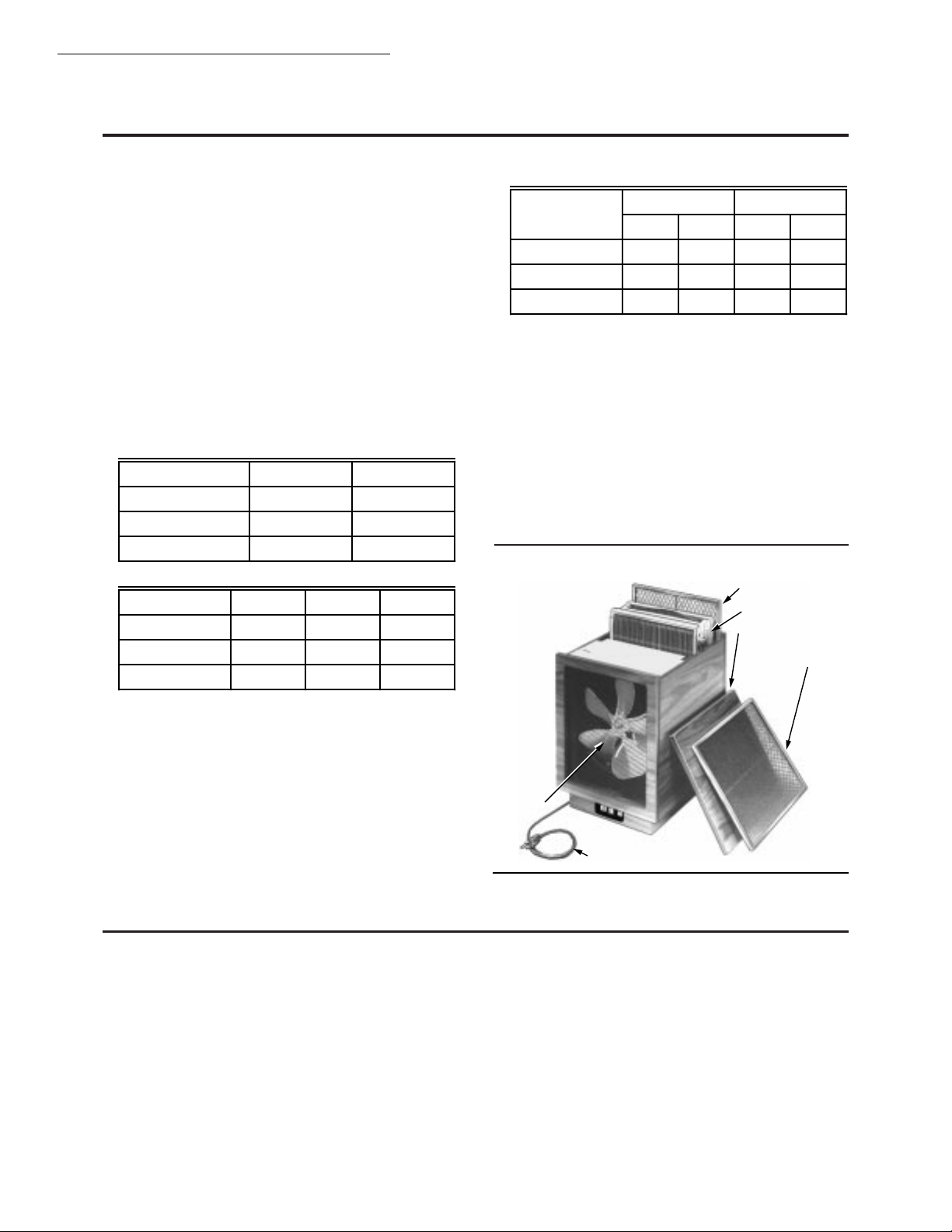
Fig. 1—F59A components.
PREFILTER
CELL
COVER
CARBON
POSTFILTER
FAN
When purchasing replacement and modernization products from your TRADELINE® wholesaler or your full service distributor, refer to
the TRADELINE Catalog or price sheets for complete ordering number, or specify—
1. Order number.
2. Cabinet color—walnut or light oak (light oak not available in Canada).
3. Voltage.
4. Accessories, if required.
If you have additional questions, need further information, or would like to comment on our products or services, please write or phone:
1. Your local Honeywell Home and Building Control Sales Office (check white pages of your phone directory).
2. Home and Building Control Customer Logistics
Honeywell Inc., 1885 Douglas Drive North
Minneapolis, Minnesota 55422-4386 (612) 951-1000
In Canada—Honeywell Limited/Honeywell Limitee, 740 Ellesmere Road, Scarborough, Ontario M1P 2V9. International Sales and
Service offices in all principal cities of the world. Manufacturing in Australia, Canada, Finland, France, Germany, Japan, Mexico,
Netherlands, Spain, Taiwan, United Kingdom, U.S.A.
68-0086—5 2
POWER CORD AND PLUG
M9680
Ordering Information
Page 3
WHEN USING THIS PRODUCT…
Read these instructions carefully. Failure to follow them
could damage the product or cause a hazardous condition.
UNPACK ELECTRONIC AIR CLEANER
Check that all components are included. The electronic
air cleaner is shipped assembled. See Fig. 1.
SET UP ELECTRONIC AIR CLEANER
■ Position the F59A so:
• the airflow in and out of the air cleaner is not
blocked or partially obstructed.
• the discharge air does not cause uncomfortable
drafts for any occupant.
• the power cord does not interfere with normal occupant traffic.
■ Remove and discard the cardboard liner next to the
electronic air cleaner cell.
■ Remove the cell and carbon postfilter from the cabinet;
remove and discard the plastic cover from the carbon
postfilter.
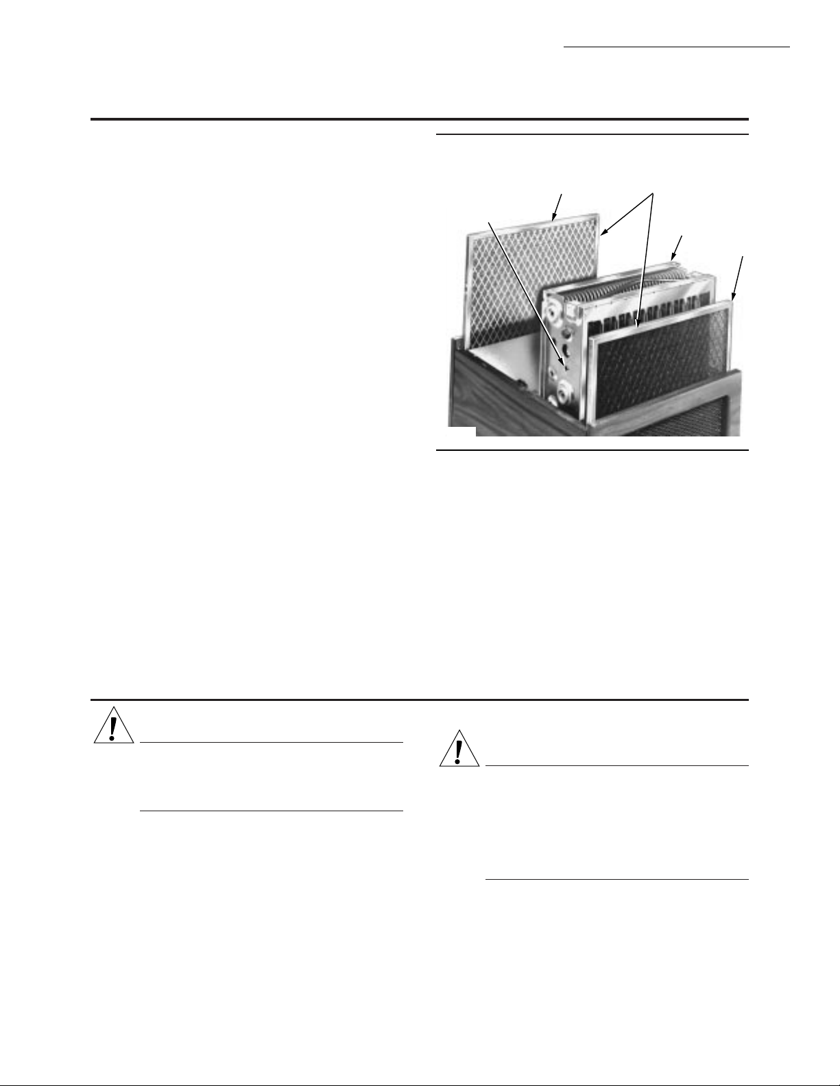
■ Replace the cell and the carbon postfilter. Make sure
cell is placed correctly, with directional arrows pointing
toward center of air cleaner cabinet. The cell directional
arrow is located on the side of the cell. The prefilter and
carbon postfilter should be placed with the wire mesh
toward the center. See Fig. 2.
■ Plug power cord into standard grounded outlet.
OPERATION OF ELECTRONIC AIR CLEANER
■ Select desired airflow rate with three-speed power
switch—LO, MED or HI. For maximum air cleaning
SETUP AND OPERATION • SERVICE
Setup and Operation
Fig. 2—Make sure cell and filters are placed
correctly.
DIRECTIONAL ARROW
(POINTING TOWARD
CENTER OF
CABINET
M9683
benefit, leave switch on HI at all times. For quiet
operation, use LO setting. Neon light and fan should be
on whenever air is running.
■ Move power switch to OFF to turn off electronic air
cleaner; neon light and fan will go off.
NOTE: An arcing (snapping) sound may be heard occa-
sionally as air cleaner operates. This sound means air
cleaner is working as it should, collecting large airborne
dust particles.
CARBON
POSTFILTER
INSERT FILTER WITH
WIRE MESH TOWARD
CENTER OF UNIT
CELL
PREFILTER
F59A
CAUTION
SHARP EDGES.
CAN CAUSE PERSONAL INJURY.
Handle the cell carefully to avoid cuts from the
sharp metal edges.
CLEANING THE CELL AND PREFILTER
Clean the cell and prefilter regularly—every one to six
months. Variables such as number of occupants, pets,
activities and smoking will determine how often cleaning is
required. Use the wash reminder schedule included with
the air cleaner to help establish and maintain a regular
cleaning schedule.
The cell can be washed in many automatic dishwashers,
by soaking in a tub or a do-it-yourself coin operated car
wash. The prefilter can be vacuumed, brushed or soaked in
a tub. Do not wash the filter in the dishwasher or carwash.
Service
Automatic Dishwasher
CAUTION
BURN HAZARD.
CAN CAUSE PERSONAL INJURY.
Allow the cell to cool in the dishwasher at the end
of the wash cycle or wear protective gloves to
avoid burns. Hot water can accumulate in the
tubes supporting the collector plates. Tip the cell
so these tubes will drain.
IMPORTANT:
• Check you dishwasher owner manual. Some manufacturers do not recommend washing electronic cells
in their dishwasher.
• If the dishwasher has upper and lower arms, carefully position the cell to allow good water circulation.
3 68-0086—5
Page 4
F59A
SERVICE
• Be careful to avoid damaging or bending the cell
plates when placing the cell in the dishwasher. If
bent, arcing will result.
• A very dirty cell, especially from tobacco or cooking
smoke, can discolor the plastic parts and lining of the
dishwasher. The discoloration is not harmful. To
minimize it, wash the cell more frequently or try a
different brand of detergent.
• Do not allow the dishwasher to run through the dry
cycle. This will bake on any contaminants not removed during the wash cycle and reduce air cleaner
efficiency.
1. Put the cell on the lower rack of the dishwasher with
the directional arrow pointing up. It may be necessary to
remove the upper rack. Do not block water flow to the
upper arm, if provided on dishwasher.
2. Using the detergent that works best for normal
dishwashing, allow the dishwasher to run through the complete wash and rinse cycle. Do not use the dry cycle. To
avoid burns, let the cell cool completely before removing,
or wear protective gloves when removing the cell. Remember that water may be trapped in the tubes that support the
collector plates. Tip the cell so these tubes can drain.
3. Wipe the ionizer wires and contact board on end of
cell with a small, damp cloth, using your thumb and forefinger.
4. Inspect the dishwasher. You may wish to rerun the
wash and/or rinse cycle with the dishwasher empty if you
see dirt or residue from washing the cell. If dirt or residue
seems excessive, wash the cell more often or try a different
detergent.
5. Inspect the cell for bent plates; bend back to normal
to prevent arcing.
Soaking in Tub
CAUTION
HAZARDOUS CHEMICAL.
CAN CAUSE PERSONAL INJURY.
Do not splash the detergent solution in eyes. Wear
rubber gloves to avoid prolonged detergent contact with skin. Keep detergent and solution out of
reach of children.
NOTE: Always wash the cell first, then the prefilter, to
keep heavy prefilter lint from getting caught in the cell.
5. Rinse the cell with a hard spray of very hot water;
rinse the tub clean, then fill the tub with clean hot water and
soak for 5 to 15 minutes. Rinse until water draining from
the cell no longer feels slippery. Rinse the filter with a
gentle spray of hot water.
6. Soak cell and filter in a final clear water rinse for ten
minutes.
7. Wipe the ionizer wires and contact board on end of
cell by using your thumb and forefinger and holding a
small, damp cloth.
Car Wash
Use the hand sprayer at a coin-operated car wash to
wash the cell. Hold the nozzle at least 2 ft [0.6m] away from
the unit to avoid damage from the high pressure stream of
water. Follow the same sequence of wash and rinse as
recommended for cars. However, do not wax the cell. Rinse
until the water draining from the cell no longer feels slippery.
REINSTALLING CELL, PREFILTER AND
CARBON POSTFILTER
■ Inspect the cell for broken ionizer wires and bent collec-
tor plates. Repair as necessary.
■ Slide the dry filter into the filter guides, with directional
arrow pointing toward the center of the electronic air
cleaner cabinet. The directional arrow is very small, and
is located on the end of the filter frame. See Fig. 2.
■ Gently vacuum the inside and outside of the air cleaner
cabinet with the brush attachment of vacuum cleaner, or
dust with a soft cloth.
■ Slide in the dry cell so the directional arrow (located on
the side of the cell) points toward the center of the air
cleaner cabinet.
■ Replace the carbon filter if necessary. This filter slides in
or out of the guides easily.
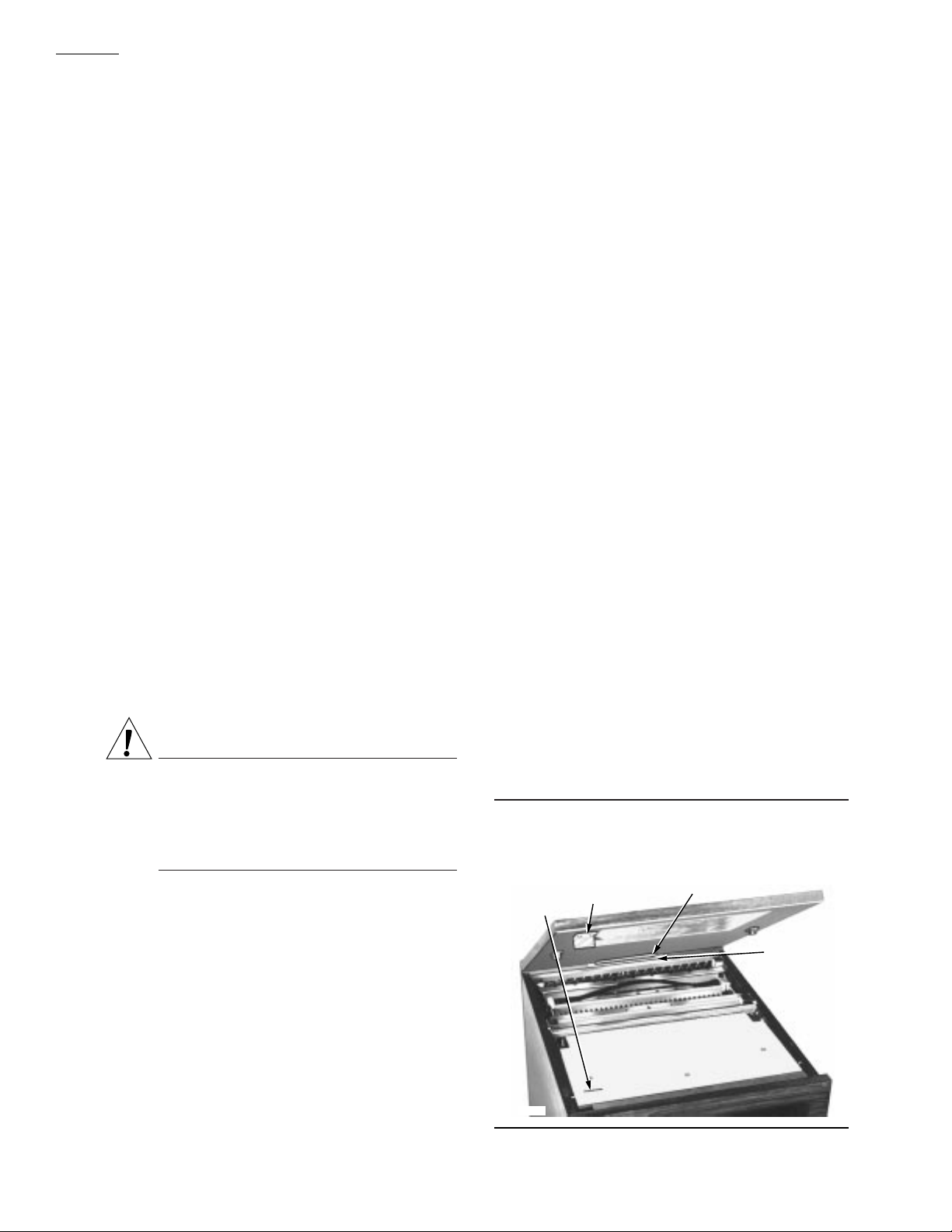
■ Replace the cover on the cabinet. The metal tab on the
cover must fit in the slot at the end of the cabinet, and the
interlock under the cover must connect with the air
cleaner cabinet for operations. See Fig. 3.
Fig. 3—Cover must fit correctly for operation.
THE METAL TAB ON
THE COVER MUST
FIT IN THE SLOT
METAL
TAB
SLOT
METAL
TAB
INTERLOCK
THE INTERLOCK UNDER THE
COVER MUST CONNECT WITH
THE AIR CLEANER CABINET
1. Use a container such as a laundry tub or trash container that is large enough to hold the cell. Sharp corners on
the cell can scratch the surface of a bathtub.
2. Dissolve about 3/4 cup automatic dishwashing detergent in enough hot water to cover the cell. If the detergent
does not dissolve readily, or forms a scum on the water, try
another brand, or use softened water.
3. After the detergent has completely dissolved, place
the cell in the container and let soak for 15 to 20 minutes.
Agitate up and down a few times, and remove.
4. Next, wash the prefilter the same way. Empty and
rinse the wash container.
68-0086—5 4
M9682
INTERLOCK
SLOT
Page 5

F59A
OIL
INDENTATIONS
M9681
SERVICE • ELECTRICAL TROUBLESHOOTING
■ Turn on the air cleaner. If the cell and filters are wet, the
neon light may not come on; you may also hear arcing.
If the arcing is annoying, simply turn off the air cleaner
for two to three hours or until the cell is dry. Remove wet
cell to hasten drying.
IONIZER WIRE REPLACEMENT
Broken ionizer wires can cause a short to ground, often
resulting in visible arcing or sparking. The cell should not
be used until the pieces of broken wire are removed. It can
Fig. 4—Install new ionizer wire by hooking
eyelets over spring connectors.
be used temporarily with one wire missing, although the
wire should be replaced as soon as possible. See the Parts
List, for order number.Replacement wires are supplied cut
to length with eyelets on both ends for easy installation. To
install:
■ Hook the eyelet on one end of the wire over the spring
connector on one end of the cell. See Fig. 4. Be careful
to avoid damaging the spring connector or other parts of
the cell.
■ Hold the opposite eyelet with a needlenose pliers and
stretch the wire the length of the cell. Depress the
opposite spring connector and hook the eyelet over it.
OILING THE FAN MOTOR
Oil the fan motor once a year for smooth operation:
■ Turn off air cleaner switch; unplug power cord.
■ Remove cover and cell.
■ Put two drops of electric motor oil in each of two oil
indentations in fan motor. See Fig. 5.
■ Replace cell with directional arrow (on side of cell)
pointing toward center of air cleaner cabinet; replace
carbon filter.
■ Plug in power cord; turn on the air cleaner again.
Fig. 5—Oil fan motor yearly.
SPRING
CONNECTORS
PRESS
DOWN
M1540
IONIZER
WIRE
IONIZER
WIRE
EYELETS
NEEDLENOSE
PLIERS
W ARNING
ELECTRIC SHOCK HAZARD.
CAN CAUSE PERSONAL INJURY OR
EQUIPMENT DAMAGE.
The following procedures expose hazardous live
parts. Disconnect power supply between checks
and proceed carefully.
Electrical T roubleshooting
CAUTION
The following instructions are for use by qualified
personnel only.
TOOLS AND EQUIPMENT
Troubleshooting the electronic air cleaner requires only
a few tools:
• Needlenose pliers (for stringing ionizer wires).
• Test meter with high voltage probe (10 kV minimum).
5 68-0086—5
Page 6

F59A
ELECTRICAL TROUBLESHOOTING
TROUBLESHOOTING PROCEDURE
CAUTION
ELECTRIC SHOCK HAZARD.
CAN CAUSE PERSONAL INJURY.
Always turn off power before troubleshooting.
Fig. 6—Troubleshooting the F59A.
START
MAKE SURE
ELECTRONIC CELL
IS CLEAN, DRY AND
PROPERLY
INSTALLED.
MAKE SURE
PREFILTER AND
CARBON POSTFILTER ARE
PROPERLY
INSTALLED.
REPLACE THE
COVER AND TURN
THE AIR CLEANER
ON. CHECK LO,
THEN MED, THEN HI
SPEEDS.
CHECK FAN AND
NEON LIGHT.
BOTH
ON
OPEN COVER; PUSH
IN INTERLOCK
SWITCH; WITH
PLASTIC-HANDLED
SCREWDRIVER,
SHORT FROM CELL
FRAME TO A HOT
COLLECTOR
PLATE.
ELECTRONIC AIR
CLEANER IS OK.
3
YES
TROUBLESHOOTING F59A ELECTRONIC AIR CLEANER
THESE SERVICING INSTRUCTIONS ARE FOR USE BY QUALIFIED PERSONNEL
ONLY. TO REDUCE RISK OF ELECTRIC SHOCK, DO NOT PERFORM ANY
SERVICING OTHER THAN CONTAINED IN THE OPERATING INSTRUCTIONS
UNLESS YOU ARE QUALIFIED TO DO SO.
CHECK LINE
POWER; CORRECT
AS NEEDED.
BOTH
OFF
JUMPER FAN
LIGHT
SWITCH CONTACTS
ON
- FOR EACH SPEED
IN TURN.
FAN
ON
REMOVE CELL.
REPLACE COVER.
CHECK NEON
NO
LIGHT.
LIGHT
INSPECT CELL FOR
– BENT COLLECTOR
PLATES
– BROKEN IONIZER
WIRES
– DIRT ON
INSULATORS
– DAMAGED
CONTACT TABS
WITH OHMMETER
CHECK FOR SHORT
BETWEEN
– CELL FRAME AND
IONIZER SECTION
– CELL FRAME AND
COLLECTOR
SECTION
ON
NO CELL
DAMAGED NOTED
INFINITE
RESISTANCE
CELL OK.
The troubleshooting chart shows how to quickly isolate
a problem in the air cleaner. See Figs. 6 through 10.
The solid state power supply assembly provided in this
air cleaner has no field-serviceable components. If troubleshooting indicates a power supply assembly problem, replace the entire power supply assembly. See Parts List
section, for order number.
TO USE THIS CHART:
1. Be sure to follow the steps sequentially.
2. Each time you isolate and fix a problem, go back to START.
3. Repeat ALL the steps until the air cleaner checks out OK.
WARNING
RISK OF ELECTRIC SHOCK
CHECK LAMP/FAN. REPLACE SWITCH.
FAN
ON
FAN
OFF
LIGHT
OFF
CELL
DAMAGED
CELL
SHORTED
REPLACE SWITCH.
TURN OFF POWER.
MAKE SURE SHAFT
ON FAN MOTOR
ROTATES FREELY.
REPLACE MOTOR IF
NECESSARY.
REMOVE COVER.
CHECK FOR
CORRECT INPUT
VOLTAGE BETWEEN
P1 AND P2
TERMINALS ON
POWER SUPPLY.
REPAIR OR
REPLACE CELL.
REPLACE CELL.
VOLTAGE
CORRECT
VOLTAGE
NOT
CORRECT
CHECK VOLTAGE
ACROSS NEON
LEADS.
REPLACE LIGHT.
CHECK WIRING
BACK THROUGH
SWITCH, POWER
CORD, AND OUTLET
TO CIRCUIT
BREAKER OR FUSE.
LAMP
OFF
VOLTAGE
ABOVE
120 Vdc
1
LAMP ON
VOLTAGE
BELOW
120 Vdc
LIGHT OK. REPLACE
COMPLETE POWER
SUPPLY.
2
1
NEON LIGHT MUST BE REPLACED TO ENSURE PROPER AIR CLEANER OPERATION.
2
ELECTRONIC COMPONENTS ON POWER SUPPLY BOARD ARE NOT FIELD REPLACEABLE. ATTEMPTED SERVICE WILL DAMAGE BOARD.
A HIGH VOLTAGE METER CAN BE USED TO MEASURE IONIZER AND COLLECTOR VOLTAGE.
3
68-0086—5 6
M1312B
Page 7

ELECTRICAL TROUBLESHOOTING
3
Fig. 7—Push screwdriver down to close interlock switch (left); short from cell frame to hot collector
plate to product arcing (right) as instructed in Fig. 6.
PUSH SCREWDRIVER DOWN
TO CLOSE INTERLOCK SWITCH
CELL
FRAME
COLLECTOR
PLATES
F59A
M5637
Fig. 8—Internal schematic for 120 Vac, 60 Hz F59A.
NEON
GREEN
GR OU ND
LIGH T
ON-OFF/
3 SPEED
FAN
SWITCH
2
2
ON (C OM)
1
MED
LOW
(L)
BLACK
WHITE
HI
4
3
2
1
BLACK
BLACK
BLUE
RED
YELLOW
GREEN
FAN
MOTOR
RED -IONIZER
BLACK-COLLECTOR
N EON L AMP
GROUND
ON (COM) SW I TCH CONTACT IS MADE IN
1
ALL SWITCH POSITIONS EXC EPT OFF.
INTERLO CK SAFETY SWIT CH ON CO VER.
2
M5634
POWER SUPPLY
P3
P4
P5
P2
P1
M315
7 68-0086—5
Page 8

F59A
2
ELECTRICAL TROUBLESHOOTING
Fig. 9—Internal schematic for 220 Vac, 50 Hz F59A.
NEON
LIGH T
YELLOW
GREEN
RED -IONIZER
BLACK-COLLECTOR
N EON L AMP
GROUND
POWER SUPPLY
P3
P4
P5
BLUE
GREEN /YEL LOW
BROWN
BROWN
GR OU ND
ON-O F F/
3 SPEED
FAN
SWITC H
BLUE
GREEN /
YELLOW
2
2
ON (C OM)
1
ORA NGE
MED
LOW
A6
BLACK
A5
BLACK
D2
HI
BLACK
BLUE
C2
RED
B2
WHITE
WHI T E
When measuring high voltage, use a good quality multimeter and HV probe. When measuring ionizer and collector
voltage, they should be between 6900 and 7800 Vdc.
REDUCING OZONE ODOR
CAUTION
ELECTRIC SHOCK HAZARD.
CAN CAUSE PERSONAL INJURY.
Always disconnect power before working on power
supply.
Only a trained service technician should perform
the following procedure.
The electronic air cleaner generates a small amount of
ozone in normal operation. During the first week or two of
operation, the amount may be higher because of sharp
edges on some of the new high voltage metal parts. Normal
use dulls these edges in a short time.
P2
P1
ON (COM) SW I TCH CONTACT IS MADE IN
FAN
MOTOR
1
ALL SWITCH POSITIONS EXC EPT OFF.
INTERLO CK SAFETY SWIT CH ON CO VER.
2
M315
The average person can detect the odor of ozone in
concentrations as low as 0.003 to 0.010 parts per million
(ppm). The electronic air cleaner contributes 0.005 to
0.010 ppm of ozone to the indoor air. The U.S. Food and
Drug Administration and Health and Welfare Canada recommend that indoor ozone concentration should not exceed 0.050 ppm. As a comparison, the outdoor ozone level
in major cities is sometimes as high as 0.100 ppm. However, if desired, the ozone generated by the air cleaner can
be reduced by clipping out the J2 jumper on the power
supply. This will reduce ozone production about 20 to 25
percent, and reduce efficiency about 7 to 10 percent depending on actual airflow delivered by the furnace blower.
a. Turn off power to the air cleaner; tip unit upside
down and remove bottom plate to access power
supply.
b. Find the J2 jumper on the power supply, and clip it
out. See Fig. 11.
c. Replace the air cleaner bottom plate; turn on power.
Regular replacement of the carbon filter (every 3 to 6
months) will also help reduce ozone odor.
68-0086—5 8
Page 9

ELECTRICAL TROUBLESHOOTING
Fig. 10—Use an ohmmeter to check the cell for short circuits as instructed in Fig. 6.
COLLECTOR
TERMINAL
IONIZER
TERMINAL
COLLECTOR
TERMINAL
M6155
F59A
Fig. 11—Clip out the J2 jumper to reduce ozone production about 20 to 25 percent.
J2 JUMPER. CLIP OUT TO REDUCE
OZONE PRODUCTION
P3
P4
J2
2
4
3
1
P2
P1
CABLE CLAMP CLIP
M6148
9 68-0086—5
Page 10

F59A
PARTS LIST
Parts List
Part Number
Number Description 120 Vac, 60 Hz 220 Vac, 50 Hz
1 Prefilter 190356 190356
2 Electronic Cell FC37A1130 FC37A1130
3 Contact Panel 138889A 138889A
4 Solid State Power Supply 203362J 203362W
5 Neon Light 190340 190340
6 Fan Motor 203634 203635
7 Fan Blade 205345 205345
8 Interlock Switch 190070 190070
9 Cell Removal Handle 190358 190358
10 Cell Handle Fastener (2) 190359 190359
11 Cover Latches (male) (2) 190361 190361
12 Cover Latches (female) (2) 190362 190362
13 Mounting Feet (4) 190360 190360
14 Interlock Actuator Bracket 197675 197675
15 Control Switch 190382 196934
16 Carbon Postfilter 203638 203638
Parts and Accessories Not Illustrated
Part Number
Description 120 Vac, 60 Hz 220 Vac, 50 Hz
Casters and Hardware 190364A 190364A
Ionizer Wires (multiples of 5) 136434BA 136434BA
Interlock Switch Assembly 4074EBC 4074EBC
68-0086—5 10
Page 11

Fig. 12—F59A parts are keyed to parts list.
F59A
PARTS LIST
10
9
12
14
6
7
1
2
11
16
8
3
5
15
4
13
M3151
This equipment is a class B digital apparatus which complies with Canadian Radio Interference Regulations, CRC c.
1374.
11 68-0086—5
Page 12

Home and Building Control Home and Building Control Helping You Control Your World
Honeywell Inc. Honeywell Limited—Honeywell Limitée
1985 Douglas Drive North 740 Ellesmere Road
Golden Valley, MN 55422 Scarborough, Ontario
M1P 2V9
68-0086—5 12Printed in U.S.A.
Printed in U.S.A.
QUALITY IS KEY
 Loading...