

Honeywell EW451 Series, EW447A0100, EW450A0100, EW447A1200, EW450A1200 Installation And Setup
...Page 1
Honeywell y All rights reserved EN0H-2601GE25 R0413
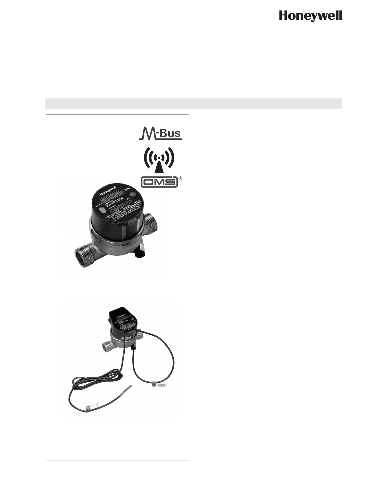
EW447-EW452 Series
Mechanical Heatmeters
FOR HEATING AND COOLING APPLICATIONS
PRODUCT DATA
Fig. 1. EW447 (cables removed)
Fig. 2. EW447F (with RF)
CONTENTS
Contents ............................................................................... 1
General ................................................................................. 2
Application .......................................................................... 2
Features ............................................................................. 2
Design ................................................................................ 2
Materials ............................................................................. 2
Approvals ........................................................................... 2
Technical Details ................................................................. 2
Specifications .....................................................................2
Flow data ............................................................................3
Sizing .............................................................................. 3
Function ............................................................................. 3
Installation and Setup ......................................................... 4
Software .......................................................................... 4
Communication and Readout ............................................. 5
Typical Readout Applications ......................................... 5
Identification ....................................................................... 6
Dimensions ........................................................................ 7
Ordering Details ................................................................... 8
Ordering Information .......................................................... 8
Scope of Delivery ............................................................... 9
Accessories ........................................................................ 9
Diagrams ............................................................................ 11
Measuring Accuracy ......................................................... 11
Flow Diagram ................................................................... 12
Page 2

EW447-EW452 SERIES MECHANICAL HEATMETERS
EN0H-2601GE25 R0413 2 Honeywell y All rights reserved
GENERAL
Application
Honeywell EW447-452 Series mechanical meters are compact
heat or chilled water meters with electronic measurement
based on the multijet principle, consisting of an electronic
energy calculator, a multijet flow sensor and two temperature
sensors.
They are used for metering of hydronic heating and/or cooling
energy in hydronic systems based on volume, supply and
return temperature.
EW447-449 models are suitable for energy metering in heating
systems (‘heat metering’).
EW450-452 models are suitable for energy metering in
heating, cooling or combined systems.
Features
• Approval for meter with dynamic range of 100:1 (qp:qi)
in class 2
• Lithium battery, battery lifetime 12 years
• Optical interface as standard
• Rotatable calculator
• Optionally with integrated radio, Open Metering
Standard, 868MHz
Design
EW447-452 Series mechanical meters consist of:
• Electronic energy calculator with power supply and fixed to
mechanical flow sensor
• Factory fitted supply and return temperature sensors
• Optionally M-Bus or pulse output function
• Flow sensor with external threads according to ISO228
(DN15…DN40) or flanges PN16 (DN32…DN100)
• EW45x versions with potted electronics
Materials
• Front panel of energy calculator made of dark grey plastic
with laser markings for approval, flow and other product
information
• Housing of energy calculator made of dark grey plastic
• EW447 and 452: housing of flow sensor made of unpainted
brass
• EW448, 449, 451 and 452: housing of flow sensor made of
brass, painted dark grey
Approvals
Heating
• DN15…20: MID class 2 (DE-07-MI004-PTB030) and
EN1434 (22.52 / 00.02)
• DN25…40: MID class 2 (DE-09-MI004-PTB001) and
EN1434 (22.52 / 06.02)
• DN50…100: EN1434 (22.52 / 01.02)
TECHNICAL DETAILS
Specifications
Sizes DN15…DN100
qp0.6…60m³/h
Medium Water, quality to VDI2035
Medium temperature 5...90°C
Ambient temperature 5…55°C
Storage temperature -20…55°C
Operating pressure max. 16bar
Protection class IP54 (EW44x)
Measuring process Fully electronic compact heat meter
with direct impeller scanning
(EW447, 448, 450 and 451) or
impeller scanning via magnetic
coupling with sensors (EW449 and
452)
Display LCD, 7-digit
Display units MWh, kWh, GJ, MJ, kW, m³/h, l/h,
m³ and l
Display values 9 999 999, 999 999.9, 99 999.99,
9 999.999
Values displayed Power, energy, flow rate, tempera-
ture, energy on readout date,
readout date
Measuring cycle
volume
16s
Measuring cycle
temperature
32s
Temperature difference
max. 147K
Starting temperature
difference
0.25K
Absolute temperature
measuring range
0…150°C
Temperature sensors Pt500 with 2-wire leads
Operating voltage 3.0V
Ambient class Class C + M1
Battery lifetime 10 + 2 years
Interfaces Optical
Optional interfaces
Page 3
EW447-EW452 SERIES MECHANICAL HEATMETERS
Honeywell y All rights reserved 3 EN0H-2601GE25 R0413
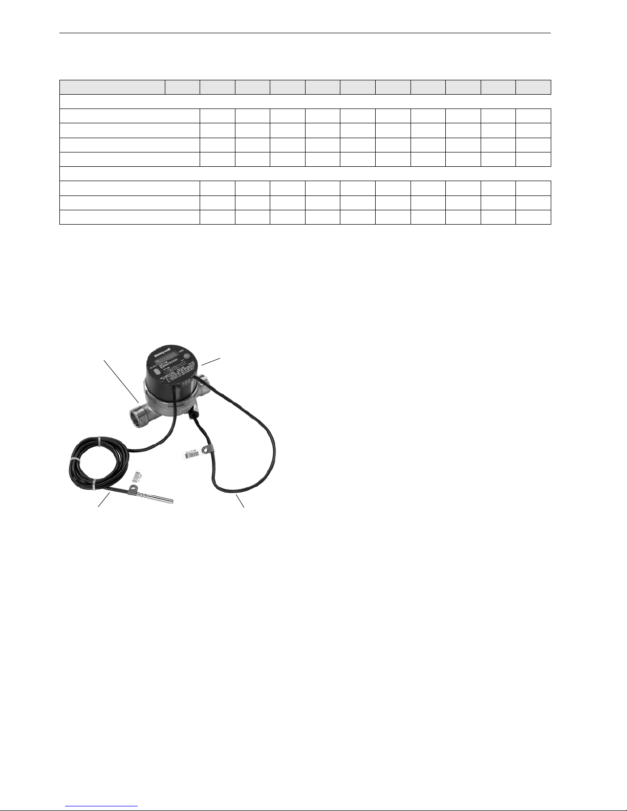
Flow data
Table 1. Flow rates EW447-452 Series
Sizing
• EW447-452 Series mechanical meters should be selected in such a way that typical system flow rates are between approved
minimum (qi) and maximum flow rate (qs)
• Overload flow rate may be reached for not more than 15 minutes per day
• Flow rates below minimum and above maximum should be avoided
DN 15 15 20 25 25 40 50 65 80 100
Flow rates according to MID
Minimum (qi) l/h 6 15 25 70 120 200 300 500 800 1,200
Nominal (qp) m³/h 0.6 1.5 2.5 3.5 6 10 15 25 40 60
Maximum (qs) m³/h1.2 3 5 7 1220305080120
Dynamic range (qp/qi) 1:100 100:1 100:1 50:1 50:1 50:1 50:1 50:1 50:1 50:1
Additional flow data
Starting flowrate l/h 1.5-2 3-4 5-6 35 60 100 60 60 90 90
Overload flow rate m³/h 50 50 110 140
Pressure loss @ qp 243 243 242 170 190 240 62 142 80 100
Function
Fig. 3. EW447 components
Energy Calculator
The energy calculator (or simply ‘calculator’) contains circuits
for recording flow rate and temperature and for calculating,
logging and displaying data.
The meter can be read from a single line seven-digit display
with units and symbols. A push button provides control of
various display loops. All failures and faults are recorded automatically and displayed on the LCD screen. For protection all
relevant data is saved in a non-volatile memory (EEPROM).
This memory saves measured values, device parameters and
types of error at regular intervals.
Flow Sensor
The multijet technology of the flow sensor permits high
measuring accuracy. Standard place of installation is return
pipeline. For installation in supply a different version has to be
used. Meters cannot be reconfigured from return to supply
pipeline usage in the field.
Power Supply
Non replaceable lithium battery 3.0V DC with 10 + 2 year lifetime (10 year nominal lifetime, 1 year for storage an 1 year
buffer). Nominal lifetime relates to normal usage. Battery lifetime is decreased by shorter readout intervals, longer data telegrams, etc.
Temperature sensors
EW447-452 Series mechanical meters are supplied with
installed Pt500 temperature sensors with 2-wire leads,
Ø5.2mm. The temperature sensors are permanently installed
to the meter and cannot be replaced. Sensor cable lengths are
as follows:
Interfaces
EW447-452 Series mechanical meters are equipped with a
ZVEI optical interface for communication and testing as standard. Further all meters are available with either RF, MBus or
pulse output. For more details on interfaces see chapter
“Communication and Readout” below.
Energy calculator
Return temperature
Flow sensor
Supply temperature
sensor
sensor
EW447 and 450 • Supply: 1.5m
• Return: 0.4m with sensor installed in
housing of flow sensor
EW448 and 451 • Supply: 3.0m
• Return: 1.5m with sensor installed in
housing of flow sensor
EW449 and 452 • Supply: 6m
• Return: 6m
Page 4
EW447-EW452 SERIES MECHANICAL HEATMETERS
EN0H-2601GE25 R0413 4 Honeywell y All rights reserved
Installation and Setup
Medium
Heat meters generally are only approved for metering of water
and not for water glycol mixtures or fluids other than water.
During measurement meter must be completely filled with
water.
Flow Sensor
EW447-452 Series mechanical meters must be installed in the
return pipeline. When installed in the supply pipeline measurements are either unreliable, inaccurate or nonexistent. Pipeline
configuration cannot be changed in the field.
• Avoid installation at highest point of system or system part as
air may be trapped in meter
• It is recommended to place a ballvalve before and after the
heat meter for easy replacement
• Various fittings are available for sizes DN15…DN40
• Ball valves and fittings see Accessories on page 9f
• Further it is recommended to place a strainer before the
meter to avoid dirt entering the flow sensor
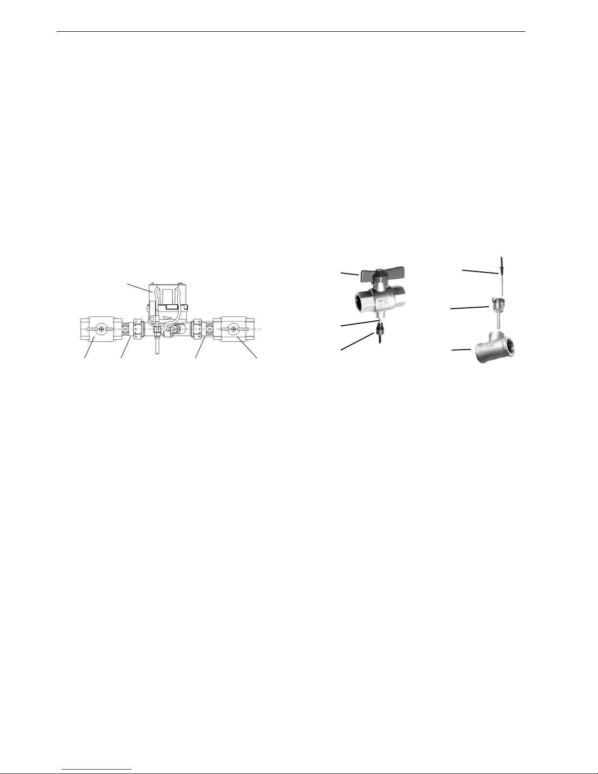
Fig. 4. Flow sensor installation
Calming legs
• EW447, 448, 450 and 451: calming legs before or after meter
are not required
• EW449 and 452: a calming leg of 3 x DN before meter is
recommended, in case of a T-piece or bend before the meter
a length of 5 x DN is recommended
Installation position
• EW447 and 450 may be installed in any position
• EW448, 449, 451 and 452 may only be installed in horizontal
position
Temperature Sensors
• Temperature sensors have to be installed like for like.
Example: if one temperature sensor is installed directly in the
flow, the second temperature sensor also has to beinstalled
directly in the flow
• Temperature sensors may only be installed directly in the
flow or, for sizes DN65 and larger, with MID approved sensor
pockets. See Accessories
• Sensor pockets can also be used for smaller sizes, although
installation directly in the flow is preferred
• Various fittings and other accessories are available for
temperature sensor installation, see Acessories on page 9f
Meter (exemplary)
Ball valve Connection fitting Connection fitting Ball valve
Fig. 5. Temperature sensor
installation with ballvalve
Fig. 6. Temperature sensor
installation with sensor
pocket
Ball valve
Temperature
Temperature sensor
sensor
installation kit
Sensor
Temperature
sensor
T-piece
pocket
Software
In general it is not necessary to parametrise EW447-452
meters in the field unless standard values should be changed.
Such changes can be done with the HydroSet software which
you can download free of charge from
http://metering.ecc.emea.honeywell.com/.
Page 5

EW447-EW452 SERIES MECHANICAL HEATMETERS
Honeywell y All rights reserved 5 EN0H-2601GE25 R0413
Communication and Readout
Model Overview
EW447-452 Series mechanical meters have an optical interface on the front panel and optionally one additional internal interface.
Model OS# starting Sizes available
A type: no interface EW44xA…, EW45xA… All sizes
F type: for RF networks EW447F…, EW450F… DN15…20
M type: for M-Bus networks EW44xM…, EW45xM… All sizes
P type: with pulse output EW44xP…, EW45xP… All sizes
Communication Options
Optical interface on front panel
Included as standard in all EW447-452 Series mechanical
meters. ZVEI interface, M-Bus protocol, for readout and
parametrisation. Required for access to meter:
• Bluetooth optohead (EWA3001799)
• PC with HydroSet software
Onboard RF
Transmission interval 64 seconds, suitable for walk by and
fixed RF networks. Open Metering Standard protocol,
frequency 868MHz.
Onboard M-Bus interface
According to EN1434-3, data reading and parametrisation via
two wires with polarity reversal protection.
Onboard pulse output
Two open collector outputs for energy and volume of heat
meters and cooling energy and heat energy for heat and chilled
water meters.
Typical Readout Applications
Direct Readout
The meter is visited at its point of installation and desiredvalues
are directly read off display and recorded manually.
Recommended model: A model
Alternative
Any EW447-452 Series mechanical meter allows direct
readout over the display.
Wired M-Bus Network
The meter is attached to a wired M-Bus network which allows
remote configuration and readout over the M-Bus master.
Recommended model: M model
The factory fitted M-Bus interface allows direct wiring to MBus
networks.
Wireless Networks
Generally there are three kinds of wireless networks:
• Wired M-Bus networks which use RF links for selected parts
of the network. Normally an RF capable meter transmits to
RF/M-Bus converter EW535M0131 which in turn is wired to
an M-Bus master unit
• Mobile RF networks, also called ‘walk by’. An RF capable
meter is read out by a person walking or driving past the
meter and equipped with a suitable receiver
• Fixed RF networks. An RF capable meter is read out by a
permanently installed receiver which automatically transmits
the data on to an FTP server
All wireless networks mentioned above use the same kind of
meter, i.e. all RF capable meters listed below are suitable for
use in partially wireless M-Bus networks as well as mobile and
fixed RF networks.
Recommended model: F model
The meter is equipped with an onboard RF interface which
enables the meter to be attached to a suitable RF network.
Alternative : M model + EW9100AEZ001
The M-Bus interface allows direct wiring to external RF trans-
mitter EW9100AEZ001.
Page 6

EW447-EW452 SERIES MECHANICAL HEATMETERS
EN0H-2601GE25 R0413 6 Honeywell y All rights reserved
Pulse Output Signal
The meter is attached to another device which is capable of
counting pulses or a converter which converts the pulses into
another signal.
Recommended model: P model
The onboard pulse output allows direct wiring to a suitable
device. Pulse unit and value cannot be changed.
Setup
On board RF
To activate RF function in the field the red pushbutton on the
front side of the meter has to be pushed once. RF can be deactivated with HydroSet software.
On board M-Bus
No field setup required at meter itself. M-Bus parametrisation,
for example primary address setting, can be done via M-Bus
master unit.
Identification
All EW447 – EW452
• Dark grey calculator housing with Honeywell logo and OSNumber starting with ‘EW4xx…’ lasered onto front panel
• 7-digit LCD display
• Models with MID approval: CE mark and MID approval on
centre of front panel
• Models with EN1434 approval: CE mark and EN1434
approval mark on front panel
• Serial number and meter specs centre bottom
• Red push button
EW447 and EW450
• Unpainted brass flow sensor housing with external threads
on inlet and outlet
• One temperature sensor installed in flow sensor housing
EW448 and EW451
• Dark grey powder coated flow sensor housing with external
threads on inlet and outlet
EW449 and EW452
• Dark red powder coated flow sensor housing with flanges on
inlet and outlet
Fig. 7. Top view of EW447A1200
Page 7

EW447-EW452 SERIES MECHANICAL HEATMETERS
Honeywell y All rights reserved 7 EN0H-2601GE25 R0413
Dimensions
Table 2. Dimensions threaded versions
Table 3. Dimensions flanged versions
NOTE: All dimensions in mm unless stated otherwise.
Length L2 is approximate and varies depending on type of fitting used
Weight is without fittings or any other accessories
Fig. 8. Dimensions DN15…DN20 Fig. 9. Dimensions DN25…DN40
DN Length
L
Length
L2
Meter
thread
Height
H
Height
H1
Diameter
B
Weight
15 110 190 G3/4" B 20 75 63 0.9 kg
20 130 210 G1" B 20 75 63 1 kg
25 260 378 G11/4" B 45 110 63 2.9 kg
40 300 438 G2" B 60 125 63 5.1 kg
Fig. 10. Dimensions DN50…DN100
DN Length
L
Height
H
Height
H1
Flange ∅
D
Bolt ∅
D1
Bolt circle
∅ D1
Weight
50 270 85 125 165 18 125 14 kg
65 300 97 125 185 18 145 18 kg
80 300 102 160 200 18 160 24 kg
100 360 113 170 220 18 180 28 kg
Page 8

EW447-EW452 SERIES MECHANICAL HEATMETERS
EN0H-2601GE25 R0413 8 Honeywell y All rights reserved
ORDERING DETAILS
Ordering Information
Table 4. Standard Configurations
Table 5. Special Configurations
OS-No.:
Item DN size Flowrate qp Length for heating only for heating and
chilled water
EW447-452 Series without interfaces
Threaded
connections
15 0.6 m³/h 110 mm EW447A0100 EW450A0100
15 1.5 m³/h 110 mm EW447A1200 EW450A1200
20 2.5 m³/h 130 mm EW447A2000 EW450A2000
25 3.5 m³/h 260 mm EW448A2800 EW451A2800
25 6.0 m³/h 260 mm EW448A3600 EW451A3600
40 10 m³/h 300 mm EW448A4600 EW451A4600
Flanged
connections
50 15 m³/h 270 mm EW449A5100 EW452A5100
65 25 m³/h 300 mm EW449A5900 EW452A5900
80 40 m³/h 300 mm EW449A6900 EW452A6900
100 60 m³/h 360 mm EW449A7700 EW452A7700
EW447 and 450 Series with RF onboard
Threaded
connections
15 15 m³/h 110 mm EW447F1200 EW450F1200
EW447-452 Series with M-Bus interface
Threaded
connections
15 0.6 m³/h 110 mm EW447M0100 EW450M0100
15 1.5 m³/h 110 mm EW447M1200 EW450M1200
20 2.5 m³/h 130 mm EW447M2000 EW450M2000
25 3.5 m³/h 260 mm EW448M2800 EW451M2800
25 6.0 m³/h 260 mm EW448M3600 EW451M3600
40 10 m³/h 300 mm EW448M4600 EW451M4600
Flanged
connections
50 15 m³/h 270 mm EW449M5100 EW452M5100
65 25 m³/h 300 mm EW449M5900 EW452M5900
80 40 m³/h 300 mm EW449M6900 EW452M6900
100 60 m³/h 360 mm EW449M7700 EW452M7700
EW447-452 Series with pulse output
Threaded
connections
15 0.6 m³/h 110 mm EW447P0100 EW450P0100
15 1.5 m³/h 110 mm EW447P1200 EW450P1200
20 2.5 m³/h 130 mm EW447P2000 EW450P2000
25 3.5 m³/h 260 mm EW448P2800 EW451P2800
25 6.0 m³/h 260 mm EW448P3600 EW451P3600
40 10 m³/h 300 mm EW448P4600 EW451P4600
Flanged
connections
50 15 m³/h 270 mm EW449P5100 EW452P5100
65 25 m³/h 300 mm EW449P5900 EW452P5900
80 40 m³/h 300 mm EW449P6900 EW452P6900
100 60 m³/h 360 mm EW449P7700 EW452P7700
OS-Number
Item DN size Flowrate qp Length for heating only for heating and
chilled water
For fallpipe installation, with M-Bus interface
Threaded
connections
25 3.5 m³/h 135 mm EW6001FM2500
For riser installation, with M-Bus interface
Threaded
connections
25 6.0 m³/h 135 mm EW6001RM3300
40 10 m³/h 150 mm EW6001RM4200
Page 9

EW447-EW452 SERIES MECHANICAL HEATMETERS
Honeywell y All rights reserved 9 EN0H-2601GE25 R0413
Scope of Delivery
• EW447-452 Series mechanical meter consisting of energy calculator and flow sensor
• Supply and return temperature sensors installed to energy calculator
• One or two installation kits EWA3001305 for pipe installation of temperature sensors:
• DN15…20: one kit included (one sensor is already installed in meter housing)
• DN25…50: two kits included
• DN65 and larger: no kits included as immersion pockets are to be used
• Two paper sealings
• Operating and setup instructions
• M-Bus cable (only types with M-Bus)
• Pulse cable (only types with pulse output)
Accessories
Unless stated otherwise accessories are sold in single packs. Table 6 below shows which connection set and ball valve can be
used for which meter size. The meter size is given in the top line and refers to the last four characters of the OS number.
Example: Items listed in the column headed ‘2000’ can be used for ‘EW447A2000’, EW447P2000’ or ‘EW450M2000’ and so on.
Table 6. Cross reference: connection sets and ballvalves / meter
EW4xxX… 0100, 1200 2000 2800, 3600 4600
DN size DN15 DN20 DN25 DN40
Connection size G 3/4” G 1” G 1 1/4” G 2”
Connection sets
Connection set with
externally threaded
tailpiece
1 x EWA1500035 1 x EWA1500042 1 x EWA1500062 1 x EWA1500072
Connection set with
internally
threaded tailpiece
2 x VA7405A015 2 x VA7405A020 2 x VA7405A025 n.a.
Connection set with
Sanpress crimp fitting
2 x VA7404A015 2 x VA7404A020 2 x VA7404A025 n.a.
Connection set with
Mapress crimp fitting
2 x VA7403A015 2 x VA7403A020 2 x VA7403A025 n.a.
Ball valves
Ball valve with additional
port
EWA087HY003 EWA087HY004 EWA087HY005 n.a.
Page 10

EW447-EW452 SERIES MECHANICAL HEATMETERS
Honeywell y All rights reserved 10 EN0H-2601GE25 R0413
Connection Sets for Flow Sensor
NOTE: Union nuts of connection sets EWA15000 are drilled
for sealing with locking wire. Union nuts of connection
sets VA7403, VA7404 and VA7405 are not sealable
with locking wire
Connection Sets for Temperature Sensors
Modules
Other Accessories
Set of two union nuts, two sealings and two externally
threaded brass tailpieces (one pack per meter required) –
sealable with locking wire
For DN15, R1/2” x G3/4” EWA1500035
For DN20, R3/4” x G1” EWA1500042
For DN25, R1” x G1 1/4” EWA1500062
For DN40, R1 1/2” x G2” EWA1500072
Set of union nut, sealing and Sanpress red bronze crimp
fitting (two packs per meter required)
For DN15, for 15mm pipe-Ø VA7404A015
For DN15, for 18mm pipe-Ø VA7404A018
For DN20, for 22mm pipe-Ø VA7404A020
For DN25, for 28mm pipe-Ø VA7404A025
Set of union nut, sealing and Mapress stainless steel
crimp fitting (two packs per meter required)
For DN15, for 15mm pipe-Ø VA7403A015
For DN15, for 18mm pipe-Ø VA7403A018
For DN20, for 22mm pipe-Ø VA7403A020
For DN25, for 28mm pipe-Ø VA7403A025
Set of union nut, sealing and internally threaded red
bronze tailpiece (two packs per meter required)
For DN15, thread Rp1/2” VA7405A015
For DN20, thread Rp3/4” VA7405A020
For DN25, thread Rp1” VA7405A025
Temperature sensor installation kit (bulk pack of 20pcs)
Brass, max. 130°C EWA3001303
Plastic, max. 90°C EWA3001305
Tailpiece for direct connection of temperature sensor to
T-piece with 1/2” internal thread. Temperature sensor
installation kit required
R1/2" external thread,
M10x1 sensor thread
EWA087HY003
R1/4" external thread,
M10x1 sensor thread
EWA354830
Ballvalve with direct connection for temperature sensor.
Temperature sensor installation kit required
DN15, G1/2” internal thread EWA087HY004
DN20, G 3/4” internal thread EWA087HY005
DN25, G1”internal thread EWA087HY006
Brass immersion pockets
35mm, for DN25…32 EWA3002684
52mm, for DN40…65 EWA3002685
85mm, for DN80…100 EWA3004406
Ballvalve with connection for supply temperature sensor
G1/2" internal thread EWA087HY004
G3/4" internal thread EWA087HY005
G1" internal thread EWA087HY006
Tailpiece for connection of supply temperature sensor
R1/2" external thread,
M10x1 sensor thread
EWA087HY003
Brass immersion pocket (for use with MID meters)
35mm, for DN15...32 EWA3002684
52mm, for DN40...65 EWA3002685
85mm, for DN80...125 EWA3004406
External RF module
M-Bus, for all EW773 with
M-Bus module
EW9100AEZ001
M-Bus cable, length=3m
For all EW4xxM EWA812851
Bluetooth optohead
For all EW447-452 EWA3001799
Calibration certificates
For up to five meters EWA3003095A
For six to 20 meters EWA3003095B
For more than 20 meters EWA3003095C
Page 11

EW447-EW452 SERIES MECHANICAL HEATMETERS
Honeywell y All rights reserved 11 EN0H-2601GE25 R0413
DIAGRAMS
Measuring Accuracy
Fig. 11. EW447 and EW450 Series
Fig. 12. EW448 and EW451 Series
Fig. 13. EW449 and EW452 Series
Q1 Q2 Q3
-7
-6
-5
-4
-3
-2
-1
0
1
2
3
4
5
6
7
Flow rate [m
3
/h]
Error [%]
Q1 Q2 Q3
-7
-6
-5
-4
-3
-2
-1
0
1
2
3
4
5
6
7
Flow rate [m
3
/h]
Error [%]
Q1 Q2 Q3
-7
-6
-5
-4
-3
-2
-1
0
1
2
3
4
5
6
7
Flow rate [m
3
/h]
Error [%]
Page 12

EW447-EW452 SERIES MECHANICAL HEATMETERS
Flow Diagram
Fig. 14. Pressure drop diagram EW447-EW452 Series
100
2 4 5 6 7 8 1000
kg/h
Flow rate
9
0.25
0.50.028
0.10
5.0l/sec
3 2 4 5 6 7 8 100009324563 7 8 10000092
1.0
2. 25
10
1
0
0
0
1
0
0
2
3
4
5
6
7
8
9
1
0
0
0
0
2
3
4
5
6
Pressure loss
1
0
P
a
m
b
a
r
qp 2.5 qp 3.5 qp 6 qp 10 qp 15 qp 25 qp 40 qp 60qp 1.5qp 0.6
Environmental and Combustion Controls
Honeywell GmbH
Hardhofweg
74821 MOSBACH
GERMANY
Phone: +49 (6261) 810
Fax: +49 (6261) 81393
http://ecc.emea.honeywell.com
EN0H-2601GE23 R0413
April 2013 (Rev. E)
© 2013 Honeywell International Inc.
Subject to change without notice
Manufactured for and on behalf of the Environmental and Combustion
Controls Division of Honeywell Technologies Sàrl, Z.A. La Pièce 16,
1180 Rolle, Switzerland or its Authorized Representative.
 Loading...