

Honeywell DT8360ACM-SN, DT8360CM-SN Installation Instructions Manual
DT8360CM-SN / DT8360ACM-SN DUAL TEC® Ceiling
Mount Motion Sensor
Installation Instructions
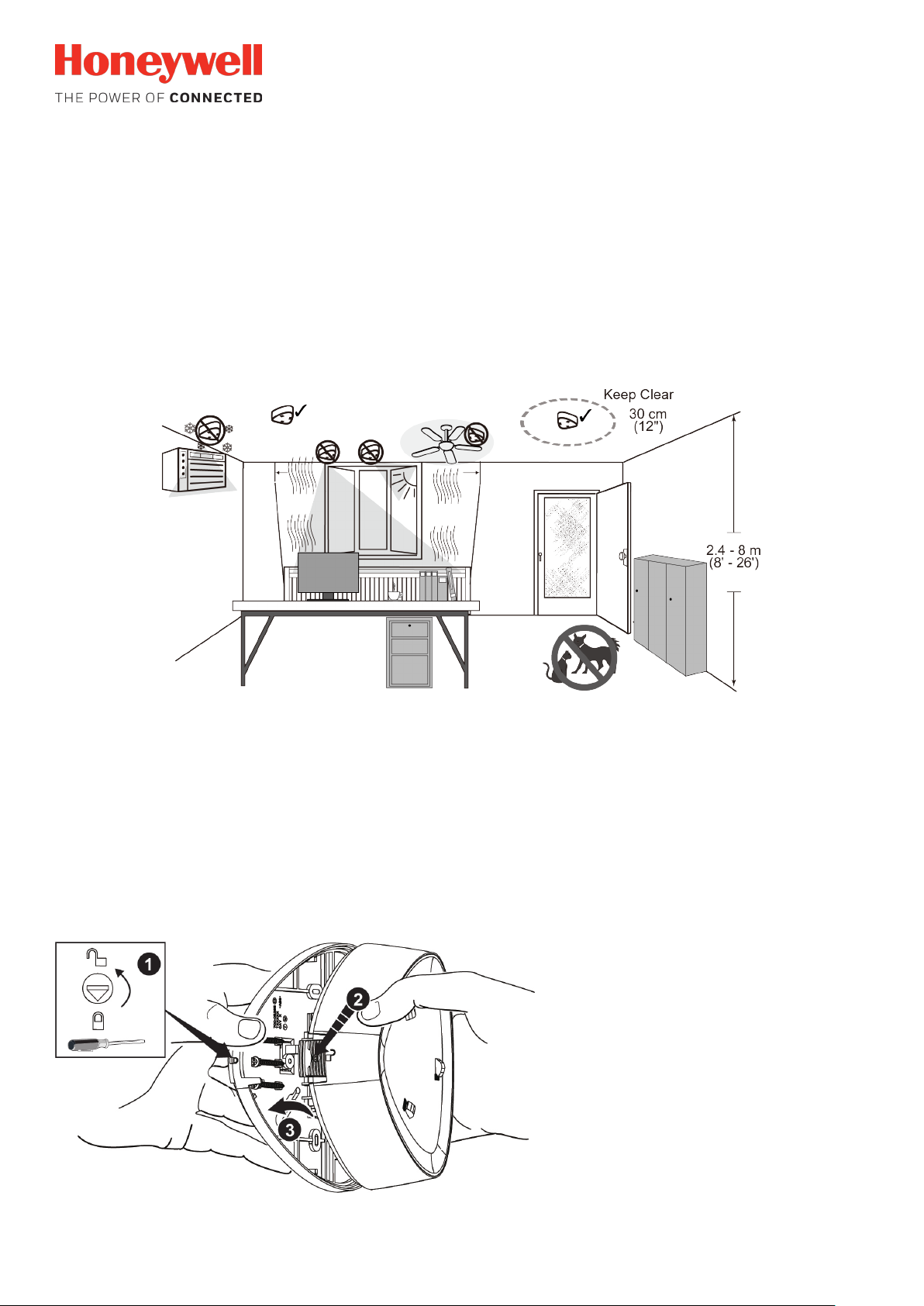
1. Select the Mounting Location
Mounting location guidelines:
• The range is obtained at a mounting height of 2.4m (8’) to 8m (26’). Max. detection range at 8m (26’) is Ø 21m (70’).
• Allow a clear line-of-sight to all areas to protect.
• Avoid mounting anything within 30cm (12”) in front of the sensor.
• Do not directly face windows.
• Avoid close proximity to moving machinery, fluorescent lights, and heating/cooling sources. Avoid use in turbulent air.
• Not for use in applications with pets.
2. Open the Sensor
1. Turn the arrow to point to the Unlock symbol.
2. Press firmly on housing latch.
3. Gently separate the front and rear housing.
- 1 -
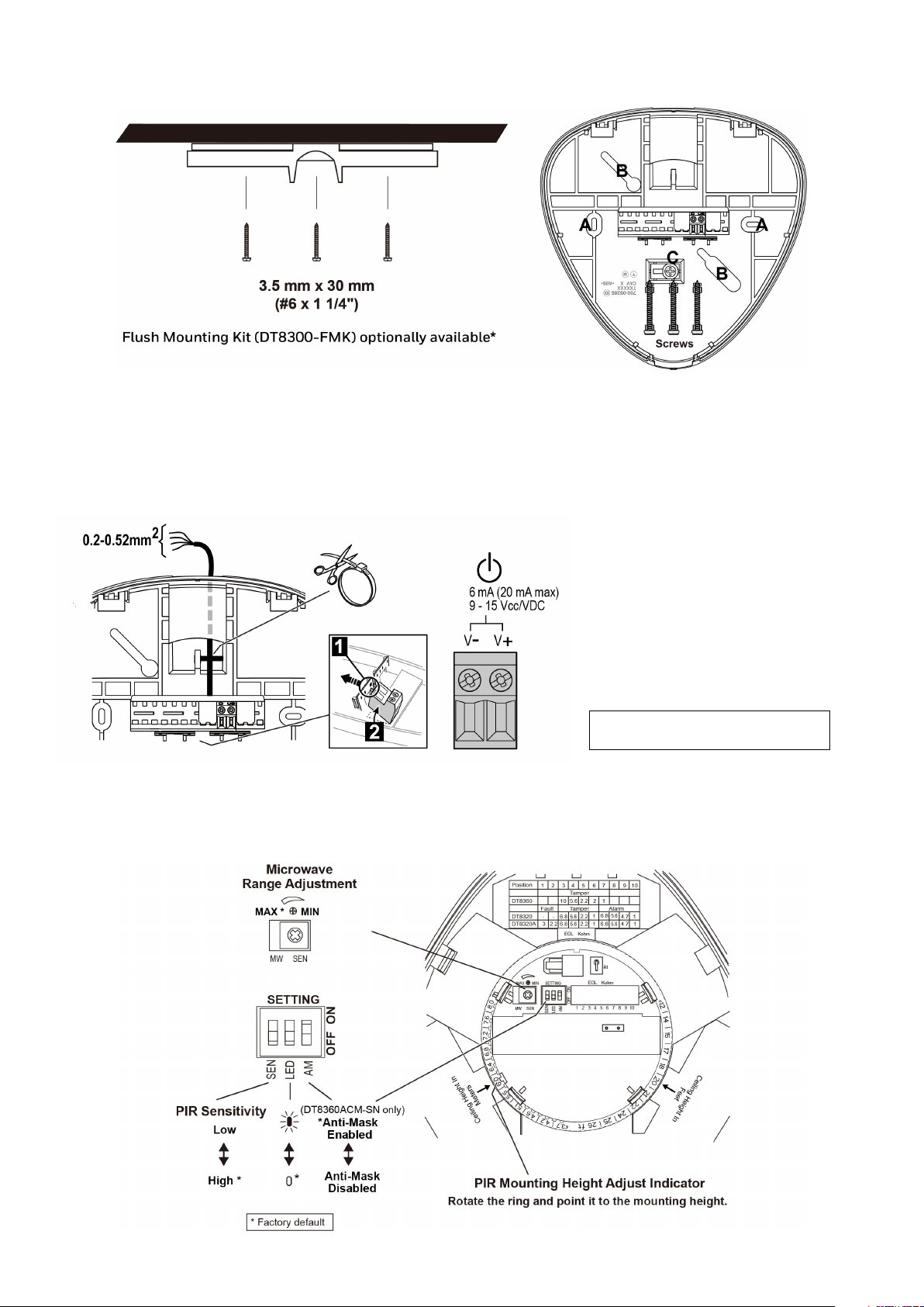
3. Mount the Sensor
Note: Observe proper polarity.
[A] = Fixed mounting holes
[B] = Adjustable mounting slots from 61mm-85mm (2.4”-3.3”)
[C] = Tamper hole
*This accessory is not covered by the approval.
4. Wire the Sensor
For new polling loop installations,
always use shielded twisted pair
wiring. In many cases, existing nontwisted pair wiring may be used, but it
is more susceptible to interference
from other sources, and may be
problematic in installations with long
wire runs or in high noise
environments.
Shielded wiring must be used.
5. Sensor Components and Settings
- 2 -
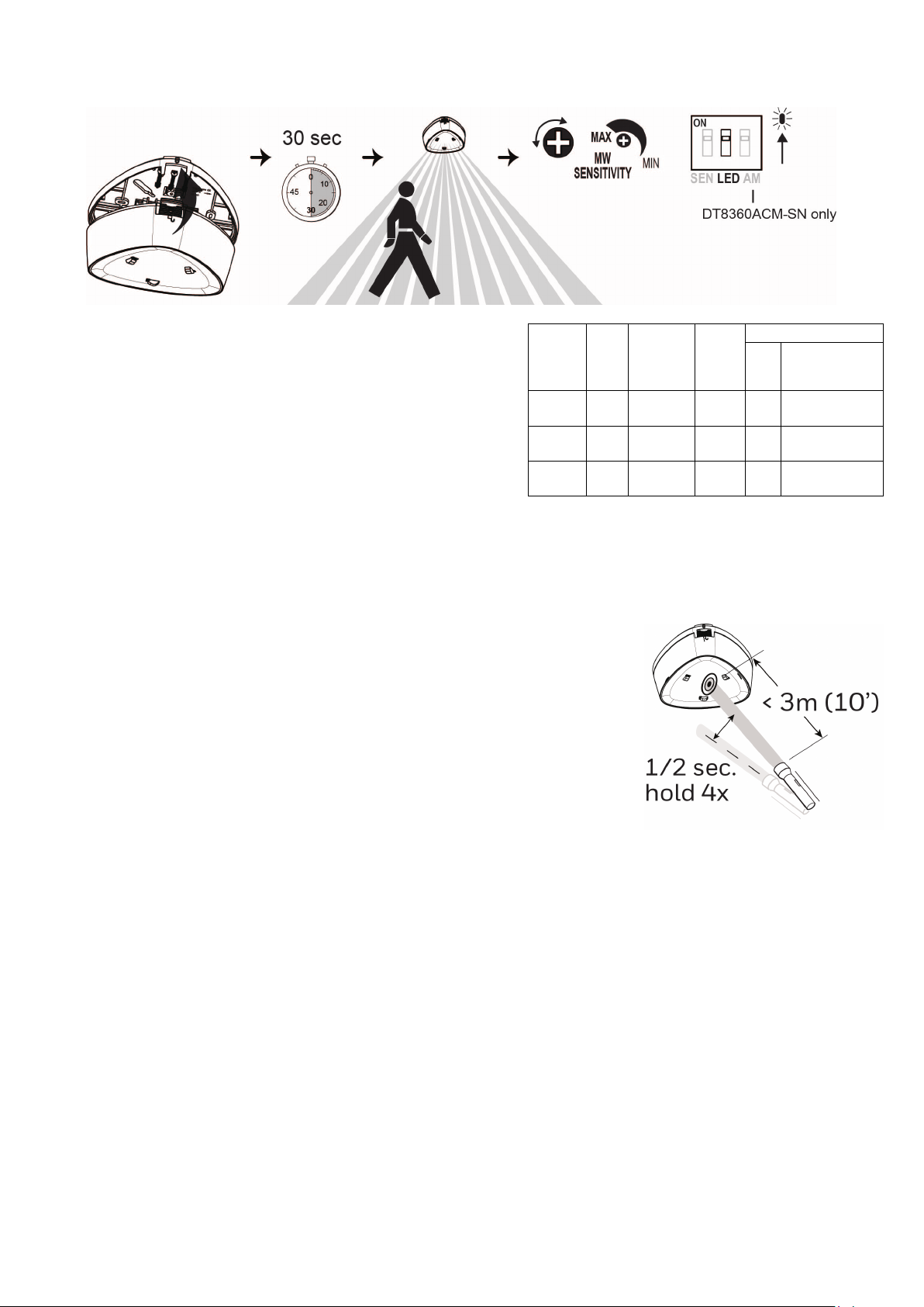
6. Walk Test the Sensor and Adjust as Needed
maximum, the sensor range is Ø 21m (70’).
Power
Trouble
only)
PIR
1. Use a flashlight with a bright light beam, and stand within 3m (10’) of the sensor.
1. Close the sensor and apply power to the sensor. Initialization is
complete when the LED stops flashing slowly (about 30 seconds).
2. Walk through the detection area and observe the LED.
3. Adjust the microwave range as necessary to meet installation
requirements.
Walk test mode is active for 15 minutes, then automatically exits test
mode, disables the LED and enters normal operation mode. For an
additional 15 minute walk test, enable walk test mode again with the
flashlight feature.
Notes:
• During power up and walk test modes the LED is active regardless
of the LED Enable/Disable DIP switch setting.
• When the microwave sensitivity is set to minimum, the sensor range
is reduced to Ø 12m (40’). When the microwave sensitivity is set to
LED
Red
Yellow OFF
Green OFF
Up
Slow
Blink
Walk Test
[15 min.]
ON
Alarm
ON
Microwave
ON
Normal
ON
Alarm
OFF OFF
OFF OFF OFF
Anti-Mask
Fault
(DT8360ACM-SN
Fast
OFF
Blink
Fast
Blink
Flashlight Feature:
2. Swing the light beam past the sensor IR window 3-5 times consistently, holding the
beam on the window for 0.5 second each pass.
Notes:
• The flashlight feature is available for the first 24 hours after power up.
•
The flashlight feature only works with incandescent bulb flashlights. It does not work
with LED flashlights.
- 3 -
 Loading...