

Page 1

❶ Select the mounting location.
❹ Wire the unit.
❸ Mount the unit.
❺a Walk-test the sensor.
Mounting Location Guidelines
• 2.3 m mounting height.
• Avoid direct or reflected sunlight.
• Aim sensor away from windows, heating/cooling devices
or large moving objects.
• Sensor must have a clear line-of-sight to protected area.
• Use a small screwdriver to unfasten the housing latch. Gently pull
apart the housings.
• Push outward on the PCB latch and lift the PCB out of the housing.
• Slide the wire through the wire channel in the back housing.
• Mount the back housing flat against a wall or in a corner.
Note: If using the Rear Tamper feature, refer to the Rear Tamper
section before mounting the sensor.
• Replace the PCB.
• Apply power to the unit. Initialisation is complete when the
LED stops flashing slowly.
• Adjust the microwave range to minimum setting (25%) by
turning the range adjustment counterclockwise using a
small screwdriver.
• Replace the front housing.
• Begin walking through the detection area.
- The LED will turn red, indicating an alarm detection.
• Increase the microwave range as necessary.
• Repeat the items in step 5a until proper detection range is
obtained.
• The sensor MUST be walk tested after every power up
to complete the power up mask detection test.
❺b Optional: Walk-test using Zone Finder.
• Use a screwdriver to short the test pads.
• During the Zone Finder walk-test mode, the LED turns:
- green for one second for every PIR detection;
- yellow for two seconds for every microwave detection.
• Adjust the microwave range as necessary.
• Zone finder mode times out after ten minutes.
Corner
Mount
Holes
Wire Channel
Wall
Mount
Holes
75%
100%
25%
50%
DT7550UK2 DUAL TEC
®
With Anti-Mask Motion Sensor Installation Instructions
Use the Zone Finder mode to identify the PIR and/or
microwave pattern. In Zone Finder mode the red
LED is disabled.
❷ Separate the sensor housings and remove the
printed circuit board (PCB).
Note: The cover screw,
when used, is installed
here.
For improved anti-mask
performance the look-down
mirror is disabled. To enable
look-down remove the mask.
Corner
Mount Hole*
*Note: If the Rear
Tamper function is not
required, do not use the
mounting holes in the
Rear Tamper Breakaway
Tab.
Fault, Alarm and Tamper configured to two loops.
Fault, Alarm and Tamper configured to one loop.
FAULT
(RF)
TAMPER
(RT)
ALARM
(RA)
E
F
A
B
C
D
A
B
C
D
Factory default
settings are
shown in grey.
2.2K
3K
1K
2.2K
4.7K
5.6K
1K
2.2K
4.7K
5.6K
Jumper
Position EOL Value
• Connect wires as shown using 0.2 - 1.3 mm2 wire size.
Observe proper polarity.
• If not using the integrated EOL resistors, remove jumpers from
all pins.
• If using the integrated EOL resistors:
1. Connect the sensor to the panel (see wiring diagrams on
the right; if using the two loop option, also cut link W1).
2. Place the jumpers on the appropriate fault, tamper and
alarm pin options (see table below).
Notes:
• Consult the Control Panel manual to determine proper EOL
selection.
• Fit only one jumper each for the fault, tamper and alarm
EOL settings.
Rear Tamper Breakaway
Tab: Best if mounted to a
stud, solid wood, or with
a robust wall anchor.
Page 2
DT7550UK2 DUAL TEC
®
With Anti-Mask Motion Sensor Product Information
REAR TAMPER
To use this feature:
1. Mark the retaining screw hole location:
For wall/surface mounting, remove the wall mount knockout
and mark the mounting hole location.
For corner mounting, use a sharp, pointed tool to pierce the
thin plastic in the corner mounting hole, and mark the
mounting hole location.
2. Mount the rear housing in the desired location, and use a #6
pan-head screw in the selected Rear Tamper retaining screw
hole.
Important: For best results, mount the sensor housing to a
stud, solid wood, or a robust wall anchor.
Note: If an angled mounting is required, installing the sensor on a
wall using the corner mount holes will only be TS 50131-2-4 compliant if installed
using the Rear Tamper. Alternatively, the SMB-10T mounting bracket can be
used to achieve TS 50131-2-4 compliant angled mounting.
DIP SWITCH SETTINGS (SW1)
Factory default settings are shown in grey.
Switch
1
2
3
OFF
Low Sensitivity
(Pulse Count 2)
LED disabled
Anti-mask Reset 3 Alarm
ON
High Sensitivity
(Pulse Count 1)
LED enabled
Anti-mask Reset 1 Alarm
LED INDICATORS
LED
Red
Yellow
Green
Normal
ON
Alarm
ON
Microwave
ON
PIR
Power Up
Slow
Blink
OFF
OFF
Fault*
Fast
Blink
OFF
OFF
Zone Finder
OFF
ON
Microwave
ON
PIR
OPERATION MODE
*Low Supply Voltage condition does not generate a blinking LED.
Note: LED indicators
work as listed only when
the LED is Enabled
(Switch 2=ON).
RELAY OPERATION
1
For information on Fault conditions, see the Troubleshooting section.
2
In a Mask condition, the Alarm and Fault relays will activate simultaneously,
and remain open until the condition has been cleared.
3
In a Fault condition, the Fault relay will latch open until the Fault condition has
been cleared.
4
To ensure communication clarity, the operation of the Alarm and Fault relays
have been prioritized as follows:
Priority
1 (Highest)
2
3 (Lowest)
Condition Signal
Intrusion Alarm
Fault
Anti-Mask
Note: In situations where multiple
conditions occur at the same time,
the highest priority condition signal
will take precedence after all
conditions present have been
signaled.
© 2008 Honeywell International Inc. • Honeywell, IntelliSense and DUAL TEC are registered trademarks of Honeywell International Inc.
All other trademarks are the properties of their respective owners. All rights reserved. Made in China
800-02416 Rev B
MASK FUNCTION
Power Up Anti-Mask
At power up, the sensor initiates the power up mask detection test. The power up mask test will be completed ONLY
after both the PIR and Microwave technologies are verified by a walk test and an alarm is signaled.
IMPORTANT: The sensor MUST be walk tested after every power up to complete the mask detection
test. If not walk tested, the sensor will remain in power up anti-mask test mode indefinitely, and will
issue a mask signal if a set number of microwave events occur before a PIR event.
Normal Anti-Mask Operation
The sensor signals a mask condition when a variety of materials and reflective objects are placed in front of the
sensor. To avoid false mask alarms, follow the mounting guidelines shown in Step 1.
Clearing an Anti-Mask Condition
Visually inspect the sensor and remove any materials blocking the sensors view. The sensor will clear an anti-mask
condition when detection on both the microwave and PIR resume based on the setting of switch 3. With switch 3 in
the off position, three valid alarm detections will clear the mask condition. With switch 3 in the on position, one valid
alarm detection will clear the mask condition.
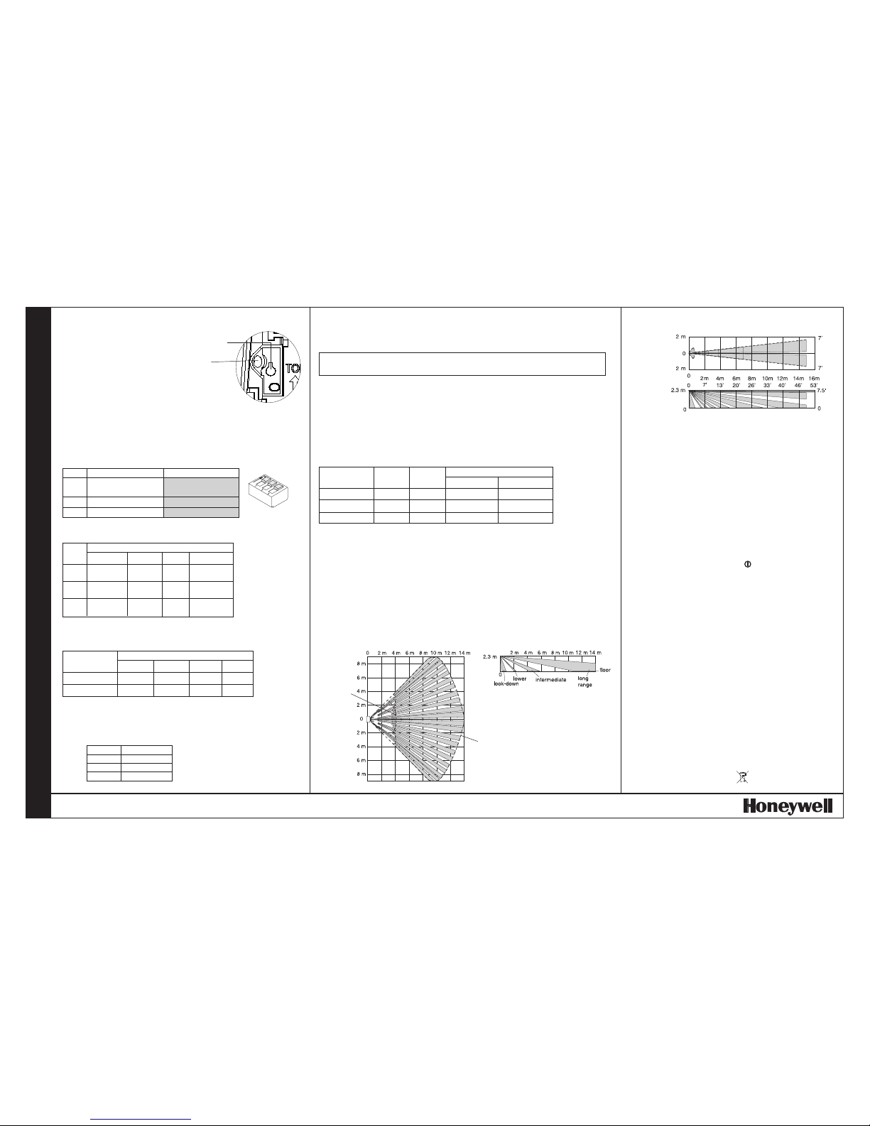
DETECTION PATTERNS
Side View
Minimum
Detection
Pattern
Maximum
Detection
Pattern
Note: Look-down fingers are
enabled only when the look-down
mask is removed (see Step 2).
Top View
Wide Angle
Lens (14 m)
PRODUCT SPECIFICATIONS
Range:
14 m x 18 m
Power requirements:
9.0 - 15.0 VDC; 25 mA typical,
35 mA maximum, 12 VDC
AC Ripple: 3 V peak-to-peak
at nominal 12 VDC
Alarm relay:
Energized Form A
30 mA, 24 VDC,
40 Ohms resistance maximum
Fault relay:
De-energized Form B
(NC) 30 mA, 24 VDC
Tamper switches:
Cover and Wall:
Form A (normally closed with
cover installed)
30 mA, 24 VDC
Microwave frequency:
24.200 GHz
PIR white light immunity:
6,500 Lux typical
Fluorescent light filter:
50 Hz
Operating temperature:
-10o C to +55o C (14o F to +131o F)
5 - 95% relative humidity (noncondensing)
Temperature Compensation:
Advanced dual slope
Trouble:
Microwave Supervision
PIR Self-Test
Temperature Compensation
Low Voltage
PIR fields-of-view:
22 long range
12 intermediate
6 lower
* 4 look-down
Sensitivity:
High (Pulse Count 1) 1 - 2 steps
Low (Pulse Count 2) 3 - 4 steps
Dimensions:
11.9 cm H x 7.1 cm W x 4.2 cm D
Weight:
172 g
Packaged Product: Approx. 211 g
Accessories:
Mounting Brackets --
SMB-10 Swivel Mount Bracket
(P/N 0-000-110-01)
SMB-10C Swivel Mount Ceiling
Bracket (P/N 0-000-111-01)
SMB-10T Swivel Mount Bracket
w/ Tamper (P/N 0-000-155-01)
Curtain Lens (P/N 5-532-820-00)
TS 50131-2-4 Compliant Accessories:
SMB-10T Swivel Mount Bracket
w/ Tamper (P/N 0-000-155-01)
Curtain Lens (P/N 5-532-820-00)
Approvals/listings:
CE
PD6662, EN 50131-1 and TS 50131-2-4
Security Grade 3, Environmental Class II.
Suitable for connection to an EN 60950
Class II Limited Power Source in
European installations.
Note: In TS 50131-2-4 compliant
installations, mount the sensor at
2.3 m, use the Rear Tamper feature,
select the high sensitivity setting, and
install a cover screw (included).
To obtain applicable EU compliance
Declaration of Conformities for this
product, please refer to our Website,
http://www.security.honeywell.com/hsce/
international/index.html. For any
additional information regarding the
compliance of this product to any EU
specific requirements, please contact:
Quality Assurance Department,
Honeywell Security & Custom Electronics,
Newhouse Industrial Estate
Motherwell,
Lanarkshire ML1 5SB,
Scotland,
United Kingdom.
Tel: +44(0)1698 738200
Email: UK64Sales@Honeywell.com
Please contact your local authorised Honeywell
representative for product warranty information.
Alarm Relay
4
Fault Relay
3, 4
Normal
Closed
Closed
Intrusion
Open
Closed
Fault
1
Closed
Open
Mask
2
Open
Open
SENSOR STATUS
Alarm Relay
Fault Relay
Red LED
NORMAL
Closed
Closed
Off
MASK
Open
Open
Off
Low Voltage
1
Closed
Open
Off
Fault
2
Closed
Open
Flashing
FAULT*
*FAULT CONDITIONS:
1
Low Voltage: The sensor is disabled.
2
Three possible conditions:
• Microwave Supervision failure: The sensor is operating in PIR mode only.
• PIR self-test failure: The sensor is disabled.
• Temperature Compensation failure: The temperature compensation is disabled.
Depending on the Fault condition, take the following corrective actions:
• Verify the power supply is sufficient .
• Cycle power to the sensor.
• Walk test the sensor.
• Verify the sensor is not blocked or masked.
If the Fault condition does not clear, replace the sensor.
TROUBLESHOOTING
Side View
Top View
DETECTION PATTERNS (Continued)
Optional Curtain Lens (15 m)
 Loading...