

Page 1
Step 2
Mount the sensor.
Break out the mounting/wiring knockouts and
protect.
mount the sensor in an appropriate location.
An ideal location meets the following objectives:
• Allows a clear line-of-sight to all areas to
fluorescent lights, and heating/cooling
sources.
• Does not directly face windows.
• Avoids close proximity to moving machinery,
containing pets.
• See Special Instructions for installations
NOTE: maximum range is obtained at a
Step 4
Walk-test the sensor.
After returning the PCB to the rear hous-
ing, reassemble the sensor housing. Ap-
ply power to the sensor and begin walk-
mounting height of 2.3 m (7’6”).
test when the red LED is off.
Power
Walk across the detection area at the
ranges to be covered. The red LED should
indicate an alarm condition after 2 to 4 nor-
mal steps. When there is no motion in the
detection area the LED should be off.
TB1
Power
25 mA
7.5-16 VDC
(UL: 8.9-14.5 VDC)
Alarm
30 VDC
500 mA
50 mA
Tamper
24 VDC
TB2
TT
25 mA
7.5-16 VDC
(UL: 8.9-14.5 VDC)
Alarm
30 VDC
500 mA
TB1
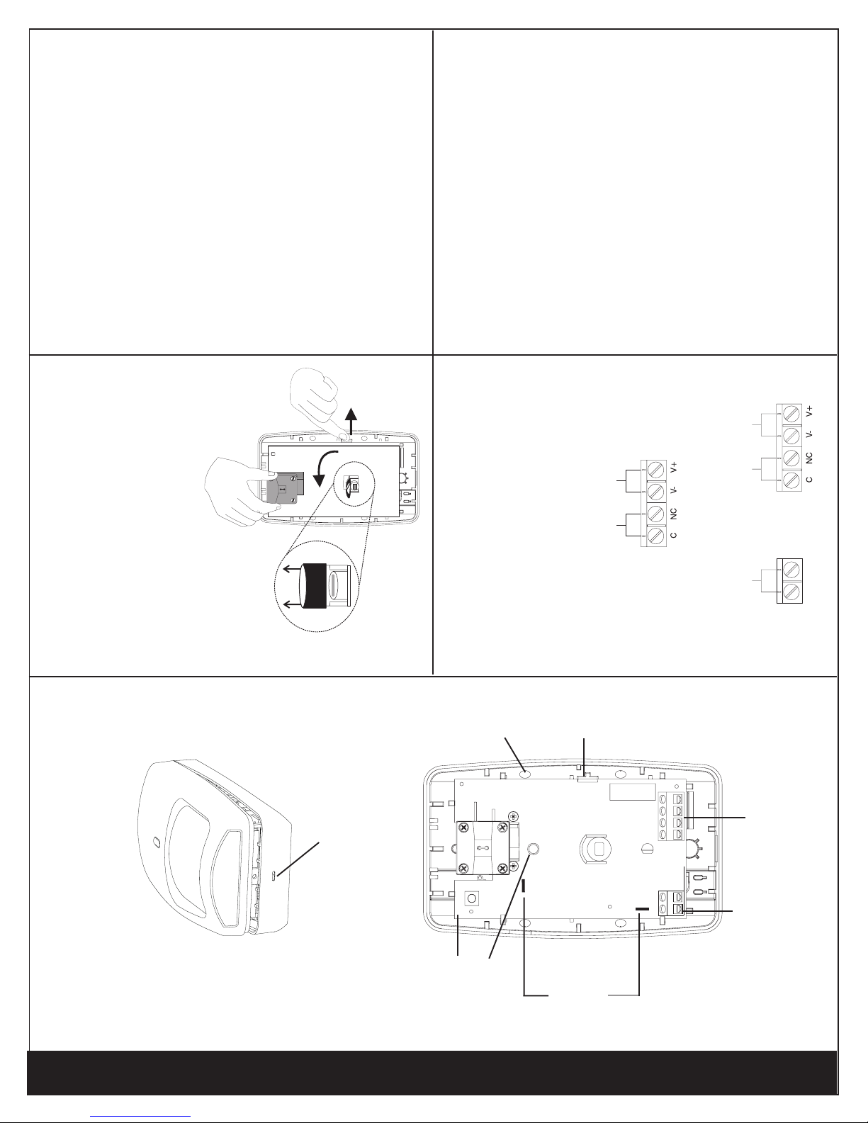
Step 1
Separate the sensor housings and remove
Printed Circuit Board (PCB).
Use a small screwdriver to unfasten the hous-
ing latch and separate the sensor housings.
Push outward on the PCB latch to lift the PCB
out of the housing.
FRONT HOUSING
Housing
latch
Step 3
Remove look-down
mask for non-pet
applications.
REAR HOUSING AND PCB
Wire the sensor.
PCB
LED
Motion Sensor Installation Instructions
®
Observing the proper polarity, wire the unit as
shown in the illustration below, use 1.02 to 0.64 mm
Knockout
(DS1)
DT-7235
(18 to 22 AWG) wire.
PCB latch
LED Enable
(Cut or remove
LED enable jumper
J1* to disable LED)
DT-7235T
Terminal Block (TB1)
TB2
DT-7235T
DT-7235/DT-7235T DUAL TEC
indicated in the above illustration.
* J1 may be located in either location
Page 2

PRODUCT SPECIFICATIONS
Range:
35’ x 40’ (11 m x 12 m)
UL Limits: 35’ x 35’ (11 m x 11 m)
Alarm relay:
Energized Form A
500 mA, 30 VDC
Tamper (DT-7235T):
(NC) 50 mA, 24 VDC
Power requirements:
7.5 - 16 VDC (UL: 8.9-14.5VDC), 25 mA, 0.4W
AC Ripple: 3 V peak-to-peak at nominal 12 VDC
Frequencies:
24.125 GHz
PIR white light immunity:
6,500 Lux typical
RFI immunity:
30 V/m,10 MHz - 1000 MHz
C)
o
to +55
o
F (-10
o
to +131
o
Operating temperature:
+14
5 - 95% relative humidity (non-condensing)
(Indoor use environment)
PIR fields of view:
44 long range edges
36 intermediate edges
18 lower edges
4 down edges
Dimensions:
11.9 cm H x 7.1 cm W x 4.2 cm D
(4.685" H x 2.795" W x 1.654" D)
Sensitivity:
2 - 4 steps within field of view
Accessories:
Optional Lens Kits --
Pet Alley Lens Kit (P/N DT7000-PALK)
Long Range Lens Kit (P/N DT7000-LRLK)
High Security Lens Kit (P/N DT7000-HSLK)
Note: The function of these optional lenses with this
sensor has not been evaluated by Underwriters
Laboratories Inc.
Mounting Brackets --
SMB-10 Swivel Mount Bracket (P/N 0-000-110-01)
SMB-10C Swivel Mount Ceiling Bracket
(P/N 0-000-111-01)
SMB-10T Swivel Mount Bracket w/Tamper
(P/N 0-000-155-01)
Approvals / listings:
FCCICcULus
SPECIAL INSTRUCTIONS FOR INSTALLATIONS CONTAINING PETS
• Mount the center of the detector 7’6” (2.3 m) high.
To take full advantage of the pet immunity the following guidelines should
MICROWAVE SUPERVISION
If the microwave technology stops sending or receiving signals,
the sensor locks into an alarm condition. The LED at the sensor,
however, does not light.
If the microwave regains its signal, the sensor (and LED) returns
to normal operation.
NOTE: The DT-7235/7235T sensors should be tested at least
once each year to ensure proper operation.
DETECTION PATTERNS
DT-7235 / DT-7235T
Pet Immune Lens
11 m (35’)
be followed:
climbing on furniture, boxes or other objects.
• Ensure that the look-down mask is in place (see Step 1).
• Mount where animals cannot come within six feet of the detector by
• Do not aim the detector at stairways that can be climbed by animals.
Notes:
This sensor will provide immunity to false alarms for an individual animal
or a group of animals whose total weight is equal to or less than 45.36 kg
(100 lbs).
The pet immunity function of this sensor has not been evaluated by UL.
Motion Sensor Supplemental Information
Motion Sensor Installation Instructions
®
®
FCC Notice: This equipment has been tested and found to comply with the limits for a Class B digital
device, pursuant to Part 15 of the FCC Rules. These limits are designed to provide reasonable protection
against harmful interference in a residential installation. This equipment generates, uses and can radiate
radio frequency energy and, if not installed and used in accordance with the instructions, may cause
harmful interference to radio communications. However, there is no guarantee that interference will not
occur in a particular installation. If this equipment does cause harmful interference to radio or television
reception, which can be determined by turning the equipment off and on, the user is encouraged to try to
* Look-down fingers are enabled only when look-
down mask is removed, see Step 1.
correct the interference by one or more of the following measures:
• Reorient or relocate the receiving antenna.
• Increase the separation between the equipment and receiver.
• Connect the equipment into an outlet on a circuit different from that to which the receiver is connected.
• Consult the dealer or an experienced radio/TV technician for help.
Changes or modifications to this equipment not expressly approved by Honeywell may void the user’s
authority to operate this equipment.
IC Notice: This apparatus complies with Canadian Standards ICES-003 B and RSS-210.
Canada: Wiring methods shall be in accordance with CSA C22.1, Canadian Electrical Code, Part 1, Safety
Standard for Electrical Installations.
© 2004 Honeywell International Inc. - Honeywell, IntelliSense and DUAL TEC are registered trademarks of Honeywell International Inc.
All other trademarks are the properties of their respective owners. All rights reserved. Made in China
5-051-563-00 Rev J
DT-7235/DT-7235T DUAL TEC
DT-7235/DT-7235T DUAL TEC
 Loading...