

Page 1
DS06D,G
Dial Set Pressure Regulating Valve
FEATURES
• Built-in, factory-calibrated outlet pressure adjustment
dial.
• Noncorroding unitized cartridge contains all working
parts and is easily replaceable.
• Outlet pressure range from 15 to 130 psi in all models,
inlet rating 400 psi.
• Includes built-in strainer and thermal bypass.
• Narrow design to accommodate restricted installation
requirements.
• Balanced seat construction provides superior
pressure regulation.
• Inlet and outlet are internally threaded NPT, and
externally threaded for use with union assemblies.
APPLICATION
• Gauge taps provided on all models.
PRODUCT DATA
The Honeywell DS06D,G Dial Set is a high quality pressure
regulating valve that maintains a constant outlet pressure over
a wide range of inlet supply pressures. It is ideally suited for
potable water and irrigation applications requiring accurate
regulation.
The wide outlet pressure range, high inlet pressure, and
compact design allow flexibility in installation and application.
To facilitate setup and checkout, the DS06D,G features a
calibrated outlet pressure set dial that allows outlet pressure
adjustments without the use of a gauge in most applications.
Contents
Application/Features..........................................................1
Specifications/Ordering Information ..................................2
Installation .........................................................................3
Maintenance and Repair ...................................................4
Operation/Troubleshooting................................................6
DS06D,G Parts and Accessories ...................................... 7
62-3052—1
Page 2
DS06D,G DIAL SET PRESSURE REGULATING VALVE
SPECIFICATIONS
Model: DS06D,G Dial Set Pressure Regulating Valve.
Construction Materials:
Body: Bronze.
Internal Parts: Stainless steel, NBR, and engineered
plastics.
Regulator Mechanism: Fabric reinforced diaphragm.
Thermal Bypass Relief: Integral thermal bypass relief
mechanism on all models.
Seat Design: Balanced single seat.
Inlet Pressure (Maximum): 400 psi.
Reduced Pressure Range: 15 to 130 psi (all models).
Outlet Pressure: Factory set at 60 psi.
Dial Calibration: ±4 psi.
Differential: 14 psi minimum (for optimum regulation).
Reduced Ratio: 10:1 maximum.
Temperature (Maximum): 180° F (82° C).
Ambient Temperature Range: 33° F to 140° F (1° C to
60° C).
Gauge Taps: 1/4 in. NPT (two, one on each side of body).
Weight (With One Union):
1-1/2 in. is 7.7 lb (3.5 kg).
2 in. is 8.5 lb (3.9 kg).
Approvals:
ASSE 1003, City of LA, CSA, IAPMO.
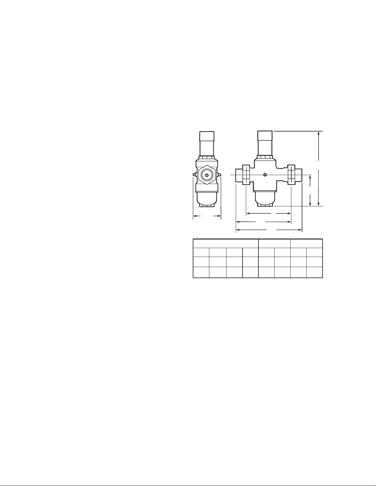
Dimensions: See Fig. 1.
H
h
3.82
(97)
I
L1
L2
Pipe Sizes Available: 1-1/2 and 2 in.
Connections: All models have internal NPT on inlet and
outlet and external union connection on inlet and outlet.
Single and Double Union Sweat and Thread models.
Strainer Screen Size: 0.040 in. (1.0 mm), equivalent to 18
DIMENSIONS IN IN. (MM)
SIZE
1-1/2
H
11-13/16
11-13/16
2
(299)
(299)
(126)
(126)
hI
5
6-3/8
(163)
5
6-3/8
(163)
THREADED
L1
7-13/16
(198)
7-7/8
(200)
9-3/16
(234)
9-5/16
(237)
L2 L1
7-7/8
(201)
8-5/16
(211)
SWEAT
L2
9-3/8
(239)
10-3/16
(259)
M11203
mesh.
Fig. 1. DS06D,G Installation Dimensions in inches (mm).
ORDERING INFORMATION
When purchasing replacement and modernization products from your TRADELINE® wholesaler or distributor, refer to the
TRADELINE
If you have additional questions, need further information, or would like to comment on our products or services, please write or
phone:
1. Your local Honeywell Automation and Control Products Sales Office (check white pages of your phone directory).
2. Honeywell Customer Care
In Canada—Honeywell Limited/Honeywell Limitée, 35 Dynamic Drive, Toronto, Ontario M1V 4Z9.
International Sales and Service Offices in all principal cities of the world. Manufacturing in Australia, Canada, Finland, France,
Germany, Japan, Mexico, Netherlands, Spain, Taiwan, United Kingdom, U.S.A.
®
Catalog or price sheets for complete ordering number.
1885 Douglas Drive North
Minneapolis, Minnesota 55422-4386
62-3052—1 2
Page 3
DS06D,G DIAL SET PRESSURE REGULATING VALVE
Water Capacities (See Table 1)
The suitability of a given regulator size is dependent on the
pressure requirements of each installation. To determine the
pressure regulator valve size required for a specific installation,
calculate the following:
1. Pressure differential between inlet and outlet pressure in
pounds per square inch (psi).
2. Capacity in gallons per minute (gpm), and
3. Allowable reduced pressure falloff in psi.
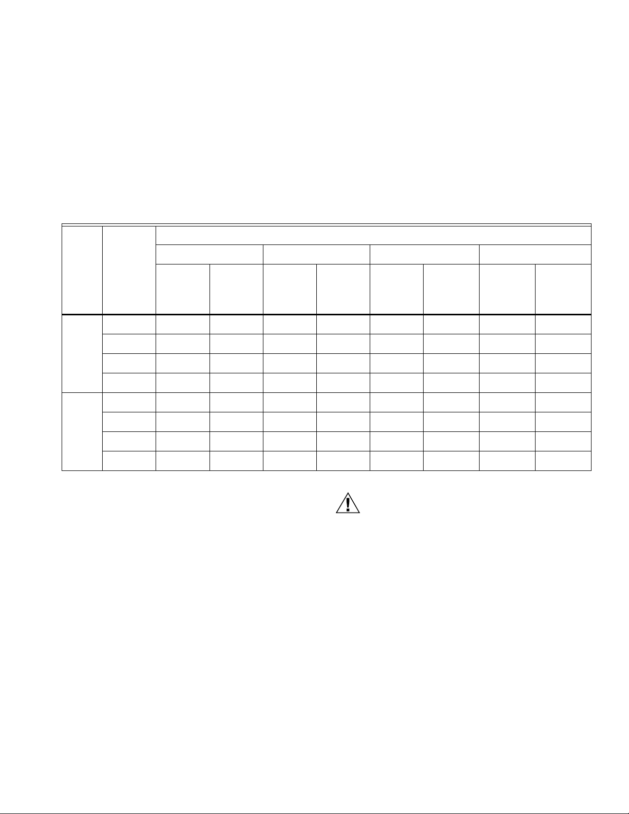
Table 1. Water Capacities.
Pressure Differential Between Inlet and Outlet (psi)—No Flow
25 50 75 100
Reduced
Pressure
Size
(in.)
1-1/2 6 13 2.0 15 2.4 17 2.7 21 3.3
Fall off in
psi
10 36 5.7 43 6.8 46 7.2 54 8.5
15 65 10.2 76 12.0 84 13.2 96 15.1
Flow
Capacity
in US
gpm
Velocity
in ft/sec
Flow
Capacity
in US
gpm
Given these variables, use Table 1 to determine the proper
size pressure regulator valve for your application.
Example: An installation has 135 psi inlet pressure, 60 psi
outlet pressure (75 psi pressure differential). If 30 gpm capacity
is required with only 10 psi falloff allowable, a 1-1/2 in.
DS06D,G is required. This pressure regulator valve allows a
flow capacity up to 46 gpm with a 10 psi falloff at a no flow
pressure differential of 75 psi.
Velocity
in ft/sec
Flow
Capacity
in US
gpm
Vel ocity
in ft/sec
Flow
Capacity
in US
gpm
Veloci ty
in ft/sec
20 88 13.9 102 16.1 114 18.0 132 20.8
2 6 15 1.4 18 1.7 22 2.1 27 2.6
10 41 3.9 49 4.7 57 5.4 66 6.3
15 75 7.2 88 8.4 101 9.7 114 10.9
20 104 9.9 124 11.9 141 13.5 163 15.6
INSTALLATION
CAUTION
When Installing This Product...
1. Read these instructions carefully. Failure to follow them
could damage the product or cause a hazardous
condition.
2. Check the ratings given in these instructions and on the
product to make sure the product is suitable for you
application.
3. Installer must be a trained, experienced service
technician.
4. After installation is complete, check out the product as
provided in these instructions.
Procedure
1. Flush the system clear of sediment and debris.
2. Close the supply valve and downstream isolating valve
(if existing).
3. Install the DS06D,G with the arrow pointing in the
direction of water flow (any mounting orientation is
acceptable). The DS06D,G can be installed directly onto
a pipe using the female NPT threads on each end or by
using single or double unions, if required. (One union is
provided.)
Adjusting Outlet Pressure (See Fig. 2)
The DS06D,G is factory set at 60 psi (no flow). Follow this
procedure if adjustment is required:
Heat from soldering can damage internal parts.
Always remove tailpiece or solder adapter prior to
soldering.
4. Open the supply valve slowly and open the downstream
valve, if provided.
5. Check for leaks at connections and correct, if necessary.
1. Remove dust cap and loosen locking screw one turn
counterclockwise. Do not remove the locking screw.
2. Turn adjusting knob clockwise to increase pressure and
counterclockwise to decrease pressure. When
decreasing pressure, a slight downstream flow is
necessary to relieve pressure. Turn until dial scale
indicates desired pressure (no flow set pressure).
3. Tighten locking screw and replace dust cap.
3 62-3052—1
Page 4

DS06D,G DIAL SET PRESSURE REGULATING VALVE
REMOVE DUST
1
CAP.
2
LOOSEN LOCKING
SCREW ONE TURN,
BUT DO NOT REMOVE
SCREW OR
ADJUSTING KNOB.
INCREASE
TIGHTEN LOCKING
4
SCREW AND REPLACE
DUST CAP.
DECREASE
3
TURN ADJUSTING KNOB
TO INCREASE OR
DECREASE PRESSURE
UNTIL DIAL SCALE
INDICATES DESIRED
PRESSURE.
1
60
2
MAINTENANCE AND REPAIR
Replacing DS06D,G Cartridge
The working parts of the DS06D,G, including diaphragm, valve
seat, strainer, and disk, are all contained in a replaceable
cartridge. To replace the cartridge:
1. Close the supply valve and relieve the downstream
pressure.
2. Remove the dust cap. Relieve pressure on the spring by
loosening the locking screw (do not remove) and turning
the adjusting knob counterclockwise until no resistance
is felt.
3. Remove the bonnet (See Fig. 3) by turning
counterclockwise. Remove the spring and protection
washer (See Fig. 4).
4. Remove the cartridge using two screwdrivers as levers
(See Fig. 4). Remove the cartridge O-ring.
5. Remove the strainer cup (See Fig. 5).
6. Remove the strainer and strainer support. Remove the
U-seal.
7. Clean the inside of the valve and all the components.
NOTE: Replace the U seal (provided in the repair kit) for a
complete cartridge repair.
1
DO NOT REMOVE ADJUSTING KNOB.
SETPOINT READOUT WAS CALIBRATED IN
THE FACTORY AND SET AT 60 PSI. REMOVING
THE ADJUSTING KNOB CANCELS THIS
CALIBRATION – AND REQUIRES RECALIBRATION
USING A PRESSURE GAUGE.
2
MAXIMUM INLET PRESSURE IS 400 PSI. OUTLET
PRESSURE RANGE IS 15 TO 130 PSI.
Fig. 2. Adjusting Outlet Pressure
REMOVE BONNET USING
60
MT06A SERVICE TOOL
(ORDERED SEPARATELY) TO
TURN COUNTERCLOCKWISE.
60
M11209
8. Replace the U-seal by placing the U-seal on the strainer
support and pushing the assembly into place. The U-seal
open end must face the strainer support (See Fig. 7).
Replace the strainer onto the strainer support.
9. Assemble the strainer cup O-ring onto the strainer cup
and insert the assembly into the body of the valve.
Tighten securely using the service tool. Do not over
torque.
10. Replace the new cartridge ensuring the O-ring is in
place.
11. Replace the protection washer with the lip up (away from
the valve body). See Fig. 6.
12. Replace the spring and bonnet. Tighten the bonnet using
the service tool. Do not over torque.
13. Adjust the outlet pressure following the procedure in
Adjusting the Outlet Pressure section.
REMOVE SPRING
AND PROTECTION
WASHER.
REMOVE CARTRIDGE USING
TWO SCREWDRIVERS
AS LEVERS.
M11210
Fig. 3. Removing Bonnet.
62-3052—1 4
M11212
Fig. 4. Removing Cartridge.
Page 5

DS06D,G DIAL SET PRESSURE REGULATING VALVE
60
REMOVE STRAINER CUP USING
MT06A SERVICE TOOL.
M11211
Fig. 5. Removing Strainer Cup.
DUST CAP
BONNET
ASSEMBLY
SPRING
PROTECTION WASHER
CARTRIDGE
CARTRIDGE O-RING
Fig. 6. Replacing Protection Washer.
TAILPIECE
GASKET
U-SEAL
STRAINER SUPPORT
STRAINER
STRAINER
CUP O-RING
STRAINER CUP
Fig. 7. Internal Parts.
UNION
NUT
M11207
5 62-3052—1
Page 6

DS06D,G DIAL SET PRESSURE REGULATING VALVE
Cleaning Strainer Screen
To clean the strainer screen:
1. Close the supply valve and relieve the downstream
pressure.
2. Remove the strainer cup (See Fig. 5).
3. Remove the strainer and the strainer support. Do not
remove the U-seal.
4. Clean the strainer cup and the strainer.
5. Replace the strainer on the strainer support. Insert the
assembly into the valve.
6. Assemble the strainer cup O-ring onto the strainer cup
and insert the assembly into the body of the valve.
Tighten securely using the service tool. Do not over
torque.
Recalibrating DS06D,G
If the adjusting knob and dial are accidentally removed, the dial
must be recalibrated as follows:
1. Follow the procedure in Adjusting the Outlet Pressure
section. Set the pressure on the gauge at 60 psi (or
another convenient pressure).
2. Reassemble the dial ring onto the bonnet with the
pressure on the ring matching the pressure gauge.
3. Assemble the locking screw and tighten. Replace the
dust cap.
OPERATION
The Honeywell DS06D,G Dial Set is a balanced, direct acting
pressure-regulating valve. It provides constant downstream
pressure regardless of varying inlet pressures and downstream
flow demands.
The spring force holds the valve in the open position until
downstream pressure, sensed by a port, is sufficient to press
on the underside of the diaphragm and close the valve. As
downstream pressure drops due to demand, the force on the
diaphragm is reduced and the valve opens. Adjustment is
made by manually turning the adjustment knob clockwise to
increase the spring force and require a higher downstream
pressure to close the valve. Similarly, reducing the spring force
lowers the outlet set pressure. A factory-calibrated dial is built
into the adjustment mechanism to allow outlet pressure (under
no flow condition) to be set without a gauge. A lock screw
maintains the setting. A black plastic cover is provided for
additional protection.
When the outlet pressure is set, the DS06D,G automatically
regulates to maintain the downstream pressure.
TROUBLESHOOTING
Table 2 is a troubleshooting guide for the DS06D,G Pressure
Regulating Valves.
Table 2. Troubleshooting DS06D,G Pressure Regulating Valves.
Problem Cause Solution
Will not hold pressure or pressure
gradually rises.
Frozen. Valve exposed to freezing temperatures
Pressure gauge measures a lower
pressure under flow conditions than set
pressure at no flow.
Low capacity, low outlet pressure. Screen blocked with debris.
Thermal expansion.
Debris on valve seat.
Damaged valve seat.
below 32° F (0° C).
This is normal and characteristic of
direct-acting pressure-reducing valves.
Valve undersized.
Install a thermal expansion tank to limit
pressure rise.
Clean valve.
Replace cartridge.
Inspect and replace any damaged
components. Move valve to a location
that remains above freezing.
No action is necessary.
Clean screen.
Check capacity versus requirements
and increase valve size.
62-3052—1 6
Page 7

DS06D,G PARTS AND ACCESSORIES
Product Number Description
Replacement Parts
K06B1030 Strainer Kit for D06G and DS06G, 1-1/2 in.
and 2 in., includes strainer, strainer support,
and strainer cup O-ring.
K06D1044 Cartridge Kit for all D06 and DS06, 1-1/2 in.
and 2 in., includes cartridge, cartridge Oring, strainer cup O-ring, U-seal, and
protection washer.
272852 Strainer Cup for D06G and DS06D,G, 1-1/2
in. and 2 in., includes plastic strainer cup
and strainer cup O-ring.
272867 Bonnet kit for D06G, 1-1/2 in. and 2 in.,
includes preassembled bonnet, protection
washer, and spring.
Union Kits
DS06D,G DIAL SET PRESSURE REGULATING VALVE
K06U5034 Union Kit Sweat, 1-1/2 in., includes sweat
tailpiece, union nut, and gasket, and fits all
1-1/2 in. D06 and DS06 Valves.
K06U5042 Union Kit Sweat, 2 in., includes sweat
tailpiece, union nut, and gasket, and fits all 2
in. D06 and DS06 Valves.
7 62-3052—1
Page 8

DS06D,G DIAL SET PRESSURE REGULATING VALVE
Automation and Control Solutions
Honeywell International Inc. Honeywell Limited-Honeywell Limitée
1985 Douglas Drive North 35 Dynamic Drive
Golden Valley, MN 55422 Toronto, Ontario M1V 4Z9
customer.honeywell.com
® U.S. Registered Trademark
© 2006 Honeywell International Inc.
62-3052—1 J.I. Rev. 11-06
 Loading...