

Honeywell DS06-100-SUS-LF, DS06-101-SUS-LF, DS06-102-SUS-LF, DS06-103-SUS-LF, DS06-104-SUS-LF Installation Manual
...Page 1

33-00014EF-07
DS06 Low Lead Content
Dial Set Pressure Regulating
Valves
INSTALLATION INSTRUCTIONS
APPLICATION
The Honeywell DS06 Dial Set® Pressure Regulating
Valve is a high quality pressure regulating valve that
maintains a constant outlet pressure over a wide
range of inlet supply pressures. It is suitable for
potable water and irrigation applications. The
downstream pressure adjustment dial eliminates the
need for a pressure gauge when adjusting the
pressure setting (static pressure only).
SPECIFICATIONS
Model: DS06 Dial Set Pressure Regulating Valves.
Construction Materials:
Body: Brass.
Internal Parts: Stainless steel and engineered
plastics.
Regulator Mechanism: Fabric-reinforced diaphragm.
Seat Design: Balanced single seat construction.
Inlet Pressure (Maximum): 250 psi maximum.
Reduced Pressure Range:
25 to 90 psi (1/2 in. to 2 in.).
Outlet Pressure: Factory set at 60 psi (414 kPa).
Dial Calibration: ± 4 psi.
Differential: 14.5 psi minimum (inlet to outlet).
Fluid Temperature (Maximum):
Water: 140° F (60° C).
Ambient Temperature Range: 33° F to 140° F (1° C
to 60° C).
Pipe Sizes Available: 1/2 in., 3/4 in., 1 in., 1-1/4 in.,
1-1/2 in. and 2 in. available.
Connections:
Can be configured as female thread-by-thread,
single- or double-union, NPT threaded or sweat.
Low Lead Content: < 0.25% Lead.
Gauge Tap: 1/4" NPT.
Approvals:
ASSE 1003 Listed
CSA Certified
IAPMO/UPC Listed
NSF 61 Compliant
INSTALLATION
When Installing this Product...
1. Read these instructions carefully. Failure to
follow them could damage the product or cause
a hazardous condition.
2. Check the ratings given in these instructions
and on the product to make sure the product is
suitable for your application.
3. Installer must be a trained, experienced service
technician.
4. After installation is complete, check out the
product operation as provided in these
instructions.
Page 2
DS06 LOW LEAD CONTENT DIAL SET PRESSURE REGULATING VALVES
Water Capacities
The suitability of a given regulator size is dependent
on the pressure requirements where it will operate. For
the pressure regulator valve size required for a specific
installation, determine the following:
1. Pressure differential between inlet and outlet
pressure in pounds per square inch (psi),
2. Capacity in gallons per minute, and
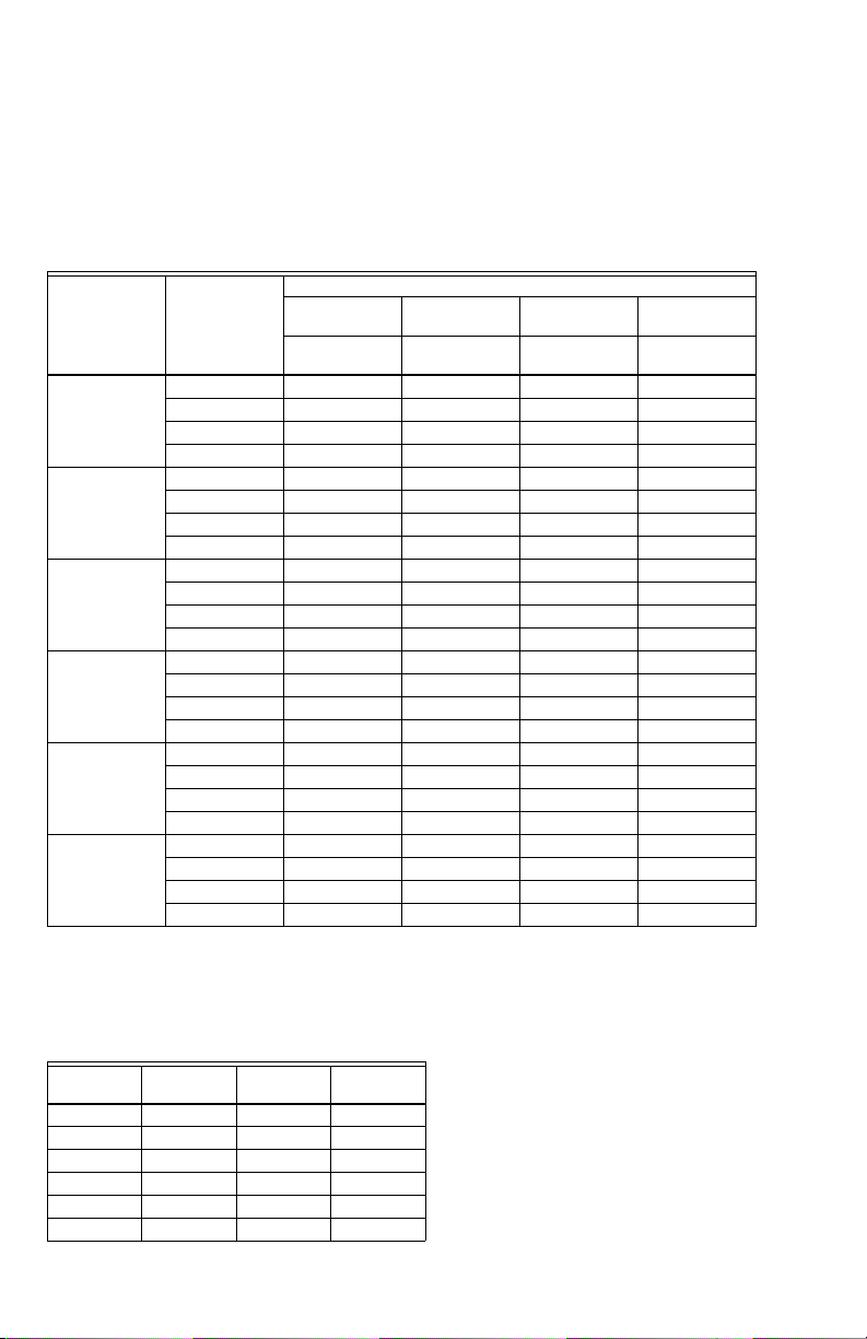
Table 1. Water Capacities.
Pressure Differential Between Inlet and Outlet
Pressure
Regulator
Valve Siz e
1/2" 6 7.26 8.15 7.44 6.47
3/4" 6 11.98 14.44 14.53 14.97
1" 6 11.18 11.23 9.51 9.11
1-1/4" 6 7.53 6.34 7.26 7.13
1-1/2" 6 29.81 32.27 30.87 26.81
2" 6 27.34 25.8 24.48 18.01
Reduced
Pressure
Falloff (PSI)
10 10.7 10.66 9.69 8.85
15 14.27 15.72 14.49 13.96
20 17.74 19.59 18.98 18.1
10 17.17 21.05 25.23 26.33
15 19.86 25.14 29.32 32.85
20 21.27 26.42 30.42 33.82
10 18.01 18.98 17.39 16.78
15 25.67 28.14 28.71 26.9
20 30.69 34.7 36.19 35.05
10 20.25 17.88 15.15 14
15 33.02 34.87 32.63 29.68
20 40.07 44.29 46.01 34.61
10 46.14 50.02 49.89 47.82
15 66.22 78.42 86.74 84.14
20 77.14 92.29 103.82 109.68
10 64.81 97.61 78.15 90.09
15 82.82 105.14 119.94 129.62
20 87.66 107.83 120.95 132.09
25 psi 50 psi 75 psi
Flow Capacity
(US gpm)
3. Allowable reduced pressure falloff in psi. Given
these variables, use Table 1 to determine the
proper size pressure regulator valve for your
application.
Example: An installation has 135 psi inlet pressure,
60 psi outlet pressure (75 psi pressure differential). If
a 15 gpm capacity is required with only 10 psi falloff
allowable, a 3/4 in. DS06 is required.
Flow Capacity
(US gpm)
Flow Capacity
(US gpm)
Flow Capacity
100 psi or
more
(US gpm)
DSO6 Fixture Unit
Flow rates based on submittal sheet DS06, based on
flush tank systems with a 15 psi fall-off defined by
IAPMO/ANSI UPC 1-2009.
Table 2.
Size I/s GPM
1/2” 0.99 15.72 21
3/4” 1.58 25.14 40
1” 1.77 28.14 48
1-1/4” 2.19 34.87 70
1-1/2” 4.93 78.42 270
2” 6.61 105.14 400
33-00014EF—07 2
Fixture
Units
Capacities are based on a 100 psi supply pressure and
a difference of 50 psi or more between the initial
supply pressure and the reduced no-flow pressure.
Check local water pressures before selection.
Procedure
1. Flush the system clear of sediment or debris.
2. Close the supply valve and downstream isolating
valve (if one is installed).
3. Install the DS06 with the arrow on the body
pointing in the direction of water flow. Install,
preferably, in horizontal pipework with filter bowl
downwards - vertical installation also possible.
The DS06 can be installed directly onto the pipe by
using the female NPT threads on each end. If space
limitations restrict turning the DS06, install single- or
double-unions.
Page 3
DS06 LOW LEAD CONTENT DIAL SET PRESSURE REGULATING VALVES
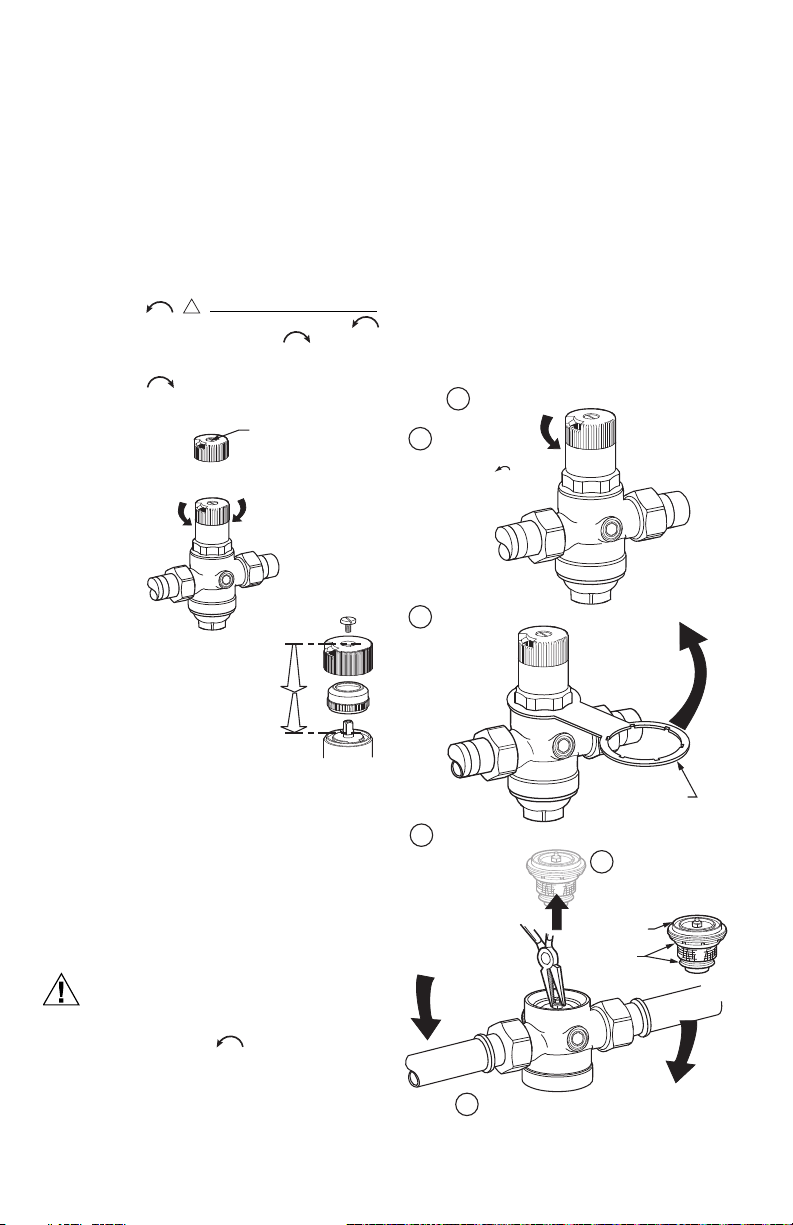
CAUTION
!
LOOSEN LOCKING
SCREW ONE TURN
ADJUST SETPOINT AT THE DESIRED VALUE BY ACTUATING SELECTOR.
INLET PRESSURE (MAXIMUM): 250 PSI
REDUCED PRESSURE RANGE:
25 TO 90PSI 1/2 IN. TO 2 IN. SIZE
NOTE: DO NOT DISMANTLE KNOB
SET-POINT READOUT HAS BEEN CALIBRATED
IN THE FACTORY AND SET AT 60 PSI.
DISMANTLING THE SELECTOR KNOB WILL
CANCEL THIS CALIBRATION. RECALIBRATE
USING A PRESSURE GAUGE. SEE RECALIBRATION.
M35046A
3
M35634A
1
4
6
2
LOOSEN THE SETPOINT DIAL LOCKING SCREW.
UNSTRESS THE
PRESSURE SPRING
BY TURNING COUNTERCLOCKWISE .
UNSCREW THE BONNET WITH A 1-5/8" WRENCH.
REMOVE CARTRIDGE USING A PLIERS AS A LEVER.
REASSEMBLE BONNET IN REVERSE ORDER.
1-5/8" WRENCH
O-RINGS
WASHER
(LIP UP)
5
WHEN REASSEMBLING,
ENSURE O-RINGS AND
WASHER ARE PROPERLY
INSTALLED
NOTE: Heat from soldering can damage internal
parts of the DS06. Always solder the tailpieces
separately from the DS06.
4. Open the supply valve slowly and check for
leakage and proper operation of the DS06.
Changing the Downstream Pressure (See Fig. 1)
Remove the dust cap from the DS06. The DS06 is
factory set to 60 psi.
To adjust the outlet pressure to a desired setting:
1. Loosen the locking screw by turning counter-
clockwise (Do not remove this screw.)
2. Turn the adjusting knob counter-clockwise
to reduce pressure or clockwise to
increase pressure.
3. Lock the setting by turning the locking screw
clockwise .
4. Replace the dust cap over the dial.
8. Remove cartridge using a pliers as a lever.
9. Reassemble bonnet in reverse order.
Recalibrate
If the dial knob assembly has been disassembled
recalibration is necessary.
1. Close shutoff valve on inlet.
2. Release pressure on outlet side (e.g. through
water tap).
3. Close shutoff valve on outlet.
4. Remove dust cap.
5. Loosen slotted screw (do not remove screw).
6. Fit pressure gauge.
7. Slowly open shutoff valve on inlet.
8. Set desired outlet pressure (e.g. 60 psi).
9. Align scale (e.g. 60 psi) in middle of viewing win-
dow.
10. Retighten slotted screw.
11. Slowly open shutoff valve on outlet.
Fig. 1. Changing outlet pressure.
Replacing the Cartridge (Fig. 2)
The working parts of the DS06, including diaphragm,
valve seat, strainer, and disk are all contained in a
replaceable cartridge. To replace the cartridge:
1. Close shutoff valve on inlet.
2. Release pressure on outlet side (e.g. through
water tap).
3. Close shutoff valve on outlet.
4. Loosen slotted screw (do not remove the screw).
To prevent injury and/or equipment damage,
loosen locknut and turn adjusting screw
counter-clockwise to remove spring
tension.
5. Slacken tension in compression spring by
turning counter clockwise until it does not move
anymore.
6. Unscrew Bonnet.
7. Remove slip ring.
Fig. 2. Replacing the DS06 cartridge.
3 33-00014EF—07
Page 4
DS06 LOW LEAD CONTENT DIAL SET PRESSURE REGULATING VALVES
Cleaning
1. Close shutoff valve on inlet.
2. Release pressure on outlet (e.g. through water
tap).
3. Close shutoff valve on outlet.
4. Unscrew filter bowl using a 1-5/8" wrench.
5. Remove filter, clean and reinsert.
6. Place O-ring onto filter bowl.
7. Screw in filter cup hand-tight.
8. Slowly open shutoff valve on inlet.
9. Slowly open shutoff valve on outlets.
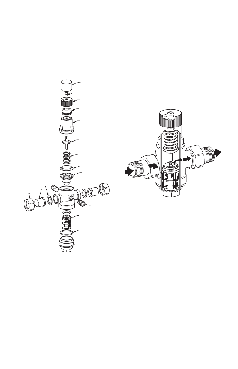
DUST CAP
(BLACK)
LOCKING SCREW
ADJUSTING
KNOB
DIAL RING
BONNET
SPINDLE
SPRING
WASHER
CARTRIDGE
GASKETS (2)
TAILPIECES (2)
NUTS
(2)
PLUGS (2)
REPLACEMENT
FILTER
OPERATION
DS06 is a spring loaded pressure reducing valve that
operates by means of force equalizing system. The
force of a diaphragm operates against the force of an
adjustment spring. If the outlet pressure and therefore
diaphragm force fall because water is dawn, the then
greater force of the spring causes the valve to open.
The outlet pressure then increases until the forces
between the diaphragm and the spring are equal
again. The inlet pressure has no influence in either
opening or closing the valve. Because of this, inlet
pressure fluctuation does not influence the outlet
pressure, thus providing inlet pressure balancing. See
Fig. 4 for the internal construction of the DS06.
NOTE: Minimum ambient rating is 33° F (1° C).
4
M35052
Fig. 4. Internal construction of DS06.
O-RING SET
FOR DO6F
M35053A
Fig. 3. DS06 exploded view.
33-00014EF—07 4
Page 5

DS06 LOW LEAD CONTENT DIAL SET PRESSURE REGULATING VALVES
TROUBLESHOOTING
Table 3 provides a troubleshooting guide for the DS06 Dial Set Pressure Regulating Valve.
Table 3. Troubleshooting the DS06 Dial Set Pressure Regulating Valve.
Problem Cause Remedy
Beating Sounds. Pressure reducing valve is too large. Refer to capacities table to find correct
Water is escaping from the
spring bonnet.
Too little or no water pressure. Shutoff valves up- or downstream of
The outlet pressure set does
not remain constant.
Diaphragm in valve insert is faulty. Replace valve insert.
the pressure reducing valve are not
fully open.
Pressure reducing valve is not set to
the desired outlet pressure.
Filter in pressure reducing valve is
contaminated.
Pressure reducing valve is not fitted in
flow direction.
Filter in pressure reducing valve is
contaminated or worn.
Valve insert, sealing ring or edge of
nozzle is contaminated or worn.
Rising pressure on outlet (e.g. in
boiler).
valve size.
Open the shutoff valves fully.
Set outlet pressure.
Clean or replace filter.
Fit pressure reducing valve in flow
direction. (Note direction of arrow on
housing.)
Clean or replace filter.
Replace valve insert.
Check check valve, safety group etc.
5 33-00014EF—07
Page 6

DS06 LOW LEAD CONTENT DIAL SET PRESSURE REGULATING VALVES
A
DS06 LOW-LEAD REPLACEMENT PARTS
Table 4. Replacement Parts.
Number Part# Sizes Part Description
1 D06FA-1/2 1/2" & 3/4" Valve Insert
D06FA-1B 1" & 1-1/4"
D06FA-1 1/2 1-1/2" & 2"
2 ES06F-1/2A 1/2" & 3/4" Replacement Filter
ES06F-1B 1" & 1-1/4"
ES06F-1 1/2A 1-1/2" & 2"
3 SB06T-1/2 1/2" & 3/4" Black Filter Bowl
SB06T-1 1" & 1-1/4"
SB06T-1 1/2 1-1/2" & 2"
Complete without
Filter
Insert
with O-Ring
1
2
DS06 LOW-LEAD ACCESSORY
Table 5. Accessories.
Part # Size Part Description
K06U1069/U 1/2" Union kit for 1/2-in. NPT
K06U1077/U 3/4" Union kit for 3/4-in. NPT
K06U1085/U 1" Union kit for 1-in. NPT valves.
K06U1135/U 1-1/4" Union kit for 1-1/4-in. NPT
K06U1037/U 1-1/2" Union kit for 1-1/2-in. NPT
K06U1045/U 2" Union kit for 2-in. NPT valves.
K06U1093/U 1/2" Union kit for 1/2-in. sweat
K06U1101/U 3/4" Union kit for 3/4-in. sweat
K06U1119/U 1" Union kit for 1-in. sweat
K06U1143/U 1-1/4" Union kit for 1-1/4-in. sweat
K06U5034/U 1-1/2" Union kit for 1-1/2-in. sweat
K06U5042/U 2" Union kit for 2-in. sweat
valves. Includes union nut,
threaded tailpiece, and gasket
valves. Includes union nut,
threaded tailpiece, and gasket
Includes union nut, threaded
tailpiece, and gasket
valves. Includes union nut,
threaded tailpiece, and gasket
valves. Includes union nut,
threaded tailpiece, and gasket
Includes union nut, threaded
tailpiece, and gasket
valves. Includes union nut,
sweat tailpiece, and gasket
valves. Includes union nut,
sweat tailpiece, and gasket
valves. Includes union nut,
sweat tailpiece, and gasket
valves. Includes union nut,
sweat tailpiece, and gasket
valves. Includes union nut,
sweat tailpiece, and gasket
valves. Includes union nut,
sweat tailpiece, and gasket
3
M35570
Fig. 5. Replacement Parts.
By using this Honeywell literature, you agree that Honeywell will have no liability for any damages arising out of
your use or modification to, the literature. You will defend and indemnify Honeywell, its affiliates and subsidiaries,
from and against any liability, cost, or damages, including attorneys’ fees, arising out of, or resulting from, any
modification to the literature by you.
Home and Building Technologies
In the U.S.:
Honeywell
1985 Douglas Drive North
Golden Valley, MN 55422-3992
customer.honeywell.com
® U.S. Registered Trademark
© 2017 Honeywell International Inc.
33-00014EF—07 M.S. Rev. 03-17
Printed in United States
Page 7

33-00014EF-07
Régulateurs de pression Dial
Set à faible teneur en plomb
DS06
NOTICE D'INSTALLATION
APPLICATION
Le régulateur de pression Dial Set® DS06 de
Honeywell est un régulateur de pression de qualité
supérieure maintenant une pression de sortie
constante sur une large plage de pressions d'entrée. Il
est adapté aux applications à l'eau potable et
d'irrigation. Le cadran de réglage de pression
descendante élimine le besoin d'un manomètre lors
de l'ajustement de la pression (pression statique
uniquement).
CARACTÉRISTIQUES
Modèle : Régulateurs de pression Dial Set DS06.
Matériaux de construction :
Corps : laiton.
Pièces internes : Acier inoxydable et plastiques
techniques.
Mécanisme de régulation : Membrane renforcée de
tissu.
Conception du siège : Construction à siège unique
équilibré.
Pression d'entrée (maximum) : 250 psi maximum.
Plage de pression réduite :
25 à 90 psi (1/2 po à 2 po).
Pression de sortie : Réglée en usine à 60 psi
(414 kPa).
Étalonnage du cadran : ± 4 psi.
Pression différentielle : 14,5 psi minimum
(entrée à sortie).
Température de fluide (maximum) :
Eau : 60°C (140°F).
Plage de température ambiante : 1°C à 60°C (33°F
à 140°F).
Tailles de conduits disponibles : 1/2 po, 3/4 po,
1 po, 1-1/4 po, 1-1/2 po et 2 po disponibles.
Connexions :
Peut être configuré avec filetage femelle, raccord
simple ou double, à filetage NPT ou à souder.
Faible teneur en plomb : < 0,25 % de plomb.
Prise de manomètre : 1/4 po NPT.
Homologations :
Répertorié ASSE 1003
Certification CSA
Répertorié IAPMO/UPC
Conformité NSF 61
INSTALLATION
Lors de l'installation du produit...
1. Lire attentivement ces instructions. Le non-
respect des instructions peut endommager le
produit ou provoquer une situation dangereuse.
2. Vérifier les caractéristiques nominales
indiquées dans cette notice et sur le produit
pour s'assurer que le produit correspond bien à
l'application prévue.
3. L'installateur doit être un technicien
expérimenté ayant reçu la formation adéquate.
4. Une fois l'installation terminée, vérifier que le
produit fonctionne comme indiqué dans cette
notice.
Capacités en eau
L'applicabilité d'une taille de régulateur donnée
dépend des exigences de pression de l'application.
Pour obtenir la taille du régulateur requise pour une
installation spécifique, il faut déterminer les points
suivants :
1. Pression différentielle entre l'entrée et la sortie
en psi (lb/po2),
2. Capacité en gallons par minute, et
3. Affaiblissement de pression réduite permis en
psi. En fonction de ces variables, utiliser le Tableau 1 pour déterminer la taille du régulateur de
pression correspondant à l'application.
Exemple : Une installation comporte une pression
d'entrée de 135 psi, une pression de sortie de 60 psi
(différentiel de 75 psi). Si une capacité de 15 gal./min
est requise avec un affaiblissement permis de 10 psi
uniquement, un régulateur DS06 de 3/4 po est
requis.
Page 8

RÉGULATEURS DE PRESSION DIAL SET À FAIBLE TENEUR EN PLOMB DS06
Tableau 1. Capacités en eau.
Pression différentielle entre l'entrée et la sortie.
Taille du
régulateur de
pression
1/2 po 6 7,26 8,15 7,44 6,47
3/4 po 6 11,98 14,44 14,53 14,97
1 po 6 11,18 11,23 9,51 9,11
1-1/4 po 6 7,53 6,34 7,26 7,13
1-1/2 po 6 29,81 32,27 30,87 26,81
2 po 6 27,34 25,8 24,48 18,01
Affaiblissement
de pression
réduite (psi)
10 10,7 10,66 9,69 8,85
15 14,27 15,72 14,49 13,96
20 17,74 19,59 18,98 18,1
10 17,17 21,05 25,23 26,33
15 19,86 25,14 29,32 32,85
20 21,27 26,42 30,42 33,82
10 18,01 18,98 17,39 16,78
15 25,67 28,14 28,71 26,9
20 30,69 34,7 36,19 35,05
10 20,25 17,88 15,15 14
15 33,02 34,87 32,63 29,68
20 40,07 44,29 46,01 34,61
10 46,14 50,02 49,89 47,82
15 66,22 78,42 86,74 84,14
20 77,14 92,29 103,82 109,68
10 64,81 97,61 78,15 90,09
15 82,82 105,14 119,94 129,62
20 87,66 107,83 120,95 132,09
25 psi 50 psi 75 psi 100 psi ou plus
Débit
(gal. US/min)
Débit
(gal. US/min)
Débit
(gal. US/min)
(gal. US/min)
Débit
Appareil de plomberie DSO6
Les débits sont déterminés par les renseignements du
formulaire de soumission DS06n en fonction des
systèmes de vidange avec affaiblissement de 15 psi
défini par IAPMO/ANSI UPC 1-2009.
Tableau 2.
Taill e I/s gal./min
1/2 po 0,99 15,72 21
3/4 po 1,58 25,14 40
1 po 1,77 28,14 48
1-1/4 po 2,19 34,87 70
1-1/2 po 4,93 78,42 270
2 po 6,61 105,14 400
Les capacités sont basées sur une pression
d'alimentation de 100 psi et une différence de 50 psi
ou plus entre la pression d'alimentation initiale et la
pression débit nul réduite.
Contrôler les pressions d'eau locales avant la
sélection.
33-00014EF—07 8
Appareil de
plomberie
Procédure
1. Purger le système de tout sédiment ou débris.
2. Fermer le robinet d'arrivée et le robinet
d'isolement en aval (le cas échéant).
3. Installer le DS06 avec la flèche sur le corps
pointant dans la direction du débit d'eau.
Installer de préférence dans une tuyauterie
horizontale avec la cuve du filtre vers le bas.
L'installation verticale est également possible.
Le DS06 peut être installé directement sur le conduit
en utilisant un filetage NPT femelle à chaque
extrémité. Si des restrictions au niveau de l'espace
empêchent de tourner le DS06, installer des raccords
simples ou doubles.
REMARQUE : La chaleur dégagée par le soudage peut
4. Ouvrir lentement le robinet d'arrivée et vérifier
endommager les pièces internes du
DS06. Toujours souder les embouts
séparément du DS06.
qu'il n'y a pas de fuites et que le DS06 fonctionne
correctement.
Page 9

RÉGULATEURS DE PRESSION DIAL SET À FAIBLE TENEUR EN PLOMB DS06
MISE EN GARDE
!
MF35046A
DÉVISSER D’UN TOUR
LA VIS DE BLOCAGE
RÉGLER LE POINT DE CONSIGNE À LA VALEUR
DÉSIRÉE À L’AIDE DU SÉLECTEUR.
PRESSION D’ENTRÉE (MAXIMUM) : 250 PSI
PLAGE DE PRESSION RÉDUITE :
25 À 90PSI 1/2 PO À 2 PO DIMENSION
REMARQUE: NE PAS DÉMONTER
LE BOUTON
LE POINT DE CONSIGNE A ÉTÉ RÉGLÉ
ET ÉTALONNÉ EN USINE À 60 PSI.
LE BOUTON DE SÉLECTION NE SERA
PLUS ÉTALONNÉ S’IL EST DÉMONTÉ.
POUR L’ÉTALONNER DE NOUVEAU,
UTILISER UN MANOMÈTRE. VOIR
LA SECTION ÉTALONNAGE.
3
MF35634A
1
4
6
2
5
DÉVISSER LA VIS DE BLOCAGE DU POINT DE CONSIGNE.
RELÂCHER
LA PRESSION
DU RESSORT EN
FAISANT TOURNER
DANS LE SENS
ANTIHORAIRE .
RETIRER LA CARTOUCHE EN SE SERVANT DE DEUX
TOURNEVIS COMME LEVIERS
REMETTRE LE CHAPEAU EN PLACE DANS L’ORDRE INVERSE.
RONDELLE
(LÈVRE VERS
LE HAUT)
AU MOMENT DE RÉ-ASSEMBLER
LE TOUT, S’ASSURER QUE LES
JOINTS TORIQUES ET
LA RONDELLE SONT
BIEN PLACÉS.
DÉVISSEZ LE CHAPEAU AVEC UNE CLÉ DE 1-5/8 PO.
CLÉ DE 1-5/8 PO
Modification de la pression descendante (Voir la Fig. 1)
Retirer le bouchon antipoussière du DS06. Le DS06
est réglé en usine à 60 psi.
Pour régler la pression de sortie à un réglage désiré:
1. Desserrer la vis de verrouillage en la tournant
dans le sens antihoraire (Ne pas la
retirer.)
2. Tourner le bouton de réglage dans le sens
antihoraire pour réduire la pression ou
dans le sens horaire pour l'augmenter.
3. Verrouiller le réglage en tournant la vis de
verrouillage dans le sens horaire .
4. Replacer le bouchon antipoussière sur le cadran.
8. Retirer la cartouche en se servant d'une pince
comme un levier.
9. Réinstaller le chapeau dans le sens inverse.
Réétalonner
Si le bouton du cadran a été retiré, un réétalonnage est
nécessaire.
1. Fermer le robinet d'arrêt sur l'arrivée.
2. Dissiper la pression sur la sortie (par exemple
par le robinet).
3. Fermer le robinet d'arrêt sur la sortie.
4. Retirer le bouchon antipoussière.
5. Desserrer la vis fendue (sans la retirer).
6. Installer le manomètre.
7. Ouvrir lentement le robinet d'arrêt sur l'arrivée.
8. Régler à la pression de sortie désirée (par exem-
ple 60 psi).
9. Aligner l'échelle (par exemple 60 psi) au milieu
du regard.
10. Resserrer la vis fendue.
11. Ouvrir lentement le robinet d'arrêt sur la sortie.
Fig. 1. Modification de la pression de sortie.
Remplacement de la cartouche (Voir la Fig. 2)
Les pièces actives du DS06, y compris la membrane, le
siège de vanne, le tamis et le disque, sont toutes
contenues dans une cartouche remplaçable. Pour
remplacer la cartouche:
1. Fermer le robinet d'arrêt sur l'arrivée.
2. Dissiper la pression sur la sortie (par exemple
par le robinet).
3. Fermer le robinet d'arrêt sur la sortie.
4. Desserrer la vis fendue (sans la retirer).
Pour éviter les blessures et/ou les dégâts
matériels, desserrer l'écrou de blocage et
tourner la vis de réglage dans le sens
antihoraire pour dissiper la tension du
ressort.
5. Réduire la tension dans le ressort de
compression en le tournant dans le sens
antihoraire jusqu'à ce qu'il ne bouge plus
6. Dévisser le chapeau.
7. Retirer la bague collectrice.
Fig. 2. Remplacement de la cartouche DS06.
9 33-00014EF—07
Page 10

RÉGULATEURS DE PRESSION DIAL SET À FAIBLE TENEUR EN PLOMB DS06
BOUCHON
ANTIPOUSSIÈRE (NOIR)
TIGE
RESSORT
RONDELLE
CARTOUCHE
FILTRE DE RECHANGE
ENSEMBLE DE JOINTS
TORIQUES POUR DO6F
BOUCHONS (2)
ÉCROUS (2)
EMBOUTS (2)
JOINTS (2)
CHAPEAU
BAGUE DE CADRAN
BOUTON DE RÉGLAGE
VIS DE VERROUILLAGE
MF35053A
Nettoyage
1. Fermer le robinet d'arrêt sur l'arrivée.
2. Dissiper la pression sur la sortie (par exemple
par le robinet).
3. Fermer le robinet d'arrêt sur la sortie.
4. Dévisser la cuve du filtre à l'aide d'une clé
de 1-5/8 po.
5. Retirer le filtre, le nettoyer et le réinsérer.
6. Placer le joint torique sur la cuve du filtre.
7. Visser la cuve du filtre à la main.
8. Ouvrir lentement le robinet d'arrêt sur l'arrivée.
9. Ouvrir lentement le robinet d'arrêt sur la sortie.
FONCTIONNEMENT
Le modèle DS06 est un régulateur de pression à
ressort qui fonctionne par le biais d'un système
d'égalisation des forces. La force de la membrane agit
contre la force du ressort de réglage. Si la pression de
sortie, et en conséquence la membrane, forcent la
chute puisque de l'eau est tirée, la force supérieure du
ressort cause l'ouverture de la vanne. La pression de
sortie augmente ensuite jusqu'à ce que la force entre
la membrane et le ressort soit de nouveau égale. La
pression d'entrée n'a aucune influence sur l'ouverture
ou la fermeture de la vanne. En conséquence, les
fluctuations de la pression d'entrée n'influencent pas
la pression de sortie, fournissant ainsi une pression
d'entrée équilibrée. Voir la Fig. 4 pour la construction
interne du DS06.
REMARQUE : La température ambiante nominale
minimum est 1°C (33 °F).
4
M35052
Fig. 4. Construction interne du DS06.
Fig. 3. Vue éclatée du DS06.
33-00014EF—07 10
Page 11

RÉGULATEURS DE PRESSION DIAL SET À FAIBLE TENEUR EN PLOMB DS06
DÉPANNAGE
Le Tableau 3 fournit un guide de dépannage du régulateur de pression Dial Set® DS06.
®
Tableau 3. Dépannage du régulateur de pression Dial Set
Problème Cause Solution
Sons de battements. Le régulateur de pression est trop
De l'eau s'échappe du chapeau
à ressort.
Pression d'eau insuffisante ou
absente.
La pression de sortie n'est pas
constante.
grand.
La me mbrane dans l'inse rt de la van ne
est défectueuse.
Les robinets en amont ou en aval du
régulateur de pression ne sont pas
complètement ouverts.
Le régulateur de pression n'est pas
réglé à la pression de sortie désirée.
Le filtre dans le régulateur de pression
est contaminé.
Le régulateur de pression n'est pas
installé dans la direction du débit.
Le filtre dans le régulateur de pression
est contaminé ou usagé.
L'insert de la vanne, la bague
d'étanchéité ou le bord de la buse sont
contaminés ou usagés.
Augmenter la pression sur la sortie
(par exemple sur la chaudière).
Consulter le tableau des capacités
pour déterminer la taille correcte.
Remplacer l'insert de la vanne.
Ouvrir complètement les robinets
d'arrêt.
Régler la pression de sortie.
Nettoyer ou remplacer le filtre.
Installer le régulateur de pression
dans la direction du débit. (Noter la
direction de la flèche sur le boîtier.)
Nettoyer ou remplacer le filtre.
Remplacer l'insert de la vanne.
Vérifier la vanne, le groupe de sécurité,
etc.
DS06.
11 33-00014EF—07
Page 12

RÉGULATEURS DE PRESSION DIAL SET À FAIBLE TENEUR EN PLOMB DS06
A
DS06 PIÈCES DE RECHANGE À FAIBLE TENEUR EN PLOMB
Tableau 4. Pièces de rechange.
NoNo pièce Formats
1 D06FA-1/2 1/2 po et
D06FA-1B 1 po et
D06FA-1 1/2 1-1/2 po et
2ES06F-1/2A 1/2 po et
ES06F-1B 1 po et
ES06F-1 1/2A 1-1/2 po et
3 SB06T-1/2 1/2 po et
SB06T-1 1 po et
SB06T-1 1/2 1-1/2 po et
3/4 po
1-1/4 po
2 po
3/4 po
1-1/4 po
2 po
3/4 po
1-1/4 po
2 po
Description de la
Nécessaire de
mécanisme de vanne
sans filtre
Nécessaire de filtre de
rechange
Filtre de réserv oir noir
avec joint torique
1
2
pièce
ACCESSOIRE À FAIBLE TENEUR EN PLOMB DS06
Tableau 5. Accessoires.
Réf. de pièce Taille Description de la pièce
K06U1069/U 1/2 po Nécessaire de raccordement
K06U1077/U 3/4 po Nécessaire de raccordement
K06U1085/U 1 po Nécessaire de raccordement
K06U1135/U 1-1/4 po Nécessaire de raccordement
K06U1037/U 1-1/2 po Nécessaire de raccordement
K06U1045/U 2 po Nécessaire de raccordement
K06U1093/U 1/2 po Nécessaire de raccordement
K06U1101/U 3/4 po Nécessaire de raccordement
K06U1119/U 1 po Nécessaire de raccordement
K06U1143/U 1-1/4 po Nécessaire de raccordement
K06U5034/U 1-1/2 po Nécessaire de raccordement
K06U5042/U 2 po Nécessaire de raccordement
pour vannes 1/2 po NPT. Inclut
écrou-union, embout fileté et
joint.
pour vannes 3/4 po NPT. Inclut
écrou-union, embout fileté et
joint.
pour vannes 1 po NPT. Inclut
écrou-union, embout fileté et
joint.
pour vannes 1-1/4 po NPT.
Inclut écrou-union, embout
fileté et joint.
pour vannes 1-1/2 po NPT.
Inclut écrou-union, embout
fileté et joint.
pour vannes 2 po NPT. Inclut
écrou-union, embout fileté et
joint.
pour vannes à raccord à souder
1/2 po. Inclut écrou-union,
embout à souder et joint.
pour vannes à raccord à souder
3/4 po. Inclut écrou-union,
embout à souder et joint.
pour vannes à raccord à souder
1 po. Inclut écrou-union,
embout à souder et joint.
pour vannes à raccord à souder
1-1/4 po. Inclut écrou-union,
embout à souder et joint.
pour vannes à raccord à souder
1-1/2 po. Inclut écrou-union,
embout à souder et joint.
pour vannes à raccord à souder
2 po. Inclut écrou-union,
embout à souder et joint.
3
M35570
Fig. 5. Pi
èces de rechange.
Home and Building Technologies
Aux États-Unis :
Honeywell
1985 Douglas Drive North
Golden Valley, MN 55422
customer.honeywell.com
® Marque de commerce déposée aux États-Unis
© 2017 Honeywell International Inc.
33-00014EF—07 M.S. Rev. 03-17
Imprimé aux États-Unis
 Loading...