

Page 1

User/Technical Manual for 50085804, Rev. B
Digital Pressure Sensor with CANopen®, Model DPS
RELEASE INFORMATION
PERSONAL INJURY WARNING
DO NOT USE these products as safety or emergency stop
devices or in any other application where failure of the product could result in personal injury.
Failure to comply with these instructions could result in
death or serious injury.
IMPORTANT
It is recommended that you read this document thoroughly
before applying power to this unit.
Table of Contents
Chapter 1 - General Information ......................1
Chapter 2 - Technical Data and Performance Details .......3
Chapter 3 - Introduction .............................6
Chapter 4 - Setting Up ..............................7
Chapter 5 - Network Management ....................11
Chapter 6 - Heartbeat Protocol .......................13
Chapter 7 - Process Data Objects ....................13
Chapter 8 - Service Data Objects .....................14
Chapter 9 - Emergency Objects ......................15
Chapter 10 - Operation .............................15
Appendix ........................................20
Document Name Doc. ID Release
Digital Pressure Sensor with
CANopen
User/Technical Manual
Digital Pressure Sensor with
CANopen
User/Technical Manual
®
, Model DPS,
®
, Model DPS,
50085804 A May
50085804 B April
No.
Pub.
Date
2013
2016
REFERENCES
The following list identifies all documents that may be sources
of reference for materials discussed in this publication.
• Digital Pressure Sensor with CANopen
product sheet
®
, Model DPS,
Page 2

Digital Pressure Sensor with CANopen®, Model DPS 50085804, Rev. B
The following table lists those symbols used in this document to denote certain conditions.
Table 1 – Table Symbol Denitions
Symbol Denition
,
CAUTION
m
m
m
m
ATTENTION: Identifies information that requires special consideration.
TIP: Identifies advice or hints for the user, often in terms of performing a task.
REFERENCE - EXTERNAL: Identifies an additional source of information outside of the
bookset.
REFERENCE - INTERNAL: Identifies an additional source of information within the bookset.
CAUTION: Indicates a situation which, if not avoided, may result in equipment or work
(data) on the system being damaged or lost, or may result in the inability to properly operate the process.
CAUTION: Caution symbol indicates a potentially hazardous situation which, if not avoided,
may result in minor or moderate injury. It may also be used to alert against unsafe practices.
CAUTION: Caution symbol on the equipment refers the user to the product manual for additional information. The symbol appears next to required information in the manual.
WARNING: Warning symbol indicates a potentially hazardous situation, which, if not
avoided, could result in serious injury or death.
WARNING: Warning symbol on the equipment refers the user to the product manual for additional information. The symbol appears next to required information in the manual.
ii sensing.honeywell.com
Page 3

Digital Pressure Sensor with CANopen®, Model DPS 50085804, Rev. B
CHAPTER 1 - GENERAL INFORMATION
1.1 Introduction
Honeywell’s Digital Pressure Sensor with CANopen®, Model
DPS, is an addition to Honeywell’s general-purpose pressure
sensors that are pre-configured with a variety of features and
options for use in a wide range of demanding applications.
Model DPS pressure sensors are a rugged, stainless steel, allwelded devices designed to work with a variety of media, and
built to provide consistent performance in harsh environments.
CANopen
• Connect to longer distance without losing the
• Reduce the wires to be connected
• Take advantage of robust and superior error handling
• Access calibration
• Easily track each device in the network with their
• Update rate of each device connected in the network
Configurations for digital measurements are fully temperature
compensated and calibrated for pressure ranges from 10 psi to
10K psi or 1 bar to 700 bar or 70 kPa to 70000 kPa.
Customers can choose from two different accuracies to meet
their specific application requirements:
• ≤30 psi, ±0.25 %FS
• >30 psi, ±0.1 %FS or ±0.25 %FS
®
protocol allows customers to:
accuracy
capability
unique serial numbers
which can be set at different rates
1.2 Acronyms and Denitions
Acronym Denition
ADC Analog to Digital Converter
BFSL Best Fit Straight Line
CAN Control Area Network
CiA CAN in Automation
COB-ID Communication Object - Identifier
CS Command Specifier
DLC Data Length Code
EMCY Emergency
FS Full Scale
g Weight in gram
hex Hexadecimal
Hz Hertz
IP65 Ingress Protection Rating
kbps Kilo bit per second
LSB Least Significant Bit
LSS Layer Setting Services
MIL-STD Military Standard
mS millisecond
NMT Network Management
NPT Non Plated Through
oz Ounce
PDO Process Data Object
PSI Pound-force per square inch
RD Read access
SDO Service Data Object
SYNC Synchronous
TPDO Transmission Process Data Object
Sensing and Productivity Solutions 1
Page 4

Digital Pressure Sensor with CANopen®, Model DPS 50085804, Rev. B
1.3 Features and Benets
( = Competitive Differentiator)
• Wide pressure range [from 10 psi to 10K psi or 1 bar to
700 bar or 70 kPa to 70000 kPa]: Provides support for
many unique applications
Multiple pressure engineering units (psi, bar and kPa):
Eliminates the customer having to make mathematical
conversions, increasing flexibility and simplifying use
• Rugged design: All-welded, 300 series stainless steel and
Hastelloy
environments
• Accuracy options [ ≤ 30 psi, ±0.25 %FS or >30 psi,
±0.1 %FS or ±0.25 %FS]: Allow customers to select the
accuracy level required for their application
• Output: CANbus with CANopen
• Total Error Band [±2 % FS]: Honeywell specifies Total
Error Band (TEB), the most comprehensive, clear and
meaningful measurement that includes nonlinearity,
repeatability and hysteresis as well as temperature error
• Designed for configurability: A selection of pressure types,
accuracy levels, pressure ranges, pressure connections
and electrical terminations allows customers the ability to
configure the devices to meet their specific application
needs
Connectors: 5-pin M12, which can be used in industrial
applications, and 6-pin Bendix, which can be used in
transportation applications
• Mechanical shock 100 G/11 ms: Allows the device to
withstand harsh environments
• IP65 rated: Provides protection when used in harsh
environments
• CiA (CAN in Automation) certified
®
design allow for use in a wide range of harsh
®
protocol
1.4 Potential Applications
• Transportation
- Agricultural equipment
- Automotive test benches
- Construction equipment
- Rail equipment testing
- Train communication network
• Industrial
- General industrial process control and factory
automation/industrial equipment
• Medical
- Blood dialysis equipment
- Medical equipment systems (i.e., X-ray collimator, MRI
scanning, etc.)
• Aerospace
- Test and research labs
2 sensing.honeywell.com
Page 5
Digital Pressure Sensor with CANopen®, Model DPS 50085804, Rev. B
CHAPTER 2 - TECHNICAL DATA AND PERFORMANCE DETAILS
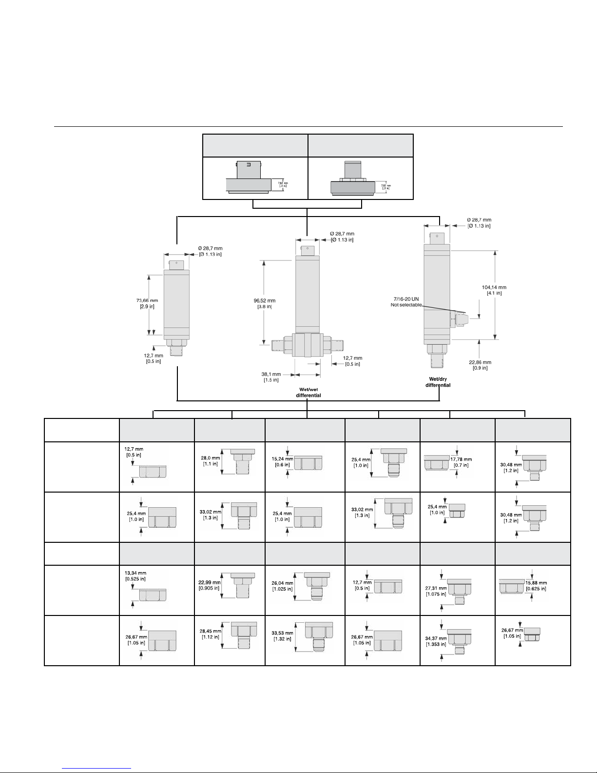
2.1 Physical Dimensions
Pressure ports
Less than
1000 psi
HPG
HPA
Code 5a
1/4-18 NPT female
Code 6a: 6-pin, vented,
Bendix style
Code 5b
1/4-18 NPT male
Code 5c
7/16-20 UNF female
Code 6bj: 5-pin vented,
M12 connector
HDW
Code 5d
7/16-20 UNF male
HDD
Code 5f
G 1/4 B female
Code 5g
G 1/4 B male
Greater than
1500 psi
Code 5h
1/8-27 NPT female
Less than
1000 psi
Greater than
1500 psi
Code 5i
1/8-27 NPT male
Code 5p
M12-1.5 male
Code 5q
M12-1.5 female
Code 5r
9/16-18 SAE male
Code 5s
9/16-18 SAE female
Sensing and Productivity Solutions 3
Page 6

Digital Pressure Sensor with CANopen®, Model DPS 50085804, Rev. B
2.2 Electrical Termination and Pin Assignment
Electrical connection can be selected from 6-pin Bendix connector or 5-pin M12 connector.
6-pin Bendix connector Pin Assignment
A CAN_SHLD
B CAN_V+
C CAN_GND
D CAN_H
E CAN_L
F NC
M12 electrical connector
5-pin M12 connector Pin Assignment
1 CAN_SHLD
2 CAN_V+
3 CAN_GND
4 CAN_H
5 CAN_L
2.3 Pressure Ports
See available pressure ports in physical dimension diagram
included in Section 2.1.
2.4 Pressure Media Compatibility
Media that is compatible with stainless steel 316L and
Hastelloy
®
.
2.5 Physical and Environmental Specications
Characteristic Parameter
Weight
(representative of
HPG & HPA)
Shock 100 g [11 ms] peak
Vibration
Compensated
temperature
range
Operating
and storage
temperature
range
Approvals
100 psi: 234 g [8.25 oz]
(1/4-18 NPT port with Bendix)
100 psi: 236 g [8.32 oz]
(1/4-18 NPT port with M12)
MIL-STD-810C, Figure 514.2-5, curve AK,
Table 514.2-V, random vibration test
[overall g rms = 20.7 min.]
4 °C to 60 °C [40 °F to 140 °F]
-25 °C to 85 °C [-13 °F to 185 °F]
CiA (CAN In Automation), CE Marked, Declaration of Conformity on request
2.6 Mechanical Specications
Characteristic Parameter
1
Media
Overload
(safe), positive
direction
Overload
(safe), negative direction
Overload
(burst), positive direction
Overload
(burst), negative direction
Pressure port 200% over capacity
Wetted parts
material
NOTES:
1. The wet/wet differential pressure sensor has two separate, welded
Hastelloy® diaphragms. In wet/dry unit, the wet port (high port) has
all-welded stainless steel and Hastelloy® construction. The dry port
(low port) has no isolation diaphragm.
gas, liquid
1000 psi and below: 4X full scale or 3000
psi, whichever is less
1500 psi and above: 4X full scale or 15000
psi, whichever is less
4X full scale or 250 psi, whichever is less
1000 psi and below: 3000 psi
1500 psi and above: 15000 psi
Ha C276 & 316L stainless steel
4 sensing.honeywell.com
2.7 Electrical Specications
Characteristic Parameter
Excitation 9 Vdc to 28 Vdc
Page 7
Digital Pressure Sensor with CANopen®, Model DPS 50085804, Rev. B
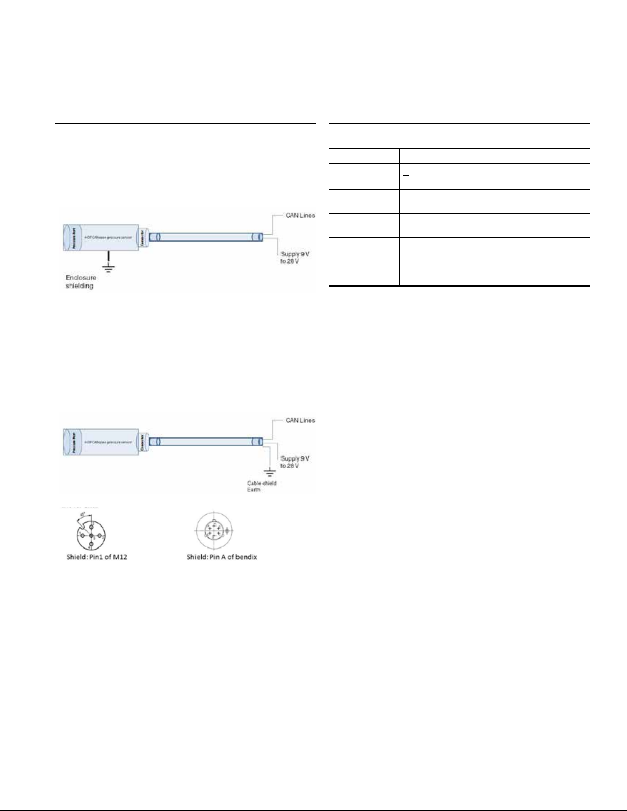
2.8 Recommended Grounding
If there is a provision to ground the enclosure at the application being used, use the recommended grounding method as
shown in Figure 1.
Figure 1. Recommended Shielding Diagram 1
If there is no provision to ground the enclosure in the application, this shielding method is preferred for wires that run longer.
The shielding of the cable can be connected to CAN_SHLD of
the connector (pin 1 of M12 or Pin A of Bendix) and it can be
grounded at the far end (see Figure 2).
Figure 2. Recommended Shielding Diagram 2
2.9 Performance Specications
At 25 °C [77 °F] and a rated excitation unless otherwise noted
Characteristic Parameter
<30 psi: ±0.25 %FS
Accuracy
ADC
resolution
Total Error
Band
User-congurable update
rate
Baud rate 125 kbps (default)
NOTES:
2. Includes pressure non-linearity (BFSL), pressure hysteresis and non-
repeatability. Thermal errors are not included.
3. Differential sensors are calibrated in positive direction and accuracy
specification is valid in positive direction only.
4. Includes zero error, span error, thermal effect on zero, thermal effect
on span, thermal hysteresis, pressure-non-linearity, pressure hysteresis and non-repeatability.
,
1. The wet/wet differential pressure sensor has two
2. Includes pressure non-linearity (BFSL), pressure
3. Differential sensors are calibrated in positive direction
4. Includes zero error, span error, thermal effect on zero,
2,3
>30 psi: ±0.1 %FS, ±0.25 %FS
12 bit
4
±2 %FS
250 Hz (max.); 10 Hz (default)
ATTENTION
separate, welded Hastelloy
unit, the wet port (high port) has all-welded stainless
steel and Hastelloy
has no isolation diaphragm.
hysteresis, and non-repeatability. Thermal errors are not
included.
and accuracy specification is valid in positive direction
only.
thermal effect on span, thermal hysteresis, pressurenon-linearity, pressure hysteresis, and non-repeatability.
®
®
diaphragms. In wet/dry
construction. The dry port (low port)
Sensing and Productivity Solutions 5
Page 8

Digital Pressure Sensor with CANopen®, Model DPS 50085804, Rev. B
CHAPTER 3 - INTRODUCTION
The Digital Pressure Sensor with CANopen®, Model DPS,
implements the standard CANopen
The CANopen
®
standards supported are shown in Table 1.
®
communications protocol.
These standards are available from CAN in Automation www.
can-cia.de.
3.1 Supported Standards
Table 1. Supported CANopen® Standards
CANopen®
CiA Standard
DS301 4.02
DR-303-2 1.1
DSP 305 2.2
DSP 404 1.0
Version Description
Application layer and communication profile
CANopen
®
units and prefixes
CANopen
®
and protocol
Measuring devices and closed
loop controllers
representation of SI
layer setting services
The Model DPS pressure sensor is provided with the CANo-
®
pen
default settings as shown in Table 2.
Table 2. CANopen® Default Settings
Parameter Default
Value
(Hex)
Node-ID 7F
COB-ID PDO
COB-ID SDO
COB-ID
EMERGENCY
180 +
Node-ID
600 +
Node-ID
80 +
Node-ID
COB-ID NMT 00
COB-ID SYNC 80
LSS Master 7E5
LSS Slave 7E4
BOOTUP
HEARTBEAT
COB-ID
Bit rate
700 +
Node-ID
125
Kbps
Description
The Node-Identifier used for
CANopen
®
communications
The communications object identifier of the process data object
The communications object identifier of the service data object
The communications object identifier of the emergency object
The communications object identifier of the network management
object
The communications object
identifier of the synchronization
object
The identifier of the layer settings
service master (host)
The identifier of the layer settings
service slave (Digital Pressure
Sensor with CANopen
®
Series)
The communications object identifier for the heartbeat object
The bit rate that is used for CAN
communications. [Bit rate is
mentioned in decimal]
6 sensing.honeywell.com
Page 9

Digital Pressure Sensor with CANopen®, Model DPS 50085804, Rev. B
CHAPTER 4 - SETTING UP
4.1 Procedure to Get Started
In order to operate in the host network it is necessary to ensure:
1. The Node-ID of the Digital Pressure Sensor with
CANopen
on the CANbus network.
2. The bit rate of the Digital Pressure Sensor with CANopen
Model DPS, matches that of the network to which it is
being connected.
These parameters are configured using the layer settings services. These parameters are configured prior to connecting the
Model DPS in the host network.
Table 3. Point to Point Node-ID Conguration
®
, Model DPS, is not the same as any other node
4.2 Node-ID Conguration
The Node-ID is used to provide unique communication object
identifiers for each CANopen
ing of the Node-ID can be performed:
1. Prior to connection using the switch mode global
command called Point-to-Point Configuration.
®
,
2. On the target network using the switch mode selective
command called Network Configuration.
Table 3 shows the process of performing point-to-point NodeID Configuration. Table 4 shows the process of performing
Node-ID Configuration on network.
®
device on the network. Configur-
ID(hex) DLC Data(Hex) Comment Direction w.r.t Digital Pressure
Sensor with CANopen
®
000 2 80 7F Preoperational node ID 7F Receive
7E5 8 04 01 00 00 00 00 00 00 Configuration state Receive
7E5 8 11 7E 00 00 00 00 00 00 Set node ID 7E Receive
7E4 8 11 00 00 00 00 00 00 00 Response ok Transmit
7E5 8 17 00 00 00 00 00 00 00 Store configuration Receive
7E4 8 17 00 00 00 00 00 00 00 Response ok Transmit
7E5 8 04 00 00 00 00 00 00 00 Waiting state Receive
000 2 81 7F Reset node ID -7F Receive
77E 1 00 Boot up message Transmit
Table 4. Node-ID Conguration On Network
ID(hex) DLC Data(Hex) Comment Direction w.r.t Digital Pressure
Sensor with CANopen
000 2 80 7E Preoperational node ID 7E Receive
7E5 8 40 62 03 00 00 00 00 00 Vendor ID Receive
7E5 8 41 50 31 44 00 00 00 00 Product code Receive
7E5 8 42 00 00 01 00 00 00 00 Revision no. Receive
Serial number, where xx xx xx xx
7E5 8 43 xx xx xx xx 00 00 00
is the serial number of the device
Receive
given along with the Model DPS unit
7E4 8 44 00 00 00 00 00 00 00 Response ok Transmit
7E5 8 11 7F 00 00 00 00 00 00 Set node ID 7F Receive
7E4 8 11 00 00 00 00 00 00 00 Response ok Transmit
7E5 8 17 00 00 00 00 00 00 00 Store configuration Receive
7E4 8 17 00 00 00 00 00 00 00 Response ok Transmit
7E5 8 04 00 00 00 00 00 00 00 Waiting state Receive
000 2 81 7E Reset node ID -7E Receive
77F 1 00 Boot up message Transmit
®
Sensing and Productivity Solutions 7
Page 10

Digital Pressure Sensor with CANopen®, Model DPS 50085804, Rev. B
4.3 Bit Rate Conguration
Configuring of the Bit Rate can be performed:
1. Prior to connection using the switch mode global
command called Point-to-Point configuration.
2. On the target network using the switch mode selective
command called Network Configuration.
Table 5 shows the process of performing point-to-point Bit Rate
configuration. Table 6 shows the process of performing Bit
Rate configuration on network.
Table 5. Point-to-Point Bit Rate Conguration
ID(hex) DLC Data(Hex) Comment Direction w.r.t Digital Pressure
Sensor with CANopen
000 2 80 7f Preoperational node ID 7f Receive
7E5 8 04 01 00 00 00 00 00 00 Configuration state Receive
7E5 8 13 00 04 00 00 00 00 00 Set bit rate 125 kbit 04 Receive
7E4 8 13 00 00 00 00 00 00 00 Response ok Transmit
7E5 8 17 00 00 00 00 00 00 00 Store configuration Receive
7E4 8 17 00 00 00 00 00 00 00 Response ok Transmit
7E5 8 04 00 00 00 00 00 00 00 Waiting state Receive
000 2 01 00 Enter operational state Receive
1ff 4 Pressure data Transmit
®
Table 6. Bit Rate Conguration on Network
ID(hex) DLC Data(Hex) Comment Direction w.r.t Digital Pressure
Sensor with CANopen
000 2 80 7E Preoperational node Id 7E Receive
7E5 8 40 62 03 00 00 00 00 00 Vendor ID Receive
7E5 8 41 50 31 44 00 00 00 00 Product code Receive
7E5 8 42 00 00 01 00 00 00 00 Revision no. Receive
Serial number, where xx xx xx xx
7E5 8 43 xx xx xx xx 00 00 00
7E4 8 44 00 00 00 00 00 00 00 Response ok Transmit
7E5 8 13 00 04 00 00 00 00 00 Set bit rate 125 Kbit 04 Receive
7E4 8 13 00 00 00 00 00 00 00 Response ok Transmit
7E5 8 17 00 00 00 00 00 00 00 Store configuration Receive
7E4 8 17 00 00 00 00 00 00 00 Response ok Transmit
7E5 8 04 00 00 00 00 00 00 00 Waiting state Receive
000 2 01 00 Enter operational state Receive
1ff 4 Pressure data Transmit
is the serial number of the device
given along with the Model DPS unit
Receive
®
8 sensing.honeywell.com
Page 11

Digital Pressure Sensor with CANopen®, Model DPS 50085804, Rev. B
The new bit rate is valid after a reset of the device. It is highly
recommended to power off the CANopen
and change the bit rate of the master to the desired value (125
kbit/s in this example). Performing a NMT reset node command
will lead to error frames on the CANbus, because the master
still has the previous bit rate. The available bit rates are given
in Table 7.
®
slave device first
Table 7. Available Bit Rates
Bit Rate Table Index
1000 Kbit 0
500 Kbit 2
250 Kbit 3
125 Kbit 4
100 Kbit 5
50 Kbit 6
4.4 Activate Bit Timing Command
Send the activate bit timing command, as shown in Table 8,
to re-start with the selected bit rate, before storing the bit rate.
The switch delay is an Intel format unsigned integer number
that represents a time delay in mS, e.g. 3E816 = 1000 mS.
This time delay is used for two periods on the Digital Pressure
Sensor with CANopen
will not be applied until the delay is expired; secondly, no messages shall be sent by the Model DPS pressure sensor until the
delay has expired once more.
Start the heartbeat and let it run at 100 ms. Then, set the bit
rate. The heartbeat still runs. Then activate the bit timing and
set the activation time to 1 sec. Then after 2 sec, the heartbeats start up again at the new bit rate.
®
, Model DPS. First, the new bit timing
Table 8. Activate Bit Timing
ID(hex) DLC Data(Hex) Comment Direction w.r.t Digital Pres-
sure Sensor with
CANopen
67f 8 22 17 10 00 64 00 00 00
5ff 8 60 17 10 00 00 00 00 00 Response ok Transmit
7ff 1 7f Heartbeat message every 100 millisec Transmit
000 2 80 7f Enter pre-operational state Receive
7E5 8 04 01 00 00 00 00 00 00 Configuration state Receive
7E5 8 13 00 04 00 00 00 00 00 Set bit rate 125 Kbit 04 Receive
7E4 8 13 00 00 00 00 00 00 00 Response ok Transmit
7E5 8 04 00 00 00 00 00 00 00 Waiting state Receive
7ff 1 7f Heartbeat message every 100 millisec Transmit
7ff 1 7f Heartbeat message every 100 millisec Transmit
7E5 8 04 01 00 00 00 00 00 00 Configuration state Receive
7E5 8 15 E8 03 00 00 00 00 00 Configuration state Receive
7E5 8 04 00 00 00 00 00 00 00 Waiting state Receive
7ff 1 7f Heartbeat message after 2 secs Transmit
7ff 1 7f Heartbeat message every 100 millisec Transmit
Enable heartbeat message – once
every 100 millisec
Receive
®
Sensing and Productivity Solutions 9
Page 12

Digital Pressure Sensor with CANopen®, Model DPS 50085804, Rev. B
Power-on
CHAPTER 5 - NETWORK MANAGEMENT
The Digital Pressure Sensor with CANopen®, Model DPS, is
a CANopen
diagram and the communication objects supported by each
state.The Model DPS pressure sensor supports minimum bootup. Minimum boot-up devices enter the pre-operational state
automatically after finishing the device initialization.
®
NMT slave. Figure 3 shows the state transition
5.1 Network Transition Diagram
In order to operate in the host network it is necessary to ensure:
1. The Node-ID of the Digital Pressure Sensor with
CANopen
on the CANbus network.
2. The bit rate of the Digital Pressure Sensor with CANopen
Model DPS, matches that of the network to which it is
being connected.
These parameters are configured using the layer settings
services. These parameters are configured prior to connecting
the Digital Pressure Sensor with CANopen
host network.
®
, Model DPS, is not the same as any other node
®
, Model DPS, in the
®
The letters (in brackets) show which communication object
types are allowed inside the different states:
a. NMT, b. LSS, c. SDO, d. Emergency, e. PDO,
f. Boot-up, g. Synchronization
The state transitions and the NMT command specifiers (in
brackets):
1: Start remote node (0x01)
2: Stop remote node (0x02)
3: Enter pre-operational state (0x80)
4: Reset node (0x81)
5: Reset communication (0x82)
6: Device initialization finished, enter pre-operational state
,
automatically, send boot-up message
The NMT message has the following format:
COB-ID Byte0 Byte1
0x0000 CS Node-Id
Figure 3. NMT State Transition Diagram
Initialising
(f)
5
Pre-operational
(a, b, c, d)
1
Operational
(a, b, c, d, e)
3
3
2
Stopped
1
2
46
(a, b)
10 sensing.honeywell.com
Page 13

Digital Pressure Sensor with CANopen®, Model DPS 50085804, Rev. B
CS is the Command Specifier, which can have the following values:
NMT
Service
Start
remote
node
Stop
remote
node
Enter preoperational state
Reset
node
Reset
communication
Command
Specier
(hex)
1
2
80
81
82
Description Table 9: Start Remote Node
®
The Digital Pressure Sensor with CANopen
into operational state when Start remote node command is sent
from the NMT master. In this state, the Digital Pressure Sensor
with CANopen
®
starts giving out pressure data every 100 mil-
lisecond.
, Model DPS, enters
ID(hex)
Byte 0
Cmd
Byte 1
Node-ID
00 1 7F
Table 10: Stop Remote Node
The stop remote node command causes the Digital Pressure
Sensor with CANopen
®
, Model DPS, to enter the stopped state.
In the stopped state the NMT and LSS are available.
ID(hex)
Byte 0
Cmd
Byte 1
Node-ID
00 2 7F
Table 11: Enter Pre-operational
State
The Digital Pressure Sensor with CANopen
®
, Model DPS, enters
preoperational state after initialization. When the pre-operational
state is entered, after initialization, a boot-up message is sent as
shown in Table 12.
ID(hex)
Byte 0
Cmd
00 80 7F
Table 12: Boot-up Message
ID(hex)
Byte 0
Cmd
700 +
Node-ID
Byte 1
Node-ID
–
–
77F 00 –
The reset node command causes the Digital Pressure Sensor
with CANopen
®
, Model DPS, to re-load the whole object dictionary from non-volatile memory. Table 13 shows the reset node
command.
The reset communications command causes the Digital Pressure Sensor with CANopen
®
, Model DPS, to re-load the communications area of the object dictionary from non-volatile memory.
Table 14 shows the reset communication command.
Table 13: Reset Node
ID(hex)
Byte 0
Cmd
Byte 1
Node-ID
00 81 7F
Table 14: Reset Command
ID(hex)
Byte 0
Cmd
Byte 1
Node-ID
00 82 7F
Sensing and Productivity Solutions 11
Page 14

Digital Pressure Sensor with CANopen®, Model DPS 50085804, Rev. B
CHAPTER 6 - HEARTBEAT PROTOCOL
The NMT master will use the heartbeat message produced by
the Digital Pressure Sensor with CANopen
determine that the node is present on the network. The Model
DPS will send a heartbeat message every n mS, where n is
the heartbeat producer time available at object 0x1017. If the
heartbeat producer time is zero then no heartbeat message will
be transmitted. Table 15 depicts the Heartbeat message. The
default heartbeat producer time for the Digital Pressure Sensor
with CANopen
®
, Model DPS, is zero.
®
, Model DPS, to
6.1 Heartbeat Message
Table 15. Digital Pressure Sensor with CANopen®
Heartbeat Message
COB-ID(hex) Byte 0
0x700+Node-ID State
Where state can have any of the following values
Table 16. Heartbeat Protocol States
COB-ID(hex) Byte 0
0 Boot-up
4 Stopped
5 Operational
7F Pre-operational
CHAPTER 7 - PROCESS DATA OBJECTS
The real-time process data transfer is performed by means of
process data objects (PDO). Upon entering the operational
state, the Digital Pressure Sensor with CANopen
starts transmitting the pressure in 32 bit signed integer format
at an update rate of 100 millisecs.
®
, Model DPS,
7.1 PDO Transmission Type
The transmission type parameter of a PDO specifies the
transmission mode (synchronous, event driven) as well as the
triggering mode.
Transmission modes:
• Synchronous
• Event-driven
Synchronous
For synchronous PDOs, the transmission type also specifies the transmission rate in the form of a factor based on the
basic SYNC object transmission period. A transmission type
of 0 means that the message shall be transmitted after occurrence of the SYNC (acyclic – not periodically), only if an event
occurred before the SYNC. The transmission type 1 means
that the message shall be transmitted with every SYNC object
(cyclic). A transmission type of n means that the message shall
be transmitted with every n-th SYNC object.
Event-driven
12 sensing.honeywell.com
Event-driven TPDOs are transmitted without any relation to the
SYNC object.
Triggering modes
In the Digital Pressure Sensors with CANopen®, Model DPS,
two message-triggering modes are distinguished:
• Event-driven
• Synchronously triggered
Event- and timer-driven
Message transmission is either triggered by the occurrence of
an application-specific event specified in manufacturer-specific
profile or if a specified time (event-time) has elapsed without
occurrence of an event.
Synchronously triggered
Message transmission is triggered by the occurrence of the
SYNC object. The trigger condition is the number of sync and
optionally an internal event. The Model DPS supports the transmission types listed in the Table 17.
Page 15

Digital Pressure Sensor with CANopen®, Model DPS 50085804, Rev. B
‘Table 17. Transmission Types Supported by the Digital Pressure Sensor with CANopen®, Model DPS
Transmission
(hex)
0
1-F0
FE
FF
Description
Acyclic, synchronous transmission. The Digital Pressure Sensor with CANopen
®
, Model
DPS, will transmit a PDO message after
occurrence of the SYNC, but only if an event
(change in the pressure data) occurred
before the SYNC.
Cyclic, synchronous transmission. The
Digital Pressure Sensor with CANopen
®
,
Model DPS, will transmit the PDO message
on reception of the nth SYNC message,
where n is 1 to 240.
Asynchronous transmission. The Digital
Pressure Sensor with CANopen
®
, Model
DPS, will transmit the PDO message at the
time interval defined by the event time (by
default it transmits pressure data every 100
millisec). The PDO is transmitted without any
relation to the SYNC object.
Asynchronous transmission. The Digital
Pressure Sensor with CANopen
®
, Model
DPS, will transmit the PDO message at the
time interval defined by the event time (by
default it transmits pressure data every 100
millisec).The PDO is transmitted without any
relation to the SYNC object.
7.2 Changing the Output Units
The default unit of the process value is psi. The physical units
of the process value can be read or modified by using the object 6131. When the units are changed using the object 6131,
the units of all the objects associated with process value is
changed internally by the Digital Pressure Sensor with CANo-
®
pen
, Model DPS. Table 18 contains the list of the objects that
are associated with process value. The Model DPS supports
only 1 PDO.
Table 18. List of Objects Affected by Unit Change
Object Description
6148 AI span start
6149 AI span end
6124 AI input offset
6130 AI input process value REAL32
2006 Span
Table 19. Command to Change Physical Units from psi to Bar
ID(hex) DLC Data(Hex) Description Direction w.r.t Digi-
Byte0 Byte1 Byte2 Byte3 Byte4 Byte5 Byte6 Byte7
67F 8 40 31 61 01 00 00 00 00
Read the current
unit
5FF 8 60 31 61 01 00 00 AB 00 Current unit is psi Transmit
67F 8 40 30 61 01 00 00 00 00 Read process value Receive
5FF 8 60 30 61 01 50 C3 00 00 50 psi Transmit
67F 8 22 31 61 01 00 00 4E 00
Change the unit to
bar
5FF 8 60 31 61 01 00 00 00 00 Return ok Transmit
67F 8 40 31 61 01 00 00 00 00
Read the current
unit
5FF 8 60 31 61 01 00 00 4E 00 Current unit is bar Transmit
67F 8 40 30 61 01 00 00 00 00 Read process value Receive
5FF 8 60 30 61 01 78 0D 00 00 3.448 bar Transmit
tal Pressure Sensor
with CANopen
®
Receive
Receive
Receive
Sensing and Productivity Solutions 13
Page 16

Digital Pressure Sensor with CANopen®, Model DPS 50085804, Rev. B
The units can be stored in EEPROM by using the store command, i.e. object 0x1010. Also the default unit of PSI can be
restored using the restore command i.e. object 0x1011. Table
20 provides a list of units that the Digital Pressure Sensor with
CANopen
®
, Model DPS, supports.
Table 20. Units Supported by the Digital Pressure
Sensor with CANopen®, Model DPS
Unit Type Unit Code
Non-SI psi 00 00 AB 00
SI Bar 00 00 4E 00
SI KPa 00 00 22 03
7.3 PDO Mapping
The Digital Pressure Sensor with CANopen®, Model DPS, allows two different objects to be mapped into the process data
object:
1. Pressure in signed integer format (default)
2. Raw pressure data
The mappable objects are shown in Table 21.
Table 21. Objects That Can Be Mapped to the PDO
Object (hex) Sub Index
(hex)
6130 1 Pressure reading REAL32
7100 1 Pressure reading INT16
The default mapping of the Digital Pressure Sensor with CANo-
®
pen
, Model DPS, is shown in Table 22.
Table 22. Digital Pressure Sensor with CANopen®
Initial PDO Map
Object
Number
(hex)
1A00 00 01 1 object mapped
1A00 01 20013061
Sub
Index
(hex)
Value (hex) Description
Description
1st object is process value
stored at 6130, sub index
1, length 32 bits. This can
be changed to filed value
7100, subindex 1, length
16 bits
CHAPTER 8 - SERVICE DATA OBJECTS
The Service Data Object (SDO) is used to access the object
dictionary (OD) of a device. The requester of the OD access
is called the client and the CANopen
®
device, whose OD is
accessed and services the request, is called the server. The
client CAN-message as well as the reply server CAN-message
always contains 8 bytes (although not all bytes necessarily
contain meaningful data). A client request is always confirmed
by a reply from the server. The Digital Pressure Sensor with
CANopen
®
, Model DPS, supports only one server SDO and no
client SDOs.
8.1 SDO Transfer
There are two mechanisms for SDO transfer:
• Expedited transfer: used for data objects up to 4 bytes in
length.
• Segmented transfer: for objects with length > 4 bytes.
The Digital Pressure Sensor with CANopen
lows only expedited SDO access (single CAN frame read/write
and response) to (and from) the object dictionary.
The Model DPS is capable of detecting errors within the SDO
protocol. If an error is detected then the Digital Pressure Sensor with CANopen
®
, Model DPS, replies with an SDO abort
message. Table 23 contains the supported abort codes and
their description.
Table 23. SDO
Abort Code
(hex)
0504
001160504
0001
0601 0001
0601 0002 Attempt to write a read only object
0602 0000 Object does not exist in object dictionary
0604 0041 Object cannot be mapped to the PDO
0609 0011
0609 0031
0800 0000 General error
Description
Client/server command specifier not valid or
unknown
Attempt to read a write only object. Attempt
to read a write only object. Attempt to read a
write only object. Attempt to read a write only
object. Attempt to read a write only object to
read. Attempt to read a write only object. Attempt to read a write only object
Sub-index does not exist. Attempt to read a
write-only object. Attempt to read a write-only
object
Value of parameter exceeded (only for write
access)Value of parameter exceeded (only for
write access) Value of parameter exceeded
(only for write access)
®
, Model DPS, al-
14 sensing.honeywell.com
Page 17

Digital Pressure Sensor with CANopen®, Model DPS 50085804, Rev. B
CHAPTER 9 - EMERGENCY OBJECTS
The Digital Pressure Sensor with CANopen®, Model DPS, will
transmit an emergency object if an internal error is detected or
a source of error is removed. The Model DPS supports the error
codes listed in Table 24.
9.1 Supported Emergency Codes
Table 24. Digital Pressure Sensor with CANopen®
Supported Emergency Codes
Emergency
Error Code
2201 03 Sensor failure
3201 05 Over flow / under flow
5000 81 EEPROM error
8120 11 CAN in error passive mode
8140 11 Recovered from bus off
Error Register Description
CHAPTER 10 - OPERATION
This section describes the fundamental operation and configurations available for the Digital Pressure Sensor with CANo-
®
pen
, Model DPS. The object dictionary supported is provided
in Appendix 1.
10.1 Getting Pressure Data
The Digital Pressure Sensor with CANopen®, Model DPS, by
default sends out 32 bit pressure data (in decimalized integer format, in psi units), every 100 millisec. Table 25 shows
the sequence of messages necessary to obtain the pressure
reading from the Model DPS. Provide the excitation voltage
to the Digital Pressure Sensor with CANopen
transmits boot-up message to PC on identifier 77F. Host application transmits START REMOTE NODE command. When
START REMOTE NODE command is transmitted, by the host,
the Model DPS
pressure data (in decimalized integer format, in psi units) every
100 millisec.
starts transmitting the PDO containing the 32-bit
®
, Model DPS,
10.2 Interpreting the Pressure Data
Table 25. Getting the Pressure Data
ID
(hex)
77F 1 00
000 2 01 7F
1FF 4 05 00 00 00
DLC Data (hex) Description Direction w.r.t Digi-
Byte0 Byte1 Byte2 Byte3 Byte4 Byte5 Byte6 Byte7
The Digital Pressure Sensor with CANopen®, Model DPS,
provides the pressure reading in 32 bit signed integer values
of Intel format, i.e. LSB first. The actual value of the pressure
reading depends on the number of decimal digits that should
be used with these integer values. The decimal digits used can
be read from the Model DPS using an SDO access to object
6132. In Digital Pressure Sensor with CANopen
the number of decimal digits is 3. So the pressure data can be
interpreted as 00000.005 psi.
Boot-up message.
Node ID 7F
Send command with
node Id 7F
Digital Pressure Sensor with CANopen
Model DPS, starts
transmitting PDO
containing the pressure data every 100
millisecs
®
,
®
, Model DPS,
tal Pressure Sensor
with CANopen
Transmit
Receive
Transmit
®
Sensing and Productivity Solutions 15
Page 18

Digital Pressure Sensor with CANopen®, Model DPS 50085804, Rev. B
10.3 Mapping Raw Pressure Data in PDO
Table 26 shows the procedure to map the Raw Pressure data
into PDO.
10.4 Transmission type conguration
The Digital Pressure Sensor with CANopen®, Model DPS, can
be configured to give out the pressure reading in three different
ways:
1. The PDO is transmitted when a SYNC pulse is received,
providing the data is marked as updated. The data is
marked as updated whenever the pressure data changes.
An example of this transmission type is shown in Table 20.
Table 26. Map Raw Pressure Data into PDO
ID
(hex)
67F 8 22 00 18 01 FF 01 00 C0 Disable PDO Receive
5FF 8 60 00 18 01 00 00 00 00 Return OK Transmit
67F 8 22 00 1A 00 00 00 00 00
5FF 8 60 00 1A 00 00 00 00 00 Return ok Transmit
67F 8 22 00 1A 01 10 01 00 71 Change mapping Receive
5FF 8 60 00 1A 01 00 00 00 00 Return ok Transmit
67F 8 2F 00 1A 00 01 00 00 00
5FF 8 60 00 1A 00 00 00 00 00 Return ok Transmit
67F 8 22 00 18 01 FF 01 00 40 Turn PDO on Receive
5FF 8 60 00 18 01 00 00 00 00 Return OK Transmit
DLC Data (hex) Description Direction w.r.t Digi-
Byte0 Byte1 Byte2 Byte3 Byte4 Byte5 Byte6 Byte7
2. The PDO is transmitted with every nth SYNC pulse
received, where n is a value
3. Between 1 and 240. An example of this transmission type
is shown in Table 21.
4. The PDO is transmitted when the Digital Pressure Sensor
with CANopen
happens every 100 millisec by default. This event timer
value can be configured using the object 1800 with
subindex 05. This transmission type is independent of
the SYNC pulse. An example of this transmission type is
shown in Table 22.
®
, Model DPS, event timer expires which
tal Pressure Sensor
with CANopen
Write TPDO MAP
disable
Write TPDO MAP
enable
Receive
Receive
®
16 sensing.honeywell.com
Page 19

Digital Pressure Sensor with CANopen®, Model DPS 50085804, Rev. B
Table 27. Synchronous Acyclic PDO Transmission
ID
(hex)
67F 8 22 00 18 02 00 00 00 00
5FF 8 60 00 18 02 00 00 00 Return ok Transmit
80 0 SYNC command Receive
1FF 4 00 10 00 00
80 0 SYNC command Receive
1FF 4 00 20 00 00
DLC Data (hex) Description Direction w.r.t
Digital Pressure
Byte0 Byte1 Byte2 Byte3 Byte4 Byte5 Byte6 Byte7
Sensor with
CANopen
®
Change the transmission type to synchronous
Receive
(acyclic)
Digital Pressure Sensor with CANopen
Model DPS, transmits the
pressure data if it has
®
,
Transmit
changed from the previous value. [1 psi]
Digital Pressure Sensor with CANopen
Model DPS, transmits the
pressure data if it has
®
,
Transmit
changed from the previous value. [2 psi]
Table 28. Synchronous Cyclic PDO Transmission (Cyclic with Every Sync)
ID
(hex)
67F 8 22 00 18 02 03 00 00 00
5FF 8 60 00 18 02 00 00 00 Return ok Transmit
80 0 SYNC command Receive
80 0 SYNC command Receive
80 0 SYNC command Receive
1FF 4 00 20 00 00
DLC Data (hex) Description Direction w.r.t Digi-
Byte0 Byte1 Byte2 Byte3 Byte4 Byte5 Byte6 Byte7
tal Pressure Sensor
with CANopen
Change the transmission type to synchronous (cyclic).
The Digital Pressure
Sensor with CANo-
®
pen
, Model DPS,
Receive
should transmit data
on 3rd SYNC
Digital Pressure Sensor with CANopen
®
,
Model DPS, transmits the pressure
Transmit
data reception of 3rd
SYNC commands.
[2 psi]
®
Sensing and Productivity Solutions 17
Page 20

Digital Pressure Sensor with CANopen®, Model DPS 50085804, Rev. B
Table 29. Asynchronous PDO Transmission
ID
(hex)
67F 8 22 00 18 02
5FF 8 60 00 18 02 00 00 00 Return ok Transmit
67F 8 22 00 18 05 E8 03 00 00
5FF 8 60 00 18 05 00 00 00 00
DLC Data (hex) Description Direction w.r.t Digi-
Byte0 Byte1 Byte2 Byte3 Byte4 Byte5 Byte6 Byte7
tal Pressure Sensor
with CANopen
®
Change the transmission type to
FE (or
FF)
00 00 00
acyclic. The Digital
Pressure Sensor with
CANopen
®
, Model
Receive
DPS, transmits PDO
every 100 millisec
Write to PDO communications object
event. Timer with
Receive
value of 1000 mS.
The Digital Pressure
Sensor with CANo-
®
pen
, Model DPS,
starts transmitting
Transmit
the PDO every 1000
millisec
18 sensing.honeywell.com
Page 21

Digital Pressure Sensor with CANopen®, Model DPS 50085804, Rev. B
10.5 Calibration
The Digital Pressure Sensor with CANopen®, Model DPS, allows auto zero correction by using the object 0x6125. When
autozero correction is applied, all the objects associated with
process value are changed internally by the Model DPS. The
objects related to process value are given in Table 18. An example of how to achieve zero correction is shown in the Table
30.
The auto zero value can be stored in EEPROM by using the
store command, i.e. object 0x1010. Also the default offset can
be restored using the restore command, i.e. object 0x1011.
Table 30. Auto Zero Command
ID
(hex)
67F 8 22 25 61 01 7A 65 72 6F
5FF 8 60 25 61 01 00 00 00 00 Return ok Transmit
DLC Data (hex) Description Direction w.r.t Digi-
Byte0 Byte1 Byte2 Byte3 Byte4 Byte5 Byte6 Byte7
Apply Zero Pressure
Performs an auto
zero on the current
pressure reading.
Whatever was the
offset when zero
pressure is applied
will now be nullified
tal Pressure Sensor
with CANopen
Receive
®
Sensing and Productivity Solutions 19
Page 22

Digital Pressure Sensor with CANopen®, Model DPS 50085804, Rev. B
APPENDIX - OBJECT DICTIONARY
Communication Prole Objects 0x1000 – 0x1FFF
Index SubIndex Name Description
0x1000 0x00 Device type The object describes the type of the logical device and its functionality
®
0x1001 0x00 Error register
0x1003 0x00
0x1005 0x00
0x1008 0x00
0x1009 0x00
0x100A 0x00
Pre-defined error
field
COB-ID sync message
Manufacturer
device name
Manufacturer
hardware version
Manufacturer software version
This object provided error information. The CANopen
into this object. It is a part of an emergency object
This object provides the errors that occurred on the CANopen
signaled via the emergency object. In doing so it provides an error history
This object indicates the configured COB-ID of the synchronization object (SYNC).
Further, it defines whether the CANopen
®
device generates the SYNC
This object provides the name of the device as given by the manufacturer
This object provides the manufacturer hardware version description
This object provides the manufacturer software version description
This object controls the saving of parameters in non-volatile memory. This command
0x1010 0x00-0x01 Store parameters
stores: 1) input offset, 2) span end, 3) span start, 4) heartbeat time, 5) physical
units, 6) auto zero, and 7) span
With this object, the default values of parameters according to the communication
0x1011 0x00-0x01
Restore default
parameters
profile, device profile, and application profile are restored. This command restores
1) input offset, 2) span end, 3) span start, 4) heartbeat time, 5) physical units, 6)
autozero, and 7) span
0x1014 COB-ID EMCY This object indicates the configured COB-ID for the EMCY write service
0x1017
Producer heartbeat time
The producer heartbeat time indicates the configured cycle time of the heartbeat
0x1018 0x00-0x04 Identity object This object provides general identification information of the CANopen
0x1200 0x00-x02
0x1800
0x00-0x02
and 0x05
0x1A00 0x00-0x08
SDO server parameter
TPDO communication parameter
TPDO mapping
parameter
This object contains the communication parameters for the PDOs the CANopen
device is able to transmit
This object contains the mapping for the PDOs the device is able to transmit
device maps internal errors
®
device and were
®
device
®
20 sensing.honeywell.com
Page 23

Digital Pressure Sensor with CANopen®, Model DPS 50085804, Rev. B
APPENDIX - OBJECT DICTIONARY, continued
CiA Device Prole Objects 0x6000 – 0x9FFFF
Index SubIndex Name Description
0x6110 0x00-x01 AI sensor type Specifies the type of sensor, which is connected to the analogue input
0x6124 0x00-0x01 AI input offset
0x6125 0x00-0x01 Auto sero
0x6131 0x00-x01 AI physical units
0x6132 0x00-x01 AI decimal digits
0x6148 0x00-0x01 AI span start
0x6149 0x00-0x01 AI span end
0x6130 0x00-x01
0x7100 0x00-x01
AI process value
(integer)
AI field value
(integer)
This object defines the additional offset value for the analogue input channel. It is
scaled in physical unit of process value
Writing a signature value of "zero“ to this object way that the actual AI input PV becomes zero. Along with the input offset value, this cycle is performed one time
This object assigns SI units and prefixes for the process values within the analogue
input function block
This object describes the number of decimal digits following the decimal point for
interpretation of data types Integer8, Integer16, and Integer32
This value specifies the lower limit where process values are expected. Process
values that are lower than this limit are marked as negative overloaded
This value specifies the upper limit where process values are expected. Process
values exceeding this limit are marked as positive overloaded
This object represents the result of the input scaling block and gives the measured
quantity scaled in the physical unit of process values
This object represents the raw ADC counts
Manufacturer Specic Objects 0x2000- 0x27FF
Index SubIndex Name Description
0x2002 0x00 Acquisition time
0x2003 0x00
0x2004 0x00
0x2005 0x00
0x2006 0x00 Pressure span Pressure span value RD
0x2007 0x00
0x2008 0x00
0x2009 0x00
0x200A 0x00 Pressure coeff1 Coefficient 1 used for calibration RD
0x200B 0 Pressure coeff2 Coefficient 2 used for calibration RD
0x200C 0 Pressure offset Offset used for calibration RD
0x200D 0 Sensor type Type of sensor: 1 for absolute, 2 for gauge, 3 for differential RD
0x200E 0 Serial number Serial number of the device RD
Acquisition interval
Pressure span
overflow count
Pressure span
underflow count
Last calibration
year
Last calibration
month
Last calibration
day
The time taken by the ADC to acquire data. The value to be expected is
15 microsecs
Time at which the data is captured form the ADC. The value to be expected is 1 millisec
Counts the number of times the pressure value crosses the maximum
span
Counts the number of times the pressure value crosses the minimum span RD
The year of the date on which it was calibrated last time RD
The month of the date on which it was calibrated last time RD
The day of the date on which it was calibrated last time RD
RD
RD
RD
Sensing and Productivity Solutions 21
Page 24

WARRANTY/REMEDY
Honeywell warrants goods of its manufacture as being free of
defective materials and faulty workmanship. Honeywell’s stan-
dard product warranty applies unless agreed to otherwise by
Honeywell in writing; please refer to your order acknowledge-
ment or consult your local sales office for specific warranty
details. If warranted goods are returned to Honeywell dur-
ing the period of coverage, Honeywell will repair or replace,
at its option, without charge those items it finds defective.
The foregoing is buyer’s sole remedy and is in lieu of all
other warranties, expressed or implied, including those of
merchantability and tness for a particular purpose. In no
event shall Honeywell be liable for consequential, special,
or indirect damages.
While we provide application assistance personally, through
our literature and the Honeywell web site, it is up to the custom-
er to determine the suitability of the product in the application.
Specifications may change without notice. The information we
supply is believed to be accurate and reliable as of this print-
ing. However, we assume no responsibility for its use.
Find out more
Honeywell serves its customers through
a worldwide network of sales offices,
representatives and distributors. For
application assistance, current specifications, pricing or name of the nearest
Authorized Distributor, contact your local
sales office.
To learn more about Honeywell’s test
and measurement products,
call +1-614-850-5000, visit
measurementsensors.honeywell.com,
or e-mail inquiries to
info.tm@honeywell.com
Honeywell Sensing and Productivity Solutions
9680 Old Bailes Road
Fort Mill, SC 29707
honeywell.com
50085804, Rev. B IL50 GLO
April 2016
Copyright © 2016 Honeywell International Inc. All rights reserved.
Hastelloy
CiA
®
is the registered trademark name of Haynes International, Inc.
®
and CANopen® are registered trademarks of CAN in Automation e.V.
 Loading...