

Page 1
Product of US Issue 5 - 05/2008 EN1I-6208
DPR180/DPR250
PCMCIA OPTION
MANUAL
Page 2

Product of US Issue 5 - 05/2008 EN1I-6208
Page 3

PCMCIA Option Manual
i
TABLE OF CONTENTS
1. OVERVIEW ...................................................................................................................................................1
1.1
WARNING ......................................................................................................................................................1
1.2
MAIN FUNCTIONS ...........................................................................................................................................2
2. INSTALLATION
............................................................................................................................................3
2.1
INSTALLING THE PCMCIA OPTION BOARD .......................................................................................................3
3. OPERATION
...............................................................................................................................................13
3.1
OVERVIEW...................................................................................................................................................13
3.1.1 PCMCIA card standard compatibility
..................................................................................................13
3.1.2 PCMCIA card handling
.......................................................................................................................13
3.1.3 Archives summary
..............................................................................................................................14
3.1.4 DOS compatibility
...............................................................................................................................14
3.2
SETUP.......................................................................................................................................................14
3.2.1 PCMCIA communication interfac
e configuration................................................................................14
3.2.2 PCMCIA card initialization..................................................................................................................
15
3.2.3 PCMCIA c
ard test...............................................................................................................................15
3.2.4 Charts s
election..................................................................................................................................15
3.3
ARCHIVE MANAGEMENT................................................................................................................................16
3.3.1 Continuous archiving
..........................................................................................................................16
3.3.2 Event driven arc
hiving ........................................................................................................................16
3.4
KEYBOARD ARCHIVE MANAGEMENT ...............................................................................................................16
3.4.1 START/STOP actions
.........................................................................................................................16
3.4.2 RESET PCMCIA files
.........................................................................................................................16
3.4.3 REMOVE PCMCIA func
tion................................................................................................................17
3.5
PCMCIA INFORMATION................................................................................................................................17
3.5.1 PCMCIA s
tatus ...................................................................................................................................17
3.5.2 PCMCIA card s
tatus display...............................................................................................................18
3.5.3 PCMCIA event
....................................................................................................................................18
3.6
PCMCIA FILE DESCRIPTIONS .......................................................................................................................18
3.6.1 File name conventions
........................................................................................................................18
3.6.2 Import data to the TrendManager software ........................................................................................
19
4. PCMCIA CONFIGURATION.......................................................................................................................23
4.1
PCMCIA SUB-MATRIX PARAMETERS .............................................................................................................23
4.1.1 PCMCIA sub-matrix paramet
ers list...................................................................................................23
4.1.2 Explanation of the classification
.........................................................................................................23
4.1.3 PCMCIA sub-matrix parameters
description......................................................................................23
4.2
PCMCIA SUB-MATRIX SERVICES ..................................................................................................................25
4.2.1 PCMCIA sub-matrix s
ervices list ........................................................................................................25
4.2.2 PCMCIA sub-matrix s
ervices description...........................................................................................26
Page 4

ii PCMCIA Option Manual
TABLE OF CONTENTS, Continued
5. KITS LIST....................................................................................................................................................29
6. TROUBLESHOOTING
................................................................................................................................31
6.1
PCMCIA OPTION IS NOT RECOGNIZED BY THE RECORDER (PCMCIA MATRIX DOES NOT APPEAR) ....................31
6.2
PCMCIA INIT SERVICE IS NOT POSSIBLE......................................................................................................31
6.3
“PCMCIA FULL” MESSAGE IS DISPLAYED ON THE RECORDER........................................................................31
6.4
“PCMCIA NOT INIT” MESSAGE IS DISPLAYED ON THE RECORDER..................................................................31
6.5
“PCMCIA BAD” MESSAGE IS DISPLAYED ON THE RECORDER .........................................................................31
6.6
“PCMCIA PENDING” MESSAGE IS DISPLAYED ON THE RECORDER ................................................................32
6.7
PCMCIA TRIANGLE DOES NOT APPEAR ON THE DISPLAY WHEN ARCHIVING......................................................32
6.8
NO DATA HAVE BEEN WRITTEN ON THE CARD .................................................................................................32
6.9
SDA GENERATES AN ERROR WHILE OPENING TREND FILES IN CHART DISPLAY..................................................33
7. PROMPTS TRANSLATION
........................................................................................................................35
FIGURES
F
IGURE 2-1 .........................................................................................................................................................3
F
IGURE 2-2 .........................................................................................................................................................4
F
IGURE 2-3 .........................................................................................................................................................5
F
IGURE 2-4 .........................................................................................................................................................5
F
IGURE 2-5 .........................................................................................................................................................6
F
IGURE 2-6 .........................................................................................................................................................6
F
IGURE 2-7 .........................................................................................................................................................7
F
IGURE 2-8 .........................................................................................................................................................7
F
IGURE 2-9 .........................................................................................................................................................8
F
IGURE 2-10 .......................................................................................................................................................8
F
IGURE 2-11 .......................................................................................................................................................9
F
IGURE 2-12 .......................................................................................................................................................9
F
IGURE 2-13 .....................................................................................................................................................10
F
IGURE 2-14 .....................................................................................................................................................10
F
IGURE 2-15 .....................................................................................................................................................12
Page 5

PCMCIA Option Manual
1
1. OVERVIEW
Before running your PCMCIA option, please read the following explanations on how to install it.
1.1 Warning
¾ If you received your optional PCMCIA board as a spare part:
You are going to install your optional PCMCIA board.
To run properly, this application needs recorder firmware release 001AK or higher.
To determine the version of your recorder firmware, refer to your product manual (sub-section 3-2) or
read it on the recorder in SERVICE / MISCELLANEOUS, SOFTWARE.
If your recorder firmware release is lower than 001AK (or if you wish to upgrade it), follow the procedure
given in the PC Configurator Kit Notice (CK 214):
1. Install the PC configurator software (included in this kit) on your PC.
The minimum PC configuration required is a 486 with 4 Mb of RAM and 10 Mb free on your hard
disk.
The software is compatible with Windows 3.1, Windows 3.11 and Windows 95.
2. Install the new recorder firmware (included in this kit) on your PC.
3. Connect the PC - Recorder interface (Kit # 46190409-501 not included).
4. Upgrade the recorder firmware.
5. Install the optional PCMCIA board as described in this manual (refer to Section 2; sub-section
2.1)
6. Configure the PCMCIA option board as described in section 3 of the manual.
¾ If you received your optional PCMCIA board with your recorder:
The PCMCIA board is already installed.
However, you have to configure the PCMCIA option as described in Section 3 of this manual.
¾ Note that you can only upgrade the recorder firmware from the front panel of
the recorder (with a jack cable) using the PC Configurator Kit.
Page 6

PCMCIA Option Manual
2
1.2 Main functions
Selectable start conditions of archiving
Rollover recording capability to keep the more recent informations
Recorded informations selectable among: trends, alarms, digital events and internal diagnostics with
configurable file names
Recorded trends may be analog inputs, math results (if Maths option present)
or communication PV’s
Ten selectable trends login frequencies from 1 second up to 30 minutes
Check of the PCMCIA memory card (can be done before storing process data)
PCMCIA event selectable on a configurable filling level
Displaying PCMCIA card status (with specific led)
Activating relay or displaying message on “PCMCIA” event
PCMCIA memory cards used are ATA type II compatible and are made with the flash technology
Internal buffer (128 Kb) to store the data during the change of the PCMCIA memory card.
Page 7
2. INSTALLATION
2.1 Installing the PCMCIA option board
Î WARNING: Please use an antistatic ground strap to av
oid possible electrostatic damage to the
printed circuit boards.
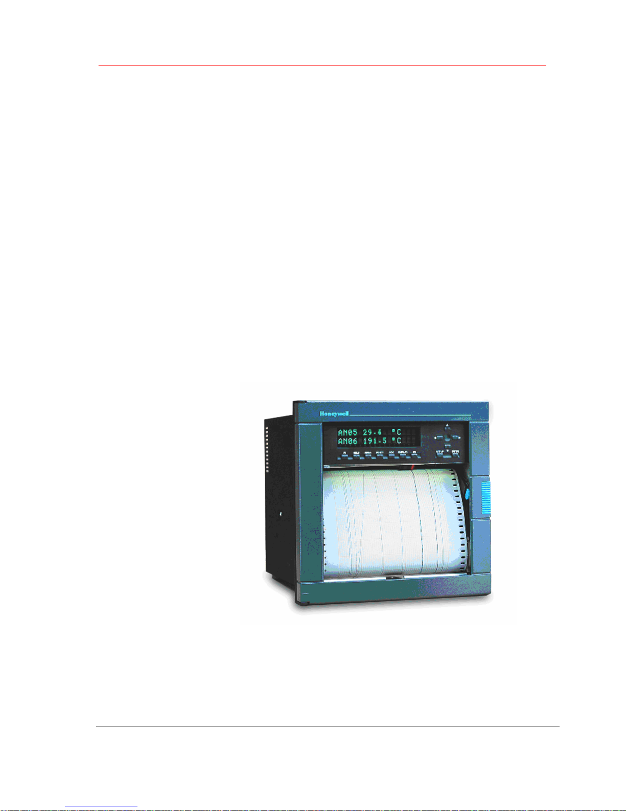
1. Turn off the power to isolate the recorder from the main supply.
2. Open the recorder door and remove the chart cassette from the chassis.
3. Turn OFF the switch. (See Figure 2-1)
Recorder's main power switch located behind the chart cassette
Figure 2-1
4. Remove the cover from the power supply terminal block. (See ref. E, Figure 2-15)
5. Disconnect the main supply from the power supply terminal block.
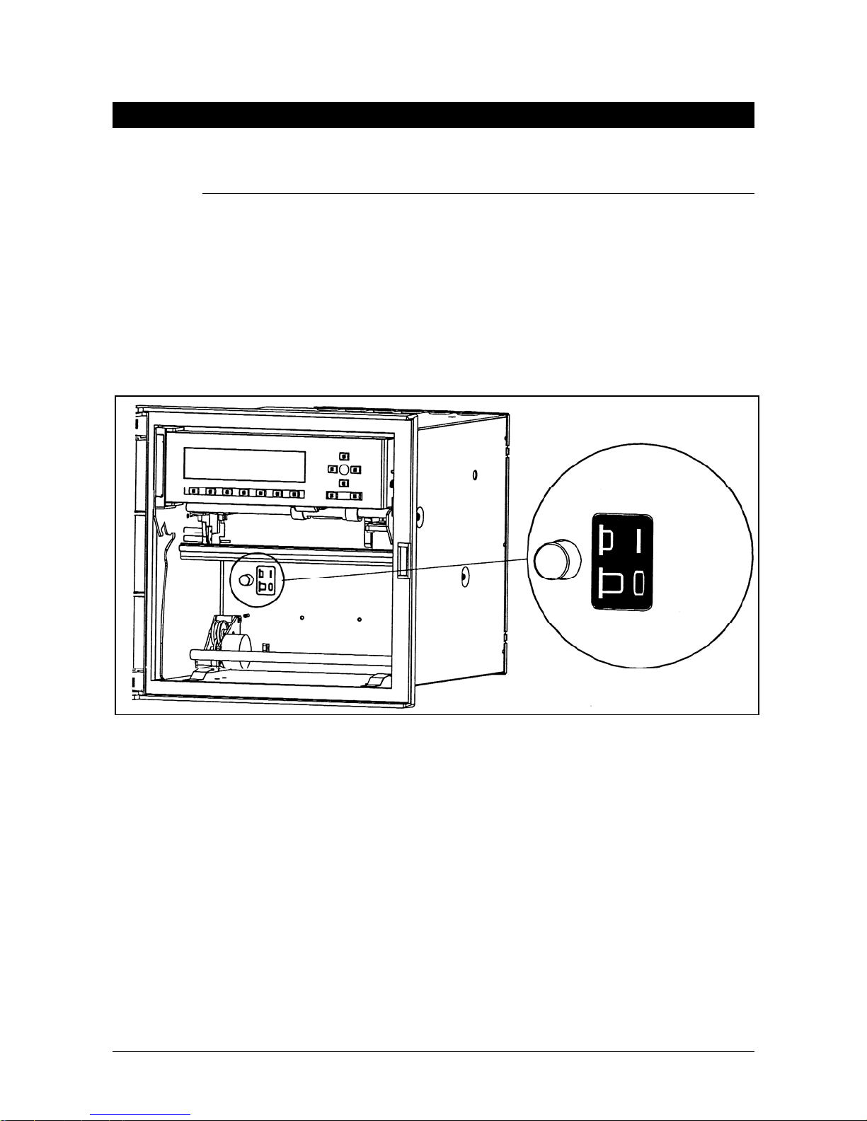
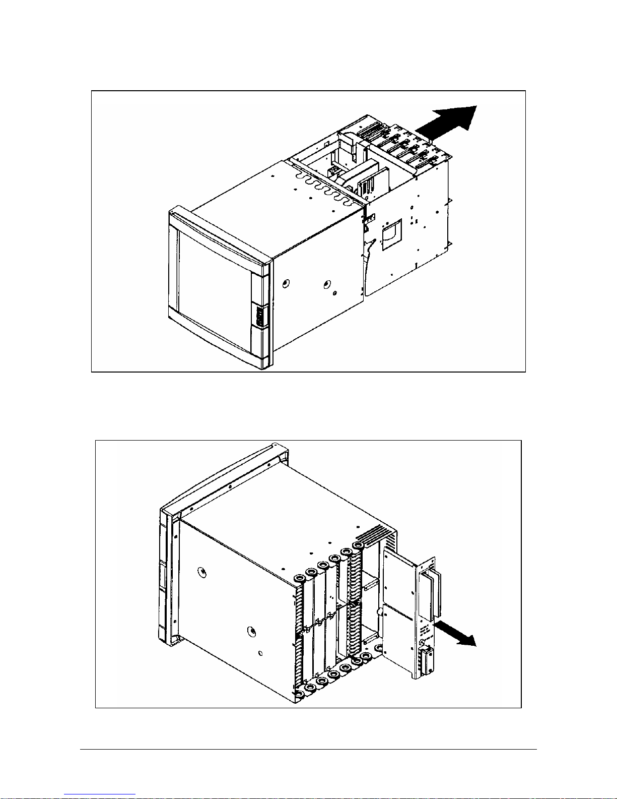
6. Unscrew the 3 fixing screws from the rear cover. (See ref. A, Figure 2-2)
7. Remove the rear cover. (See ref. B & C, Figure 2-2)
PCMCIA Option Manual 3
Page 8
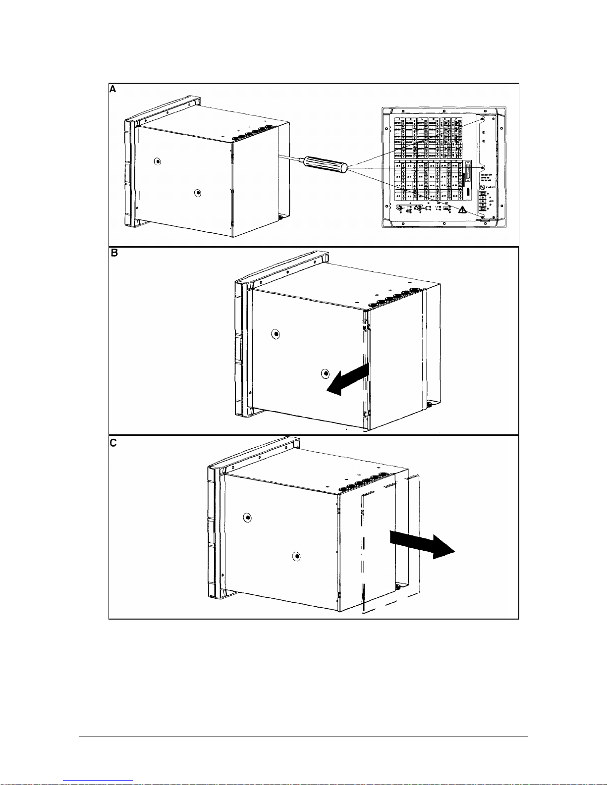
Figure 2-2
4 PCMCIA Option Manual
Page 9
8. Remove all the terminal blocks. (See Figure 2-3)
1) Press down on the terminal block clips.
2) Pull to release the terminal block.
Figure 2-3
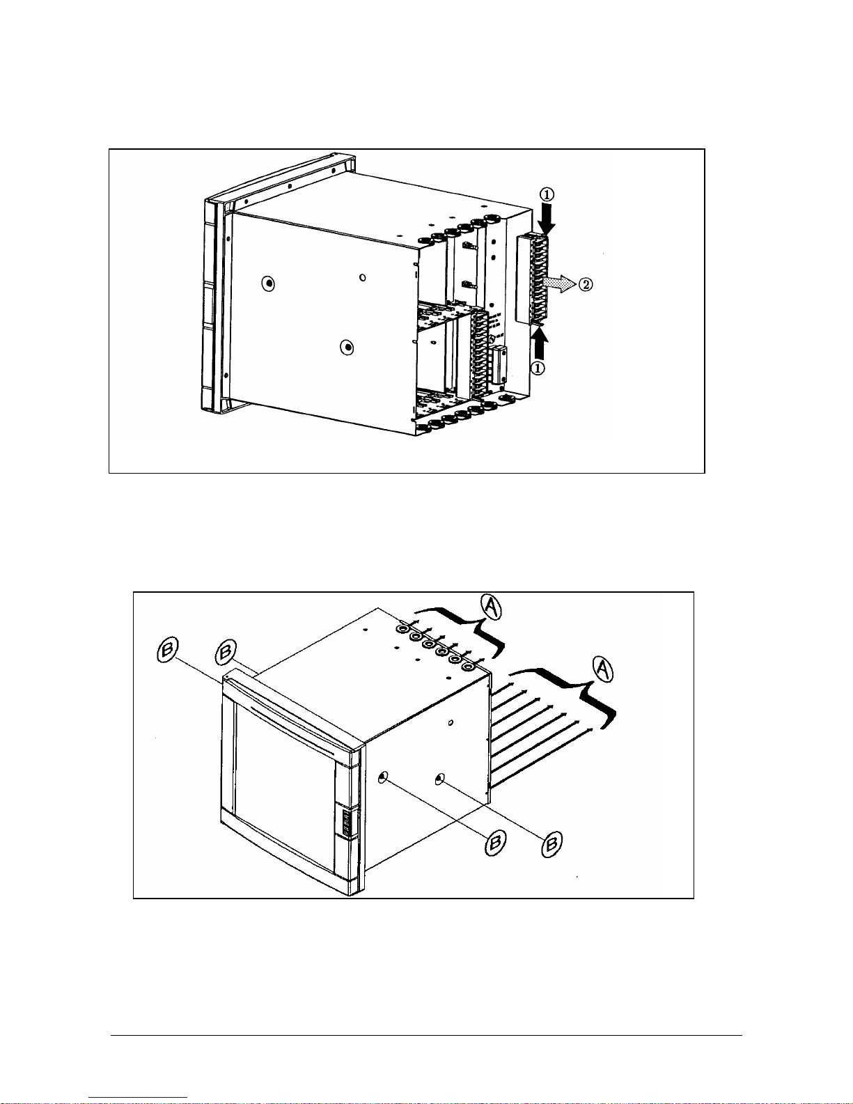
9. Remove all the grommets. (See ref. A, Figure 2-4)
10. Unscrew the 4 fixing screws (M4) and remove from the chassis with the Torx key T20.
(See ref. B, Figure 2-4)
Figure 2-4
PCMCIA Option Manual 5
Page 10
11. Slide the recorder chassis out of the case. (See Figure 2-5).
Figure 2-5
12. Unscrew the 2 fixing screws from the power supply.
13. Remove the power supply by removing 5 screws; two at the top, one in the middle and two at
the bottom. (See Figure 2-6)
Figure 2-6
6 PCMCIA Option Manual
Page 11
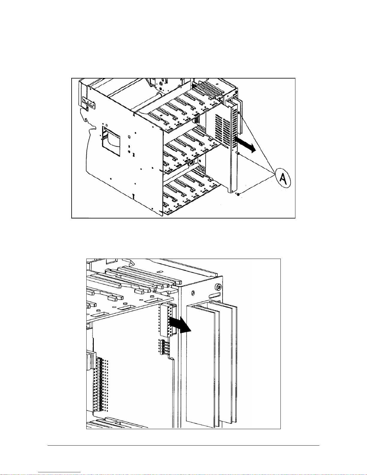
14. Remove the slot covers in the right hand side location, and the Communications card if
installed.
15. Remove the cover which protects the CPU board. Unscrew the 3 fixing screws. (See Figure 2-
7).
Figure 2-7
16. Ensure your antistatic ground strap is connected to earth before proceeding to avoid possible
electrostatic damage to the CPU board or PCMCIA board.
17. Disconnect the flat cable from the CPU board. (See Figure 2-8)
PCMCIA Option Manual 7
Page 12
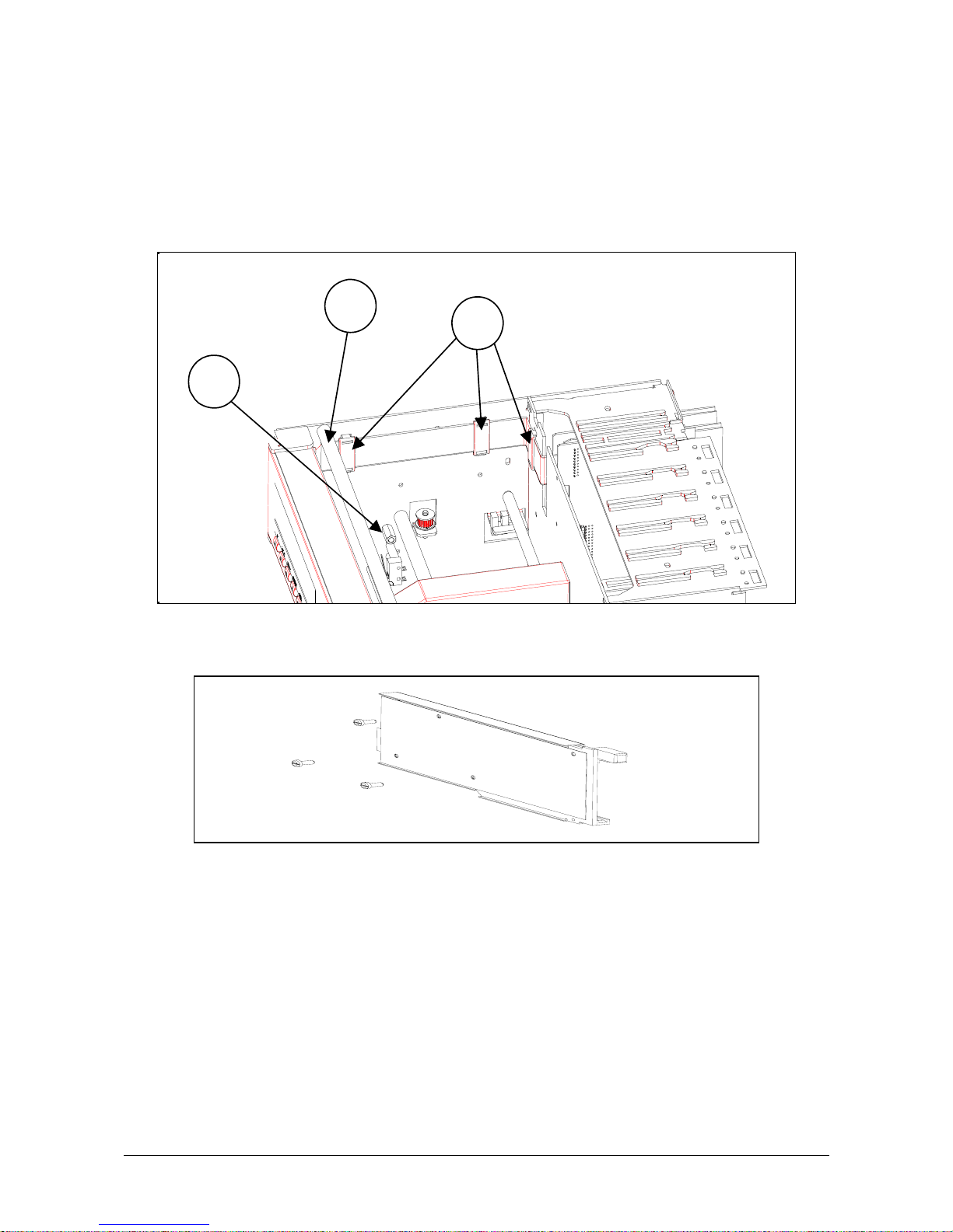
Figure 2-8
18. Remove the MMI flat cable plastic protection.
19. Remove the 3 flat cable clips. (See ref. A, Figure 2-9)
20. Remove the ink ribbon carriage stop (see ref. B standoff, Figure 2-9). Unscrew the fixing screw.
21. Remove the reinforcing bar (see ref. C, Figure 2-9) by unscrewing the 2 screws.
A
B
C
Figure 2-9
22. Unscrew the 3 fixing screws from the PCMCIA sub-assembly. (See Figure 2-10).
Figure 2-10
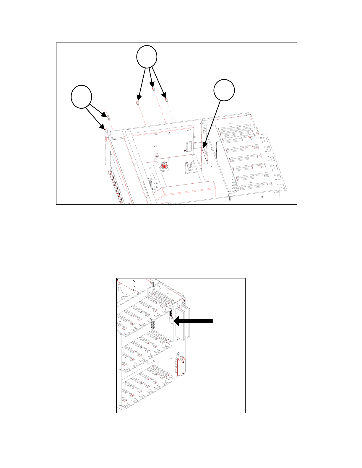
23. Remove the MMI with 2 screws (see B in Figure 2-11)
24. Put in place the PCMCIA sub-assembly on the left hand printer chassis side plate.
(See Figure 2-11)
25. Fix the PCMCIA sub-assembly with the 3 screws M3. (See ref. A, Figure 2-11) one from the
carriage stop.
WARNING: The 3 PCMCIA board fixing holes may have a wrong diameter (2.2 mm) but only on
the very first 180 mm units.
In this case, you have to enlarge them to 3+ 0.5/0 mm.
- Ins
ert fully your memory card (not supplied) in the card guides.
- Fix the memory card guides with the 2 screws M2. (See ref. B,
Figure 2-11) by reinstalling the
MMI.
8 PCMCIA Option Manual
Page 13
A
B
C
Figure 2-11
26. Reinstall reinforcing bar (see ref. C, Figure 2-9)
27. Pass the PCMCIA flat cable through the opening at the rear of the printer chassis.
- Fix the PCMCIA flat cable on the rear metal sheet with the double-side adhesive tape.
(See ref. C,
Figure 2-11). The adhesive tape is located on the flat cable.
- Ensure the printer carriage can move properly.
28. Replace the MMI flat cable plastic protection.
29. Connect the PCMCIA flat cable to the CPU board (see Figure 2-12). Ensure the connectors are
locat
ed correctly.
Figure 2-12
PCMCIA Option Manual 9
Page 14

30. Put in place the MMI flat cable on the PCMCIA cover.
31. Fix it with the 2 flat cable clips supplied (with foam). (See ref. A, Figure 2-13)
A
B
C
Figure 2-13
32. Ensure the MMI can open properly.
- Open the MMI fully.
- Remove the protection of the double-side adhesive tape located on the PCMCIA cover.
- Fix the MMI flat cable.
- Put in place the MMI flat cable at the rear of the PCMCIA cover. (See ref. C,
Figure 2-13)
33. Put in place the third MMI flat cable clip (not supplied) at the rear of the printer chassis.
(See ref. B, Figure 2-13).
34. Connect the MMI flat cable to the CPU Board (see Figure 2-14). Ensure the connectors are
locat
ed correctly.
10 PCMCIA Option Manual
Page 15

Figure 2-14
35. Replace the CPU board protection cover.
Replace the 3 fixing screws.
36. Replace the slot covers.
37. Replace the power supply. Replace the 2 rightest fixing screws.
38. Slide the recorder chassis back into the outer case.
39. Replace the 4 fixing screws (M4) with the Torx key T20. (See ref. B, Figure 2-4)
40. Replace all terminal blocks and grommets.
41. Replace the rear cover. Replace the 3 fixing screws. (See ref. A, Figure 2-2)
42. Reconnect the main supply to the power supply terminal block.
43. Replace the power supply terminal block cover. (See ref. E, Figure 2-15)
44. Turn ON the switch. (See Figure 2-1).
45. Replace the chart cassette.
46. Switch ON the main supply.
47. Upgrade your recorder firmware if the revision is lower than 001AK. (See CK 214).
PCMCIA Option Manual 11
Page 16

E
Figure 2-15
12 PCMCIA Option Manual
Page 17

PCMCIA Option Manual 13
3. OPERATION
3.1 Overview
3.1.1 PCMCIA card standard compatibility
The embeded PCMCIA driver supports all ATA flas
h card devices with a size from 2Mb up to 75Mb and
is compatible with the PC card format (type II).
The write-protected signal available
on these cards is not tested and not used because of a lack of
standard rules.
3.1.2 PCMCIA card handling
If your recorder is equipped with the PCMCIA option
board, you can use a memory card to store the
recorder information.
For this, proceed as indicated in the following figure to introduce the memory card:
Figure 3-1: Card loading in the 180mm or 250mm recorder
Note: The recorder will automatically detect the card presence.
The recorder indicates the writing status by lighting a led located un
der the display
(see Figure 3-2).
This led must be off when removing the memory card (this can be done with the remove or stop
function
), if not, some data may be lost.
To remove the memory card press the button located above it.
Page 18

14 PCMCIA Option Manual
PCMCIA
DISPLAY
RESET
F1
Figure 3-2: PCMCIA led in the 180mm or 250mm recorder
3.1.3 Archives summary
Archived data on a PCMCIA memory card may be:
• charts i.e an
alog inputs, math results or communication data,
• analo
g alarms,
• digital events,
• recorder ev
ents: (no paper, end of paper, burnout ...)
3.1.4 Recorder firmware compatibility
The PCMCIA option is compatible with the 001AK recorder firmware or higher. Older firmware
revisions will not allow your recorder to recognize the PCMCIA option board, the recorder will need to be
updated (see the OVERVIEW section of this manual).
3.2 SETUP
3.2.1 PCMCIA communication interface configuration
The PCMCIA option board is detected at power up during the recorder’s initialization time but, to be able
to use it, the INTERFACE parameter of the MISCELLANEOUS configuration matrix must be set to
PCMCIA.
The default configuration of this para
meter is JACK, which allows to configure the recorder with the PC
Configurator software.
When the option board has been detected, the PCMCIA co
nfiguration matrices (READ-WRITE, PRINT
CONF and SERVICE) appear and this option becomes TRUE in recorder’s hardware configuration (see
the CARD USED service in the MISCELLANEOUS matrix).
SUB-MATRIX PARAMETER CLASSIFICATION
MISCEL INTERFACE
♦♦♣♣
Definition:
Determines which of the PCMCIA option board or the JACK board is
con
nected to the recorder.
How to modify it:
Select a new value.
Possible choices: JACK
PCMCIA
Default value: JACK
Note:
This parameter cannot be modified by the PC Co
nfigurator software.
Note: The PCMCIA service functions are only available when the interface parameter is
set to PCMCIA.
HOLD
A
F2
A
CK
CTION
Page 19

PCMCIA Option Manual 15
3.2.2 PCMCIA card initialization
When using a memory card for the first time or when
changing the file structure of that memory card
(example: adding a file to it), it must be formatted by the recorder.
The recorder formats the memory card in a DOS compatible way and creates ALARMS, EVENTS and
DIAGNOSTIC files if need
ed, the remaining space is used to create the TREND files.
To archive TRENDS on the memory cards, the DESTINATION parameter of the READ-WRITE\CHART
matrix must b
e configured (see the chart configuration paragraph).
The storage frequency must also be programm
ed (see FREQUENCY parameter in the READ-
WRITE\PCMCIA matrix).
The INITIALIZATION service is located in SERVICE\PCMCIA matrix. During its
completion, "PCMCIA
INIT" will be displayed and the PCMCIA led will light ON.
Note: All the created files are empty at the initialization time.
3.2.3 PCMCIA card test
The recorder has an internal function that enables to test the memory card. This test takes about 1
minute pe
r Megabyte (4 minutes for a 4Mb memory card).
During the test the recorder checks the possibility to erase, writ
e and read the entire memory space.
Previous data are temporarily stored in a buffer and then re-writ
ten after the test so that this PCMCIA
TEST function can be done on DOS formatted cards or not.
In case of error, the PCMCIA status is set to PCMCI
A BAD, another status displayed means that the test
has succeeded. (Refer to PCMCIA status § 4.2.2).
During the test the PCMCIA led lights on indicating that data are
written on the card.
To stop this test at any time without da
maging the card, press the SETUP key.
For more details see the TEST function
in the PCMCIA\SERVICE matrix.
Note: Do not remove the card during the test function progress, this may damage the recorded data.
3.2.4 Charts selection
The TREND storage configuration is done in two steps:
;
Select TRACE choice in the TRACE parameter of the READ-WRITE\CHART matrix.
;
Select a value for the DESTINATION parameter, in the same matrix. See the following table:
SUB-MATRIX PARAMETER CLASSIFICATION
CHART DESTINATION
♦♦♣♣
Definition:
Determines where to print or c
opy charts.
How to modify it:
Select a new value.
Possible choices:
ON PAPER: trend
s are printed on paper only
ON FILE: trends are stored on PCMCIA only
PAPER & FILE: trends are both printed and stored in TRENDS file
Default value: ON PAPER
Note:
24 trends can be stored in the PCMCIA card TREND files with a 180
mm recorder.
32 trends can be stored in the PCMCIA card TREND files with a 250
mm recorder.
Page 20

16 PCMCIA Option Manual
3.3 Archive management
The archive management is detailed in the configuration chapter of this manual.
Archiving on the PCMCIA memory card may be conti
nuous or event driven depending on the START
condition (see § 4.1.3).
3.3.1 Continuous archiving
If the START parameter is configured to CONTINUOUSLY, the information are continuously stored on
the memory card.
However the archiving is stopped each time the mea
sures are stopped, this may happen when a
parameter of the configuration is changed or when a service function is running (all configuration or
service parameters with the "♦♦" classification stop the measures and so the archiving when they are
modified).
The archiving may also be stopped and restarted with the keybo
ard when the recording is continuous.
On the contrary, the recording may be started and stopped again if the START parameter is set to NO
ARCHIVE.
Note: At the begin
ning of the archiving, the alarms, the digital events and the recorder events which are
active are recorded in the corresponding file with a star (*), this to indicate that the event or the alarm
may be former to the recording date.
3.3.2 Event driven archiving
The recording may also be driven by a logic input or an alarm: an alarm on or a digital input closed to
start the recording and the same alarm off or the same logic input opened to stop it (see § 4.1.3)
As in the continuous archiving mode, the operator can start or stop the archiving
with the keyboard (see
§ 3.4).
The recorder continuously stores the alarms and events status
changes in an internal buffer. Therefore,
when the archiving starts, the recorder stores the latest alarm or event status change.
Consequently the alarm or event dates may be prior to the archiving start date.
Note:
When driving the archiving both with an event and with the keyboard, the latest action takes the
priority.
3.4 Keyboard archive management
The archive may be managed automatically, but in addition some actions may be done with the
keyboard.
3.4.1 START/STOP actions
By pressing the PRINT key it is possible to access to the "STOP ARCHIVE" or to the "START ARCHIVE"
action depending whether the archiving is running or not.
When the storage is in progress, the "STOP ARCHIVE" message will be displayed, otherwise the
"START ARCHIVE" message will be di
splayed.
The archiving can also be started or stopped by pressing F1 or F2 keys if the param
eters F1 KEY or F2
KEY in the READ-WRITE\MMI matrix are configured to "START/STOP ARCH".
3.4.2 RESET PCMCIA files
The way to erase the files content (to start a new a
rchive session) is to RESET the PCMCIA card by
pressing RESET key and selecting the RESET PCMCIA choice. This is also an easy way to initialize a
new PCMCIA card using.
Page 21

PCMCIA Option Manual 17
WARNING Î The RESET PCMCIA action will delete all the data stored on the card!
There is no backup done by the recorder. Information must be saved if needed with
an external PC by using a File manager for example.
3.4.3 REMOVE PCMCIA function
To prevent any loss of data when removing the memory card, the REMOVE PCMCIA function must be
used if the archiving is running (PCMCIA triangle lit ON).
The "REMOVE PCMCIA" action is accessible throug
h the PRINT key.
The "REMOVE PCMCIA" action is also accessible by pressin
g the F1 or F2 keys if the parameters F1
KEY or F2 KEY in the READ-WRITE\MMI matrix are configured to "REMOVE PCMCIA".
The system data is saved so that the card can be removed.
During this time, PCMCIA card status becomes CARD PENDI
NG and possible data will be stored in a
temporary buffer.
3.5 PCMCIA information
3.5.1 PCMCIA status
The recorder provides a memory card status (see § 4.2.2 STATUS service) to help in the card utilization.
This status may be one of the following cases:
Status Description Solution
PCMCIA MISSING * There is no PCMCIA memory card inside the recorder or the card
has not been detected.
Insert a compatible
PCMCIA memory card
PCMCIA NOT INIT***
Card has been recognized but it has not been initialized.
Initialize the memory card
(see § 4.2.2)
PCMCIA PENDING** Data cannot be stored on the PCMCIA card because the
configuration stored on it does not match the recorder
configuration or there is no memory card.
Insert a memory card,
Initializ
e it or reset it.(see §
4.2.2)
PCMCIA BAD*** Some data could not have been stored on PCMCIA because of a
physical problem on it.
Change the memory card
CARD PRESENT*
A PCMCIA card is present with no problem detected.
PCMCIA CONF CHG** There is a difference between the configuration of the recorder and
the parameters stored on the memory card, the parameters may
be one of the following: the Id number, the language, the trace, the
destination, the tagname and the engineering unit.
Restore the same
configuration on the
recorder or RESET the
memory card.
PCMCIA FULL*** One of the PCMCIA files is nearly full according to the EVENT
definition (see the "%FULL" parameter in § 4.1.3).
Remove the PCMCIA card
and save the files on your
computer.
Introduce it back and reset
it (see § 4.2.2).
PCMCIA DATA LOST**
This message is displayed if data to be written on the PCMCIA
card have not been stored and have been removed from the
internal buffer.
This appears when the recorder archivi
ng has started data and no
memory card is inserted for a long period.
See the PENDING case
* Information accessible through the STATUS service described in the paragraph 4.1.3.
** Information displayed in run mode, not visible with the STATUS service.
*** Information displayed in run mode and visible with the ST ATUS service.
Page 22

3.5.2 PCMCIA card status display
If PCMCIA card attribute is STORING, then a triangle appears. This means that any card removal could
cause data losses on the card.
PCMCIA
F1
HOLD
A
CTION
RESE
A
CK DISPLAY F2
This triangle is turned off during the recorder configuration.
"PCMCIA BAD", "PCMCIA NOT INIT", "PCMCIA FULL" or "P
CMCIA PENDING" could be displayed on
the lower display as blinking message, depending on the corresponding status.
Note: The PCMCIA led must be lit on, for the recorder to be able to store data on the PCMCIA card.
3.5.3 PCMCIA event
The PCMCIA EVENT located in the READ-WRITE\EVENTS matrix (refer to the product manual) is
activated if the PCMCIA card or the driver is in one of the following conditions:
MESSAGE
DISPLAYED
DESCRIPTION SOLUTION
PCMCIA NOT INIT
The card has not been initialized by the recorder. Initialize the memory card.
PCMCIA BAD
There is a failure in the card device. Change the memory card.
PCMCIA FULL At least one archive file (TRENDS, ALARMS, EVENTS or
DIAGNOSTIC) has reached the user-defined %full threshold
(see the % FULL parameter in the READ-WRITE\PCMCIA
matrix).
Save the files on your computer
and reset the memory card (see
§ 4.2.2).
Note: When the PCMCIA FULL message is displayed, the recording continues till the 100% full is
reached then all additional informations to this file are lost except if the ROLLOVER option is set (see §
4.1.3). Other files continue to be normally updated.
3.6 PCMCIA file descriptions
All PCMCIA card files are PC-compatible and are readable by the TrendManager Software package.
3.6.1 File name conventions
PCMCIA files have a fixed extension according to their content: TRENDS (*.LNT), ALARMS (*.LNA),
EVENTS (*.LNE) and DIAGNOSTICS (*.LND).
The content of each type of file is:
• .LNT files co
ntain CHARTS records
• .LNA
files contain ALARMS records (all analog alarms)
• .LNE files co
ntain DIGITAL events records
• .LND
files contain recorder EVENTS records.
The recorder stores data depending on i
ts configuration: TRENDS (charts channels records)
informations are sent to the PCMCIA driver at user-defined frequency, ALARMS (alarms records),
EVENTS (digital events records) and DIAGNOSTIC (recorder events records) are asynchronous
informations and so, are sent at each occurrence.
18 PCMCIA Opti
on Manual
Page 23

3.6.2 Import data to the TrendManger software
The TrendManager Software Suite has a built in Data Conversio
n Tool that will accurately reproduce
data from the Honeywell VRX recorder range
The data is imported from the device media using the TrendManager Pro Software Suite Import function
into the datab
ase.
Select the Import button from the main tool bar a
nd the External import box will appear.
Select the data option and select From Dire
ctory as the source location.
Use the Change button to browse your PC or network to locate the data.
Press the Import button when the correct location has been selected.
PCMCIA Opti
on Manual 19
Page 24

The User Acknowledgement box will appear; to proceed this mu
st be acknowledged.
Select to import data to a New or Existing device. For an Existing
device the Importing Controller box will
display the existing devices in the TMP databases.
Select the device you wish to import the data from and click on
Next. This will start the data importing.
20 PCMCIA Opti
on Manual
Page 25

If the data is for a New device, a list of device types
will appear, select one and go to Next.
Enter a device name and description and click on OK.
Next choose the format type for the importing data. Th
e two different formats are:
X Series (recommended) - This has the benefit of flexible pen
scale limits that can be changed at any
time in the X Series release of TrendServer. Data imported in this format cannot be loaded into a version
5 release of TrendServer.
Version 5 - Pen scale limits will be fixed once set, and any data values imported outside of the pen scale
limits will be cappe
d at the appropriate limit. However, this data can be read in by version 5 release of
TrendServer. Click on OK and the data will start to import.
If there is a device in the database with the same Se
rial number but a different ID, this will be flagged up
and you can choose to add the data to this device or a new device will be created. For a new device
choose from the Database Device Destination User Selection box.
PCMCIA Opti
on Manual 21
Page 26

The Data File conversion will start and the destination
box will appear to confirm the correct device.
When the file conversion is complete press ok.
When the import is complete the data will be automatically displayed as a grap
h showing the data as pen
traces and displaying each associated pen. Any events will be imported (via Trendbus only) with the data
and can be displayed on the graph using the Event button at the bottom of the graph.
The device is loaded into the recorders list for identification purpo
ses, click on the Recorders icon to
display the list of recorders. The device can not be configured from the software. The imported data can
be graphed, analyzed, archived, printed and exported to a spread sheet.
For data imported from Honeywell V5, X Series recorders, an Event viewer is available by right clicking
on the re
corder in the recorders list and selecting Events.
Refer to the TrendManager Pro Software Suite manual
43-TV-25-11 for further information.
Available at www.honeywell.com/ps
22 PCMCIA Option Manual
Page 27

PCMCIA Option Manual 23
4. PCMCIA CONFIGURATION
4.1 PCMCIA sub-matrix parameters
4.1.1 PCMCIA sub-matrix parameters list
SUB-MATRIX
PCMCIA READ/WRITE
Position of
parameters
START page 23
ROLLOVER page 24
LOG FREQ page 24
% FULL page 24
4.1.2 Explanation of the classification
This section will describe all the matrices that have been modified by the PCMCIA option and then, how
configuration will be possible.
♦
Means that parameter can be modified in RUN mode (measures are still done)
♦♦
Means that parameter can be modified in STOP mode (measures are stopped)
♣
Means that parameter can be modified with password 1 or password 2
♣♣
Means that parameter can be modified with password 2 only
4.1.3 PCMCIA sub-matrix parameters description
SUB-MATRIX PARAMETER CLASSIFICATION
PCMCIA
START
♦♦♣♣
Definition:
Automatic start conditions
How to modify it:
Select a new start condition
Possible choices: NO ARCHIVE
CONTINUOUSLY
DI CLOSED #
AL ON #
Default value: NO ARCHIVE
Note:
Stop conditions are the following:
DI OPENED #
AL OFF #
Page 28

24 PCMCIA Option Manual
SUB-MATRIX PARAMETER CLASSIFICATION
PCMCIA
ROLLOVER
♦♦♣♣
Definition:
Determines if, once the end of archive file has b
een reached, new data
are copied at the beginning of this file, so that it contains the most
recent data, or not.
How to modify it:
Select or not rollover mode
Possible choices: DISABLE
ENABLE
Default value: DISABLE
SUB-MATRIX PARAMETER CLASSIFICATION
PCMCIA
LOG FREQ
♦♦♣♣
Definition:
Archive frequency used to log TRENDS files.
How to modify it:
Select a new frequency.
Possible choices: 1 s
5 s
10 s
15 s
30 s
1 mn
5 mn
10 mn
15 mn
30 mn
Default value: 10 s
Note:
In case of a change in the login frequency on the same file, the SDA
software will
make interpolations (depending if that option is configured
or not) to produce a trend at the highest frequency.
It is recommended in that case to read the file without interpolation.
SUB-MATRIX PARAMETER CLASSIFICATION
PCMCIA
% FULL
♦♣
Definition:
Determines PCMCIA EVENT threshold.
How to modify it:
Select a threshold in %.
Possible choices: 0 to 100%
Default value: 90% *
See also:
PCMCIA in EVENTS matrix
* The default value is 0% if the recorder was previousl
y equipped with a firmware revision older than 001AK.
Page 29

4.2 PCMCIA sub-matrix services
4.2.1 PCMCIA sub-matrix services list
SUB-MATRIX
PCMCIA SERVICES
Position of
parameters
INITIALIZATION page 26
TEST page 26
SOFTWARE page 27
SIZE page 27
STATUS page 27
DIRECTORY page 28
NOTE: The
memory card must be present in the recorder in order to access to the service functions and the
INTERFACE parameter must be set to PCMCIA.
PCMCIA Opti
on Manual 25
Page 30

26 PCMCIA Option Manual
4.2.2 PCMCIA sub-matrix services description
SUB-MATRIX PARAMETER CLASSIFICATION
PCMCIA
INITIALIZATION
♦♦♣♣
Definition:
Formats and initializes PCMCIA board.
How to use/execute it:
At first, you have to enter the number of reco
rds you want for ALARMS files:
"Nb ALARM REC ?" is bli
nking and you can type it (1651 max).
Then their file name (7 characters max.):
"ALARM NAME ?" is blinking and you can type it .
Then the number of records for EVENTS files:
"Nb EVENT REC ?" is bli
nking and you can type it (1651 max).
Then its file name (7 characters max.):
"EVENT NAME ?" is blinking and you can type it.
The number of records for DIAGNOSTIC files:
"Nb DIAG REC ?" is blinking and you can type it (2667 max).
Then its file name (7 characters max.):
"DIAG NAME ?" is blinki
ng and you can type it.
And finally, we have to type TRENDS file names (7 characters max.) :
"TREND NAME ?" is blinking a
nd you can type it.
During completion, "PCMCIA INIT" is displayed.
Notes:
•
At each step, you can abort this initialization by pressing
SET UP key.
•
Default file names are "ALARM" for ALARM, "EVENT" for EVENT, and "DIAG"
for DIAGNOSTIC and their extensions are automatically added. If another file
name has been entered, then it takes the place of the default one for the
following answers.
•
A digital index is automatically added to trend file names on PCMCIA card.
•
ALARM, EVENT and DIAG records are organized in blocks and the files use
sectors of 512 bytes (as in the DOS) so that the effective number of records may
be greater than the programmed number of records.
•
If the number of records is set to "0", the corresponding file is not created.
SUB-MATRIX PARAMETER CLASSIFICATION
PCMCIA
TEST
♦♦♣♣
Definition:
Tests PCMCIA device.
How to use/execute it:
By pressing ENTER, PCMCIA board driver te
sts the whole PCMCIA device: during
execution, the percentage of test completion is displayed on the screen:
For example: "15% PASSED"
If an error occurs during this test, "FAILED" appe
ars during 2s. Test is aborted and
PCMCIA status becomes PCMCIA BAD.
Note:
At any moment, you can abort the process by usin
g SETUP key.
The test duration is about 1 minute per Megabyte of capacity.
Page 31

PCMCIA Option Manual 27
SUB-MATRIX PARAMETER CLASSIFICATION
PCMCIA
SOFTWARE
♦♣
Definition:
PCMCIA board driver s
oftware revision.
How to use/execute it:
You can only read the value.
You can exit by pressing SETUP key.
SUB-MATRIX PARAMETER CLASSIFICATION
PCMCIA
SIZE
♦♣
Definition:
PCMCIA board size in Mb.
How to use/execute it:
You can only read the value.
You can exit by pressing SETUP key.
SUB-MATRIX PARAMETER CLASSIFICATION
PCMCIA
STATUS
♦♣
Definition:
Return status of PCMCIA board.
PCMCIA board status could be:
PCMCIA MISSING: the card is not inboard
PCMCIA NOT INIT: the c
ard has to be initialized (cf INITIALIZATION
parameter in this matrix)
PCMCIA BAD: the ca
rd cannot be correctly used by the PCMCIA driver.
Initialize it again or test it.
PCMCIA FULL: at least, one of the incl
uded file is full according to the
threshold configured by the user (cf "%FULL" parameter in
READ/WRITE PCMCIA matrix.
PCMCIA PRESENT: the card is
ready to be used
How to use/execute it:
You can only read the status.
You can exit by using SETUP key.
Page 32

28 PCMCIA Option Manual
SUB-MATRIX PARAMETER CLASSIFICATION
PCMCIA
DIRECTORY
♦♣
Definition:
Allows you to read PCMCIA card directory: the name
s of the files on the
memory card (with DOS extension), the number of records used and
remaining per file are displayed (only the files compatible with the recorder
data are displayed).
How to use/execute it:
If a file exists, its name and its index are
first displayed in the PCMCIA card:
Ex
: 01 ALARM.LNA
With the Ï a
nd Ð keys, you can scroll all SDA files written on the card.
The Í and Î keys allow you to display the number of records already
used in this file and the number of remaining records. The file index is still
displayed to show you which is the corresponding file.
Ex
: Press Î. Then the following message appears on the display:
01 U: 12
That means that 12 records have alread
y been written on the 1st file.
Press Î again: The following string is shown:
01 R: 1
488
That means that 1488 records are still available for this 1st file.
Or the following string is shown for TREND files:
01 R : 1 10 : 45
That means that there is still space for 1
day 10 hours and 45 minutes of
archiving time.
Note that except for TREND files, the total numbe
r of records corresponds
to the size given or computed during PCMCIA card initialization.
You can exit by using SETUP key.
Page 33

PCMCIA Option Manual
29
5. KITS LIST
KITS LIST PART #
PCMCIA upgrade kit 46190163-501
Compact Flash Card 256MB 50001011-504
Compact Flash to PCMCIA Adapter 50001014-501
TrendManager Analysis software 50016133-501
Page 34

PCMCIA Option Manual
30
Page 35

PCMCIA Option Manual
31
6. TROUBLESHOOTING
6.1 PCMCIA option is not recognized by the recorder (PCMCIA matrix does
not appear)
CHECK DIAGNOSTIC / ACTION
Check if the flat cable connection
betwe
en PCMCIA board and CPU
board is correct.
1. NO: Check for the proper connection.
6.2 PCMCIA INIT service is not possible
CHECK DIAGNOSTIC / ACTION
Is PCMCIA memory card really
plugg
ed into the driver?
1. NO: Insert the card into the board.
Is problem corrected ? 2. NO: Ve
rify you only use ATA flash card devices (see
Section 5 - Kits list for certified cards).
6.3 “PCMCIA FULL” message is displayed on the recorder
CHECK DIAGNOSTIC / ACTION
What is the threshold value in READWRITE\PCMCIA matrix?
1. Incre
ase this value to disable “PCMCIA FULL” message
display.
Is problem corrected ? 2. NO: Initiali
ze PCMCIA card again with INIT utility in
PCMCIA / SERVICE matrix and increase the number of
records for the files which are too small.
6.4 “PCMCIA NOT INIT” message is displayed on the recorder
CHECK DIAGNOSTIC / ACTION
1. Initialize the card by usi
ng INIT menu in
PCMCIA / SERVICE matrix.
6.5 “PCMCIA BAD” message is displayed on the recorder
CHECK DIAGNOSTIC / ACTION
Is the card readable by an external
driver?
1. NO: Chan
ge the card.
2. YES: Run a TEST (PCMCIA / SERVICE).
- If the test is successful, then the ca
rd is OK.
- If the test stops before reaching 100 % of completion then
an are
a of the card is bad. The card has to be changed.
Page 36

PCMCIA Option Manual
32
6.6 “PCMCIA PENDING” message is displayed on the recorder
CHECK DIAGNOSTIC / ACTION
Check the PCMCIA STATUS in
PCMCIA / SERVICE :
PCMCIA MISSING
The archive is ON and no card has been inserted in the
driver. Insert
a card to turn off the display.
PCMCIA BAD
The archive is ON and the inserted card is bad. Refer to §
6.
5 to check card validity or insert a valid card.
PCMCIA NOT INIT
The archive is ON and the inserted card is not initialized.
Refer to § 6.4.
PCMCIA PRESENT
The card has been initialized but part of the archiving
config
uration stored on the card does not match with the
configuration of the recorder. Press RESET key and select
RESET PCMCIA menu to make both configurations match.
WARNING Î A RESET
PCMCIA will erase all previous
data stored on the card.
6.7 PCMCIA triangle does not appear on the display when archiving
CHECK DIAGNOSTIC / ACTION
Check INTERFACE parameter in
MISCELLANEOUS / Read
/Write
Turn parameter to PCMCIA.
Check START parameter in
PCMCIA / Read/Write
If the archive is triggered by an alarm or a digital status,
che
ck alarm or digital status which should start the
archiving (Press the DISPLAY key and select ALARM
STATUS or LOGIC STATES).
Is PCMCIA PENDING displayed
on the MMI ?
Refer to § 6.6
6.8 No data have been written on the card
CHECK DIAGNOSTIC / ACTION
Check START parameter in
PCMCIA / Read/Write
The archiving start condition has not been met. No data
have bee
n stored on the card.
Was PCMCIA PENDING displayed
on the MMI ?
Refer to § 6.6
Check ROLLOVER parameter in
PCMCIA / Read/Write
If ROLLOVER is set on DISABLE, check in DIRECTORY
(PCM
CIA / SERVICE) the amount of records that it is still
possible to store. If this amount is 0, no data will be
recorded on this file. Turn ROLLOVER to ENABLE or
either reset or initialize the card.
Page 37

PCMCIA Option Manual
33
6.9 SDA generates an error while opening trend files in chart display
CHECK DIAGNOSTIC / ACTION
1. An archive
d Math function has returned an error code
which prevents SDA from charting correctly this channel.
Open the trend file in the data table format and note the
math in error. Open the trend file in the trend format and
remove the math function in error from the list of selected
traces to be charted.
2. When the
archiving process is incorrectly interrupted (ie :
power off while archiving), it may happen that SDA displays
an error message while opening the archive files. Files are
nevertheless still readable except for their last data part. It is
then recommended in that case to reduce the last time to
display in the SDA opening trend files window.
Page 38

PCMCIA Option Manual
34
Page 39

PCMCIA Option Manual
35
7. PROMPTS TRANSLATION
EN FR GE SP IT
PCMCIA PCMCIA PCMCIA PCMCIA PCMCIA
CONFIRM CONFIRMER BESTÄTIGEN CONFIRM CONFERMA
PARAMETERS
START DEMARRAGE START EMPEZAR PARTENZA
R0LLOVER RE-ENRG UEBERSCHR VUELTA RICARICARE
LOG FREQ FREQ ENRG FREQ AUFZ FREC LOG FREQ LOG
% FULL % PLEIN % VOLL % LLENO % PIENO
INIT INIT INIT INICIALIZ INITIALIZZA
TEST TEST TEST PRUEBA TEST
SOFTWARE LOGICIEL SOFTWARE SOFTWARE SOFTWARE
SIZE TAILLE GROESSE TAMANO DIMENSIONE
STATUS ETAT STATUS ESTADO STATO
DIRECTORY REPERTOIRE VERZEICHNIS REPERTORIO DIRECTORY
POSSIBLE VALUES
NO ARCHIVE PAS ARCHIVE KEIN ARCHIV NO ARCHIVO NO ARCHIVIO
AL ON # AL ON N° AL EIN NR AL ACTIV # ALL ON#
DI CLOSED# LO FER N° BI SCHL NR ED CERRA # DI CHIUSO#
CONTINUOUSLY CONTINU DAUERND CONTINUAMENT CONTINUO
NB ALARM REC? NB PTS ALARME ? ANZ REG ALARM N REG ALARMAS ? N PUNTI ALLARME
ENABLE AUTORISE AKTIVIEREN ACTIVAR ABILITATO
DISABLE REFUSE INAKTIVIEREN DEACTIVAR DISABILITATO
ALARM NAME? NOM ALARME ? ALARM BEZEICHNG NOMBRE ALARMA ? NOME ALLARMI
NB EVENT REC? NB PTS EVT ? ANZ REG EREIGN N REG EVENTOS ? N PUNTI EVENTI
EVENT NAME NOM EVT ? EREIGN BEZEICHNG NOMBRE EVENTO ? NOME EVENTI
NB DIAG REC? NB PTS DIAG ? ANZ REG DIAGR N REG DIAG ? N PUNTI DIAG
DIAG NAME NOM DIAG ? DIAGR BEZEICHNG NOMBRE DIAG ? NOME DIAG
TREND NAME NOM TRACE ? TREND BEZEICHNG NOMBRE TRAZA ? NOME TRACCE
% PASSED % TEST BON % ERFOLG % BUENA % TEST BUONO
FAILED ECHEC FEHLERHAFT MALA NO RIUSCITO
PCMCIA BAD PCMCIA MAUVAISE PCMCIA AUSFALL PCMCIA DEFEC PCMCIA GUASTA
PCMCIA FULL PCMCIA PLEINE PCMCIA VOLL PCMCIA LLENA PCMCIA PIENA
PCMCIA NOT INIT PCMCIA NON INIT PCMCIA NICHT INI PCMCIA SIN INIC PCMCIA NON INIZ
PCMCIA PENDING PCMCIA EN ATT. PCMCIA WARTEZUST PCMCIA PENDIENTE PCMCIA IN ATTESA
PCMCIA DATA
LOST
PERTE DE DONNEES VERLOR DATEN DATOS PERDIDOS DATI PERSI
PCMCIA PRESENT PCMCIA PRESENTE PCMCIA VORHANDEN PCMCIA PRESENTE PCMCIA PRESENTE
PCMCIA MISSING PCMCIA ABSENTE PCMCIA VERREIST PCMCIA SACADA PCMCIA ASSENTE
REMOVE PCMCIA RETIRER PCMCIA ENTFERNE PCMCIA QUITAR PCMCIA TOGLIERE PCMCIA
RESET PCMCIA RAZ PCMCIA PCMCIA ZURUECKS REINICIAR PCMCIA RESET PCMCIA
PCMCIA INIT INIT PCMCIA INIT PCMCIA INIC PCMCIA INIZIALIZ PCMCIA
Mb Mo MB Mb MB
PCMCIA CONF
CHG
PCMCIA CHGT CONF PCMCIA KONFÄNDRG CAMB CONF
PCMCIA
CAMB CONF
PCMCIA
START ARCHIVE DEBUT ARCHIVE START ARCHIVIERG INICIAR ARCHIVO START ARCHIVIO
STOP ARCHIVE FIN ARCHIVE STOP ARCHIVIERG PARAR ARCHIVO STOP ARCHIVIO
PCMCIA EVENT EVT PCMCIA PCMCIA EREIG SUC PCMCIA EVEN PCMCIA
WAIT PLEASE ATTENDEZ SVP BITTE WARTEN ESPERE P. FAVOR ATTENDERE
INTERFACE INTERFACE INTERFACE INTERFASE INTERFACCIA
s s SEKUNDE
SEKUNDEN
s s
mn mn MINUTE
MINUTEN
mn mn
Page 40

PCMCIA Option Manual
36
Page 41

Page 42

Sales and Service
For application assistance, current specifications, pricing, or name of the nearest Authorized Distributor,
contact one of the offices below.
ARGENTINA
Honeywell S.A.I.C.
Belgrano 1156
Buenos Aires
Argentina
Tel. : 54 1 383 9290
ASIA PACIFIC
Honeywell Asia
Pacific Inc.
Room 3213-3225
Sun Kung Kai Centre
N° 30 Harbour Road
Wanchai
Hong Kong
Tel. : 852 829 82 98
AUSTRALIA
Honeywell Limited
5 Thomas Holt Drive
North Ryde Sydney
Nsw Australia 2113
Tel. : 61 2 353 7000
AUSTRIA
Honeywell Austria
G.M.B.H.
Handelskai 388
A1020 Vienna
Austria
Tel. : 43 1 727 800
BELGIUM
Honeywell S.A.
3 Avenue De Bourget
B-1140 Brussels
Belgium
Tel. : 32 2 728 27 11
BRAZIL
HONEYWELL DO
Brazil
And Cia
Rua Jose Alves Da
Chunha
Lima 172
Butanta
05360.050 Sao Paulo
Sp
Brazil
Tel. : 55 11 819 3755
BULGARIA
HONEYWELL EOOD
14, Iskarsko Chausse
POB 79
BG- 1592 Sofia
BULGARIA
Tel : 359-791512/
794027/ 792198
CANADA
Honeywell Limited
The Honeywell Centre
300 Yorkland Blvd.
Toronto, Ontario
M2j 1s1
Canada
Tel.: 800 461 0013
Fax:: 416 502 5001
CZECH REPUBLIC
HONEYWELL,
Spol.S
.R.O.
Budejovicka 1
140 21 Prague 4
Czech Republic
Tel. : 42 2 6112 3434
DENMARK
HONEYWELL A/S
Automatikvej 1
DK 2860 Soeborg
DENMARK
Tel. : 45 39 55 56 58
FINLAND
HONEYWELL OY
Ruukintie 8
FIN-02320 ESPOO 32
FINLAND
Tel. : 358 0 3480101
FRANCE
HONEYWELL S.A.
Bâtiment « le Mercury »
Parc Technologique de St
Aubin
Route de l’Orme
(CD 128)
91190 SAINT-AUBIN
FRANCE
Tel. from France:
01 60 19 80 00
From other countries:
33 1 60 19 80 00
GERMANY
HONEYWELL AG
Kaiserleistrasse 39
D-63067 OFFENBACH
GERMANY
Tel. : 49 69 80 64444
HUNGARY
HONEYWELL Kft
Gogol u 13
H-1133 BUDAPEST
HUNGARY
Tel. : 36 1 451 43 00
ICELAND
HONEYWELL
Hataekni .hf
Armuli 26
PO Box 8336
128 reykjavik
Iceland
Tel : 354 588 5000
ITALY
HONEYWELL S.p.A.
Via P. Gobetti, 2/b
20063 Cernusco Sul
Naviglio
ITALY
Tel. : 39 02 92146 1
MEXICO
HONEYWELL S.A. DE
CV
AV. CONSTITUYENTES
900
COL. LOMAS ALTAS
11950 MEXICO CITY
MEXICO
Tel : 52 5 259 1966
THE NETHERLANDS
HONEYWELL BV
Laaderhoogtweg 18
1101 EA AMSTERDAM
ZO
THE NETHERLANDS
Tel : 31 20 56 56 911
NORWAY
HONEYWELL A/S
Askerveien 61
PO Box 263
N-1371 ASKER
NORWAY
Tel. : 47 66 76 20 00
POLAND
HONEYWELL Sp.z.o.o
UI Domaniewska 41
02-672 WARSAW
POLAND
Tel. : 48 22 606 09 00
PORTUGAL
HONEYWELL
PORTUGAL LDA
Edificio Suecia II
Av. do Forte nr 3 - Piso 3
2795 CARNAXIDE
PORTUGAL
Tel. : 351 1 424 50 00
REPUBLIC OF IRELAND
HONEYWELL
Unit 1
Robinhood Business
Park
Robinhood Road
DUBLIN 22
Republic of Ireland
Tel. : 353 1 4565944
REPUBLIC OF
SINGAPORE
HONEYWELL PTE LTD
BLOCK 750E CHAI
CHEE ROAD
06-01 CHAI CHEE IND.PARK
1646 SINGAPORE
REP. OF SINGAPORE
Tel. : 65 2490 100
REPUBLIC OF SOUTH
AFRICA
HONEYWELL
Southern Africa
PO BOX 138
Milnerton 7435
REPUBLIC OF SOUTH
AFRICA
Tel. : 27 11 805 12 01
ROMANIA
HONEYWELL Of
fice
Bucharest
147 Aurel Vlaicu Str.,
Sc.Z.,
Apt 61/62
R-72921 Bucharest
ROMANIA
Tel : 40-1 211 00 76/
211 79
RUSSIA
HONEYWELL INC
4 th Floor Administrative
Builiding of AO "Luzhniki"
Management
24 Luzhniki
119048 Moscow
RUSSIA
Tel : 7 095 796 98 00/01
SLOVAKIA
HONEYWELL Ltd
Mlynske nivy 73
PO Box 75
820 07 BRATISLAVA 27
SLOVAKIA
Tel. : 421 7 52 47 400/425
SPAIN
HONEYWELL S.A
Factory
Josefa Valcarcel, 24
28027 MADRID
SPAIN
Tel. : 34 91 31 3 61 00
SWEDEN
HONEYWELL A.B.
S-127 86 Skarholmen
STOCKHOLM
SWEDEN
Tel. : 46 8 775 55 00
SWITZERLAND
HONEYWELL A.G.
Hertistrasse 2
8304 WALLISELLEN
SWITZERLAND
Tel. : 41 1 831 02 71
TURKEY
HONEYWELL A.S.
Caryiryolu Sok No. 7
Ucgen Plaza, Kat 5-6-7
Icerenkoy 81120
Instanbu
l
Turkey
Tel (90-216) 575 66 00
UNITED KINGDOM
HONEYWELL
Honeywell House
Arlington Business Park
Bracknell,
Berkshire
RG12 1EB
Tel: +44 (0) 1344 656000
U.S.A.
HONEYWELL
PROCESS SOLUTIONS
512 Virginia Drive
Ft. Washington Pa 19034
U.S.A.
Tel. : +1 215-641-4300
VENEZUELA
HONEYWELL CA
APARTADO 61314
1060 CARACAS
VENEZUELA
Tel. : 58 2 239 0211
Honeywell Field Solutions
2500 W. Union Hills Dr.
Phoe
nix, AZ 85027
Tel: 877.466.3993 or 602.313.6665
www.honeywell.com/ps
EN1I-6208
May 2008
© 2008 Honeywell International Inc.
 Loading...