

Page 1

DPR 100 C - DPR 100 D
PRODUCT MANUAL
Page 2

DPR 100 C - DPR 100 D
PRODUCT MANUAL
Ref. : US1I-6137
Issue :19 October, 2003
Page 3

Copyright, Notices, and Trademarks
© Copyright 2000 by Honeywell Inc.
While this information is presented in good faith and believed to be
accurate, Honeywell disclaims the implied warranties of
merchantability and fitness for a particular purpose and makes no
express warranties except as may be stated in its written agreement
with and for its customer.
In no event is Honeywell liable to anyone for any indirect, special or
consequential damages. The information and specifications in this
document are subject to change without notice.
This document was prepared using Information Mapping
methodologies and formatting principles.
Information Mapping is a trademark of Information Mapping Inc.
Windows is a registered trademark of Microsoft Inc.
Modbus is a registered trademark of MODICON, Inc.
The omission of a name from this list is not to be interpreted that the
name is not a trademark.
Page 4

About This Document
Abstract
This manual describes the installation, configuration, operation, and maintenance of the Recorder.
Warranty
WARRANTY. THE FOLLOWING IS IN LIEU OF ALL OTHER WARRANTIES, EXPRESS OR IMPLIED, INCLUDING THOSE OF MERCHANTABILITY
AND FITNESS FO R PARTICULAR PURPOSE.
a) Goods/Hardware
Except as otherwise hereinafter provided, Honey well warrants goods of its manufacture to be free of def ective materials and faulty workmanship
and as conforming to applicable specifications and/or drawings. Commencing with date of shipment, Ho neywell's war ranty shal l run for the period
specified on the face hereof or, if none b e mentioned, 18 months. If warranted goods are returned to Honeywell during this period of coverage,
Honeywell will repair or replace without charge those items it finds defective.
Experimental devices (designated by the letter "X" or "E" within their part-number identification) are prototype, pre-pr oduction items that have yet to
complete all phases of prod uct-release testing; thes e items are sold "AS IS" WITH NO WARRANTY.
b) Software
Software, if listed on the face hereof and used within hardware and/or a system warranted by Honeywell, will be furnished on a medium that’s free
of defect in materials or workmanship under normal use for so long as the hardware and/or system is under warranty. During this period,
Honeywell will replace without charge any such medium it finds defective. As for the quality or performance of any software or data, they are
supplied “AS IS” WITH NO WARRANTY.
c) Services
Where hardware and/or a system is installed by Honeywell, such services are warranted against faulty workmanship for the same period (if any)
as applies to the installed items. During this concurrently r unning period, Ho neywell will correct without charge any workmanship it finds to be
faulty.
Contacts
If you encounter any problem with your recorder, please contact your nearest Sales Office. (See the
address list at the end of this manual).
An engineer will discuss your problem with you. Please have your complete model
number and serial number available. Model number and serial number are located on the
chassis nameplate.
If it is determined that a hardware problem exists, a replacement instrument or part will be shipped
with instructions for returning the defective unit. Do not return your instrument without authorization
from your Sales Office or until the replacement has been received.
Page 5

Symbol Meanings
Symbol What it means
Protective ground terminal. Provided for connection of the protective earth green (green
or green/yellow) supply system conductor.
Functional ground terminal. Used for non-safety purposes such as noise immunity
improvement.
WARNING. Risk of electric shock. This symbol warns the user of a potential shock
hazard where voltages greater than 30 Vrms, 42.4 Vpeak, or 60 Vdc may be accessible.
CAUTION. When this symbol appears on the product, see the user manual for more
information. This symbol appears next to the required information in the manual.
CE conformity
This product conforms with the protection requirements of the following European Council
Directives: 89/336/EEC, the EMC directive, and 73/23/EEC, the low voltage directive. Do
not assume this product conforms with any other “CE Mark” Directive(s).
Attention
The emission limits of EN 50081-2 are designed to provide reasonable protection against harmful
interference when this equipment is operated in an industrial environment. Operation of this equipment in a
residential area may cause harmful interference. This equipment generates, uses, and can radiate radio
frequency energy and may cause interference to radio and television reception when the equipment is used
closer than 30 meters to the antenna(e). In special cases, when highly susceptible apparatus is used in close
proximity, the user may have to employ additional mitigating measures to further reduce the electromagnetic
emissions of this equipment.
Product model number:
Serial number:
Date code:
Service department telephone
number:
Page 6

TABLE OF CONTENTS
1. OVERVIEW............................................................................................................................................... 1-1
1.1 RECORDER OVERVIEW.................................................................................................................... 1-1
2. INSTALLATION....................................................................................................................................... 2-1
2.1 WARNING.............................................................................................................................................. 2-1
2.2 UNPACKING.......................................................................................................................................... 2-2
2.3 PANEL MOUNTING THE RECORDER............................................................................................ 2-3
2.3.1 Recommendations........................................................................................................................ 2-3
2.3.2 External dimensions and cut-out.................................................................................................. 2-3
2.3.3 Installing the recorder................................................................................................................... 2-4
2.4 WIRING THE RECORDER ................................................................................................................. 2-5
2.4.1 Recommendations........................................................................................................................ 2-5
2.5 TECHNICAL CONNECTIONS............................................................................................................ 2-6
2.6 FITTING THE CHART......................................................................................................................... 2-7
2.6.1 Roll Chart..................................................................................................................................... 2-7
2.6.2 Fanfold Chart ............................................................................................................................... 2-8
2.7 INSTALLING THE PRINTING SYSTEM.......................................................................................... 2-9
2.8 CHECK LIST........................................................................................................................................ 2-15
3. OPERATION ............................................................................................................................................. 3-1
3.1 OPERATING INTERFACE EXPLANATION ................................................................................... 3-1
3.2 BASIC ACTIONS................................................................................................................................... 3-2
3.2.1 Opreators keys.............................................................................................................................. 3-2
3.2.2 How to select the display type...................................................................................................... 3-3
4. MODEL SELECTION GUIDE ................................................................................................................4-1
4.1 PRODUCT IDENTIFICATION............................................................................................................ 4-1
5. PRODUCT SPECIFICATION SHEET ................................................................................................... 5-1
6. CONFIGURATION................................................................................................................................... 6-1
6.1 OPERATOR INTERFACE ................................................................................................................... 6-1
6.2 ONE EXAMPLE: HOW TO SET THE CHART SPEED................................................................... 6-5
6.2 PROMPTS EXPLANATION ................................................................................................................6-6
7. DETAILED CONFIGURATION ............................................................................................................. 7-1
7.1 PARAMETER LIST .............................................................................................................................. 7-1
8. SERVICE.................................................................................................................................................... 8-1
8.1 OPERATOR INTERFACE ................................................................................................................... 8-1
8.1.1 Access to service.......................................................................................................................... 8-1
8.1.2 Passwords..................................................................................................................................... 8-1
8.1.3 Main function............................................................................................................................... 8-1
8.1.4 Access to functions during service............................................................................................... 8-2
8.2 LIST OF SERVICES.............................................................................................................................. 8-3
i
Page 7

TABLE OF CONTENTS
9. PC LOADER .............................................................................................................................................. 9-1
9.1 OVERVIEW............................................................................................................................................ 9-1
9.2 INSTALLATION.................................................................................................................................... 9-1
9.2.1 System Requirement .................................................................................................................... 9-1
9.2.2 New Installation ........................................................................................................................... 9-2
9.2.3 Upgrade old installation ............................................................................................................... 9-5
9.2.4 Uninstall....................................................................................................................................... 9-6
9.3 USE .......................................................................................................................................................... 9-7
9.3.1 Start up ......................................................................................................................................... 9-7
9.3.2 Menus........................................................................................................................................... 9-7
9.3.3 Modifying fields of parameters.................................................................................................... 9-7
9.3.4 Going from a parameter field to another one ...............................................................................9-7
9.3.5 Leaving a menu............................................................................................................................ 9-7
9.4 SET UP COMM...................................................................................................................................... 9-8
9.5 USE .......................................................................................................................................................... 9-9
9.5.1 Read and Modify.......................................................................................................................... 9-9
9.5.2 User actuation............................................................................................................................... 9-9
9.6 SERVICE PARAMETERS.................................................................................................................. 9-10
9.7 MONITORING..................................................................................................................................... 9-13
9.7.1 Parameters initialization............................................................................................................. 9-13
9.7.2 Real time display........................................................................................................................ 9-13
9.7.3 Start/stop archiving ....................................................................................................................9-13
9.8 UPDATE SOFTWARE (FOR JACK ONLY).................................................................................... 9-14
10. TROUBLESHOOTING .......................................................................................................................... 10-1
10.1 FAILURE SYMPTOMS AND TROUBLESHOOTING PROCEDURES ...................................... 10-1
10.2 TROUBLESHOOTING LIST............................................................................................................. 10-1
10.2.1 Self test mode pen recorder........................................................................................................ 10-1
10.2.2 Self test mode multipoint recorder............................................................................................. 10-5
10.2.3 Symptom: The recorder is inoperative ....................................................................................... 10-8
10.2.4 Symptom: The display is inoperative......................................................................................... 10-8
10.2.5 Symptom: The chart is inoperative ............................................................................................ 10-8
10.2.6 Symptom: The print carriage is inoperative...............................................................................10-9
10.2.7 Symptom: The print head is inoperative ..................................................................................10-10
10.2.8 Symptom: Printing incorrect color........................................................................................... 10-10
10.2.9 Symptom: Wrong date/time ..................................................................................................... 10-11
10.2.10 Symptom: The alram relay is inoperative ................................................................................10-11
10.2.11 Symptom: Analog input out of tolerance ................................................................................. 10-11
10.2.12 Symptom: Incorrect spacing between points............................................................................ 10-12
10.2.13 Symptom: No communication with PC loader......................................................................... 10-12
10.2.14 Symptom: Printed traces are unstable ...................................................................................... 10-12
10.2.15 Symptom: Chart illumination failed......................................................................................... 10-13
10.2.16 Symptom: Current output failed............................................................................................... 10-13
10.3 ERROR MESSAGES ......................................................................................................................... 10-14
11. KITS LIST................................................................................................................................................ 11-1
11.1 ELECTRONIC PARTS ....................................................................................................................... 11-2
11.2 MECHANICAL PARTS ...................................................................................................................... 11-3
11.3 MISCELLANEOUS ............................................................................................................................. 11-4
11.4 CONSUMABLES ................................................................................................................................. 11-5
12. PROMPTS TRANSLATION.................................................................................................................. 12-1
12.1 MATRICES........................................................................................................................................... 12-1
ii
Page 8

TABLE OF CONTENTS
12.2 SERVICE .............................................................................................................................................. 12-9
12.3 MESSAGES DURING THE RUN DISPLAY .................................................................................. 12-12
13. CONFIGURATION WORKSHEET...................................................................................................... 13-1
13.1 ANALOG INPUTS ............................................................................................................................... 13-1
13.2 ANALOG ALARMS ............................................................................................................................ 13-1
13.3 MATH.................................................................................................................................................... 13-2
13.4 DIGITAL INPUTS ............................................................................................................................... 13-2
13.5 MESSAGES .......................................................................................................................................... 13-3
13.6 CHART.................................................................................................................................................. 13-3
13.7 MISCELLANEOUS ............................................................................................................................. 13-4
13.8 BATCH .................................................................................................................................................. 13-4
13.9 PRINTER .............................................................................................................................................. 13-5
13.10 EVENT .................................................................................................................................................. 13-6
13.11 MMI ....................................................................................................................................................... 13-6
13.12 CURRENT OUTPUT........................................................................................................................... 13-6
SAFETY
SALES AND SERVICE
iii
Page 9

1. OVERVIEW
1.1 RECORDER OVERVIEW
This recorder is a precision measuring instrument wi th many features.
• Up to 3 pens for the pen recorder or up to 6 channels for the multipoint recorder,
• Compact size: 245 mm depth,
• 100 mm chart in either roll or fanfold presentation,
• Universal power supply: With optional 24 Vdc output voltage to supply up to 2 transmitters,
• IP54 front of panel protection,
• Universal input with wide choice of actuat i on/range,
• High accuracy: 0.1 % F.S.,
• Easy interactive product configuration,
• Large, clear operator display,
• Fast scanning rate: 330 ms for 3 channels, 640 ms for 6 channels,
• Alphanumeric chart documentation,
• Up to 12 alarm setpoints with a wide choice of alarm types,
• Event alarm: end of chart paper, sensor burnout, clock batt ery l ow , etc.,
• Up to 12 customer messages,
• 4 Batch messages,
• Event precursor,
• Standard chart illumination,
• Up to 4 digital inputs,
• Product configurability and service diagnostic with PC software,
• Supervision display via PC software,
• Chart zoning configurable,
• Complies with IEC348 and IEC1010 safety requirements,
1-1
Page 10

1. OVERVIEW
OPTIONS:
• Up to 12 alarm relay outputs,
• Maths functions,
• Up to 2 current output channels (4 to 20 mA).
For the best product performance Honeywell recommends the use of Honeywell charts and
pens, use of other manufacturer’s charts and pens may degrade product performance.
1-2
Page 11

2. INSTALLATION
2.1 WARNING
IMPROPER INSTALLATION
To avoid the risk of electrical shock which could cause personal injury, follow all safety
!
! POWER SUPPLY
Ensure the source voltage matches the supply voltage of the recorder before power on.
! PROTECTIVE GROUNDING
Make sure to connect the protective grounding to prevent an electric shock before power on.
! NECESSITY OF PROTECTIVE GROUNDING
To avoid a potential shock hazard, never cut off the internal or external protective grounding wire or
disconnect the wiring of protective grounding terminal.
! DEFECT OF PROTECTIVE GROUNDING AND FUSE
Do not operate the instrument when protective grounding or fuse might be defective.
! FUSE
To prevent a fire, make sure to use the fuse with specified standard (current voltage, type). Before
replacing the fuse, turn off the power and disconnect the power source. Do not use a different fuse or
short-circuit the fuseholder.
! DO NOT OPERATE IN AN EXPLOSIVE ATMOSPHERE
Do not operate the instrument in the presence of flammable liquids or vapors. Operation of any
electrical instrument in such an environment constitutes a safety hazard.
! NEVER TOUCH THE INTERIOR OF THE INSTRUMENT
Inside this instrument there are areas of high voltage ; therefore, never touch the interior if the power
supply is connected. This instrument has an internal changeable system ; however, internal inspection
and adjustments should be done by qualified personnel only.
! EXTERNAL CONNECTION
To ground securely, connect the protective grounding before connecting to measurement or control
unit.
! If the equipment is used in a manner not specified by the manufacturer, the protection provided by
the equipment may be impaired.
! Do not replace any component (or part) not explicitly specified as replaceable by your supplier.
notices in this documentation.
Protective earth terminal. Provided for connection of the protective earth supply system
conductor.
Failure to comply with these instructions could result in death or serious injury
2-1
Page 12
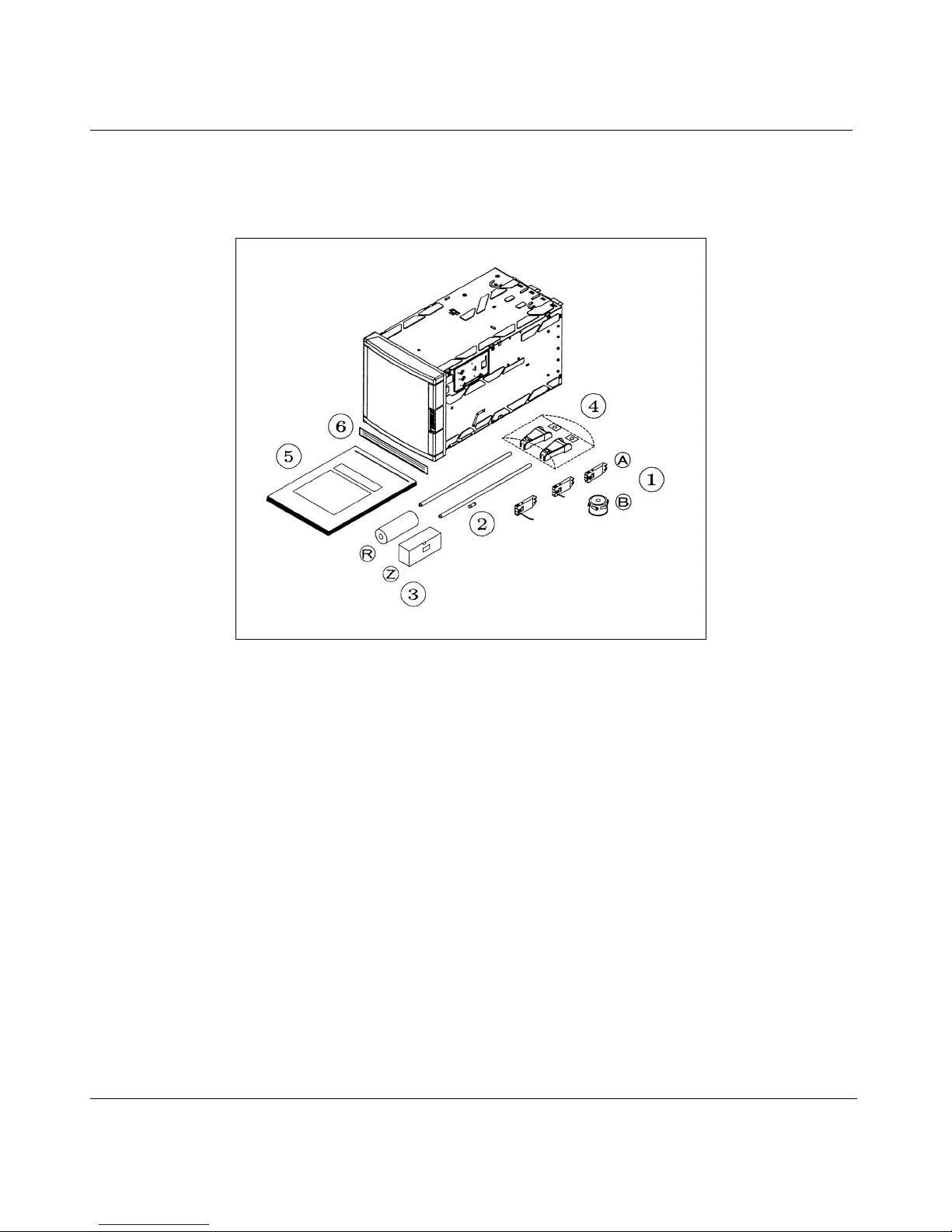
2.2 UNPACKING
Remove the accessories and check them against the figure below.
2. INSTALLATION
1. Ink cartridge(s) (A) or ink wheel (B)
2. Fuse (Spare)
3. Roll (R) or fanfold (Z) chart
4. Mounting brackets with nuts
5. Operator manual
6. Front label
NOTE: In case of missing item, please contact your nearest sales office.
2-2
Page 13
2. INSTALLATION
2.3 PANEL MOUNTING THE RECORDER
2.3.1 Recommendations
This recorder is designed to operate under specific conditions. If you need more information, refer to the
product specification sheet.
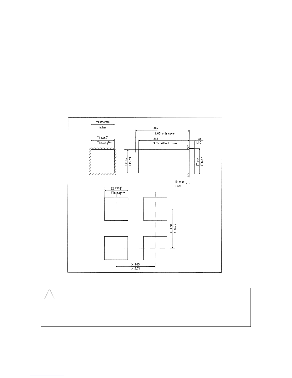
2.3.2 External dimensions and cut-out
Prepare panel cut-out as detailed below:
: Maximum panel thickness 15 mm
Note
!
CAUTION
The maximum temperature inside the cabinet should not exceed the ambient conditions
specific to the recorders. The recorder must be mounted into a panel to limit operator
access to the rear terminals.
Failure to comply with these instructions may result in product damage
2-3
Page 14
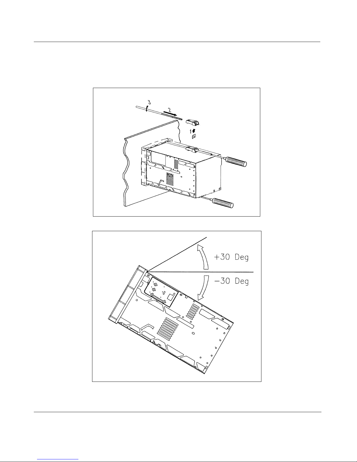
2.3.3 Installing the recorder
To install the recorder, follow the figures below:
Mounting brackets
2. INSTALLATION
Mounting angle limits
2-4
Page 15
2. INSTALLATION
2.4 WIRING THE RECORDER
2.4.1 Recommendations
# All wiring must be in accordance with local norms and carried out by authorized experienced
personnel.
# The ground terminal must be connected before any other wiring (and disconnected last).
# A switch in the main supply is required near the equipment.
# If an external fuse is used to protect the line supply to the recorder, the fuse should match the
recorder fuse rating (fuse type) as well as for the fuseholder.
# Sensor wiring should be run as far as possible from power wiring.
# To reduce stray pick-up, we recommend the use of twisted pair sensor wiring.
# EMI effects can be further reduced by the use of shielded cable sensor wiring. The shield must be
connected to the ground terminal.
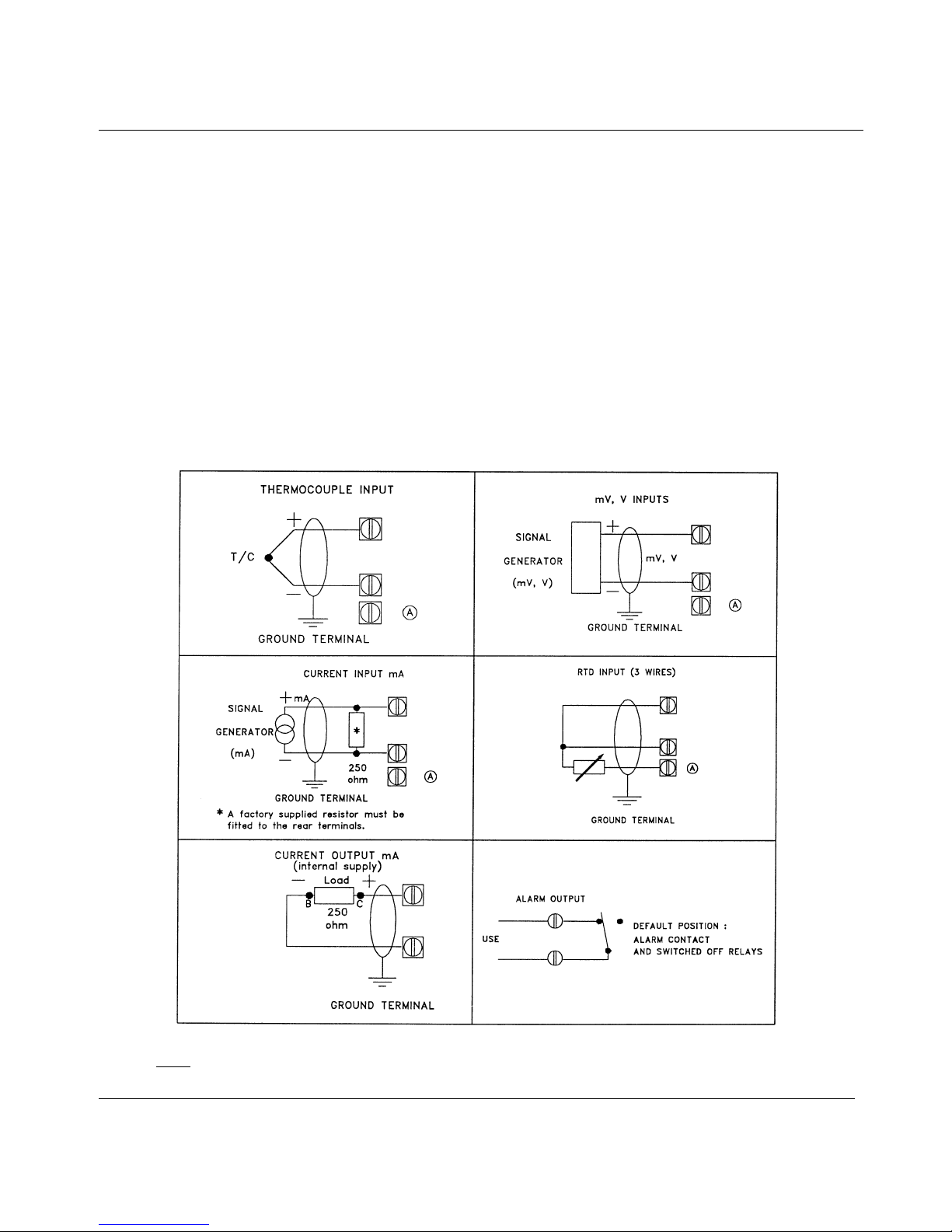
: Terminal (A) is only used for RTD. (See diagrams above.)
Note
2-5
Page 16
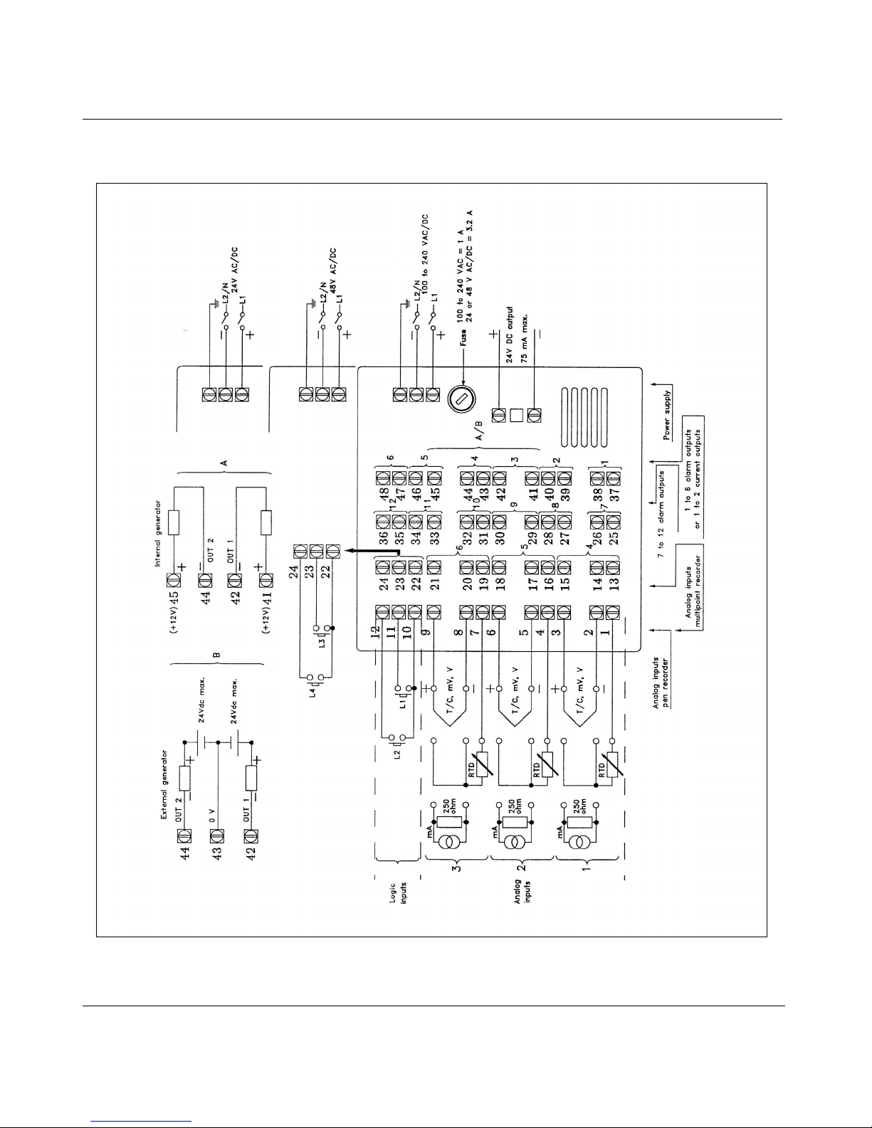
2.5 TERMINAL CONNECTIONS
2. INSTALLATION
2-6
Page 17

2. INSTALLATION
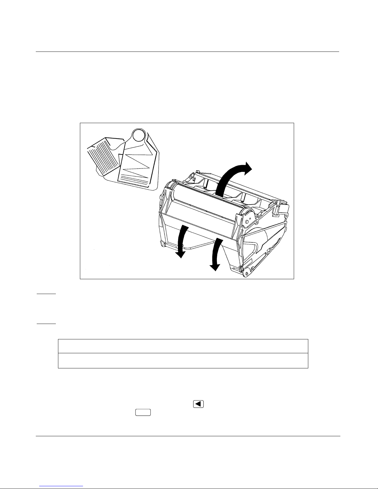
2.6 FITTING THE CHART
2.6.1 Roll chart
Open the chart cassette as shown below and install the chart using the figure on the cassette.
Note 1
Note 2
: To maintain print quality, the print carriage guide rods should be cleaned at six-monthly intervals
with a dry cotton cloth. Lubrificant should NOT be used.
If required, the chart cassette can be cleaned with a damp cotton cloth.
: After the installation of a new chart, close the display and reinsert the chart cassette.
NOTICE
Reset the paper length if configured after installing the new chart.
See paragraph 3.2.1 "Operators keys".
"END PAPER" message: When you see " END PAPER " message on the display ("end of paper" message),
the recorder informs you that the chart arrives at the end.
To remove this message, press
and press
After that, the " END PAPER " message disappears.
ENTER
.
until you read "PAPLG=…" (paper length)
2-7
Page 18
2. INSTALLATION
2.6.2 Fanfold chart
# Open the chart cassette as shown below and install the chart using the figure on the cassette.
# Place the fanfold chart in the upper compartment with the folds in the vertical plane and the slots on
the right hand side.
# Pull out 4 folds of paper and then close the rear metal cover.
Note 1
Note 2
: To maintain print quality, the print carriage guide rods should be cleaned at six-
monthly intervals with a dry cotton cloth. Lubricant should NOT be used.
If required, the chart cassette can be cleaned with a damp cotton cloth.
: After the installation of a new chart, close the display and reinsert the chart cassette.
NOTICE
Reset the paper length if configured after installing the new chart.
See paragraph 3.2.1 "Operators keys".
"END PAPER" message: When you see " END PAPER " message on the display ("end of paper" message),
the recorder informs you that the chart arrives at the end.
To remove this message, press
and press
After that, the " END PAPER " message disappears.
ENTER
.
2-8
until you read "PAPLG=…" (paper length)
Page 19
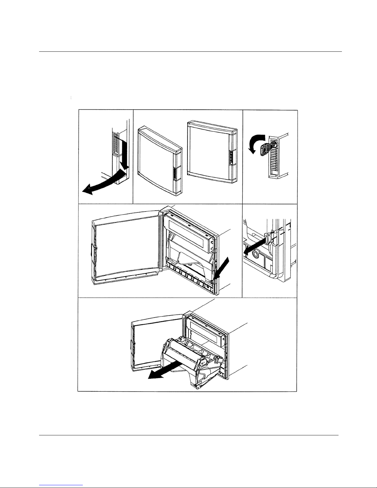
2.7 INSTALLING THE PRINTING SYSTEM
Remove the chart cassette from the chassis as shown below:
2. INSTALLATION
2-9
Page 20
If you have a pen recorder, proceed as shown below:
Open the front display after having removed the chart cassette.
2. INSTALLATION
Insert the pen cartridges.
2-10
Page 21
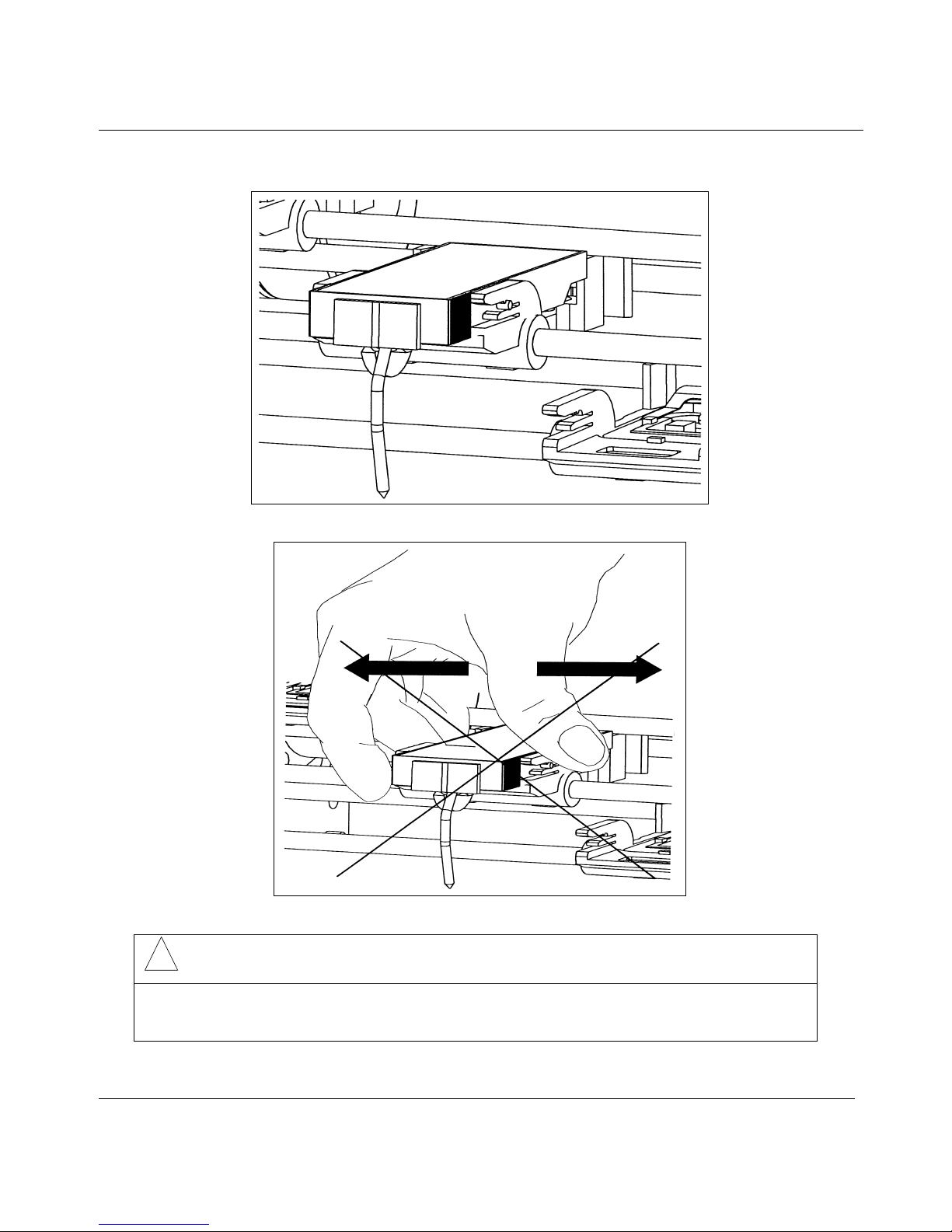
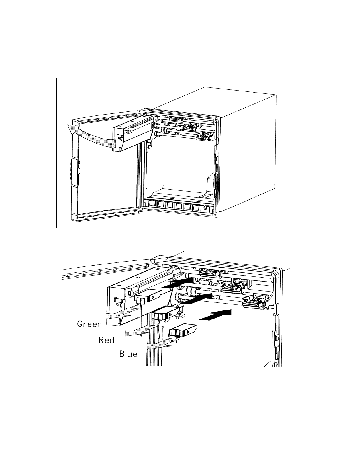
Inserted pen cartridges
2. INSTALLATION
!
CAUTION
Do not move the print head mechanism when the recorder is working.
Failure to comply with these instructions may result in product damage
2-11
Page 22
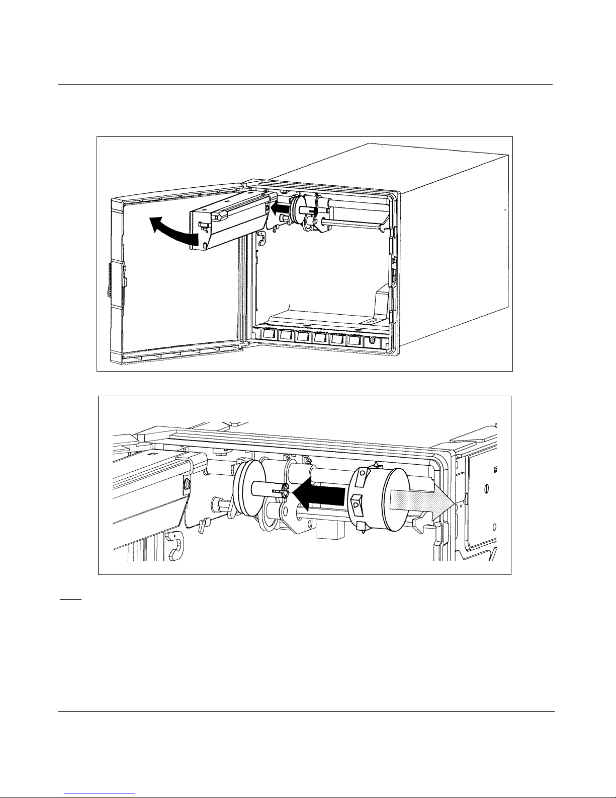
If you have a multipoint recorder, proceed as shown below:
Open the display after having removed the chart cassette.
2. INSTALLATION
Insert the ink wheel.
: The ink wheel should be inserted and rotated counter-clockwise until ratchet engages.
Note
2-12
Page 23
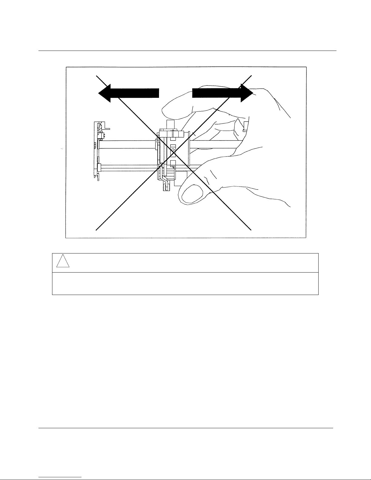
2. INSTALLATION
!
CAUTION
Do not move the print head mechanism when the recorder is working.
Failure to comply with these instructions may result in product damage
NOTE: After each change of chart, it is recommended to make a calibration again.
(See 0% and 100% CHART.)
2-13
Page 24

2. INSTALLATION
FUNCTION TYPE OF SERVICE
PRINTER 0% CHART
DEFINITION: Chart certification to show the current 0% chart position with 0%
print carriage. This is a mechanical adjustment.
HOW TO USE/EXECUTE IT: The message "(channel nb) CAL 0%" with a flashing number. This
number corresponds to the present adjustment (= step motor).
To move to the right, increase this number or to the left, decrease the
number. (You may introduce a negative number.)
You can change the distance value by pressing the keys.
You accept the value by pressing .
You can leave the 0% chart service by pressing .
NOTE: When you press , the head moves and prints at the new 0%
ENTER
ENTER
SETUP
chart calibration.
FUNCTION TYPE OF SERVICE
PRINTER 100% CHART
DEFINITION: Chart certification to show the current 100% chart position with
100% print carriage. This is a mechanical adjustment.
HOW TO USE/EXECUTE IT: The message "(channel nb) CAL 100%" with a flashing number. This
number corresponds to the present adjustment (= step motor).
To move to the right, increase this number or to the left, decrease the
number. (You may introduce a negative number.)
You can change the distance value by pressing the keys.
NOTE: When you press , the head moves and prints at the new 100%
You accept the value by pressing .
You can leave the 100% chart service by pressing .
ENTER
ENTER
SETUP
chart calibration.
2-14
Page 25

2.8 CHECK LIST
1 Have you connected the ground terminal ?
2 Have you connected the sensor(s) correctly ? (Wire type, polarity, etc.)
3 Have you tightened all terminal screws ?
4 Have you installed the ink cartridge(s) or wheel ?
(See figures on pages 2-10 to 2-15.)
5 Have you installed the chart correctly ?
(See figures on pages 2-8 and 2-9.)
2. INSTALLATION
6 Have you closed the display ?
7 Have you fitted the chart cassette in the recorder ?
2-15
Page 26

2-16
Page 27
3. OPERATION
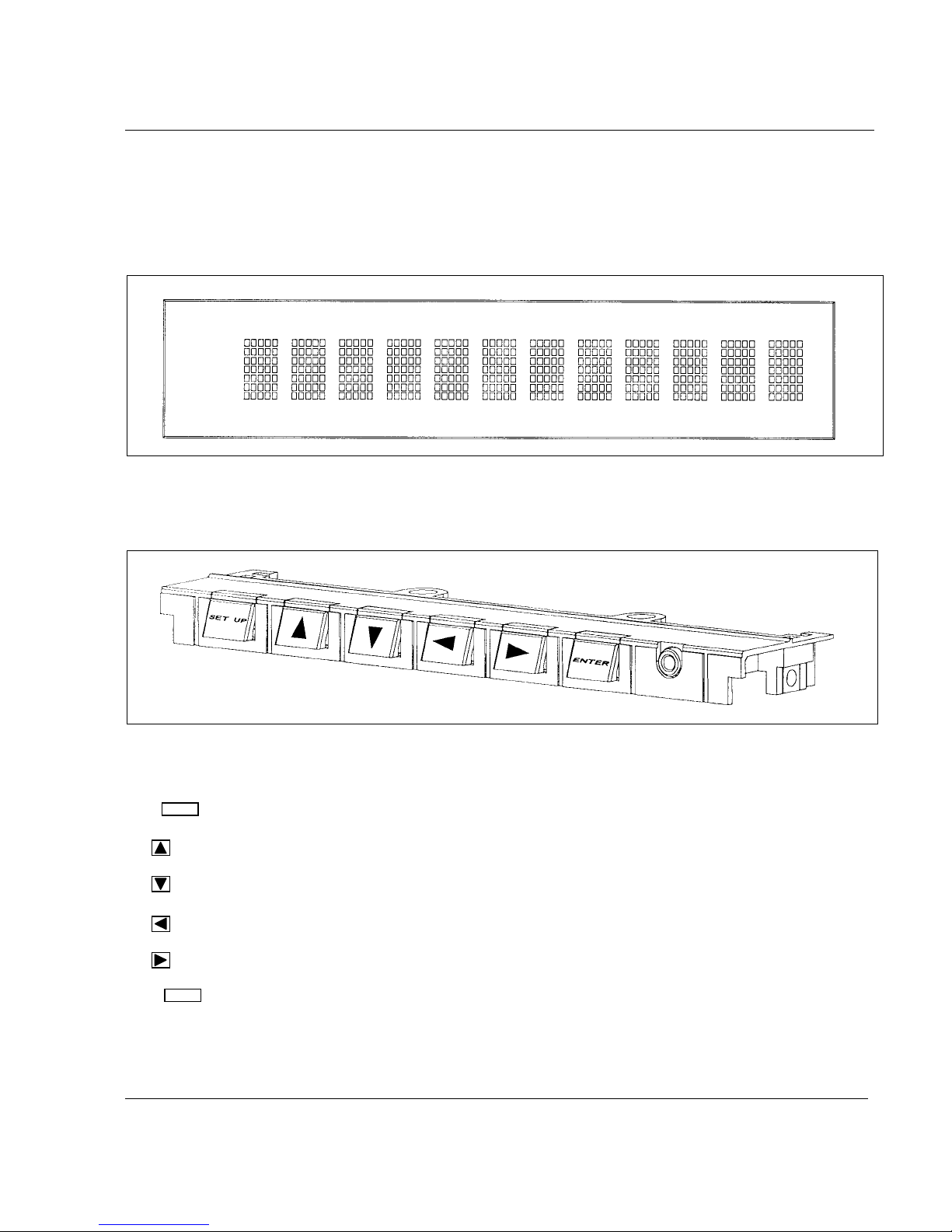
3.1 OPERATOR INTERFACE EXPLANATION
The operator interface comprises the display and keypad.
DISPLAY
The display gives a clear indication of action prompts by means of one li ne of 12 characters.
KEYPAD
The keypad consists of 6 keys:
SETUP
The key allows you to escape from any action menu and return to normal operating m ode.
•
allows ou to HOLD or SCAN the channel display.
•
allows you to select the DIS P LAY TYPE desired.
•
allows you to select the PR I NT action desired.
•
allows you to select the MATH or BATCH action desired.
ENTER
The key allows you to confirm your selected action.
3-1
Page 28
3. OPERATION
3.2 BASIC ACTIONS
Basic actions are executed by using keys wi thout entering the configurati on m ode.
No configuration parameter can be modified.
NOTE:
The keys are enabled and the key is disabled by the default
factory configuration. S ee MMl sub-matrix in the "CONFIGURATION" chapter
to modify the actions abov e.
3.2.1 Operators keys
The 4 keys can be used as operators keys.
These keys can be enabled or disabled in configuration (MMI ).
The selections are:
HOLD DISPLAY SELECT
DISPLAY TYPE
- on CH1
- on CH2
- on CH3
- on CH4
- on CH5
- on CH6
- Display scan
- Analog Input
- Math Res
- Traces
- Traces and Tag
- 1 Bargraph
- 2 Bargraphs
- Date and Time
- Speed in use
- Alarm
- Comm inputs***
* As long as you keep
ENTER
pressed, the chart advances.
** Only if the Math package is enabled.
*** Optional
ENTER
Press to confirm the choice.
- Print Time
- Print PV Values
- Chart Hold
- Chg Speed
- Chart Advance*
- Reset Chart Length
- Print Math Results **
PRINTER MATH/BATCH
- Reset Math 1
- Reset Math 2
- Reset Math 3
- Reset Math 4
- Reset Math 5
- Reset Math 6
- Reset All Math
- Reset Batch #
- Incr. Batch #
3-2
Page 29

3. OPERATION
3.2.2 How to select the display type
Ten display types are available:
• ANALOG INPUTS
Analog input numbers, measured values and temperature actuation units will be displayed.
1 I N 3 2 7 1 . ° C
IN = mnemonic for analog input
Note: For linear actuations, if the low est or the highest values are changed, the unit i s no m ore
displayed.
• COMMUNICATION CHANNELS
Communication channel numbers, values will be displayed.
C 1 1 2 9 5 2 0 . 5
COM = mnemonic for communication channel
• MATHS RESULTS
Maths channel numbers, maths results will be displayed.
M 1 6 1 7 5 5 0 . 8
M = mnemonic for maths results
• CHART TRACES
Channel numbers, measured values and engineering units (configured in the CHART matrix) will be
displayed.
1 3 2 7 . 2 U N I T S
If the channel is in alarm then t he uni ts
UNI T S
will be replaced by the alarm number
AL 1 2
3-3
Page 30

3. OPERATION
• TAG NAMES AND TRACES
Channel numbers and tag names will be displayed.
1 T A G N A M E
then alternately channel number value and unit will be displayed.
1 3 2 7 . 2 U N I T S
If the trace is in alarm condition then the units
UNI T S
will be replaced by the alarm number
AL 1 2
• ONE BARGRAPH
A channel is represented by a 20 segment bargraph.
Channel number and bargraph will be displayed.
!!!!!!!!!
!
1
An "A" will be displayed at the end of the bargraph if the channel is in alarm.
When there is no alarm, the last di gi t shows the trend of the channel.
!!
>
> if the values are increasing, < if the values are decreasi ng.
• TWO BARGRAPHS
(Only for 2 or 3 pen recorder)
Two channels are represented by a 2x20 segment bargraphs.
I
!!!!!!!!!!!!!!!!!!!!
II
!!!!!!!!!!!!!!!!!!!!!!!!!!!!!!!!!!!!!!!!
The first digit represents t he channel num bers di splayed by the bargraphs.
("I" means trace #1, "II" means trace #2, "III" means trace #3)
An "A" will be displayed at the end of the line if one of the channels is in alarm.
3-4
Page 31

3. OPERATION
• DATE & TIME
Day/month, hour: min will be displayed.
3 0 / N O V 1 2 : 0 1
• CHART SPEED
In the trend mode number, speed number, value and unit will be displayed.
S P 1 1 2 0 0 m m / h
• SP1 or SP2 = mnemonic for speed
If the recorder prints in tabular format, then tabular number, tabular interval and unit will be displayed.
T A B 1 1 2 0 m i n
TAB = mnemonic for tabular interval
min = mnemonic for minute
• ALARMS
For each operated alarm, alarm number, alarm state, relay number and relay state will be displayed.
A L 1 1 R L 1 1
ON OFF
ACTIVE INACTIVE
AL = mnemonic for alarm
RL = mnemonic for relay
DI = mnemonic for digital input
EV = mnemonic for event
Then alternately the time of a larm a ctivation will be d isp layed . (Analo g a nd d igita l alar ms dis play)
A L 1 1 1 2 : 1 5
3-5
Page 32

3. OPERATION
3-6
Page 33

4. MODEL SELECTION GUIDE
_ _ _ _ _
_ _
_ _
_
_
_
_ _ _ _ _
_ _ _
_ _
X
)
4.1 PRODUCT IDENTIFICATION
Instructions
Select the desired Key Number. The arrow to the right marks the selections available.
Make one selection each from Tables I through VII.
A complete Model Number must have the designated number of digits in each table.
Ke y Num ber s I II III IV V VI VII
-
-
-
-
VIII
-
KE Y NUMB E R (N ote 1 ) Sele c tion Availa b ilit y
Description
1 Pen Recorder DP101
2 Pen Recorder DP102
3 Pen Recorder DP103
3 Channel Recorder DM103
6 Channel Recorder DM106
TABLE I - MATH FUNCTION (Note 2)
Standard - Channel Difference, Square Root 0
Math Package 1: Add, Multiply, Divide 1
Math Package 2: Pack. 1 + Fo., Group Average, Totalizer, 2
Gas/Liquid Mass Flow
Math Package 3: Pack. 2 + Integ., Group Max, Min, 3
Max-Min, Steam Flow Totalization,
Energy Consumption
Math Package 4:
Pack. 3 + RH, 10
IX
, Envelope, Timers,
4
Carbon Potential
TA BLE II - V OL T AG E (Note 3
85 to 264 Vac/dc 50 Hz Chart speed mm/hr A
85 to 250 Vac/dc 60 Hz Chart speed inch/hr B
24 Volt ac/dc 50 Hz Chart speed mm/hr E
24 Volt ac/dc 60 Hz Chart speed inch/hr
48 Volt ac/dc 50 Hz Chart speed mm/hr G
48 Volt ac/dc 60 Hz Chart speed inch/hr H
ddddd
F
4-1
Page 34

00000
(
)
y
n
4. MODEL SELECTION GUIDE
DDDDD
PPPMM
11111
TA BLE III- OU TP UT S
Selectio
None 0_
Universal Comm unication Option 1 _
RS422/485 Modbus R TU , RS422/485 ASC II,
RS232/V24 ASC II
Modem
2 4 - 2 0 mA A u x ilia r y Ou t p u ts 2 _
2 4 - 2 0 mA A u x ilia r y Ou t p u ts plu s Un iv e r s a l 3 _
Co mmun ic a tion s Option
Alarm Relays: None _ 0
6 Alarm Output _ A
12 Alarm Output _ B
2 Alarm Output _ C
TABLE IV - LOGIC INPUTS
None 0
2 Rem ote Contacts A
4 Rem ote Contact B
TABLE V - CHART CASSETTE
Fan Fold Z
Roll R
12336
eeeee
fffff
ggggg
TABLE VI - DOOR AND CASE
Dark Gra
Door, Plastic Window with Latch 1
Dark Gray Door, Plastic Window, Key Lock 2
Portable Case
Protective Case
(Note 4)
(Note 7)
4-2
5
6
Page 35

4. MODEL SELECTION GUIDE
00000
g
TABLE VII - OPTIONS
None 0 _ _ _ _
Power Supply for Transmitter 24 Vdc (50 mA m ax) B _ _ _ _
None _ 0 _ _ _
Rear Terminal Cover
None _ _ 0 _ _
UL/CSA Approved _ _ C _ _
None _ _ _ 0 _
Additional 3 Inputs for Math Use _ _ _ A _
None _ _ _ _ 0
Certificate of Conformance (F2474) _ _ _ _ B
Certificate of Calibration (F3399)
Certificate of Conformance & User Actuation
Certificate of Cal + Config & User Actuation
User Actuation Configuration
Configuration to customer requirement
(Note 5)
(Note 8)
(Note 6)
(Note 6 & 8)
(Note 6)
(Note 8)
_ G _ _ _
ccccc
_ _ _ _ C
_ _ _ _ D
_ _ _ _ E
_ _ _ _ K
_ _ _ _ L
TABLE VIII - SPECIALS
Selection
None 0 0 0
ST Num ber (Consult Honeywell representative or IM&C M arketing) X X X
TABL E IX - M a n ua ls
lish Operator Manual and Prompts E _
En
French Operator Manual and Prompts F _
German O perator Manual and Prompts G _
Italian Operator Manual and Prompts I _
Spanish Operator Manual and Prompts S _
Swedish Operator Manual and Prompts W _
English, U.S. Format, Product Manual and Prompts U _
None _ 0
English Product Manual _ 1
French Product Manual _ 3
German P roduct Manual _ 4
DDDDD
PPPMM
11111
12336
4-3
Page 36

4. MODEL SELECTION GUIDE
pply
r
Note 1: The units are built with universal input and are delivered with 250 ohm resistors to convert input current
signal 4 to 20 mA into 1 to 5 Volt dc (or 0 to 5 Vdc). These are packed in the product accessories.
Note 2: Models DP1XX P en units supplied with 3 analog inputs when Math Option is ordered. Additional 3
inputs can be selected by specifying Table VII, Optio n XXXAX.
Note 3: The chart speed and frequency can be modified on the unit from key pad.
Note 4: Portable case supplied with dark gray door, plastic window, latch, rear main switch and IEC main plug
connector.
Note 5: Rear cover is used to cover field wiring, this is in addition to the cover on the power supply terminals
which is standard.
Note 6: User defined actuation worksheets need to be completed and supplied with the order.
Note 7: Supplied with metal sleeve, used on portable case option, no rear main switch or IEC main power
plug connector supplied.
Note 8: Customer must su
of the order for the factory to supply the Custom Calibration Test Report (F3399).
RESTRICTIONS
Restriction Lette
Table Selection Table Selection
cVI5, 6
Input Actuation Type and Range for each input in the Free Form section
Av a ila b le On ly With
Not Available With
d VII _ _ C _ _
e III _ A, _ B, _ C
f III 1 _, 2 _, 3 _
o
C Maximum tem perature limit
g
50
4-4
Page 37

4. MODEL SELECTION GUIDE
USER D EFINED AC TU ATION D PR100C /D
Fax to your Honeyw ell Customer Service
CUSTOMER ORDER No.
SALES ORDER No.
TYPE OF ACTUATION - T/C LINEAR (mV) Ma V RTD (Check one)
If thermocouple - complete table for Recorder Operating Temperature for Cold Junction Compensation
Actuation Cold Junc. Eng. Unit Electrical Actuation Cold Junc. Eng. Unit Electrical
1 Value Deg. C Value (mV) 2 Value Deg. C Value (mV)
Lowest Lowest
Average A verage
Highest Highest
USER DEFINED ACTUATION TABLE 1
Enter values for custom actuation (max 50 SEGM E N TS )
Segm ent ENG E lectrical Segment ENG Electrical Segm ent ENG Electrical
Number VALUE VALUE Number VALUE VALUE Number VALUE VALUE
11835
21936
32037
42138
52239
62340
72441
82542
92643
10 27 44
11 28 45
12 29 46
13 30 47
14 31 48
15 32 49
16 33 50
17 34 51
4-5
Page 38

4. MODEL SELECTION GUIDE
USER DEFINED ACTUATION TABLE 2
Enter values for custom actuation (max 50 SEGMEN TS )
Segmen t ENG E lectrical Segment ENG Electrical Segment ENG Electrical
Number VALUE VALUE Number VALUE VALUE Number VALUE VALUE
11835
21936
32037
42138
52239
62340
72441
82542
92643
10 27 44
11 28 45
12 29 46
13 30 47
14 31 48
15 32 49
16 33 50
17 34 51
4-6
Page 39

5. PRODUCT SPECIFICATION SHEET
Technical data
Technology Microprocessor based, with non-volatile memory. Flash memory for
software upgrade via the front jack.
Analog inputs
Pen recorder 1, 2 or 3 continuous traces
Multipoint recorder 3 or 6 channels inputs are scanned by solid state switches and are
galvanically isolated, except for RTD sensors.
Signal source Thermocouple with individual cold junction compensation.
Line resistance up to 1000 ohms T/C, mV, mA, V
RTD Pt 100 3-wire connections, lead resistance per wire 40 Ω balanced.
Basic mathematic functions
Filter A digital filter is configurable per input, 0 to 99 seconds.
Field calibration A channel field calibration - 0% and 100% span - may be made to certify
Burnout T/C, mV, Volt, configurable to upscale, to downscale or none.
Scanning time
(solid state relays)
Input impedance
Stray rejection
Display 12 digit fluorescent display: 8.5 mm high (function display)
Brightness The display brightness is configurable.
Recording span
Scaling Per input, up to 2 analog scales can be configured to be printed on the
Zoning Each input can be configured on 0 to 100%, or 0 to 50%,
Pen offset (Pen recorder) Distance between pen: 2 mm - Offset compensation configurable.
Pen carriage speed 1 second full scale
Square Root extraction (√) ; Differential = (∆T)
input sensor loop.
RTD: inherent upscale. mA: inherent downscale
Pen:
1 pen = 160 ms
2 pens = 240 ms
3 pens = 330 ms
Multipoint:
3 channels = 330 ms
6 channels = 640 ms
10 Mohm for T/C, mV inputs, > 1 Mohm for volt inputs.
Series mode ≥ 60 dB. Common mode at 250 Vac ≥ 130 dB.
configurable in:
- digital PV values with engineering unit in accordance with the input range
- 1 or 2 bargraphs
Can display analog input, tags, maths results, communication, alarms or
event messages.
chart with the engineering unit, channel reference and tag name.
Each input can be configured differently.
or 50 to 100% of the chart.
Chart definition: 1 step = 0.2 mm
5-1
Page 40

5. PRODUCT SPECIFICATION SHEET
Technical data
Chart length
Pen trace
Pen
Multipoint
Chart speed 1 or 2 chart speeds, fully configurable, selected by a logic input, alarm or
Speed setting Pen: 1 to 6000 mm/h (0.04 to 240 inch/h).
Stepping chart motor Resolution 0.12 mm
Product configuration
Front configuration - 2 product configurations can be stored and selected by the front keys.
PC configuration Through the front jack the unit can be configured from a PC through a PC
Logic inputs
Actions Up to 4 dry contact inputs (1.5 mA, 12 Vdc)
Alarms
Setpoint 12 alarm setpoints, freely assignable to any channel and output relay.
Function Can trigger a message, print channel red in alarm, print in alarm, change
Output 2, 6 or 12 SPST relay outputs: 2 A, 250 Vac on resistive load.
Fanfold 18 m (as DIN 16230)
Roll 24 m
1400 m per pen
250 m per color
configuration.
Speed 1: fully adjustable per step of 1 mm/h, within limit
Speed 2: fully adjustable per step of 1 mm/h, within limit
Mpt: 1 to 1500 mm/h (0.04 to 60 inch/h)
Continuous traces in color, dotted traces in configurable color with regular
chart documentation (configurable).
- A very simple and interactive product configuration can be carried out on
the product with 6 front keys. A friendly program with prompt messages
confirms the operation. The prompt messages can be selected in the
different languages: English, German, French, Spanish, Italian or Swedish.
A 2-level password protects the unit from non-authorized modification
(level 1 = limited access ; level 2 = full protection)
interface. This provides the facility to copy the configuration, modify,
store, upload or download the product configuration or make a service
diagnostic, or upgrade a new software or linearize 2 special customer
sensors. (50 segments each).
Change chart speed 1 to speed 2, tab interval 1 to tab interval 2, digital
print-out, print message, print inhibit, event trace, print a batch message,
tabulate maths calculations. Event marking: Pen: Pen 1 used as operation
marker on the right side of the chart for event 1 and on the left side of
the chart for event 2.
Mpt: 4 traces maximum on the chart. The trace position and the color are
configurable.
Full configurability of setpoint, hysteresis and alarm type (high, low rate
of change, deviation).
the range, change the speed, print digital PV values, trigger the event
precursor.
Contact N.C. in alarm condition (configurable in N.O.)
5-2
Page 41

5. PRODUCT SPECIFCATION SHEET
Technical data
Alphanumeric documentation
Messages 12 freely assignable and configurable messages of 14 characters each,
Batch header One batch message of 4 lines of 14 characters, fully configurable, with
Process variable The traces can be assigned to analog input, mathematics calculations or
Tag name Each channel can be named by 8 characters
Event precursor
Stand-by
Downloading
Mathematics package
(optional)
Digital communication (optional)
Protocols
PC supervision Through ASCII communication, application software gives the facility to
Autodial The RS232 ASCII communication can dial automatically a phone number
Event The recorder can be configured to deliver an output signal (alarm relay)
including the specific German and Swedish letters.
Can be printed with the date/time on top of the traces by alarms, logic
inputs or communication.
incremented batch numbers and date/time. Printed through digital input
and saved upon power interruption.
communication inputs, and are printed in channel color. Periodic digital
printing at time intervals configurable from 1 to 1440 minutes. Digital
print-out of PV values through alarms, digital inputs, communication or
front keyboard.
The acquisition data is stored in a buffer memory. (FiFo)
A stand-by message is periodically printed.
On event (alarm, digital input, front key, communication) the data is
downloaded to be printed on the chart at pre-configured speed.
The history before and after the event represents about 50 mm of chart
paper.
Many functions are available such as: - Energy consumption
- Basic mathematics functions - Vacuum pressure
- Square root - Averages
- Fo sterilization - Min., max.
- Totalization - Timers
- Mass flows - Carbon potential
The maths calculations and results are stored during power interrutpions
RS232 ASCII communication to PC application. RS422 or RS485 ASCII
communication output. RS422 or RS485 Modbus RTU communication
output.
read PV's, alarms or event status, to store the information on a file, to
send a message to the recorder or to modify the product configuration.
of a remote station to send via modem an alarm message or a periodic
report.
Use of this feature can cause communications conflicts if data
acquisition software attempts to communicate with the recorder at the
same time. During an Autodial the recorder becomes the master on the
communications link.
on a recorder event such as burnout, paper cassette out, battery fail,
alarm condition, communication interrupted.
5-3
Page 42

5. PRODUCT SPECIFICATION SHEET
Technical data
Current output (optional) 2 current output, signals 4 to 20 mA reference conditions. Configurable
on analog inputs, mathematic calculations, communication signals.
Accuracy 0.1% reference conditions.
(Add measure accuracy for analog outputs.)
Temperature drift of 0.1% per 10°C in the rated limits. (0 to 50°C ;
85 to 264 V). Voltage supplied by the recorder: +12 V with a max.
resistance load of 400 ohms.
Or
External supply voltage: ≤24 V with a max. resistance load such as
(Vext - 12) / 0.02 ≤R ≤(Vext - 4) / 0.02
Power supply 85 to 264 Vac 50 Hz or 24 or 48 Vac/dc (+10-15% nominal)
To transmitters 24 V, 75 mA max. (optional) (75 mA available from 100 V)
Power consumption 3 pens or Mpt: 55 VA max. (active power 30 W)
Supply voltage 100 - 240 Vac
Frequency range 50/60 Hz
Power max. 55 VA
Clock timer
Format Year, month, hour, minute can be set.
Power interruption Battery backed (10 years time, 3 years off power)
-
Accuracy ±10
Packaging
Weight Pen or Mpt: 3.5 kg
Front face
Depth 245 mm/9.7 inch behind panel, including terminals and line protection cover
Front window Polycarbonate
Front protection IP 54 (IEC 529)
Lock Latch or key (DIN 43832-N)
Construction Silicon-free
Chart illumination Fluorescent light
Option Rear terminal cover, portable case.
Mounting
Wiring
5
144 × 144 mm according to DIN 43718
Panel mounting ±30° from horizontal
Rear screw terminals. Terminal modules are plugged on the instrument.
5-4
Page 43

5. PRODUCT SPECIFICATION SHEET
Technical data
Writing
Pen 1 cartridge per pen, fiber tip, 1400 m of trace per color (blue, red,
green)
Multipoint 1 print wheel, 6 colors, 250 m of trace per color (purple, red, black,
green, blue, brown).
Noise immunity This product is in conformity with the protection requirements of the
following European council directives:
• 73/23/EEC – Low Voltage directive
• 89/336/EEC – EMC Directive
Conformity of this product with any other “CE Mark” Directive(s) shall
not be assumed.
EMC Classification:
• EN 50081-2-1993 Electromagnetic Compatibility – General
Emission Standard, Part 2: Industrial Environment.
• EN 50082-2-1995 Electromagnetic Compatibility – General
Immunity Standard, Part 2: Industrial Environment
Safety protection Complies with IEC 61010-1 and UL 3121-1 for process control
instrumentation Pollution Degree 2, Installation category II.
Electrical insulation
Input to input Test voltage 280 Vac or Vdc for 1 minute (except for RTD input)
Input to ground Test voltage 2.1 kVdc for 1 minute
Input to line voltage Test voltage 2.1 kVdc for 1 minute
Line voltage to ground Test voltage 2.1 kVdc for 1 minute
Alarm relay to ground Test voltage 2.1 kVdc for 1 minute
Logic input to ground Test voltage 500 Vdc for 1 minute
Temperature
Ambient 0 to 50°C (32 to 122°F) for Fan Fold
Storage
Humidity
Roll
Fanfold 15 to 80% RH non-condensing
Vibrations Frequency:
0 to 60° C (32 to 140°F) for Roll Chart
-40 to 70°C (-40 to 158°F)
10 to 90% RH non-condensing
10 to 60 Hz, amplitude 0.07 mm
60 to 150 Hz, acceleration 1 g
5-5
Page 44

5. PRODUCT SPECIFICATION SHEET
Technical data
Reference conditions
Temperature
Humidity
Line voltage nominal
Source resistance
Series mode 0 V
Common mode 0 V
Frequency nominal
Accuracy Accuracy of displayed values: 0.1 % of the selected input range * (IEC 873)
Rated limits and associated
drifts
Parameter Rated limits Influence on accuracy
Temperature 0 to 50°C
Supply voltage 85 to 264 Vac No influence
Source resistance T/C, mV
RTD
Humidity 10 to 90% RH at 25°C 0.1% max.
Long-term stability 0.1% per year
Vibrations 1.25 mm at 0 to 14 Hz
Extreme conditions
Operating
Temperature 0 to 60° C (32 to 140°F)
Humidity 10 to 90% RH non-condensing
Storage
Temperature -40 to 70°C (-40 to 158°F)
Humidity 5 to 95% RH non-condensing
* Refer to "Available ranges" tables for exceptions.
23°C ± 2°C (73°F ± 3°F)
65% RH ± 5% RH
± 1 %
0 Ω
± 1 %
For a 4/20 mA input, you must add the resistor accuracy.
Cold junction accuracy: 0.5°C
Chart resolution: 0.2 m
0.1% per 10°C of change
(32 to 122° F)
1 g at 14 to 250 Hz
Cold junction 0.3°C/10°C
6 µV per 100 Ω of line
0.1°C per Ω in each wire
resistance
1000 Ω max.
balanced leads
40 Ω max.
5-6
Page 45

5. PRODUCT SPECIFICATION SHEET
Available ranges
Linear RTD/OHMS Thermocouple
0/10 mV
-10/10 mV
0/20 mV
-20/20 mV
0/50 mV
-50/50 mV
10/50 mV
0/100 mV
-100/100 mV
0/500 mV
-500/500 mV
0/1 V L -200/870°C N -20/1300°C
-1/1 V L -328/1598°F N -4/2372°F W-W 26 -20/2320°C
0/2 V W-W 26 -4/4208°F
-2/2V
0/5 V
-5/5 V
1/5 V
0/10 V
0/20 mA
4/20 mA
∗∗∗∗
∗∗∗∗
OHM 0/2000 K -200/1370°C T -200 /400°C B 40/1820°C
K -328/2498°F T -328/752°F B 104/3308°F
R -20/1760°C
R -4/3200°F
∗∗∗∗
mA inputs for 250 ohms input resistor
(Accuracy: The tolerance for the resistor
must be added to the specifications.)
Notes:
For non-linear temperature transmitter (1 to 5 Vdc, 4 to 20 mA, 0 to 5 Vdc, 0 to 20 mA), the transmitter
range must be identical to the full actuation range of the recorder.
Provision for T/C input for remote compensation box at fixed temperature of 50°C or 60°C. When
temperature is not fixed, any input can be used as remote compensation temperature measurement.
Pt 100 Ω at 0° C
IEC -50/150°C
IEC -58/302°F
IEC 0/100°C
∗∗∗∗ ∗∗∗∗
IEC 32/212°F
IEC 0/200°C
∗∗∗∗ ∗∗∗∗
IEC 32/392°F
IEC 0/400°C
∗∗∗∗ ∗∗∗∗
IEC 32/752°F
IEC -200/500°C
IEC -328/932°F
Ni 50 Ω -80/320°C
Ni 50 Ω -112/608°F
Ni 508 Ω -50/250°C
Ni 508 Ω -58/482°F
Cu 10 Ω -20/250°C
Cu 10 Ω -4/482°F
OHM 0/200 K 32/2192°F T 122/302°F
J -50/150°C S 0/1600°C U -50/150°C
∗∗∗∗ ∗∗∗∗
JIS -50/150°C
∗∗∗∗ ∗∗∗∗
JIS -58/302°F
JIS 0/100°C
∗∗∗∗ ∗∗∗∗
JIS 32/212°F
JIS 0/200°C
∗∗∗∗ ∗∗∗∗
JIS 32/392°F
JIS 0/400°C
∗∗∗∗ ∗∗∗∗
JIS 32/752°F
∗∗∗∗ ∗∗∗∗
JIS -200/500°C
∗∗∗∗ ∗∗∗∗
JIS -328/932°F
∗∗∗∗ ∗∗∗∗
J -58/302°F S 32/2912°F U -58/302°F
∗∗∗∗ ∗∗∗∗
J 0/400°C S -20/1760°C U 0/150°C
∗∗∗∗ ∗∗∗∗
∗∗∗∗ ∗∗∗∗
∗∗∗∗ ∗∗∗∗
∗∗∗∗ ∗∗∗∗
J 32/752°C S -4/3200°F U 32/302°F
∗∗∗∗ ∗∗∗∗
J -200/870°C U 50/150°C
J -328/1598°F N 0/400°C U 122/302°F
∗∗∗∗ ∗∗∗∗
N 32/752°F U -200/400°C
L -50/150°C N 0/800°C U -328/752°F
∗∗∗∗ ∗∗∗∗
L -58/302°F N 32/1452°F
∗∗∗∗ ∗∗∗∗
L 0/400°C N 0/1200°C NiMo 0/1400°C
∗∗∗∗ ∗∗∗∗
L 32/752°F N 32/2192°F NiMo 32/2552°F
W5-W 26 -
20/2320°C
∗∗∗∗ ∗∗∗∗
∗∗∗∗ ∗∗∗∗
∗∗∗∗ ∗∗∗∗
∗∗∗∗ ∗∗∗∗
∗∗∗∗ ∗∗∗∗
K 0/400°C T -50/150°C W5-W 26 -4/4208°F
K 32/752°F T -58/302°F
K 0/800°C T 0/150°C
K 32/1452°F T 32/302°F PR 20-40 0/1800°C
K 0/1200°C T 50/150°C PR 20-40 32/3272°F
∗ ∗
Accuracy: 1°C or 1.8°F
5-7
Page 46

5. PRODUCT SPECIFCATION SHEET
5-8
Page 47

6. CONFIGURATION
6.1 OPERATOR INTERFACE
The operator interface comprises the display and keypad used for recorder configuration.
DISPLAY
The display gives a clear indication of the configuration prompts by m eans of one line of 12 characters.
KEYPAD
The keypad consists of 6 keys:
SETUP
A clear understanding of keypad use is vital for any operation like Reading/Writing (R/W ), Printing
(PRN) or Service (SRV).
!
! ACCESS TO CONFIGURATION
!!
Access to Read/Write Configuration (R/W), P ri nt Configuration (PRN ) or Service (SRV) i s obtained by
pressing the key.
SETUP
ENTER
!
! THE PASSWORDS
!!
To protect the recorder against unauthorized access, the operator has to enter a password. There are
two possible levels of access:
• Password #1 allows limited access to conf i guration.
• Password #2 allows full access to Read/Write Configuration, Print Configuration or Service.
!
! HOW TO ENTER THE PASSWORDS
!!
• Use of keys allows you to modify the value of one digit of the password and the
keys are used to select the different digits of the modifi ed v alue.
• Press to update your modification.
• Or Press to exit configuration mode.
ENTER
SETUP
NOTE: If you lost your password, please contact your nearest service center.
6-1
Page 48

NORMAL RU N
SET UP
PASSWORD
SET UP
ENTER
TO ENTER
A NEW VALUE
6. CONFIGURATION
SET UP
TO RETURN TO M ENU
OR TO NORMAL RUN
TO CHOOSE THE DESIRED
PARAMETER
ENTER
R/W
PRN
SRV
TO ACCESS
FUNCTIONS
ANALOG
MATH
(option)
ALARM AN
DIGITAL
CHART
BATCH
TO ACCESS
PARAMETERS
ENTER
SENSOR RANGE
FUNCTION
COEF A COEF B COEF C VAR IAB A VARIAB B
*
TYPE CH DIFF
POSITION #RED TRAC *TR COLOR *TRACE *PRNT MSG
MESSAGE iMESSAGES
TAG NAME ENG UNIT DECIMAL MIN RG1 MAX RG1 RG1 COL
RG USED TRACE
TIME DATE LANGUAGE IDNTIF
T/C COMP FILTER LOW VAL HIGH VAL
*
CH
#
MESSAG #
RG2 COL
ACTION RELAY #PRNT MSGAL=RED
MESSAG #MSG COL
#
MAX RG2 M IN RG 2
*
FREQUNCY PASSWRD 1MISCEL
#
BACKUP BATCH
VARIAB CSTARTRESETBACKUP
CH DIFFAL TYPECHA NN ELOCCURNCEHYSTERESSP VALUE
PASSWRD 2MATH PAKUSE CONF
ZERO ADJ STD MATH BURN OUT
MSG COL
ACTION RELAY
ZONING
*
*
RESETSTARTLINE 4LINE 3LINE 2LINE 1
#
MODE
PRINTER
EVENT
MMI
CUR OUT
(Option)
FUNCTION
PRT RANG
PRT TIME PRT TAG
TYPE RELAY
#
CH
LOW VAL HIGH VAL
*
SPD USEDSPEED 2
REC MODE
SPEED 1SPD UNITCHART LG
PRT INTVPRT PV
*
PEN OFFS
#
DISPLAY
KEY LEFTK EY UPKEY DOWN KEY RIGH DISPLAY BRIGHT
PARAMETER
PRT MODE
**
TABULAR 1
TABULAR 2
*
*
* Available on Multipoint recorders only.
** Available on Pen recorders only.
FUNCTION ORGANIZATION WITH PASSWORD #2
6-2
Page 49

NORMAL RUN
SET UP
PASSWO RD
ENTER
SET UP
TO ACCESS
FUNCTIONS
ENTER
ENTER
TO ENTER
A NEW VALUE
6. CONFIGURATION
SET UP
TO RETURN TO MENU
OR TO NORMAL RUN
TO CHOOSE THE DESIRED
PARAMETER
R/W
ANALOG
ALARM AN
MESSAGES
CHART
MISCEL
PRINTER
MMI
MMI
TO ACCESS
PARAMETERS
FILTER
SP VALUE HYSTERES
MESSAGE i
TAG NAME MIN RG1 MAX RG1 RG1 COL
TIME DATE IDNTIF
DISPLAY BRIGHT
MODE FUNCTION PARAMETER
*
MIN RG2 MAX RG2
ZONING
RG2 COL
#
SPEED 2SPEED 1SPD UNIT SPD USED TABULAR 1*TABULAR 2
*
*
FUNCTION ORGANIZATION WITH PASSWORD #1
* Available on Multipoint recorders only.
6-3
Page 50

6. CONFIGURATION
!
! READ/WRITE ACCESS TO PARAMETER VALUES
!!
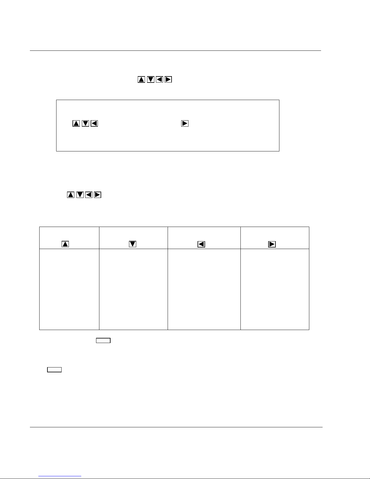
• Parameter selection
Use of keys allows you to select the parameter you want to read/write.
Use of keys allows to select the channel on wich you want to read/write the parameter.
ENTER
Press to confirm your selection, or press to return to main function.
If necessary, the recorder stops measuring and print i ng duri ng configuration access. In this case, the
"CONFIRM." message will be displayed. Press to confirm or press to scape.
• Value of parameter
If you leave a key for a few seconds, the recorder will display alternately the name and the current
value.
• Parameter modification
Press to begin the modificat i on of param eter.
ENTER
The current value blinks.
Some parameters require text select i on w hi l e ot hers requi re num eri cal v al ues.
and keys permit, as applicable, t he sel ection of desired text or increment /decrement of
numerical value.
and keys can be used to shift the position of the digit to be changed.
Press to confirm your change.
ENTER
Or press to come back to parameter selection.
SETUP
SETUP
ENTER
SETUP
6-4
Page 51

6. CONFIGURATION
6.2 ONE EXAMPLE: HOW TO SET THE CHART SPEED
! Press key.
! Enter password #1.
! Press .
! Use of keys allows you to select the R/W configurati on m ode (read/write configurat i on).
! Use of keys allows you to select the PRINTER function.
! Press to confirm your funct i on t ype selection.
! Parameter selection
Use of keys allows you to select SPEED 1.
Press to confirm your selection.
Use of keys allows you to modify the value of one digit. If necessary, the
keys are used to shift the positi on of the digit to be changed.
Press to confirm your modification.
Press to come back to main function.
Press to return in normal operation.
SETUP
ENTER
ENTER
ENTER
ENTER
SETUP
SETUP
6-5
Page 52

6.3 PROMPTS EXPLANATION
6. CONFIGURATION
PARAMETERS:
SENSOR
RANGE DISPLAY ACTUATION RANGE
T/C COMP To select the channel number to measure the temperature of a remote
FILTER ♣
LOW VAL Engineering value corresponding t o l ow l i m i t of the selected input
HIGH VAL Engineering value corresponding to high limi t of the selected input
BURN OUT Allows you to define the safety backup position to activate alarms
STD MATH 2 mathematical functions are included as standard in the recorder.
CH # Second channel used w hen O P T M AT H = CH DIFF
ZERO ADJ Zero adjustment means to offset /bias the calibration of t he i nput .
ANALOG FUNCTION
Basic sensor type used on each channel.
Factory configuration
position.
For directly connected temperature sensors and non- l i near
temperature transmitters, the actuation selection defines the
linearisation routine used to produce a linear chart scal e. F or l i near
transmitters, the selection simply defines the transmitter's electrical
range/span.
The choice of actuation offered by the recorder during configuration
will depend upon the sensor selected.
compensation box. This setti ng eliminates the variable cold j unction
and implements the hot box tem perature.
Application: To use an uncontrolled rem ote compensation box channel
#.
You may wish to apply a fi l ter to noisy signals. However i f you want
to display and record pulses, square waves or other rapidl y changing
inputs without damping, choose 0 f ilter value.
actuation range.
actuation range
(if configured) in case of sensor burnout. The trace can go either on
the right (upscale) or on the left (downscale).
These functions apply only to anal og i nputs.
Otherwise choose 0 Value = Factory Cal i bration.
Adjustments are made directly in Engi neeri ng uni t . (Ex.: 5 = 5° C)
: All CH are configured in T/C, mV , V range
♣ Accessible with the password #1
6-6
Page 53

6. CONFIGURATION
ALARM AN FUNCTION
PARAMETERS:
SP VALUE
HYSTERES ♣
Hysteresis is expressed in Engineering units and is added to low
OCCURNCE
CHANNEL
AL TYPE
CH DIFF
RELAY #
ACTION
MESSAG #
MSG COL
PRNT MSG
AL = RED
♣
The alarm switches from OFF to ON when the SP value is
reached.
Establishes the alarm hysteresis. Al arm s sw i tch ON at set point
but switch OFF value depends on t he hy steresis setting.
alarm and subtracted from high alarm set points to establish the
alarm release value.
Defines the number of alarm occurrences needed after power on
for alarm operation or after start up a new batch.
Channel on which alarm is applied (Anal og 1..6, com 1..6 , math
1..6)
Type of alarm (High, low, differential, ...)
Second channel used if alarm type is di fferential.
Selection of relay activ ated in alarm
Action on printer in case of alarm
(None, print on alarm, change range, ...)
Selection of alarm message to be pri nted
Multipoint only
Color of alarm message
Defines the conditions to pri nt the message on alarm change.
Multipoint only
Specifies if the trace of channel must be printed in red during alarm.
♣ Accessible with the password #1
6-7
Page 54

6. CONFIGURATION
DIGITAL FUNCTION
PARAMETERS:
TYPE
CH DIFF Second digital input to use if t he type is differential
ACTION Acti on on pri nt er in case of digital input change
RELAY # Selection of relay activated
MESSAG # Selection of message to be printed
MSG COL Multipoint onl y
PRNT MSG Defines the condition to print the message on Event Change.
TRACE Enables/disables the trace of t he ev ent.
TR COLOR Multipoint only
RED TRAC Multipoint only
POSITION
Type of digital input
Color of the message
Defines color of trace.
Specifies if digit al i nput trace must be printed in red on event .
Multipoint only
Defines the trace positi on (open contact) on the chart. (In %)
MESSAGES FUNCTION
PARAMETERS:
MESSAGE
♣
To configure the messages. (14 characters)
♣ Accessible with the password #1
6-8
Page 55

6. CONFIGURATION
CHART FUNCTION
PARAMETERS:
TAG NAME
ENG UNIT
DECIMAL
MIN RG1 ♣
MAX RG1 ♣
RG1 COL ♣
MIN RG2 ♣
MAX RG2 ♣
RG2 COL ♣
ZONING ♣
TRACE
♣
Tag of name corresponding chart channel
Chart channel units
Decimal point configurat i on
Lower limit of chart range 1
Upper limit of chart range 1
Multipoint only
Color of range 1
Lower limit of chart range 2
Upper limit of chart range 2
Multipoint only
Color of range 2
Defines chart zone for printing. (0%-50%, 50% - 10 0 % , 0%-
100%)
Defines the variable to print ( A nal og i nput 1 ..6, Comm 1..6,
Math 1..6, None)
RG USED You may select whether the input channel will be printed
normally (range 1 or 2) or on alarm ( w i th range 1 or 2).
♣ Accessible with the password #1
6-9
Page 56

6. CONFIGURATION
MISCEL FUNCTION
PARAMETERS:
TIME
DATE ♣
LANGUAGE
IDNTIF # ♣
FREQUNCY To select the line frequency
PSSWRD 1 Used to provide a li m ited access to configuration
PSSWRD 2 Used to provide f ul l access to configuration
MATH PAK Type of optional mat hs package
USE CONF Selection of the desi red conf iguration number
♣
Real time clock setti ng
Real time clock date
Operator information and configuration language
Identification number of the instrument which will be printed on
the chart.
♣ Accessible with the password #1
BATCH FUNCTION
PARAMETERS:
LINE 1 Configuration of the first line of t he batch message
LINE 2 Configuration of the second line of the batch message
LINE 3 Configuration of the third line of the bat ch m essage
LINE 4 Configuration of the fourth line of the bat ch m essage
START
RESET
BATCH # Batch number used at RESET condition.
BACKUP Store the batch number i n case of power interruption.
BATCH ACTIVATION CONDITION:
The START condition defi nes w hen bat ch pri nting must start.
The recorder pauses each time the start condition occurs and
then prints the batch description and i ncrem ent s the batch
number.
BATCH NUMBER RESET CONDITION:
The RESET condition defines w hen the batch number must
reset.
6-10
Page 57

6. CONFIGURATION
PRINTER FUNCTION
PARAMETERS:
CHART LG
SPD UNIT ♣
SPEED1 ♣
SPEED2 ♣
SPD USED ♣
TABULAR 1 ♣
TABULAR 2 ♣
REC MODE Recording mode allows you to print normally, to st op the printer,
PRT MODE Multipoint only
PRT INTV
Total chart length of the chart rol l or fanfold
Speed unit (mm/h or inch/h)
Value of speed 1 (Using speed unit )
Value of speed 2
Defines the speed in use or the tabular in use.
Multipoint only
Tab 1 prints interval. (I n m i nute)
Multipoint only
Tab 2 prints interval.
to trigger the printer on alarm wit h (or without) return to standby.
Under this heading you must choose whether recording will be
trend mode or tabular mode.
Separation (in millimeters) of PRT PV interval for periodic
printing.
PRINT PV Periodic of P V values, time and digit al i nput status.
PRT RANG Periodic printing of the chart ranges.
PRT TIME P eri odi c pri nt i ng of "TIME, DATE, SPEED , CHANNEL ID"
PRT TAG Multipoint only
Printing of the tag name w i th the channel number
PEN OFFS Pen only
Pen offset
♣ Accessible with the password #1
EVENT FUNCTION
PARAMETERS:
TYPE
RELAY # Selection of relay activated i n ev ent condition
DISPLAY Enabl es/disables a display warning in event occurrence
Type of event
6-11
Page 58

6. CONFIGURATION
MMI FUNCTION
PARAMETERS:
KEY DOWN
KEY UP
KEY LEFT
KEY RIGH
DISPLAY ♣
BRIGHT ♣
To modify the display indi cation in normal operation.
To stop the display scanning in normal operation.
To modify the printer operation.
To reset the maths functions or batch num ber.
Type of i nf orm ation to display in run mode at power on.
To modify the display brightness during operat i on.
♣ Accessible with the password #1
* See paragraph 3.2 "Basic actions" in Operation section.
CUR OUT FUNCTION *
PARAMETERS:
SLOT 4
*
*
*
*
SLOT 4
SW 1
CURRENT GENERATOR
SUPPLIED FROM
THE RECORDER
CH #
LOW VAL Low value for a 4 mA out put
HIGH VAL High value for a 20 mA output
Defines the variable to out put. (Analog input 1.. 6 , comm 1..6,
math 1.6, none)
CURRENT GENERATOR
SUPPLIED FROM
THE RECORDER
* This function appears only if the current output board is present.
6-12
SW 1
Page 59

7.1 PARAMETERS LIST
FUNCTION PARAMETER CLASSIFICATION
NAME OF THE
FUNCTION
DEFINITION :
HOW TO MODIFY IT :
POSSIBLE VALUES :
SEE ALSO :
EXAMPLE :
NOTE :
WARNING :
7. DETAILED CONFIGURATION
IMPORTANCE OF THE
PARAMETER :
NAME OF THE
PARAMETER
EXPLAIN THE ROLE OF THE PARAMETER
2 POSSIBILITIES :
- BY SELECTING A NEW VALUE I.E. USING THE KEYS
- BY ENTERING A NEW VALUE
LIST OF POSSIBLE VALUES OR LIMITS
! RARELY USED
!! NOT OFTEN USED
!!! OFTEN USED
7-1
Page 60

7. DETAILED CONFIGURATION
!ANALOG
!ALARM AN
!DIGITAL
!MESSAGES
!CHART
!MISCEL
!BATCH
!PRINTER
!EVENT
!MMI
!CUR OUT
7-2
Page 61

7. DETAILED CONFIGURATION
FUNCTION !
ANALOG
PARAMETERS ! SENSOR
! RANGE
! T/C COMP
! FILTER
! LOW VAL
! HIGH VAL
! BURN OUT
! STD MATH
! CH #
! ZERO ADJ
7-3
Page 62

FUNCTION
ANALOG
DEFINITION :
HOW TO MODIFY IT :
POSSIBLE CHOICES :
7. DETAILED CONFIGURATION
PARAMETER
S E N S O R
Basic sensor type used on each channel.
Select a new sensor.
Depends on the switches position on
the input board.
NOTE : Factory configuration.
All CH are delivered in position T/C,
mV, V, mA
CLASSIFICATION
!!!
THERMOCOUPLE : Sensor is a directly connected thermocouple for
which
internal cold junction compensation is required.
EXT COMP 50 : Thermocouple sensor is directly connected to a
remote
temperature compensation box fixed at 50
EXT COMP 60 : Thermocouple sensor is directly connected to a
remote
temperature compensation box fixed at 60
RTD : Sensor is a directly connected RTD or variable resistance.
Display only when switch on input board is set.
7-4
o
o
C.
C.
Page 63

7. DETAILED CONFIGURATION
FUNCTION
ANALOG
SEE ALSO :
NOTE :
PARAMETER
CLASSIFICATION
S E N S O R
TR NL 0-5V : Sensor is a temperature transmitter; signal range of 0-
5V is not linear with temperature.
TR NL 1-5V : Sensor is a temperature transmitter; signal range of 15V is not linear with temperature.
TR NL 0-20mA : Sensor is a temperature transmitter; signal range
of 0-20mA is not linear with temperature.
TR NL 4-20mA : Sensor is a temperature transmitter; signal range
of 4-20mA is not linear with temperature.
LINEAR : Sensor is a transmitter; output is linear with process
variable.
SPECIAL : Special sensor connected. Must be specified by special
order.
NO ENTRY : No sensor connected or unused input.
RANGE in this function.
Changing the sensor type will automatically change RANGE, LOW
VAL, HIGH VAL into predefined values.
!!!
7-5
Page 64

7. DETAILED CONFIGURATION
FUNCTION
PARAMETER
ANALOG
DEFINITION:
DISPLAY ACTUATION RANGE
R A N G E
For directly connected temperature sensors and non-linear temperature
transmitters, the actuation selection defines the linearization routine used to
produce a linear chart scale. For linear transmitters, the selection simply
defines the transmitter's electrical range/span.
The choice of actuation offered by the recorder during configuration will
depend upon the sensor selected.
HOW TO MODIFY IT :
Select a new text.
POSSIBLE CHOICES :
Depends on the type of sensor connected.
LINEAR
RTD / OHMS
Pt 100 W at 0
o
C
LIN 0/10 mV
LIN -10/10 mV
LIN 0/20 mV
LIN -20/20 mV
LIN 0/50 mV
LIN -50/50 mV
LIN 10/50 mV
LIN 0/100 mV
L -100/100
mV
LIN 0/500 mV
L -500/500
mV
LIN 0/1 V
LIN -1/1 V
LIN 0/2 V
LIN -2/2 V
LIN 0/5 V
LIN -5/5 V
LIN 1/5 V
LIN 0/10 V
LIN -10/10 V
LIN 0/20 mA*
LIN 4/20 mA*
RTD
IEC -50/150 C**
IEC -58/302 F**
IEC 0/100 C**
IEC 32/212 F**
IEC 0/200 C**
IEC 32/392 F**
IEC 0/400 C**
IEC 32/752 F**
IEC -200/500 C**
IEC -328/932 F**
JIS -50/150 C**
JIS -58/302 F**
JIS 0/100 C**
JIS 32/212 F**
JIS 0/200 C**
JIS 32/392 F**
JIS 0/400 C**
JIS 32/752 F**
JIS -200/500 C**
JIS -328/932 F**
Ni 50 -80/320 C**
Ni 50 -112/608 F**
Ni 508 -50/250 C**
Ni 508 -58/482 F**
Cu 10 -20/250 C**
Cu 10 -4/482 F**
OHM 0/200
OHM 0/2000
* mA inputs for 250 ohms input resistor. ** Accuracy = 1oC or 1.8oF
J -50/150 C
J -58/302 F
J 0/400 C
J 32/752 F
J -200/870 C
J-328/1598 F
L -50/150 C
L -58/302 F
L 0/400 C
L 32/752 F
L -200/870 C
L-328/1598 F
K 0/400 C
K 32/752 F
K 0/800 C
K 32/1472 F
K 0/1200 C
K 32/2192 F
K -200/1370 C
K -328/2498 F
R -20/1760 C
R -4/3200 F
CLASSIFICATION
!!!
THERMOCOUPLE
S 0/1600C
S 32/2912 F
S -20/1760 C
S -4/3200 F
N 0/400 C
N 32/752 F
N 0/800 C
N 32/1452 F
N 0/1200 C
N 32/2192 F
N -20/1300 C
N -4/2372 F
T -50/150 C
T -58/302 F
T 0/150 C
T 32/302 F
T 50/150 C
T 122/302 F
T -200/400 C
T -328/752 F
U -50/150 C
U -58/302 F
U 0/150 C
U 32/302 F
U 50/150 C
U 122/302 F
U -200/400 C
U -328/752 F
NiMo 0/1400 C
NiMo 32/2552 F
W-W26 -20/2320 C
W-W26 -4/4208 F
W5-W26 -20/2320 C
W5-W26 -4/4208 F
PR20-40 0/1800 C
PR20-40 32/3272 F
B 40/1820 C
B 104/3308 F
7-6
Page 65

NOTE :
NOTICE :
7. DETAILED CONFIGURATION
FUNCTION PARAMETER CLASSIFICATION
ANALOG
R A N G E
For non-linear temperature transmitter 1 to 5 VDC or 4 to 20 mA or
0 to 5 VDC or 0
to 20 mA. The transmitter range must be identical to the
actuation/displays shown
above.
Provision for T/C input, for remote compensation box :
- at fixed temperature 50
- or at not fixed temperature, one input used as remote
compensation temperature
measurement.
o
F is used for oFahrenheit; oC is used for oCelcius.
o
C or 60oC.
!!!
7-7
Page 66

7. DETAILED CONFIGURATION
FUNCTION PARAMETER CLASSIFICATION
ANALOG
DEFINITION :
HOW TO MODIFY IT :
POSSIBLE CHOICES:
EXAMPLE :
NOTICE : This temperature measurement takes the place of one analog input.
T / C COMP
To select a channel number used to measure the temperature of a
remote compensation box. This setting eliminates the variable cold
junction and implements the hot box temperature.
Application : To use an uncontrolled remote compensation box
channel #.
Select a new value
ANALOG 1
ANALOG 2
ANALOG 3
ANALOG 4
ANALOG 5
ANALOG 6
NONE
For example :a 6 channels recorder becomes 5 channels input max.
!
7-8
Page 67

7. DETAILED CONFIGURATION
FUNCTION PARAMETER CLASSIFICATION
ANALOG
DEFINITION :
HOW TO MODIFY IT :
POSSIBLE VALUES:
EXAMPLE :
WARNING : . All the alarms configured on a filtered analog input are affected by
You may wish to apply a filter to noisy signals. However if you
want to display
and record pulses, square waves or other rapidly changing inputs
without
damping, choose 0 filter value.
Enter a numeric value.
0 to 99 seconds
0 = No filter
10 = 10 seconds
the filter delay. Be careful with the filter action for the channels on
which a "rate of change" alarm is configured : the filter can
suppress the alarm action.
FILTER
!
7-9
Page 68

FUNCTION PARAMETER CLASSIFICATION
ANALOG
DEFINITION :
HOW TO MODIFY IT :
POSSIBLE VALUES :
NOTICE :
FUNCTION PARAMETER CLASSIFICATION
ANALOG
DEFINITION :
HOW TO MODIFY IT :
POSSIBLE VALUES :
NOTICE :
7. DETAILED CONFIGURATION
LOW VAL
Engineering value corresponding to low limit of the selected input
actuation range.
Enter a numeric value.
Up to 6 digits including negative sign and decimal point.
[-9999 ... 9999]
Modification is not available for any directly connected temperature
sensors, as this would adversely affect the linearization.
For linear and non-linear transmitters choose the value in
engineering units, which corresponds to the low range limit of the
transmitter.
HIGH VAL
Engineering value corresponding to high limit of the selected input
actuation range.
Enter a numeric value.
Up to 6 digits including negative sign and decimal point.
[-9999 ... 9999]
Modification is not available for any directly connected temperature
sensors, as this would adversely affect the linearization.
For linear and non-linear transmitters choose the value in
engineering units, which corresponds to the high range limit of the
transmitter.
!!
!!
7-10
Page 69

FUNCTION PARAMETER CLASSIFICATION
ANALOG
DEFINITION :
HOW TO MODIFY IT :
POSSIBLE CHOICES :
NOTE :
NOTICE :
7. DETAILED CONFIGURATION
BURN OUT
Allows you to define the safety backup position to activate alarms
(if configured) in case of sensor burnout. The trace can go either on
the right (upscale) or on the left (downscale).
Select new text.
NO B.OUT : No burn out.
B.OUT LOW : Burn out configured downscale.
B.OUT HIGH : Burn out configured upscale.
FIX LOW : Burn out fixed low.
FIX HIGH : Burn out fixed high. (RTD/OHMS)
FIX NONE : Burn out fixed none. (Linear sensors)
-1010 V /0 10 V /-5 5 V /-2 2 V /
-1 1 V /-500 500 mV
For some sensors, burn out is not configurable but fixed and display
will show FIX LOW, FIX HIGH (RTD/OHMS) or FIX NONE.
For configurable burnout, be aware that a current of 0.125 mA will
occur regularly and may disturb other devices connected to the
same sensor.
!
Not configurable
7-11
Page 70

(
)
FUNCTION PARAMETER CLASSIFICATION
ANALOG
DEFINITION :
HOW TO MODIFY IT :
POSSIBLE CHOICES :
SEE ALSO :
NOTE:
7. DETAILED CONFIGURATION
STD MATH
2 mathematical functions are included as standard in the recorder.
These functions apply only to analog inputs.
Select new math function.
NO OPT MATH : No math function configured.
SQUARE ROOT : Square root applies to analog input.
CHANNEL DIFF : Difference between the current analog input and the
one configured in "CH#".
- CH# in this sub-matrix for CHANNEL DIFF.
The function result is displayed and printed on the concerned analog
channel.
- For the square root (SQUARE),
the formula is :
PV =
Smin = min. sensor input value
Smax = max. sensor input value
S =current sensor input value
HIGH = high scale value
LOW = low scale value
- For CHANNEL DIFF, the formula is :
PV =PV
A and B are any analog input.
A -PV B
(S - Smin) (HIGH VAL2 - LOW VAL2)
Smax - Smin
7-12
!
+ LOW VAL2
Page 71

FUNCTION PARAMETER CLASSIFICATION
ANALOG
DEFINITION :
HOW TO MODIFY IT :
POSSIBLE CHOICES :
NOTE:
7. DETAILED CONFIGURATION
CH #
Second channel used when OPT MATH = CH DIFF
Select a new value.
ANALOG 1
ANALOG 3
ANALOG 4
ANALOG 5
ANALOG 6
NONE
Analog input must be already configured to be accepted by the
software.
!
7-13
Page 72

FUNCTION PARAMETER CLASSIFICATION
ANALOG
DEFINITION :
HOW TO MODIFY IT :
POSSIBLE CHOICES :
EXAMPLE :
7. DETAILED CONFIGURATION
ZERO ADJ
Zero adjustment means to offset/bias the calibration of the input.
Otherwise choose 0 Value = Factory Calibration
Adjustments are made directly in Engineering unit. (ex.:5 =5
Enter a numeric value.
Up to 3 digits including negative sign and decimal point.
[-99 ... 99]
!
o
C)
7-14
Page 73

7. DETAILED CONFIGURATION
FUNCTION !
ALARM AN
PARAMETERS ! SP VALUE
! HYSTERES
! OCCURNCE
! CHANNEL
! AL TYPE
! CH DIFF
! RELAY #
! ACTION
! MESSAG #
! MSG COL
! PRNT MSG
! AL = RED
7-15
Page 74

FUNCTION PARAMETER CLASSIFICATION
ALARM AN
DEFINITION :
HOW TO MODIFY IT :
POSSIBLE CHOICES :
SEE ALSO :
EXAMPLE :
7. DETAILED CONFIGURATION
SP VALUE
The alarm switches from OFF to ON when the SP value is reached.
Enter a numeric value.
Up to 8 digits in Engineering unit of the display range.
[-9999999 ... 9999999]
Alarm type in the same function
High alarm type :
7-16
!!!
Page 75

7. DETAILED CONFIGURATION
FUNCTION PARAMETER CLASSIFICATION
ALARM AN
DEFINITION :
HOW TO MODIFY IT : Enter a numeric value. (Up to 3 digits)
POSSIBLE VALUES :
EXAMPLE :
NOTE :
Establishes the alarm hysteresis. Alarms switch ON at set point but switch
OFF value depends on the hysteresis setting.
Hysteresis is expressed in Engineering units and is added to low alarm and
subtracted from high alarm set points to establish the alarm release value.
[0 ... 999]
With CHG rate type, this parameter is expressed in Engineering units.
HYSERESIS
7-17
!!
Page 76

FUNCTION PARAMETER CLASSIFICATION
ALARM AN
DEFINITION :
HOW TO MODIFY IT : Select a new value.
POSSIBLE VALUES :
EXAMPLE :
Defines the number of alarm occurrences that must be discarded after
power on before alarm activation can actually occur.
: [0 ... 9]
0 = No alarm occurrence (ie : normal alarm activation)
1 = 1 alarm occurrence
2 = 2 alarm occurrences
.
.
.
9 = 9 alarm occurrences
High alarm type configured with alarm occurrence = 1
At start up (power on) PV < SP, the alarm is inactive.
The first alarm (occurrence #1) is discarded, the second alarm is actually
activated.
OCCURANCES
7. DETAILED CONFIGURATION
!
7-18
Page 77

FUNCTION PARAMETER CLASSIFICATION
ALARM AN
DEFINITION :
HOW TO MODIFY IT :
POSSIBLE CHOICES :
7. DETAILED CONFIGURATION
CHANNEL
Channel on which alarm is applied. (Analog 1..6, com 1..6, math
1..6)
Select a new value.
ANALOG 1
ANALOG 2
ANALOG 3
ANALOG 4
ANALOG 5
ANALOG 6
COMM 1
COMM 2
COMM 3
COMM 4
COMM 5
COMM 6
MATH 1
MATH 2
MATH 3
MATH 4
MATH 5
MATH 6
!!!
7-19
Page 78

FUNCTION PARAMETER CLASSIFICATION
ALARM AN
DEFINITION :
HOW TO MODIFY IT :
POSSIBLE CHOICES :
SEE ALSO :
EXAMPLE :
7. DETAILED CONFIGURATION
AL TYPE
Type of alarm (High, low, differential ...)
Select a new alarm type.
NONE : Select "none" for unused alarms.
ALARM HIGH : alarm to occur when the value equals or exceeds
the alarm setpoint.
ALARM LOW : alarm to occur when the value equals or is below
the alarm setpoint.
CHG RATE H : alarm to occur if the trace increases quicker than the
alarm setting (setpoint is given in eng.unit/second).
CHG RATE L: alarm to occur if the trace decreases quicker than the
alarm setting (setpoint is given in eng.unit/second).
CHG RATE H, L : alarm to occur if the trace increases/decreases
quicker than the alarm setting (setpoint is given in eng.unit/second).
DIFFERENTIAL : occurs if the absolute difference between the
values of the specified channel and a second channel exceeds the
alarm setpoint.
CH DIFF for DIFFERENTIAL in this function.
!!!
7-20
Page 79

FUNCTION PARAMETER CLASSIFICATION
ALARM AN
7. DETAILED CONFIGURATION
AL TYPE
!!!
7-21
Page 80

7. DETAILED CONFIGURATION
FUNCTION PARAMETER CLASSIFICATION
ALARM AN
!
CAUTION
OBSERVE ANTI STATIC PRECAUTIONS
Full anti-static precautions MUST be observed when in contact with electronics of your recorder
Failure to comply with these instructions could cause death or seious injury
AL TYPE
RELAY OUTPUT CONFIGURATION
All the relays are factory configured to be de-energized under alarm
conditions.
Each relay is factory set for NC (normally closed) operation by a jumper on the
alarm board.
If you need to reverse this operation. (See figure below)
- Remove the upper chassis plate and rear terminal.
- Remove the alarm relay board.
- Move the jumper from the NC location (normally closed) to the NO location
(normally open).
- Reinstall the alarm board.
- Reinstall the upper chassis plate.
- Reinstall the rear terminal block.
!!!
7-22
Page 81

FUNCTION PARAMETER CLASSIFICATION
ALARM AN
DEFINITION :
HOW TO MODIFY IT :
POSSIBLE CHOICES :
7. DETAILED CONFIGURATION
CH DIFF
Second channel to use if alarm type is differential.
Select a new value.
The same as those for alarm channel.
ANALOG 1
ANALOG 2
ANALOG 3
ANALOG 4
ANALOG 5
ANALOG 6
COMM 1
COMM 2
COMM 3
COMM 4
COMM 5
COMM 6
MATH 1
MATH 2
MATH 3
MATH 4
MATH 5
MATH 6
!
7-23
Page 82

FUNCTION PARAMETER CLASSIFICATION
ALARM AN
DEFINITION :
HOW TO MODIFY IT :
POSSIBLE CHOICES :
7. DETAILED CONFIGURATION
RELAY
Selection of relay to activate in alarm.
Select a new relay number.
NO RELAY
RELAY 1
RELAY 2
RELAY 3
RELAY 4
RELAY 5
RELAY 6
RELAY 7
RELAY 8
RELAY 9
RELAY 10
RELAY 11
RELAY 12
!!!
7-24
Page 83

FUNCTION PARAMETER CLASSIFICATION
ALARM AN
DEFINITION :
HOW TO MODIFY IT :
POSSIBLE CHOICES :
7. DETAILED CONFIGURATION
ACTION
Action on printer or on math functions in case of alarm (None, print on
al.,change range...)
Select a new alarm action.
NO ACTION : No effect on printing
CHG SPD/TAB2 : Change to chart speed/print interval 2 if SPD USED =
SPD/TAB1 and to speed/print interval 1 if SPD USED = SPD/TAB2.
CHG RANGE 2 : Change to range 2 if RG USED = with R1 and to range 1
if RG USED = with R2
*PRINT ON AL : Print the channel in alarm condition.
PRN INHIBIT : Stop all printing
PV TAB TRACE : Print one tabular snapshot of values superposed on
traces.
*PV TAB BLANK : Print one tabular snapshot of values on blank paper.
!!!
SEE ALSO :
NOTE:
NOTICE :
*TRIG EV PREC : Triggers "event precursor" printing
**PRT MATH LOG : Print one tabular snapshot of math results
**HOLD MATH1 : Hold Math1 calculation
**HOLD MATH2 : Hold Math2 calculation
**HOLD MATH3 : Hold Math3 calculation
**HOLD MATH4 : Hold Math4 calculation
**HOLD MATH5 : Hold Math5 calculation
**HOLD MATH6 : Hold Math6 calculation
RG USED in CHART FUNCTION for PRINT ON AL
REC MODE in PRINTER FUNCTION for TRIG EV PREC
* Available only on Multipoint recorders.
** Available only if the Math functions are released.
When the alarm state switches from ON to OFF or conversely and when
recorder is configured with PRN INHIBIT : the messages, the PV printout
and the batch messages are not printed.
7-25
Page 84

FUNCTION PARAMETER CLASSIFICATION
ALARM AN
DEFINITION :
HOW TO MODIFY IT :
POSSIBLE CHOICES :
SEE ALSO :
NOTICE :
7. DETAILED CONFIGURATION
MESSAG#
Selection of alarm message to be printed.
Select a new message number.
MESSAGE #2
MESSAGE #3
MESSAGE #4
MESSAGE #5
MESSAGE #6
MESSAGE #7
MESSAGE #8
MESSAGE #9
MESSAGE #10
MESSAGE #11
MESSAGE #12
PRNT MSG in this function
Be sure the selected message is already configured. (See Matrix
Message)
7-26
!!!
Page 85

FUNCTION PARAMETER CLASSIFICATION
ALARM AN
DEFINITION :
HOW TO MODIFY IT :
POSSIBLE CHOICES :
NOTICE :
7. DETAILED CONFIGURATION
MSG COL
Color of alarm message
Select a new color.
PURPLE
RED
BLACK
GREEN
BLUE
BROWN
THIS FUNCTION IS ONLY AVAILABLE FOR MULTIPOINT
RECORDERS.
!!
7-27
Page 86

FUNCTION PARAMETER CLASSIFICATION
ALARM AN
DEFINITION :
HOW TO MODIFY IT :
POSSIBLE CHOICES :
SEE ALSO :
7. DETAILED CONFIGURATION
PRNT MSG
Defines the conditions to print the message on alarm change.
Select a new message type.
NONE : No standard (message with date time), no operator
message, and no action message (change speed, printer ON/OFF)
are printed.
NO MESSAGE : No operator message is printed but date, time and
standard alarm message are printed.
MESSAGE ON : Operator message is printed at alarm occurrence
only.
MESSAGE OFF : Operator message is printed at alarm release only.
MSG ON, OFF : Operator message is printed at alarm activation and
at alarm release.
MESSAGE in MESSAGES FUNCTION
!
7-28
Page 87

FUNCTION PARAMETER CLASSIFICATION
ALARM AN
DEFINITION :
HOW TO MODIFY IT :
POSSIBLE CHOICES :
NOTICE :
7. DETAILED CONFIGURATION
AL=RED
Specify if the trace of channel must be printed in red during alarm.
Choose a new selection.
NO
YES
If AL = Red is selected, do not configure the trace color in red as
normal printing.
THIS FUNCTION IS ONLY AVAILABLE FOR MULTIPOINT
RECORDERS.
!
7-29
Page 88

7. DETAILED CONFIGURATION
FUNCTION !
DIGITAL INPUTS
PARAMETERS ! TYPE
!
! CH DIFF
! !
!
!
!!
!
!
!!
!
!
!!
!
!
!!
!
!
!!
!
!
!!
ACTION
RELAY #
MESSAG #
MSG COL
PRNT MSG
TRACE
!
!
!!
!
!
!!
!
TR COLOR
RED TRAC
POSITION
7-30
Page 89

FUNCTION PARAMETER CLASSIFICATION
DIGITAL
DEFINITION :
HOW TO MODIFY IT :
POSSIBLE CHOICES :
SEE ALSO :
EXAMPLE :
7. DETAILED CONFIGURATION
TYPE
Type of digital input.
Select a new digital input type.
NONE : Select "none" for unused digital input.
DIG CLOSED : when logic input is ON (contact closed).
DIG OPEN : when logic input is OFF (contact opened).
CHG RATE H : when logic input is changing from OFF to ON.
CHG RATE L : when logic input is changing from ON to OFF.
CHG RATE H, L : when logic input is changing in either direction.
DIFFERENTIAL : when logic input changes to a different state from
another specified logic input. (Function OR)
CH DIFF for DIFFERENTIAL in this sub-matrix.
7-31
!!
Page 90

FUNCTION PARAMETER CLASSIFICATION
DIGITAL
FUNCTION PARAMETER CLASSIFICATION
DIGITAL
DEFINITION :
HOW TO MODIFY IT :
POSSIBLE CHOICES :
7. DETAILED CONFIGURATION
TYPE
CH DIFF
Second digital input to use if the type is differential.
Select a new value.
DIGITAL 1
DIGITAL 2
DIGITAL 3
DIGITAL 4
!!
!
7-32
Page 91

FUNCTION PARAMETER CLASSIFICATION
DIGITAL
DEFINITION :
HOW TO MODIFY IT :
POSSIBLE CHOICES :
SEE ALSO :
NOTE:
NOTICE :
7. DETAILED CONFIGURATION
ACTION
Action on printer in case of digital input change.
Select a new action.
NO ACTION : No effect on printing
CHG SPD/TAB2 : Change to chart speed/print interval 2 if SPD USED =
SPD/TAB1 and to speed/print interval 1 if SPD USED = SPD/TAB2.
CHG RANGE 2 : Change to range 2 if RG USED = with R1 and to range 1
if RG USED = with R2
*PRINT ON AL : Print the channel in alarm condition.
PRN INHIBIT : Stop all printing
PV TAB TRACE : Print one tabular snapshot of values superposed on
traces.
*PV TAB BLANK : Print one tabular snapshot of values on blank paper.
*TRIG EV PREC : Triggers "event precursor" printing
**PRT MATH LOG : Print one tabular snapshot of math results
RG USED in CHART FUNCTION for PRINT ON AL
REC MODE in PRINTER FUNCTION for TRIG EV PREC
*Available only on Multipoint recorders.
**Available only if the Math functions are released.
When the digital event state switches from ON to OFF or conversely and
when recorder is configured with PRN INHIBIT : the messages, the PV
printout and the batch messages are not printed.
7-33
!!
Page 92

FUNCTION PARAMETER CLASSIFICATION
DIGITAL
DEFINITION :
HOW TO MODIFY IT :
POSSIBLE CHOICES :
7. DETAILED CONFIGURATION
RELAY
Selection of relay activated.
Select a new relay number.
NO RELAY
RELAY 1
RELAY 2
RELAY 3
RELAY 4
RELAY 5
RELAY 6
RELAY 7
RELAY 8
RELAY 9
RELAY 10
RELAY 11
RELAY 12
!!
7-34
Page 93

FUNCTION PARAMETER CLASSIFICATION
DIGITAL
DEFINITION :
HOW TO MODIFY IT :
POSSIBLE CHOICES :
SEE ALSO :
7. DETAILED CONFIGURATION
MESSAG #
Selection of message to be printed.
Select a new message number.
MESSAGE #1
MESSAGE #2
MESSAGE #3
MESSAGE #4
MESSAGE #5
MESSAGE #6
MESSAGE #7
MESSAGE #8
MESSAGE #9
MESSAGE #10
MESSAGE #11
MESSAGE #12
PRNT MSG in this sub-matrix
!!
7-35
Page 94

FUNCTION PARAMETER CLASSIFICATION
DIGITAL
DEFINITION :
HOW TO MODIFY IT :
POSSIBLE CHOICES :
NOTICE:
7. DETAILED CONFIGURATION
MSG COL
Color of the message.
Select a new color.
PURPLE
RED
BLACK
GREEN
BLUE
BROWN
THIS FUNCTION IS ONLY AVAILABLE FOR MULTIPOINT RECORDERS.
!!
7-36
Page 95

FUNCTION PARAMETER CLASSIFICATION
DIGITAL
DEFINITION :
HOW TO MODIFY IT :
POSSIBLE CHOICES :
7. DETAILED CONFIGURATION
PRNT MSG
Defines the condition to print the message on Change.
Select a new PRNT MSG type.
NONE : No standard (message with date time), no operator message and
no action message (change speed, printer ON/OFF) are printed.
NO MESSAGE : No operator message is printed but date, time and
standard digital message are printed.
MESSAGE ON : Operator message is printed at digital event occurrence
only.
MESSAGE OFF : Operator message is printed at digital event release
only.
MSG ON, OFF : Operator message is printed at digital event activation
and at digital event release.
!
7-37
Page 96

FUNCTION PARAMETER CLASSIFICATION
DIGITAL
DEFINITION :
POSSIBLE CHOICES :
FUNCTION PARAMETER CLASSIFICATION
DIGITAL
DEFINITION :
HOW TO MODIFY IT :
POSSIBLE CHOICES :
NOTICE :
7. DETAILED CONFIGURATION
TRACE
Enable/disable the trace of the event.
ENABLE
DISABLE
TR COLOR
Defines color of trace.
Select a new color.
PURPLE
RED
BLACK
GREEN
BLUE
BROWN
THIS FUNCTION IS ONLY AVAILABLE FOR MULTIPOINT RECORDERS.
!!
!
7-38
Page 97

FUNCTION PARAMETER CLASSIFICATION
DIGITAL
DEFINITION :
HOW TO MODIFY IT :
POSSIBLE CHOICES :
WARNING :
FUNCTION PARAMETER CLASSIFICATION
DIGITAL
DEFINITION :
NOTICE:
7. DETAILED CONFIGURATION
RED TRACE
Specify if digital input trace must be printed in red on event.
Select a new value.
NO
YES
If the RED TRAC is selected: do not configure the trace in red as normal
printing.
THIS FUNCTION IS ONLY AVAILABLE FOR MULTIPOINT RECORDERS.
POSITION
Defines the trace position (open contact) on the chart. (in %)
THE AMPLITUDE OF THE EVENT TRACE CANNOT BE ADJUSTED.
THIS FUNCTION IS ONLY AVAILABLE FOR MULTIPOINT RECORDERS.
7-39
!
!
Page 98

7. DETAILED CONFIGURATION
FUNCTION !
PARAMETERS ! MESSAGE
FUNCTION PARAMETER CLASSIFICATION
MESSAGES
DEFINITION :
HOW TO MODIFY IT :
POSSIBLE CHOICES :
NOTICE:
MESSAGES
MESSAGE
To configure the 1 up to 12 messages (14 characters)
Enter a text digit by digit with the keys
14 characters
If the message is larger than 14 characters, the last digit takes the place
of the first one, giving a wrong message.
!!!
7-40
Page 99

7. DETAILED CONFIGURATION
FUNCTION !
CHART
PARAMETERS ! TAG NAME
PARAMETERS ! ENG UNIT
PARAMETERS ! DECIMAL
PARAMETERS ! MIN RG1
PARAMETERS ! MAX RG1
PARAMETERS ! RG1 COL
PARAMETERS ! MIN RG2
PARAMETERS ! MAX RG2
PARAMETERS ! RG2 COL
PARAMETERS ! ZONING
PARAMETERS ! TRACE
PARAMETERS ! RG USED
7-41
Page 100

FUNCTION PARAMETER CLASSIFICATION
CHART
DEFINITION :
HOW TO MODIFY IT :
POSSIBLE CHOICES :
NOTICE :
FUNCTION PARAMETER CLASSIFICATION
CHART
DEFINITION :
HOW TO MODIFY IT :
POSSIBLE CHOICES :
EXAMPLES :
7. DETAILED CONFIGURATION
TAG NAME
Tag of name corresponding chart channel.
Enter a text.
8 characters
If the message is larger than 8 characters, the last digit takes the place
of the first one, giving a wrong tag.
ENG UNIT
Chart channel units.
Enter a text
5 characters max.
mm/h
- ms/mn
- Deg F
- Deg C
- PSI
- BAR
7-42
!!!
!!!
 Loading...